

Page 1

Page 2

To an OM-2 Owner
Th e OM -2 is a unique 35m m single lens reflex, utilizing the
Olympus TTL Direct (Off-the-Film) Light Measuring System
fo r unprecedented accuracy of automatic exposure.
In addition, it offers full manual exposure control at the
flip of a lever switch. OM-2 has se t a n e w standard for reliability and versatility in a compact SLR, to meet the demands
of the professional and amateur alike, f o r standard as well
as scientific and technical photography pursuits.
OM-2 i s part of the total Olympus OM System, enabling you
to capture life as it happens, from photomicrography to
astrophotography, from photojournalism to portraiture.
With its many system components, the OM-2 permits an infinite range of photographic capabilities ... a camera that
grows as your needs expand. To get the optimum results
from your OM-2, carefully study this Owner's Manual. It
is well worth your time, and wil l provide a sound basis fo r
years of f in e OM-2 ph o t og raphs.
1
Page 3
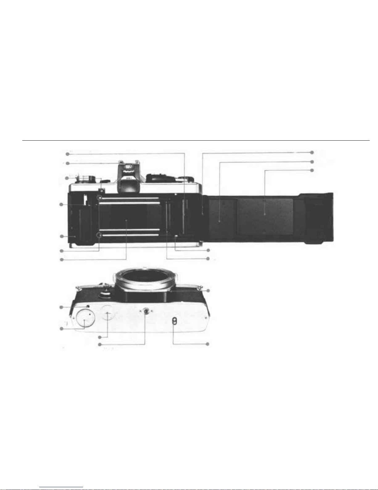
DESCRIPTION OF CONTROLS
(P. 27)
(P. 9)
Rewind Shaft
Film Chamber
Film Guide
Pins (2 )
Shutter Curtain
Motor
Guide Pin Hole
Battery
Chamber
Motor Drive Socket Cap
Tripod Socket
Camera Back
Camera Back
Pressure Plate
(P. 37)
Motor Coupling Terminal
Refer
to
pages
in
parentheses
for
detailed
explanations
of
each part.
Film Take-Up
Spool
Viewfinder
Eyepiece Frame
Battery
Check Lamp
Recordata Back Contact
Dual Sprocket
B LOCK Button
(P. 12)
(P. 9, P 44)
(P.58)
(P.8)
(P. 43)
(P. 37, P. 40)
(P. 7)
(P.37, P40)
Release Pin
2
Page 4
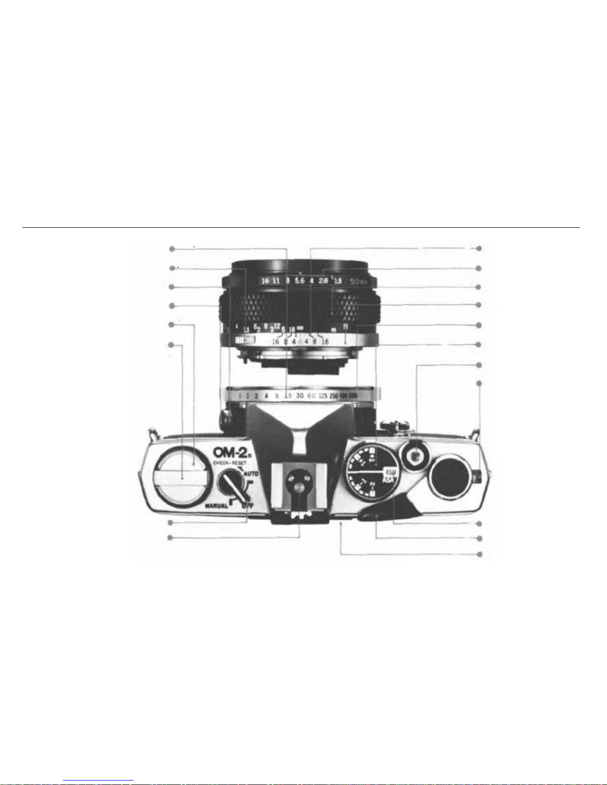
Manual Shutter
Speed Ri ng
Lens Release Button
FP and X Flash Synch Selector
Flash Sy nc hr oni za ti on Socket
Rewind Knob
/Camera Back Release
Rewind Crank
Sel ector Lever
Hot Shoe Socket
Depth of Fie ld Scale
Aperture Ring
Focusing Ring
Lens Mount Ring
Body Mount Ring
Exposure Copensation
Dial/Film Speed Dial
Shutter Release Button
/Cable Release Socket
Exposure Counter
(P. 10, P. 20)
(P. 11)
(P. 10)
(P. 11)
AS A Film Speed
Window
Film Advance Lever
Memo Holder
(P. 12)
(P. 7)
(P.30, P.35)
(P.35)
(P.20)
(P.26)
(P. 12,
P.15, P.16,
P. 17. P. 18, P. 35)
(P. 14)
(P.26)
(P. 11.
P.23)
(P.19, P.20, P.37,
P.42, P.44)
(P. 8,
P.15,
P. 24,
P44)
(P.9, P.20,
P. 44)
3
Page 5
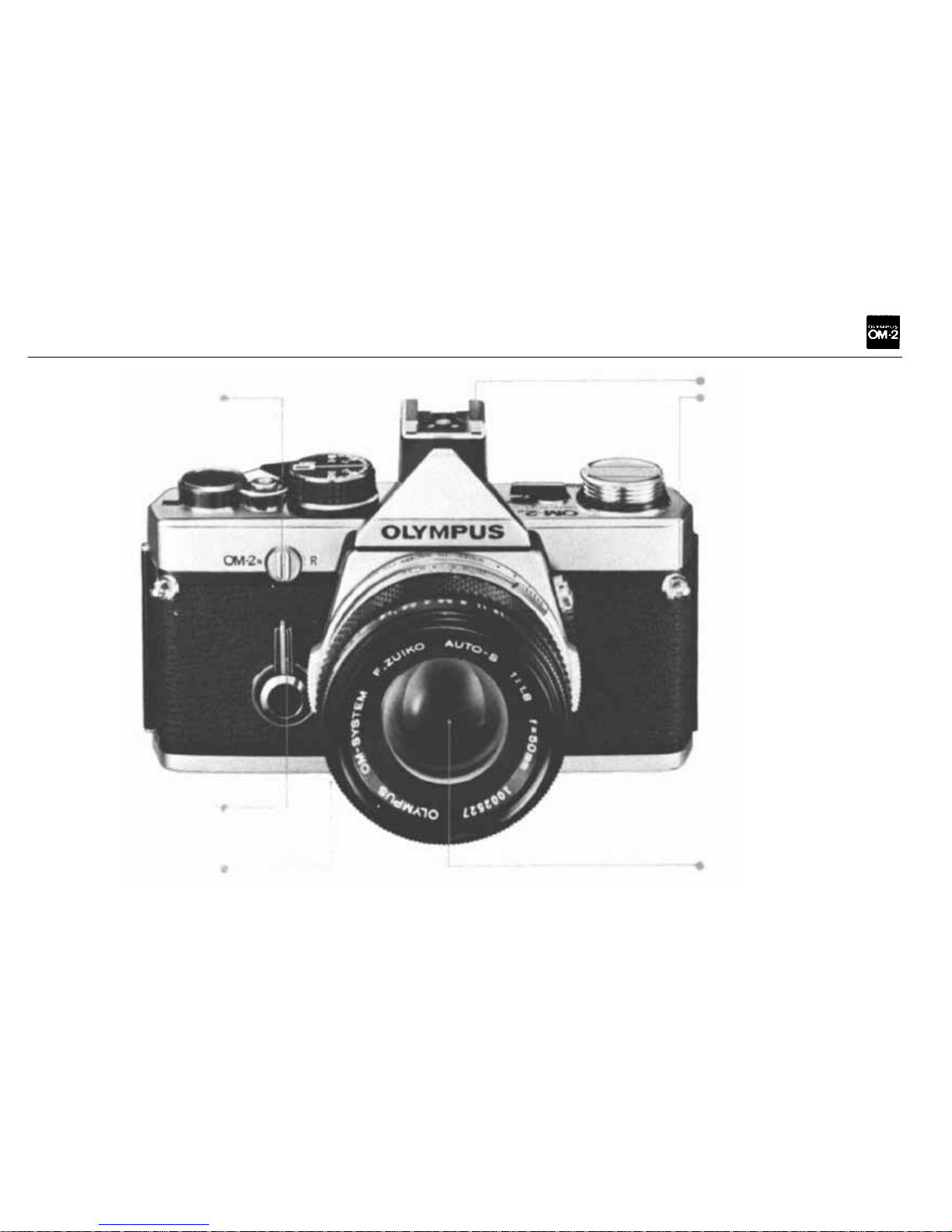
Rewind Release Lever
Accessory Shoe 4
Shoulder Strap Eyelet
Self-Timer
Depth-of-Field
Preview Button
Lens
(P.20, P.44)
(P.21, P.44)
(P. 25, P.
26.)
4
Page 6

TABLE OF CONTENTS
On
OM-2
To an
OM-2
Owner
...............
1
Description
of
Controls
............
2
Mounting the Lens/Inserting the Batteries . 7
Battery Check and Mirror Lock-Up ..... 8
Loading
the
Film
................
9
Operating the Film Advance Lever/
Exposure
Counter
..............
10
Setting
the ASA
Film
Speed
Dial
.......
11
Ap ert ur e Ring and Manual Shutter Speed
Ring
.......................
12
Setting the Selector Lever/Viewfinder .... 13,
Focusing
.....................
14
Automatic
Exposure
Control
.........
15
Manual
Exposure
Control
...........
17
Holding
the
Camera
..............
19
Unloading the Camera/Making Multiple
Exposures
...................
20
Setting
the
Self-Timer
.............
21
Exposure
Compensation
............
22
Exposure Compensation for Aut omatic
Measurement
.................
23
Exposure Compensation f or Manual
Measurement
.................
24
Depth
of
Field
.................
25
Depth of Field Scale/Preview Button .... 26
Infrared Photography/Camera Back
Replacement
.................
27
Interchangeable
Focusing
Screens
......
28
Flash Photography wi th t he T32 (T20)
Electronic
Flash
...............
29
5
Page 7

On O M System
The T32, (T20)/OM-2 Way — Flash
Photography Couldn't Be Simpler and
More
Accurate
................
32
Bounce
Flash
..................
33
Cloce-up
Flash
.................
34
Flash Photography with an Electronic
Flash
Unit
...................
35
Flash
Bulb
Photography
............
36
Motor
Drive
Photography
...........
37
Winder 2 Operation
..............
40
Care
and
Storage
................
42
Questions
and
Answers
............
44
The Most Important Feature of the
OM-2 — TT L Direct (off-the-film) Light
Measuring
...................
47
Zuiko Interchangeable Lens Group . . . . .
Table
of
Interchangeable
Lenses
......
Interchangeable
Lens
Group
Units
......
Finder
Group
..................
Finder
Group
Units
..............
Flashphoto
Group
...............
Flashphoto
Group
Units
............
Motor
Drive Group
..................
Motor
Drive
Group
Units
...........
Macrophotography
Group
...........
Macrophotography
Group
Units
.......
Phototechnical
Group
.............
Phototechnical
Group
Units
.........
Photomicrography
Group
...........
Photomicrography
Group
Units
.......
Chart
of
Photographic
Ranges
........
Case
Group
and
Units
.............
51
53
55
57
58
61
64
71
74
76
78
84
88
89
92
94
95
6
Page 8
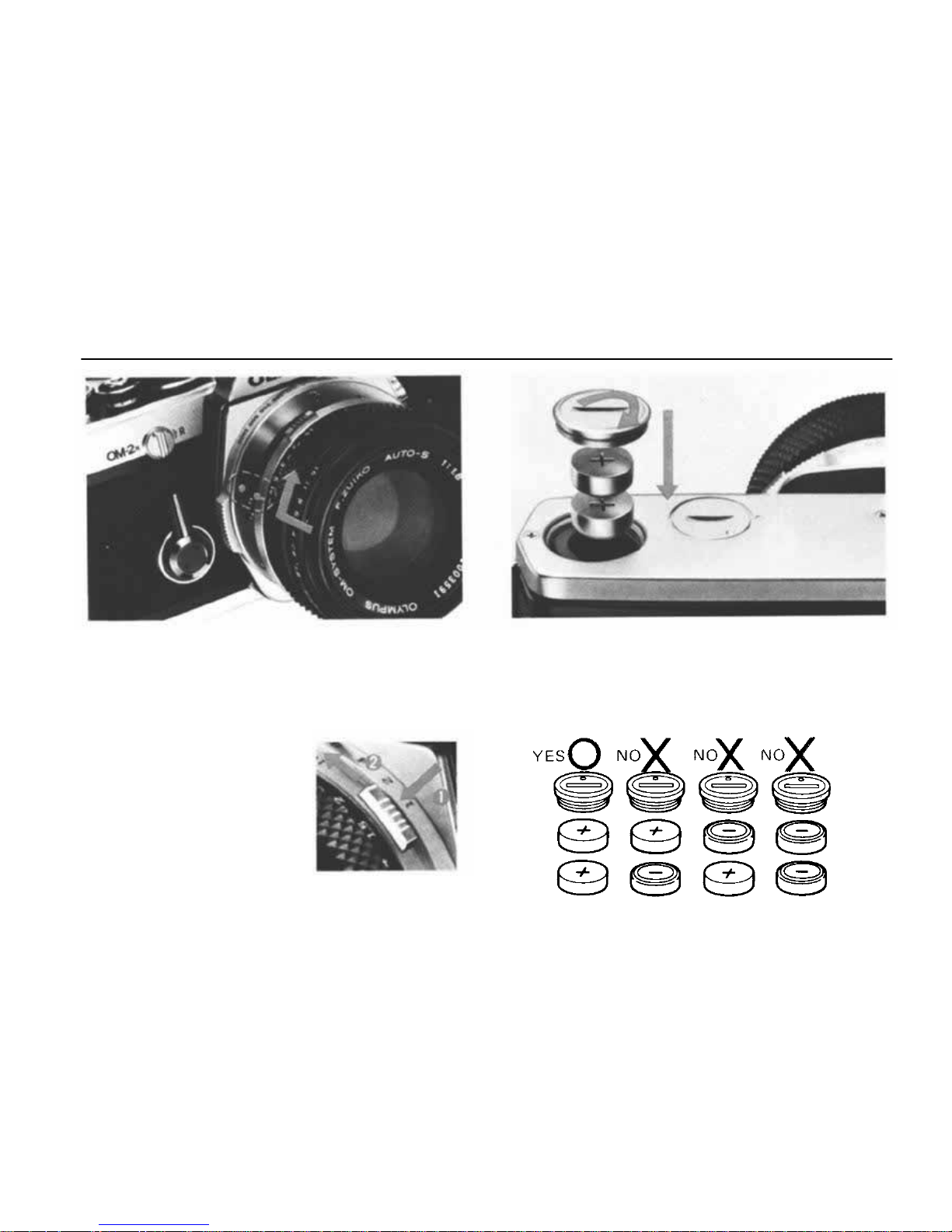
MOUNTING THE LENS
INSERTING THE BATTERIES
Moun t the Lens.
Align the red dots on the lens flange and the body
mount ring. T urn the le ns cl ockwise until the lens
release
button
springs
up and you will
hear
posi-
tive "click".
Lens Removal
To detach the lens, press
down on the lens release
button and turn the lens
counter-clockwise. Always
attach the front and rear
lens caps when the lens is
removed from the body to
prevent any possibility of
damage.
Insert two 1.5V silver oxide batteries SR44
(Eveready EPX-76 or equivalents) into the bat-
tery chamber.
CAUTION: Batteries should be always replaced
as a pair. If battery polarity is incorrect, the cam-
era does not function.
7
Page 9
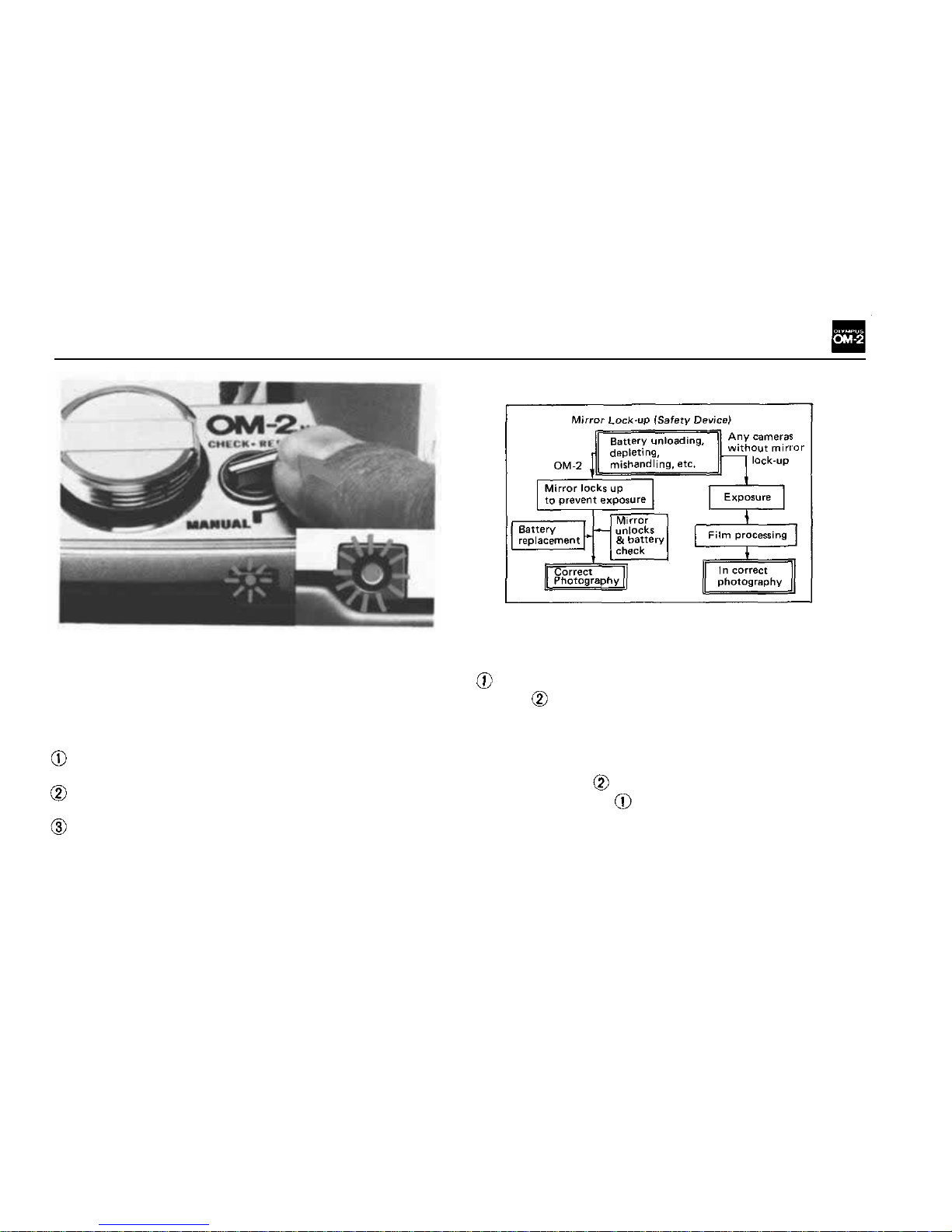
BATTERY CHECK AND MIRROR LOCK-UP
a point to switch off the selector lever when the
camera is not used.
By pressing the selector lever to the "CHECK•
RESET" position, you can check the batteries
and/or unlock the mirror.
Check the Batteries.
Move the selector lever to the "CHECK•RESET"
position. The battery check lamp indicates bat-
tery condition as follows:
The red lamp lights brightly — Battery volt-
ag e is sufficient.
The red lamp flashes on and off — Batteries
are very weak. Fresh batteries are recommended.
The lamp does not light — Batteries are drain-
ed. Replace them.
NOTE: Silver oxide batteries will last approxi-
mately one year. To avoid battery drain, make it
Mirror Lock-Up
If the mirror is up, the field of view turns dark
through the viewfinder, and the film cannot be
advanced. This lock-up of the mirror occurs when
no batteries are loaded or batteries are deplet-
ed, or the film is advanced during exposure.
The mirror lock-up does not indicate any break-
down
of the
camera,
but a
built-in
safety
device
to prevent any trouble. Press the selector lever to
the "CHECK•RESET" position, and unlock the
mirror.
In
case
,
shooting
can be
resumed
im-
mediately. In case , replace batteries.
CAUTION: You cannot unlock the mirror after
battery replacement, if you omit pressing the
selector lever to the "CHECK•RESET" position.
NOTE: When the mirror locks up, a battery drain
prevention device is activated to conserve power.
8
Page 10

LOADING THE FILM
Pull the rewind knob up
and open the camera back.
Insert a film cartridge into
the f il m chamber and push
the rewin d knob back.
Insert th e f il m leader int o
one of the slots in the film
take-up spool.
Turn the advance lever so that the film perforations engage th e sprocket teeth.
Close the camera back until it clicks.
Make sure the selector lever is in the OFF position.
NOTE: Fold out the rewind crank and rotate it
clockwise
slightly
to
remove
any
slack
in the
film.
Then if the rewind crank rotates as yo u turn the
advance
lever,
the
film
is
properly
advancing.
9
Page 11
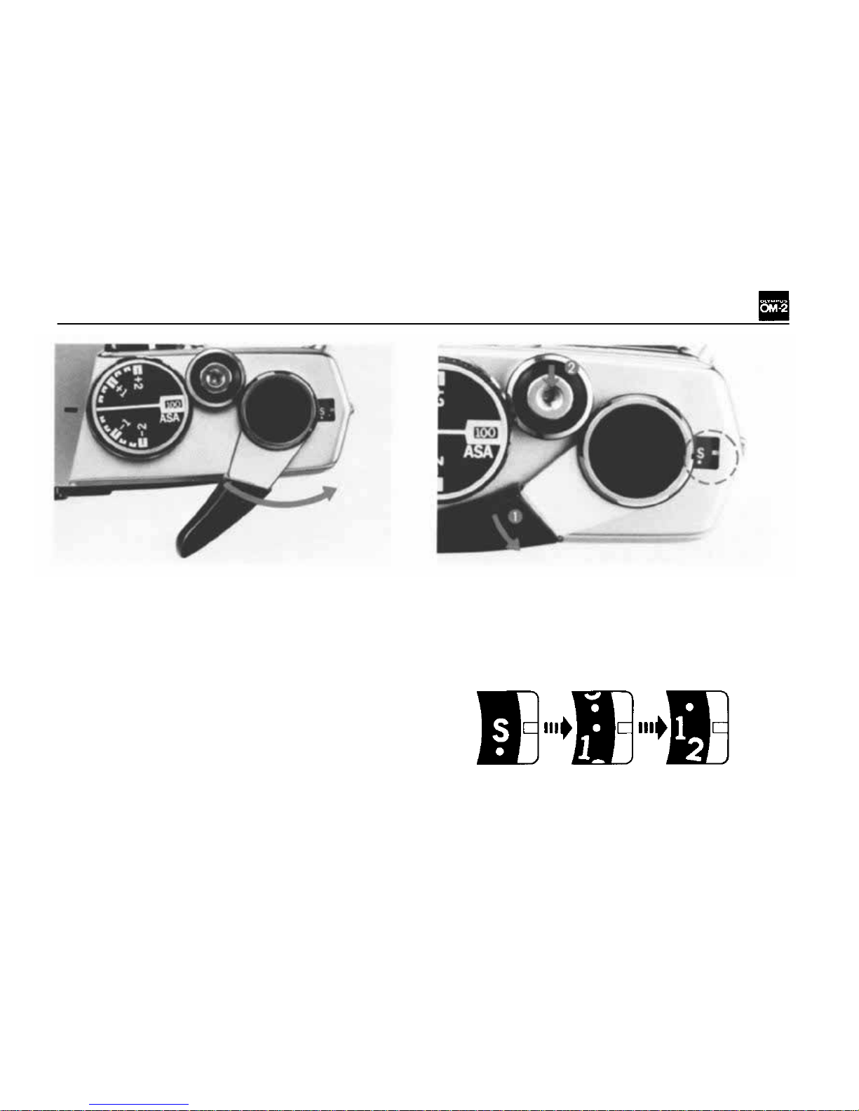
OPERATING THE FILM ADVANCE
LEVER
EXPOSURE COUNTER
Turn the advance lever to the right as far as it will
go. The fil m can be advanced by one frame, in a
single stroke or in multiple short strokes.
NOTE: If the advance lever stops moving because
you've shot the last remaining film frame while
you are
advancing
the
film,
discontinue
the
film
advance
and
rewind
the
film.
(Read
pages
37~41
fo r motor drive shooting.)
Exposure Counter
The exposure counter is indexed f rom "S" (Start)
to 1, 2 ... up to 36 in even numbers and "E"
(End). Whenever the camera back is opened, the
exposure counter automatically returns to "S".
10
Page 12

SETTING THE ASA FILM SPEED DIAL
Lift up the outer collar of the exposure compensation dial and rotate until the ASA speed
for the film appears in the window.
The ASA
film
speed
scale
on the
dial
is
mark-
ed from 12 to 1600. If you are not able to
rotate the outer collar to the desired ASA in
one turn of the d i al (only 3 stops can b e rotated
in one turn of the dial), release the collar and
turn the exposure compensation dial several
click stops in th e opposite direction from the
ASA you are trying to set. Then, lift the outer
collar again and continue turni ng to the desir-
ed ASA setting. NEVER FORCE THE DIAL
WHEN SETTING A SA.
Once the setting has been made, turn the dial
until t he white line is aligned with the black
index line on the pentaprism housing.
CAUTION: Make sure yo u align the white line
with the black index line on the pentaprism
afte r setting ASA.
THE MEMO
HOLDER
A memo holder pro-
vided on the cam-
era back accepts a
memo slip or the
end flap from most
35mm film packages
as a reminder of
ASA, exposure numbe r, etc.
11
Page 13
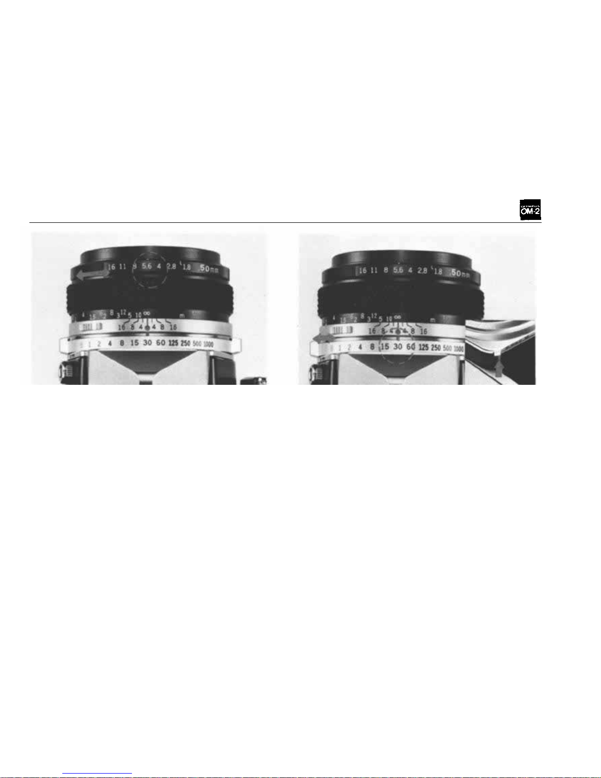
APERTURE RING AND MANUAL SHUTTER SPEED RING
Aperture Ring
The opening (aperture) in the lens diaphragm is
marked in F stops on the aperture ring. The higher
the F number, the smaller the lens opening (less
light) and provides greater depth of field than
lower F numbers (see page 25).
When setting the aperture ring, you may use either
the click-stop positions or a n y in-between settings
to obtain precise exposure control.
NOTE: All lenses in the OM System (except cer-
tain specialized lenses) provide fully automatic
diaphragm control allowing you to focus and
compose your picture with the lens fully open.
The diaphragm will automatically close to the
pre-selected F stop at the moment of exposure.
And immediately re-open after exposure.
Manual Shutter Speed Rin g
Shutter speeds engraved on the manual shutter
speed ring ar e used only for non-automatic camera
operation. B indicates
"bulb"
at
which
set-
ting the shutter will remain open as long as the
shutter release button is held down. The other
engravings indicate fractions of a second; for e x-
ample "T" for 1 second, "2" for 1/2 second .....
up to
"1000"
for 1
/1000
second.
To set at
"B",
rotate the ring while pressing the B LOCK button at the lower l eft of the body mount.
Be careful that shutter speeds are set only at
click stop positions. Make sure that the selector
lever is set at a click stop position.
12
Page 14
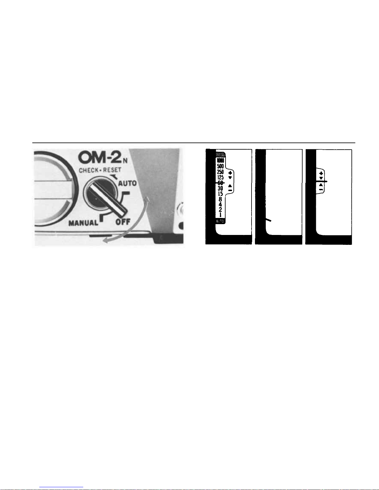
SETTING THE SELECTOR LEVER
The selector lever on top of your camera has four
positions as follows (with click stops at
AUTO-OFF-MANUAL):
1) AUTO — Automatic exposure control; you
preset the F s top and the camera automatical-
ly sets shutter speed for proper exposure.
2) OFF — Camera turned completely off to avoid
battery drain. Always store your camera with
the selector lever in this position.
3) MANUAL — Zero-method exposure operation;
set shutter speed and F stop for proper ex-
posure (see page 17).
4) CHECK•RESET
—
Battery test position simul-
taneously with release of mirror lock-up.
The three-position viewfinder control center
allows you to see the operating mode of your
camera without checking the position of the
selector lever.
NOTE:
If you
release
the
shutter
with
the
selector
lever at OFF in normal lighting condition, the
built-in automatic exposure control is activated
to take a properly-exposed picture, so as not to
miss optimum exposure opportunity, at any mo-
ment. The difference between the automatic ex-
posures in the O F F position and the AUTO posi-
tion, however, is that the OFF mode exposure
stops in 1/30 sec. maximum to save battery exhaustion, and the AUTO viewfinder scale does
not appear.
VIEWFINDER
AUTO
OFF
MANUAL
13
Page 15
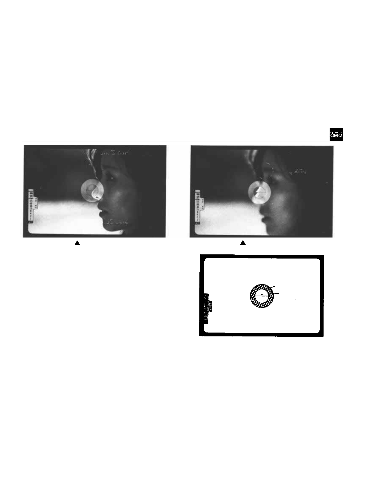
FOCUSING
Loo k throug h t he viewfinder and turn the focusing
ring
in
either
direction until
your
subject
appears
sharpest. The split image will be vertically align ed
in the central spot of the Focusing Screen or a
shimmering effect of the microprism ring around
the central sp ot wil l disappear when critical focus-
ing has been achieved.
NOTE: Y o u ca n determine the distance between
the subject and the film plane by reading the dis-
tance
scale
on the
focusing
ring
after
setting
criti-
cal focusing. The actual distance is indicated o pposite the red central index mark on the lens
mount
ring;
the
white
scale
indicates
this
distance
in meters and the orange scale in feet.
(For Focusing Screen replacement read pages 28 ,
59 and
60).
Out of focus.
Microprism
Ring
Rangefinder
Spot
Matte Field
In focus.
14
Page 16
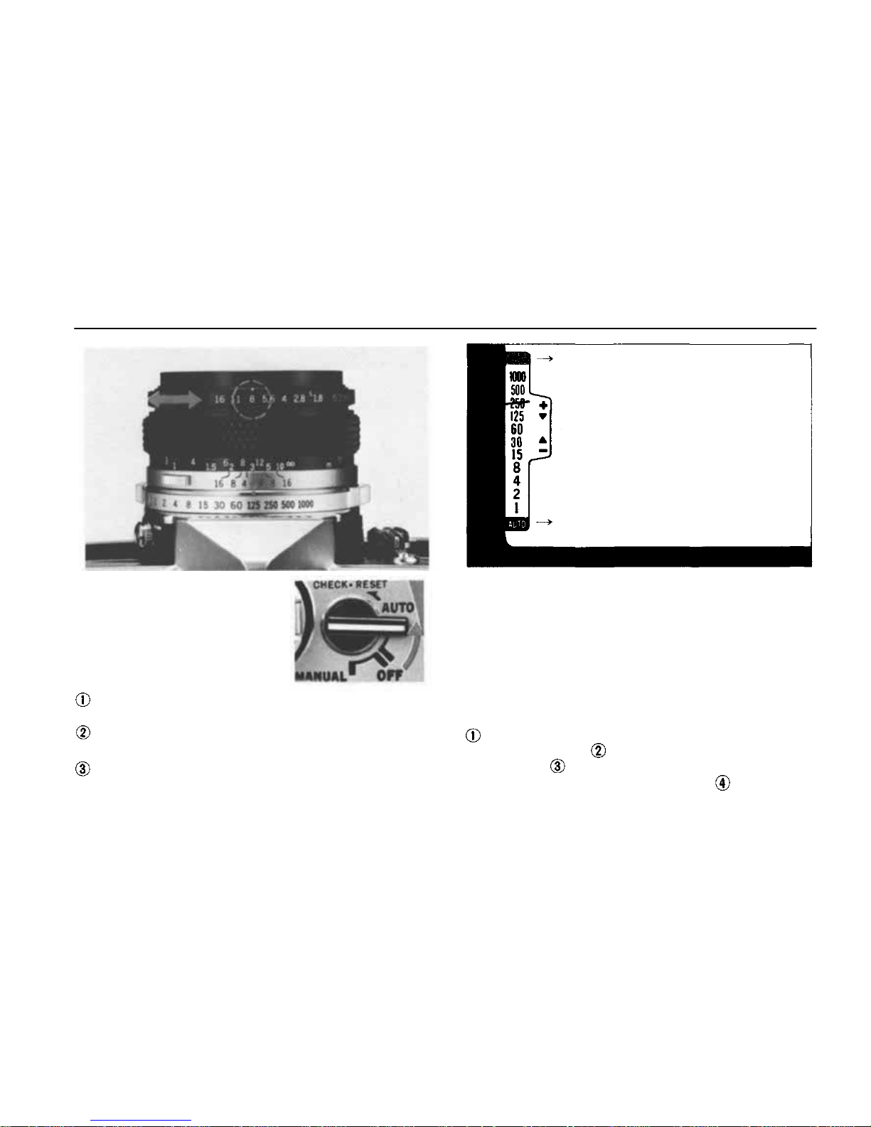
AUTOMATIC EXPOSURE CONTROL
The Aperture-Preferred System
The aperture-preferred system
is the most convenient and
easy-to-use method of auto-
matic operation, particularly
outdoors w h e n using 50mm or
wide-angle lenses. To use this system:
Set the selector lever to the "AUTO" position
making
sure
that
the
lever
"clicks"
into
place.
Set the F stop you wish to use on the lens
aperture ring.
The camera will automatically determine the
shutter speed required for proper exposure and
indicate tha t speed in the viewfinder. Then RE-
LEASE THE SHUTTER.
NOTE: At shutter speeds slower than 1 / 60 second,
the possibility of camera movement during ex-
posure is increased. If the needle in the viewf inder
indicates a shutter
speed
in
this
area,
turn
the
aperture ring to the left (so as to open the aperture).
For use of interchangeable lenses of various angles
of view, refer to the data below to determine the
hand-held shutter speed and avoid blurry pictures:
Wide-angle and super wide-angle lenses — 1/3 0
second or faster. 50mm lenses — 1 /60 second
or faster. Telephoto and Zoom lenses to
100mm — 1/125 second or faster. Telephoto
and Zoom lenses to 200mm — 1/250 second or
Red Zone
Blue Zone
15
Page 17
faster. Super telephoto lenses of 300mm and
up — 1/500 second or faster.
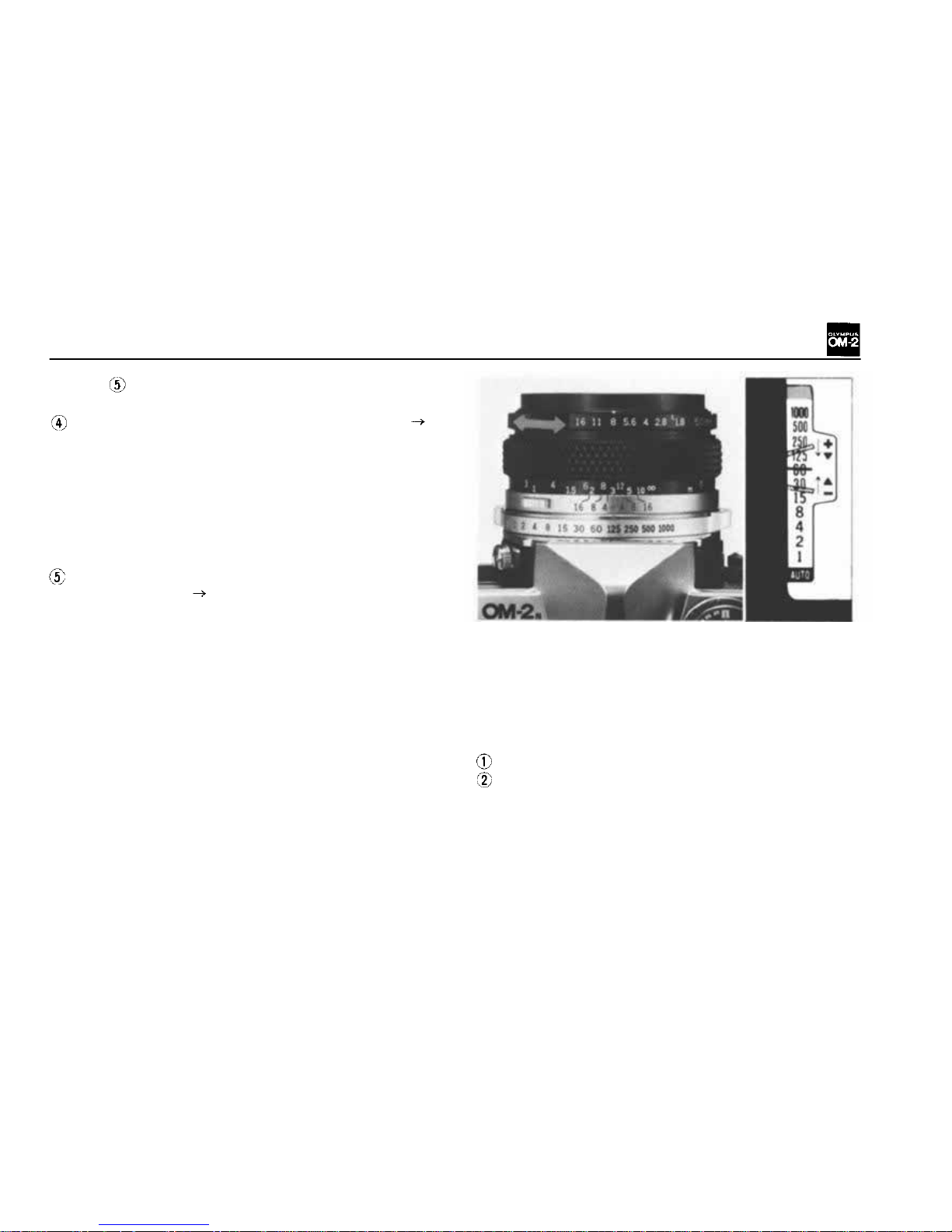
If the viewfinder needle enters the red zone
Warning against over-exposure. A shutter speed
faster than 1 /1000 second is required for pro-
per exposure, but the shutter will be released
at 1/1000 second. Since this is beyond the
range of your OM-2 and an overexposed photograph would result, turn the lens aperture ring
to a higher F stop until the meter needle moves
out of the red zone.
If the viewfinder needle enters the blue
"AUTO" zone Indication for long time exposure. A shutter speed longer than 1 second
is required for proper exposure.
Your OM-2 provides for automatic exposures
fro m 1 second to 120 seconds (with A SA 100
at normal temperature and h umidity). If you
wish to close the shutter during a long time
exposure under AUTO operation, turn the
selector lever to the OFF position, and the
shutter closes.
CAUTION: Do not advance the film while
the mirror is up during an automatic exposure,
or the mirror will lock up.
The Shutter Speed-Preferred System
Should you wish to select a shutter speed to meet
a specific photographic situation (e.g., stopping
fast action, eliminating camera movement or controlling depth-of-field), you may use a shutter
speed-preferred method of automatic exposure
control. To use this system:
Set the se le c t or lever to t h e "AUTO" position.
Look through the viewfinder and turn the
aperture ring until the viewfinder needlepoints
at the desired shutter speed.
16
Page 18
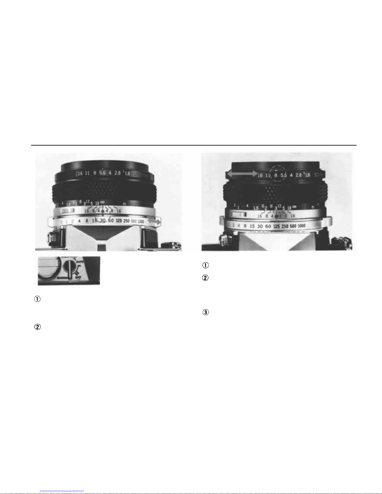
MANUAL EXPOSURE CONTROL
Set the selector lever to
"MANUAL", and the exposure index marks and
the meter needle are visi-
ble in the viewfinder.
Shutter Speed-Preferred Manual Exposure Control
Should you wish to preselect a shutter speed
turn the shutter speed ring until the desired
speed is opposite the red reference dot on the
lens barrel (see page 12).
Look through the viewfinder and turn the
aperture ring until the needle lines up in the
center of the index. For fine exposure adjustment you can use any click-stop or intermediate F stop position.
Aper t u r e- P r e f e rr e d Manual Exposure Control
Turn the aperture ring until the desired F stop
is opposite the white index mark.
Look through the viewfinder and rotate the
shutter
speed
ring
until
the
needle
lines
up as
close as possible to t he center of the index.
Make sure that the shutter speed ring is clicked
into position and not between two settings.
Make the final exposure adjustment by turning
the aperture r i n g u n t i l the needle aligns exactly
in the center of the index.
CAUTION: The shutter speed thus obtained
should meet the other photographic conditions
properly, especially at "B" where the shutter
speed ring is not coupled with t h e exposure meter.
17
Page 19
Exposure Meter Needle
Exposure Meter Index
If the Exposure Needle Does Not Center o n the
Index
If an exposure or a shutter speed is improperly
selected, th e exposure needle wi ll no t center on
the
index.
Reset
the
shutter
speed
or F
stop
until
the needle is ce n tered.
You may use an ND (neutral density) filter if the
subject is too bright, or an electronic flash or flash
bulb if the subject is too dark.
ASA 100
ASA 100
ASA 100
50mm F1.8 lens,
fully opened
50mm F1.4 lens,
fully opened
55mm F1 .2 lens,
fully opened
1/2
sec.
1/2
sec.
1/2
sec.
Light Measuring Range of the Exposure Meter
The measuring range is EV 1.5-EV17 (A SA 100,
with F1.2 55mm lens). The list above summarizes
the lowest measurable limits in dealing with extreme low light conditions.
CAUTION: If the aperture ring or shutter speed
ring is turned below the limits in the list, with ex-
tremely low lighting or the selector lever OFF,
the needle sometimes moves, but the meter is not
functioning.
18
Page 20
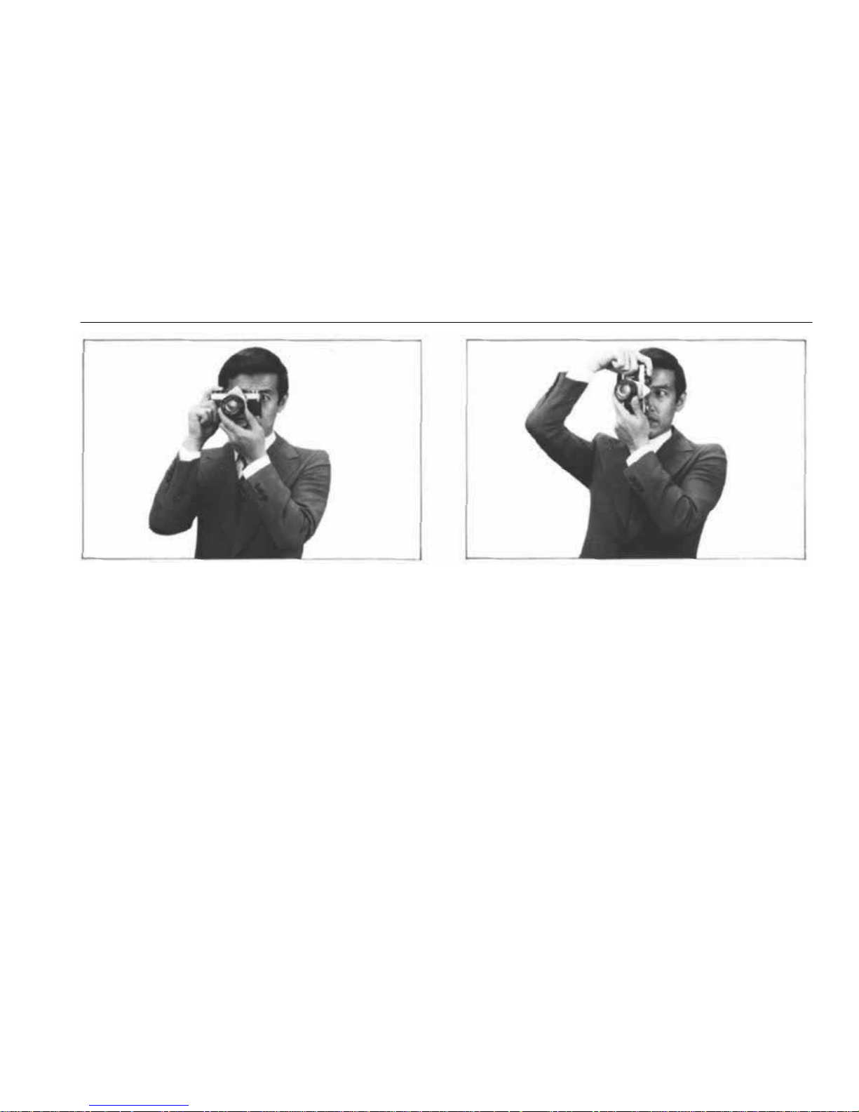
HOLDING THE CAMERA
Proper camera handling is important in assuring
the sharpest possible pictures.
Holding th e Camera Horizontally
Keep both elbows close to the body, to steady
the camera.
Putting the Camera into Operation
The aperture ring, focusing ring and shutter speed
ring ar e so arranged as to enable one hand opera-
tion right up to the moment the shutter is released.
Hold your breath at the moment of shutter release.
Transport the film advance lever with your right
thumb and squeeze the release button smoothly
using the cushion, not the tip, of your index
finger.
Holding the Camera Vertically
For vertical shooting, keep one elbow close to
your body and press the camera tightly against
your forehead.
NOTE: Steady yourself against any nearby sup-
port (such as a tree, fence, or wall) whenever pos-
sible.
NOTE: For telephotography, or slow shutter
speed photography, it is recommended that you
use a tripod and hold the camera steady with
you r hands.
19
Page 21
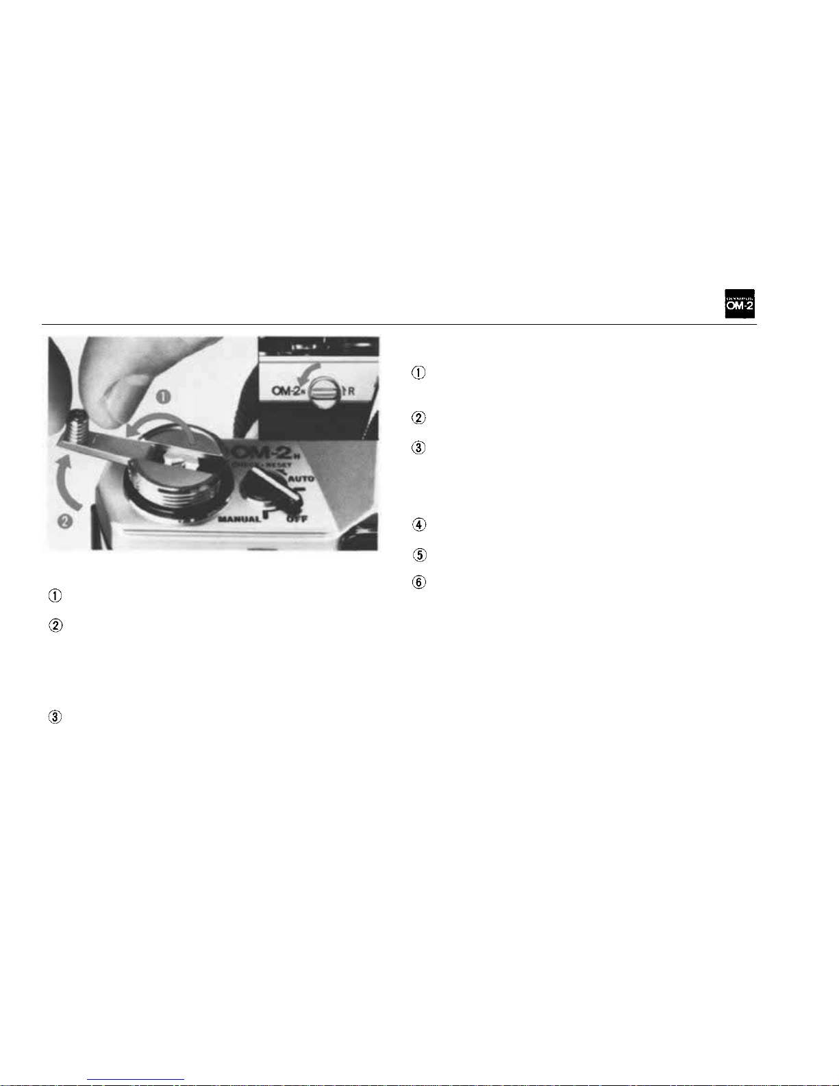
UNLOADING THE CAMERA
Whe n the entire roll of fil m has been exposed re-
wind the film.
Turn the rewind release lever counter-clock-
wise by about 90°.
Fold out the rewind crank and wind it in the
direction of the arrow. Wh ile rewinding, you
will feel tension on the crank. When the ten-
sion stops and the crank turns freely, the film
has been completely rewound back into the
cartridge.
Open the camera back by pulling up on the
rewind knob and remove the film cartridge.
Keep camera and film out of direct sunlight
while unloading.
Should you wish to make more than one exposure
on the same frame:
Take up any slack in the film by slowly turn-
ing the rewind crank in a clockwise direction
until it stops, then take the first exposure.
Turn the rewind release lever counter-clock-
wi se by about 90°.
Hold both the rewind knob and rewind re-
lease lever to prevent them from turning and
advance the film advance lever. The shutter
will then be cocked for the next exposure
without advancing the film.
Press
the
shutter
release
button
with a slow,
steady squeeze.
The exposure counter will advance with each
exposure.
After completing the multiple exposures, put
the lens cap on the lens, advance the film, and
shoot a blank fra me to avoid overlapping.
NOTE: You can make as many multiple exposure
as yo u li ke by repeating the above procedure. With
each exposure on the same frame, the possibility
of slippage is increased.
MAKING MULTIPLE EXPOSURES
20
Page 22
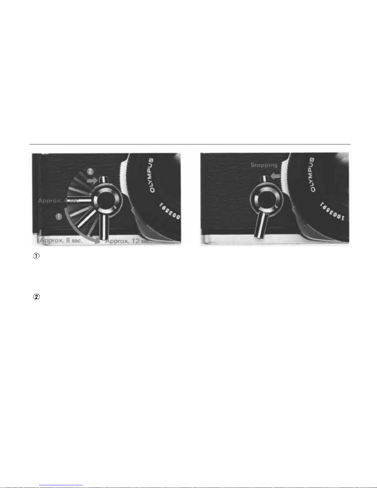
SETTING THE SELF-TIMER
Rotate the self-timer lever counter-clockwise
so that the shutter can be released after an
elapse of delay time between 4 sec. to 12 sec.
according to the lever setting as shown above.
You may set the self-timer lever either before
or after advancing the film.
Turn the start lever clockwise to the vertical
position to activate the self-timer lever. The
shutter will then be released after the preset
time.
Stopping the Self-timer
To stop the self-timer during its operation, turn
the start lever count er-clock wise. If you tu rn the
start lever clockwise again, t he self-timer can re-
sume its action.
NOTE: After setting the lever, you can release
the
shutter
by
pressing
the
shutter
release
button.
NOTE: If you do not reset the self-timer, the
timer lever will begin moving immediately after
advancing
the
film
and the
shutter
will
be
releas-
ed earlier than expected. If the film has not been
advanced fully, the timer lever will stop half-way.
To re-activate the timer, move the start lever
counter-clockwise to stop the timer lever, return
the timer lever to the starting position, and ad-
vance
the
film.
Then,
turn
the
start
lever
again.
21
Page 23
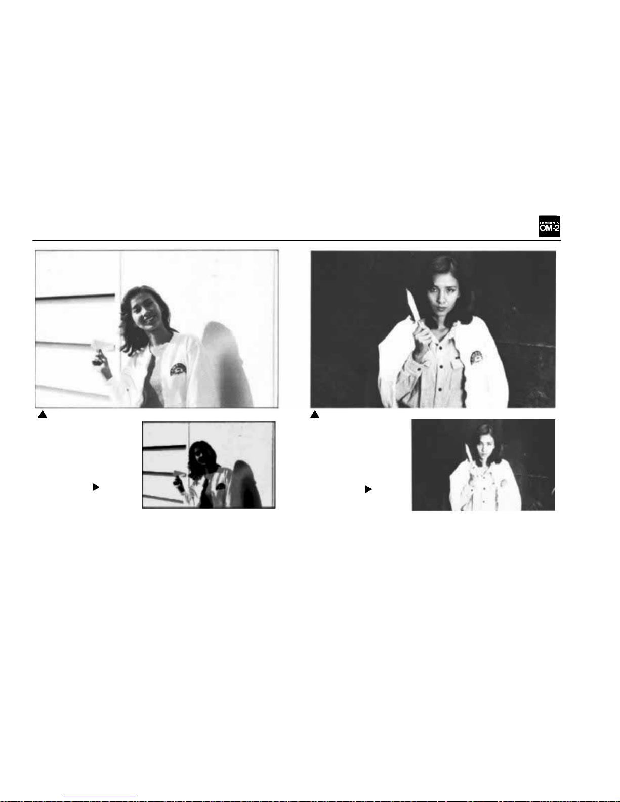
EXPOSURE COMPENSATION
Before compen-
sation
When the most im-
portant area of the picture is much darker than
the general picture area (blue sky, snowfield,
etc.), the meter will have a tendency to read the
brightest part of the picture leaving the main subject under-exposed. Alternatively, when taking a
picture of a bright subject against a dark background the meter tends to read the darkest part
Before compen-
sation
leaving the main subject over-exposed. In these
situations, proper exposure compensation helps
you take fine pictures.
NOTE: With backlighting or sidelighting it's al-
wa ys a good idea to use a lens hood to eliminate
unwanted glare.
After compensation
After compensation
22
Page 24
EXPOSURE COMPENSATION F O R AUTOMATIC MEASUREMENT
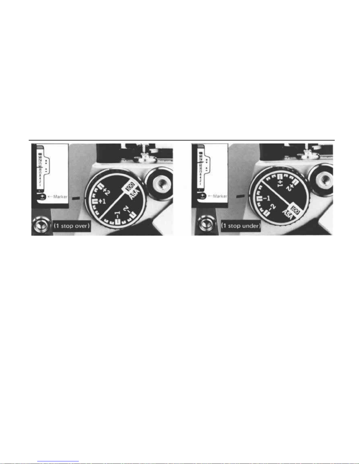
If you wish to change the exposure setting automatically selected by the camera, use the exposure
compensation dial and a compensation marker
appears in the viewfinder.
When the main subject is much darker than the
general background or when strong light strikes
the subject from behind or from the side, turn
the dial to the ( + ) side.
Turn the camera to the subject so that the subject
fills most of the viewfinder, or move the camera
toward the subject. After reading the shutter
speed, return to the original position and rotate
the compensation dial until the meter needle
points at the read-out speed in the finder.
NOTE:
In
such a case
it is
recommended
to
turn
the compensation dial to the + 1 side.
When taking a picture of a bright subject against
a dark background (spotlightng, deep shadows,
etc.), turn the compensation dial to the (—) side.
Move forward until the subject fills as much of
the viewfinder as possible, (with a zoom lens, you
may be able to do this by zooming in on th e subject without chaning your positions). After
noting the shutter speed indicated by the meter
needle, return to your original position, recompose
the picture, and turn the compensation dial until
the shutter speed needle indicates the speed obtained from your close-up meter reading.
23
Page 25
EXPOSURE COMPENSATION FOR MANUAL MEASUREMENT
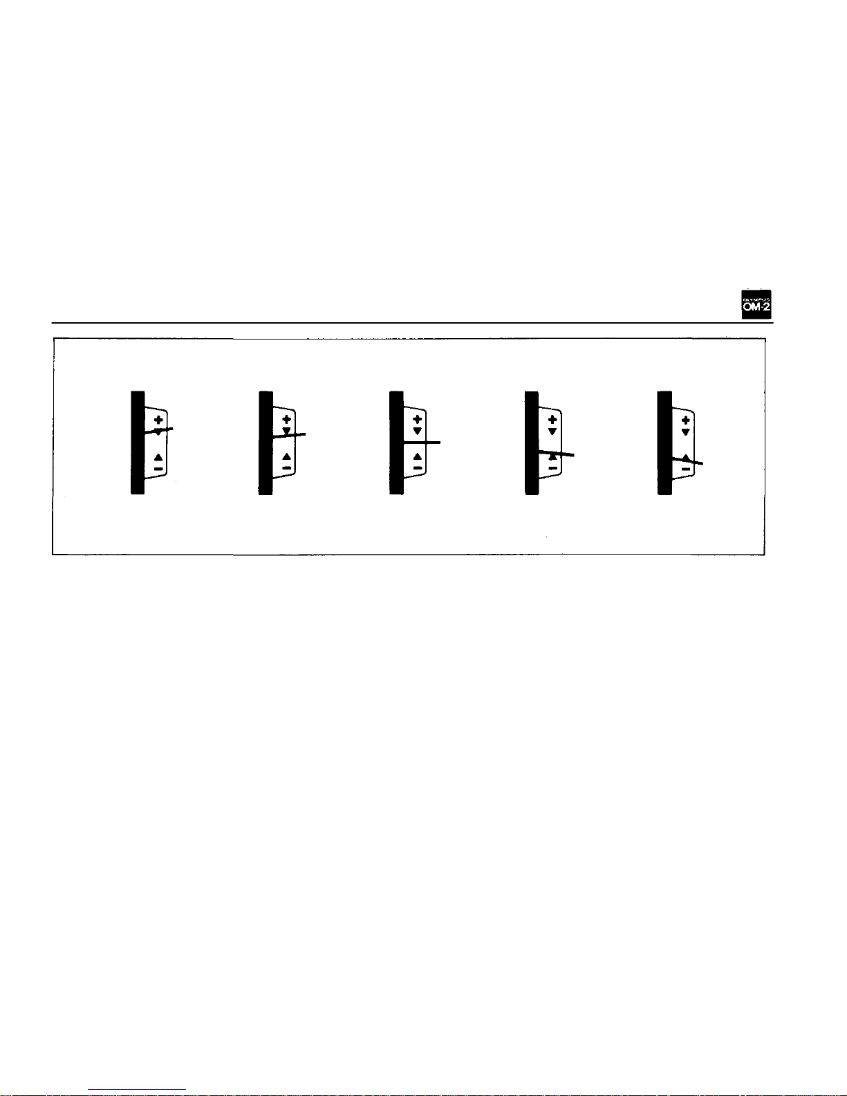
1 Stop Over
1/2 Stop Over
Correct Exposure
1/2 Stop Under
1 St op Under
Manual exposure can be compensated by adjusting the F stop or shutter speed. The exposure
needle indicates over-exposure at the (+) side, or
under-exposure at the (—) side.
Dark subject in bright backlighting
When the most important area of the picture is
much darker than the general picture area (strong
light hitting the main subject from behind or from
the side) the meter will have a tendency to read
the brightest part of the picture leaving the main
subject under-exposed. To compensate for this,
move forward until the subject fills most of the
viewfinder picture area and set the F stop/shutter
speed combination which centers the meter needle
between the index marks. Return to your original
position and take the picture without changing
this F stop/shutter speed combination even though
the needle is not centered.
NOTE: Over-exposure by + 1 stop renders a good
result in such a case.
Bright subject in d ark background
As previously mentioned, fill the viewfinder pic-
ture
area
with
the
subject
as
much
as
possible,
and set correct light measurement. Return t o your
original position and expose fo r fin e pictures.
CAUTION: After taking a picture using the com-
pensation dial, be sure to return the dial to the
normal setting
24
Page 26
DEPTH OF FIELD
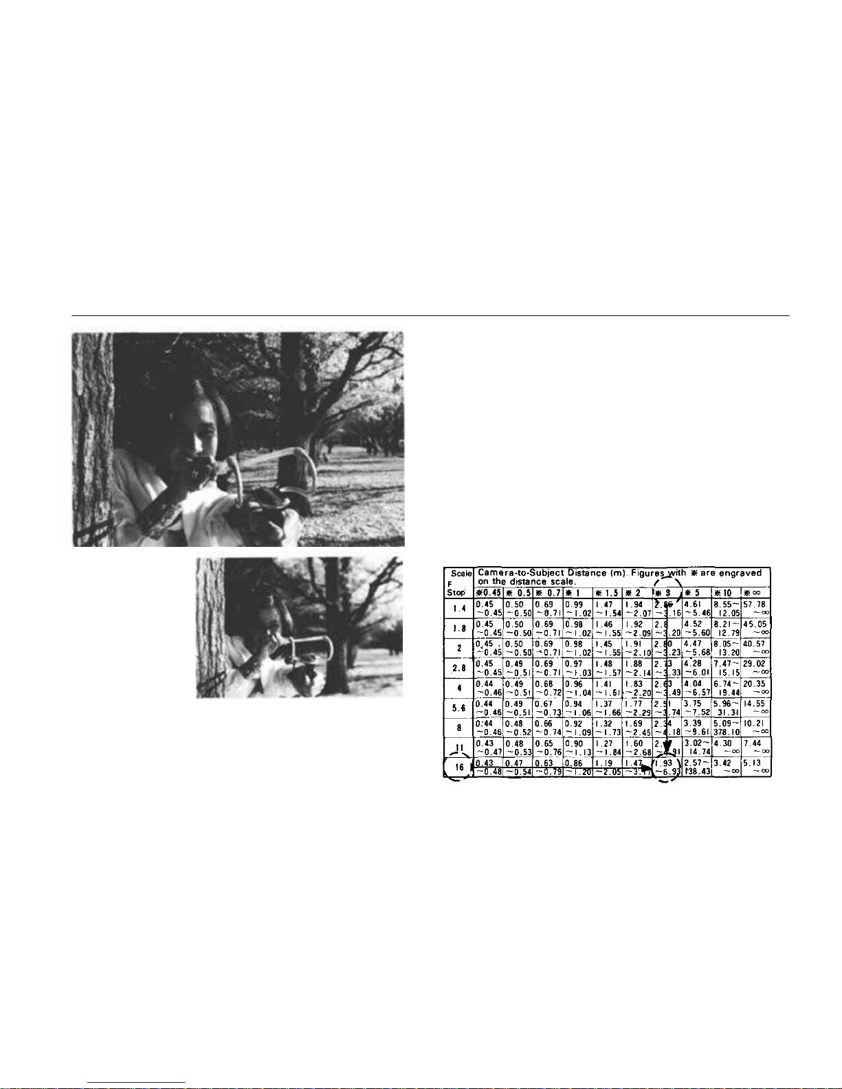
F1 6 , 1 /15 sec.
F2, 1/1000 sec.
Depth of field is the area of acceptable sharpness
in front of and behind the subject in focus. As
you get closer to your subject or as you open your
lens (e.g. from F16 to F2.8) the depth of field
becomes shallower. By stopping your lens down
(e.g. from F2.8 to F16) or getting f arther away
from your subject this depth of field can be increased.
The table below shows that when the camera-
to-subject distance is 3m, the depth of field at
F16 ranges fro m 1.93m t o 6.93m.
As you
press
the
preview
button,
looking
through
the viewfinder, you can ascertain the actual depth
of field.
Depth of Field Table (F1.8 & F1.450mm Lenses)
Circle of least confusion 1 /30mm
25
Page 27
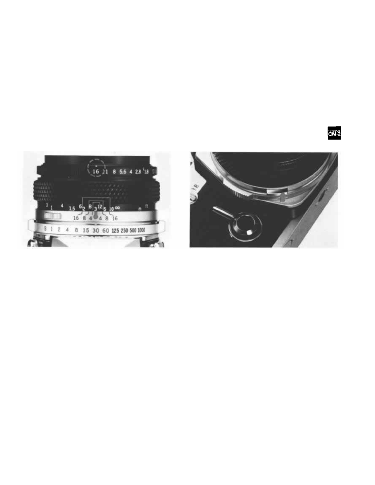
DEPTH OF FIELD SCALE
PREVIEW BUTTON
The double series of numbers engraved on the
depth of field scale represents F stops: F4, F8,
and F16. Once you have focused on your subject,
all objects within the distance range indicated
on the lens distance scale between the marks for
the F stop you have selected will have acceptable
sharpness. For example, in the above picture, th e
camera-to-subject distance is 3m (10ft.) and the
lens is set at F16. If you read the distance scale
at the points opposite the engraved "16" on both
sides of the refer enc e dot, you will find that the
depth of field is from 1.9m (6ft. ) to 7m (23ft.).
When you wish to see which objects fall within
the acceptable zone of sharpness (depth of field),
press the preview button on your lens. The diaphragm of the lens will stop down to the preset
F stop enabling y ou t o see th e depth of fi eld in
the viewfinder.
CAUTION: If you jerk the preview button while
depressing the shutter release button halfway
down the shutter might be released.
26
Page 28
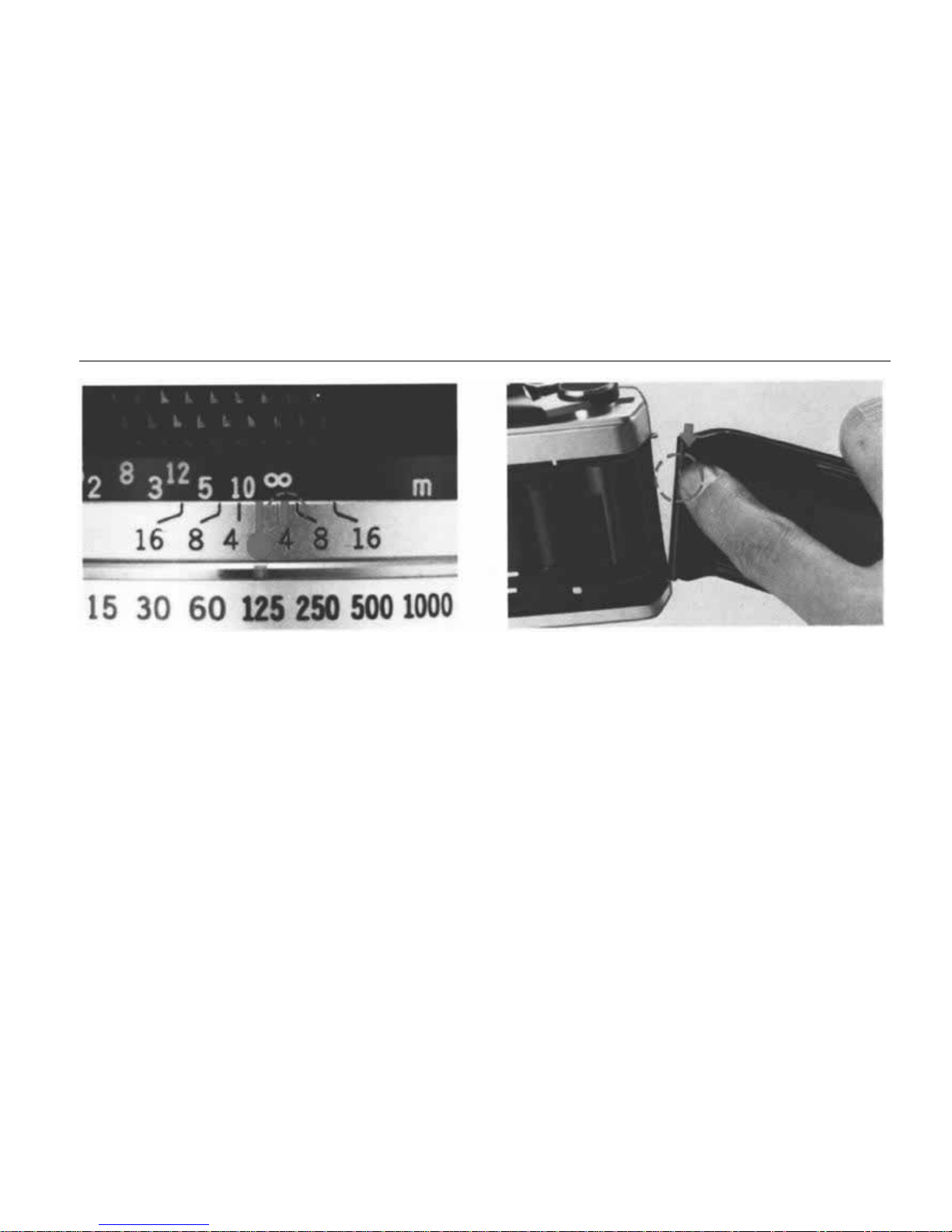
INFRARED PHOTOGRAPHY
CAMERA BACK REPLACEMENT
The OLYMPUS OM System Lenses are provided
with an infrared index mark engraved in red on
the depth of field scale.
When
shooting
with
infrared
film,
focus
normally
on your subject without the red filter on and read
the subject distance on the distance scales. Then,
turn the focusing ring to the right until the distance reading is opposite the infrared index mark.
Your
lens
will
then
be in
focus
for
average
in-
frared photography. Shoot with the red filter on.
In the above picture, the red index is set at infinity.
CAUTION: Due to special light gathering requirements of infrared films, it is recommended that
you follow the film manufacturer's recommendations regarding exposure.
The camera back of the OM-2 is fully interchanbe-
able with the Recordata Back 2, 3 and 250 Film
Back 1. To remove the camera back, push down
on the release pin as shown. Do not remove the
back unless necessary.
The Recordata Back 2, 3 registers data such as
date, number, alphabetical code, etc. directly on
the picture.
The 250 Film Back 1 is designed for winder or
motor drive shooting; it accepts a bulk loaded
magazine of 250 frames.
27
Page 29

INTERCHANGEABLE FOCUSING SCREENS
The OM System interchangeable focusing screens
provide
you
with
the
ultimate
in
focusing
versa-
tility.
Optional
screens
are
available
to
suit
virtual-
ly every picture-taking situation. The focusing
screens come with a special tool. To remove the
focusing screen:
a) Detach the camera lens from the camera body.
b) Use the special tool provided to push up on
the release catch underneath the top ledge of
the mirror box (see the photo above). This
allows the screen and screen frame to drop
down.
c) Remove th e screen from inside t h e camera by
gripping th e tip of the screen wi th the tool as
shown.
CAUTION: Although the above procedure can be
done with fingers, it is recommended that you
use the special tool supplied. Changing focusing
screens is a procedure to be exercised with great
care. Trying to change a screen with you r fingers
can result in fingerprints and costly damage to
the surface of the screen, the prism, or the mirror.
Should this occur, cleaning or repair MUST be
handled by an authorized service center. Such
damage is not covered by the product warranty.
d) To install the screen, fi t it into th e frame and
push the frame upward gently until it clicks
into place. Gently shake th e camera body to
make sure the screen is held securely in place.
28
Page 30

FLASH PHOTOGRAPHY WITH THE T32(or T20) ELECTRONIC FLASH
Electronic Flash T20
Electronic Flash T32
T32 calculator panel (blank side for TTL "OTF" Auto flash)
The T32 and T20 are the world's first fully automatic electronic flash units. All their functions are
controlled directly by the OM-2 to perform ex-
tremely easy, yet highly accurate flash exposures.
(See pp. 61~69 fo r further information on flash
units.)
29
Page 31
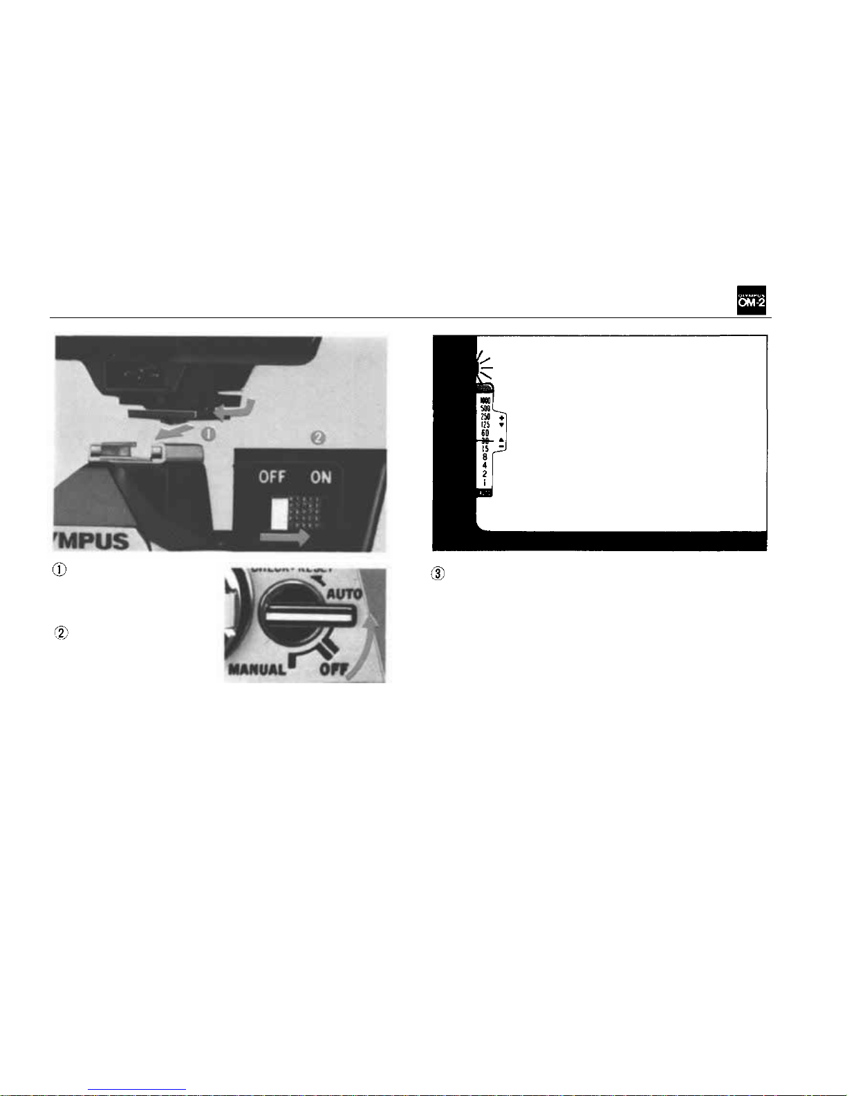
Attach the Accessory Shoe 4 to the
OM-2 and mount the
T32 (or
T20).
Set the camera's se-
lector lever to the
"AUTO" position
and switch on the
T32 (or
T20).
NOTE: Mounting the T32 (or T20) on the accessory shoe automatically completes the "X" synchro circuit. It is not necessary to set the X and
FP flash selector to "X".
A red lamp lights in the viewfinder when the
T32 (or T20) capacitor is charged ready for
shooting.
Set the aperture ring to the f/stop you require,
focus on t he subject and release the shutter.
NOTE: All f/stops on the camera lens can be
used.
30
Page 32
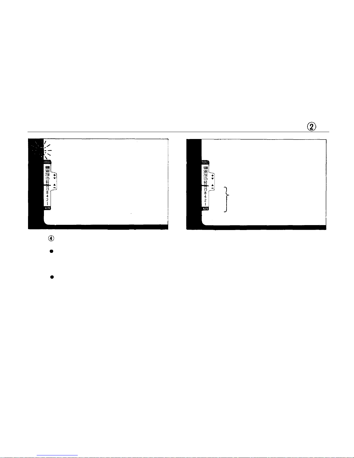
FLASH PHOTOGRAPHY WITH THE T32 (or T20) ELECTRONIC FLASH
Light Bl ue
If the lamp flickers: correct flash exposure
has been made.
If the lamp goes out: flash-to-subject dis-
tance is beyond the TTL AUTO working
range. Open up the lens stop or move in
closer to the subject.
If th e lamp stays lighted: correct exposure
has b een made by existing light, requiring
no flash.
In case exposure must be achieved by flash illumi-
nation, turn the aperture ring until the meter
needle points to 1/30 sec. or slower, and shoot.
NOTE: The OM-2 incorporates an incorrect flash
prevention system. If the shutter speed is faster
than the flash synchronizing range, the electronic
flash will not fire when you press the shutt er re-
lease
button.
31
Page 33
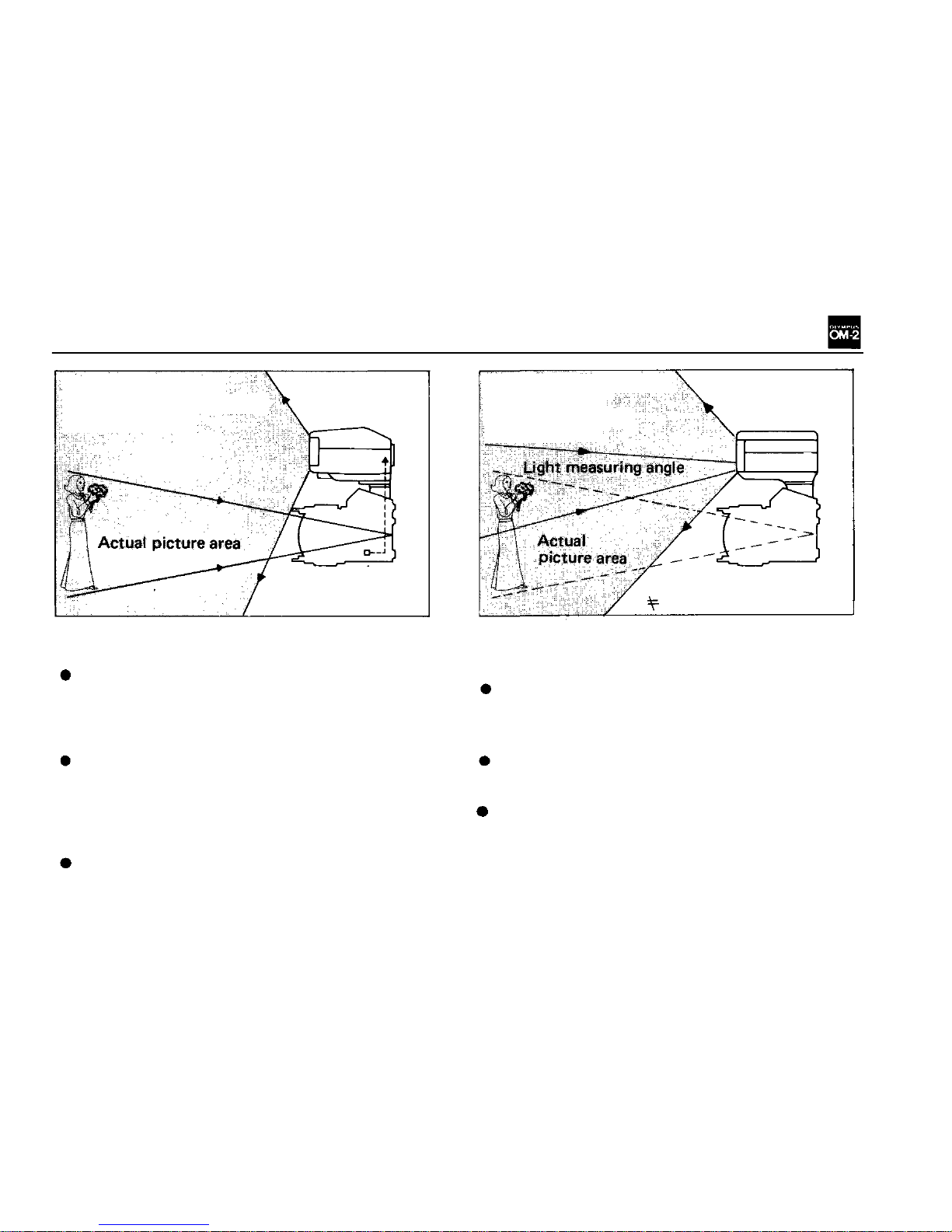
THE T32(T20)/OM-2 WAY—FLASH PHOTOGRAPHY
COULDN'T BE SIMPLER AND MORE ACCURATE
T32
(T20)
and
OM-2
(TTL Centralized Control
fla sh operation)
Picture angle
= Light measuring
angle
All required of the T32 (T20) is a flick of the on /
off switch. The rest is taken care by the OM-2.
The dial settings required of conventional
"auto" flash units — ASA film speed setting,
aperture setting, flash mode switching, exposure
compensation — are not needed with the T32
(T20).
Unlike conventional auto flash units which regula te fl a s h e mis si on by an independent light sensor, the T32 (T20) utilizes the OM-2's own built-
in SBC light sensors, so that flash acceptance angle
always coincides with the picture angle of the
camera lens.
The OM-2 shutter automatically closes at the
instant the flash exposure has been completed.
Ordinary electronic flash
unit and camera
(Normal automatic
fla sh operation)
Picture angle
Light measuring angle
eliminating camera shake. Correct exposure can
be confirmed without taking your eye off the
viewfinder.
By the incorporation of an incorrect flash prevention system, the electronic flash will not fire
if the shutter speed is faster than the synchronizing range.
Special techniques such as diffused lighting
are made easy, obviating complicated compensa-
tions and guesswork.
Usable f l ash-to-subject distance range is greatly
expanded - from 18cm (F22) to 26m (F1.2)
with a guide number of 32 (ASA 100, meters).
(From 0.6 ft. to 86 ft. with a guide number of
104 at ASA 100.).
32
Page 34
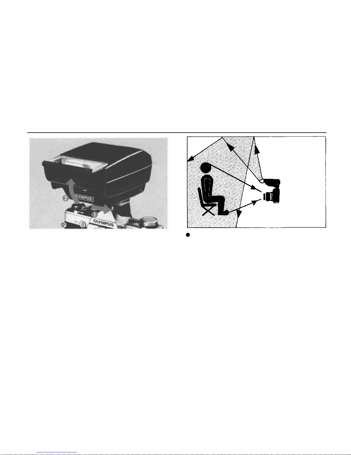
BOUNCE FLASH
Th e T32 flash surface can be tilted upward through
an angle of 90°, providing easy bounce TT L Auto
flash.
Point the flash surface at the ceiling so that
the subject is illuminated by soft reflected
light.
33
Page 35
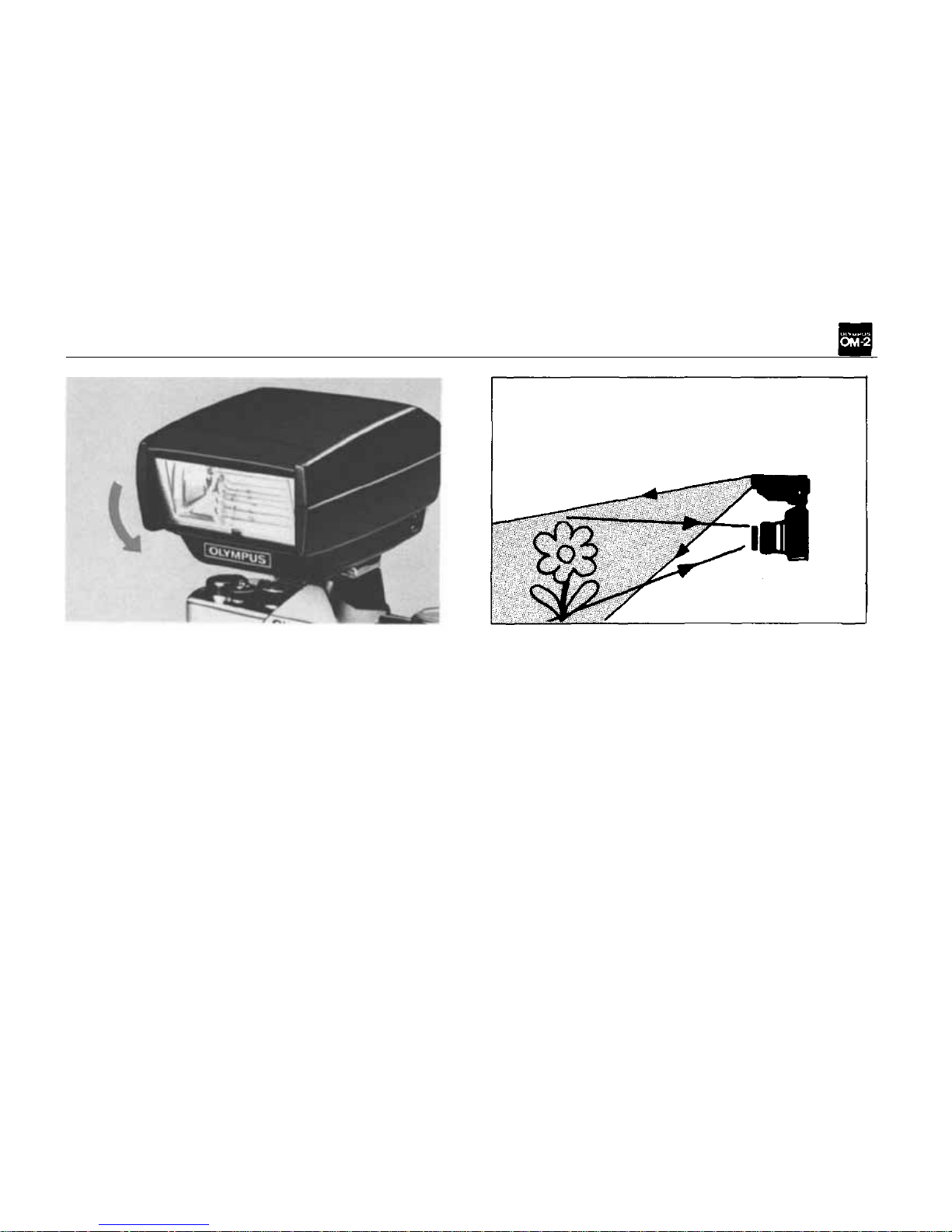
CLOSE-UP FLASH
Close-up in TTL Auto flash can be achieved simply by tilting the flash surface downward (up to
15°).
34
Page 36
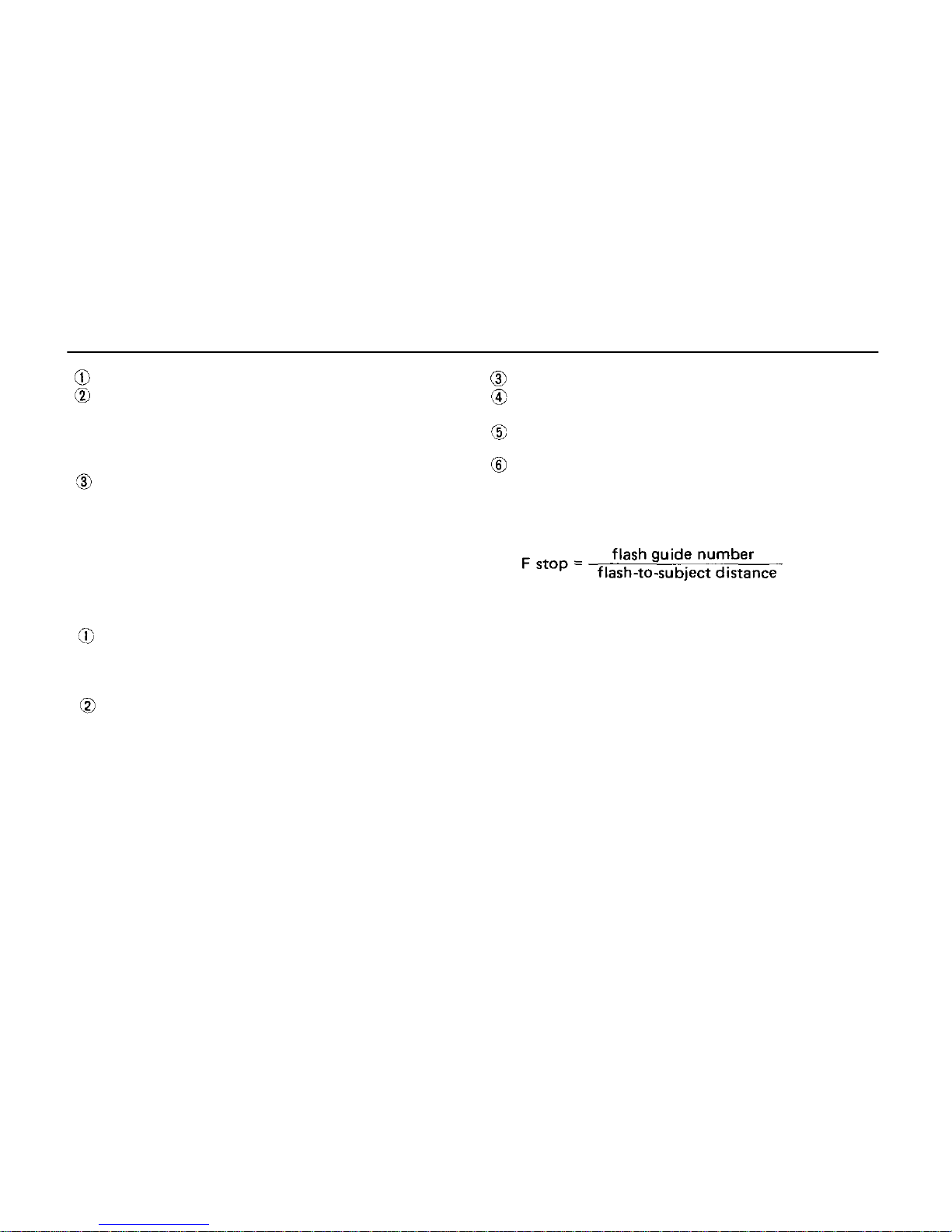
FLASH PHOTOGRAPHY WITH AN ELECTRONIC FLASH UNIT OTHER THAN THE T32-T20
Attach the Accessory Shoe 4 to the OM-2.
Mount the electronic flash on the accessory
shoe.
If your electronic flash unit does not have a
direct contact "hot shoe", connect its synchronizing cable to the camera flash socket.
Set the synchro terminal to "X" by aligning
the red dot on the FP and X selector with
the "X" indication alongside the flash socket.
Set the ASA f ilm speed on th e flash unit.
Set the shutter speed ring to 1/60 sec. or slower.
Set the flash unit to the automatic or manual
setting.
Set the desired F stop on the flash unit (in the
case of auto mode), and then set the aperture
ring to this F stop. In the case of manual mode,
F stop can be determined by using the followin g formula:
NOTE: Mounting the electronic flash unit on the
accessory shoe automatically completes the "X"
synchro circuit. However, there are some flash
units which do not fire unless the selector is set
to
"X".
[Wi th Quick Au to 310 ]
The Quick Auto 310/OM-2N (not OM-2)
combination cannot perform the TTL
("OTF") Auto flash. Use it in the Normal
Au t o or Manual flash mode.
Set the camera's selector lever to " MANUAL".
35
Page 37
FLASHBULB PHOTOGRAPHY
Plug the synchronizing cable leading fro m the
flash unit into the camera flash socket, and
then attach the fla s h unit to the camera.
Select the proper synchro setting from the
table below according to the type of bulb be-
ing used, and align the red dot on the X and
FP flash selector with the "X" or "FP" indication alongside the flash socket.
CAUTION: With the clip-on type "FP" class flash
unit,
the
synchronizing
cable
must
be
used
to
connect th e unit a nd the camera.
Select the proper shu tter speed fro m the table
below , and set the shutt er speed ri ng accord-
ingly.
Determine the correct F stop for flash exposure
by using the calculator dial, exposure chart or
guide number formula. Set the aperture ring
to this F stop.
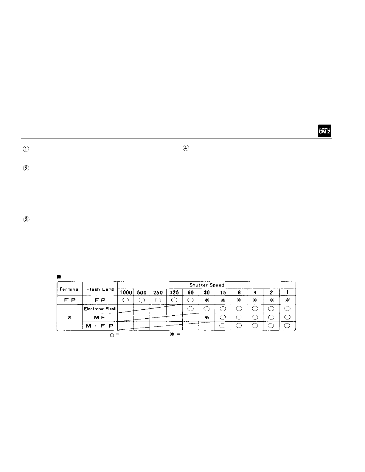
The table indicates proper synchronization speeds f or mos t flash equipment.
Recommended;
Not recommended due to bulb quality
36
Page 38
MOTOR DRIVE PHOTOGRAPHY
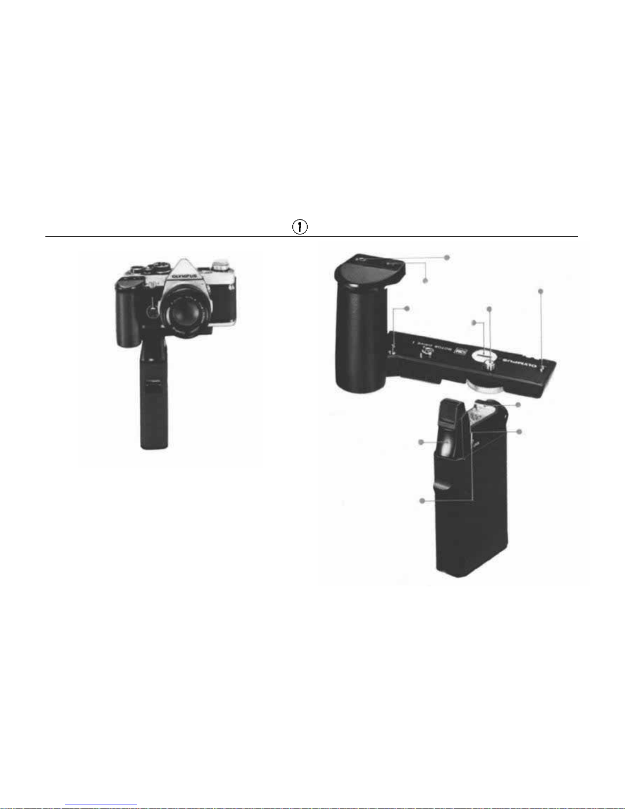
Motor Drive 1
The standard motor drive unit form s th e heart of
the Motor Drive Group. An extremely high-performance unit capable of high-speed sequence
shooting at 5 frames per second, operating off
various power units. Can be switched to the
"single" mode of operation, winding film at a
high speed of 0.16 second per frame.
Motor Drive 1
Shutter Release
Shutter Release
Lock Lever
M. 18V Control G ri p 1
Mounting
Catch
Grip Lock
Remote Control Jack
Camera Coupling
Terminal
Shutter Release
Guide Pin
Socket Cap
Storage
Clamping
Screw
37
Page 39
Attaching the Motor Drive 1
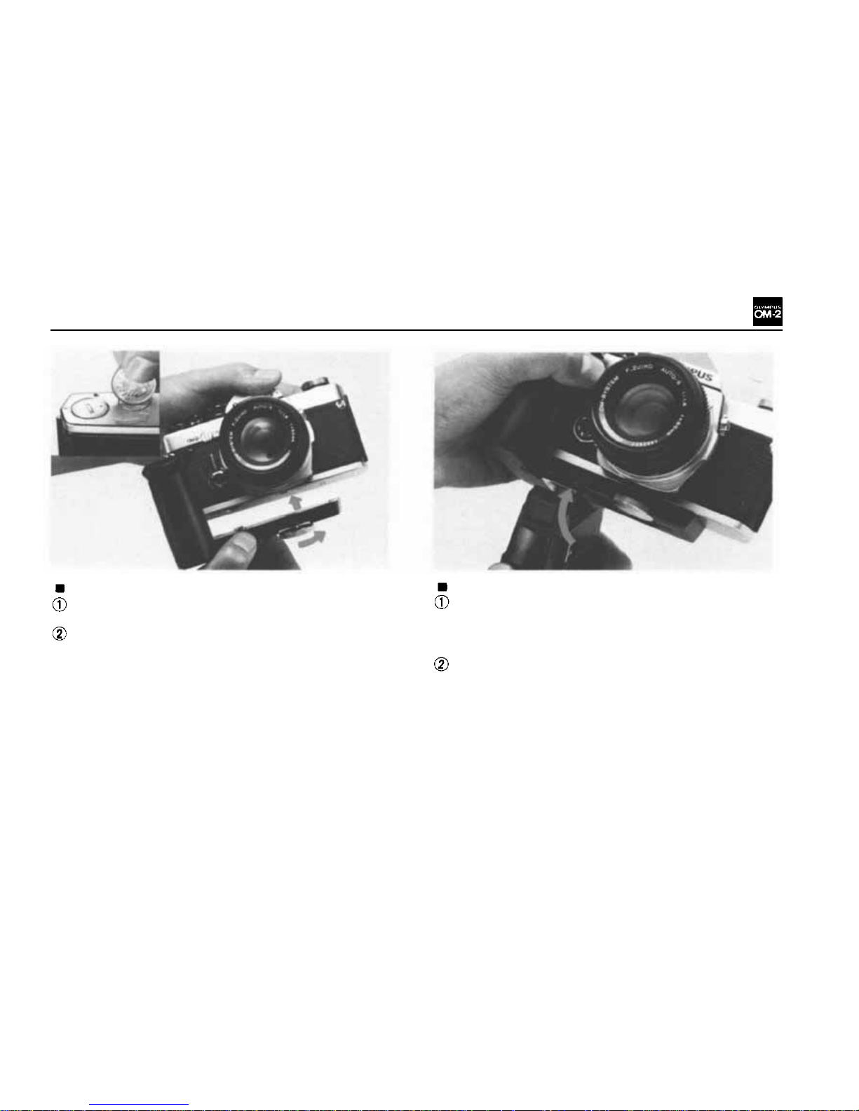
Remove the motor drive socket cap from the
camera base plate.
Insert the motor drive guide pin into t h e guide
pin hole on the camera base plate. Turn the
clamping screw clockwise until the Motor Drive
1 is securely attached to the camera base plate.
Attaching the M. 18V Control Grip 1
Remove the M.18V Battery Holder 1, insert
twelve 1.5V penlight (A A ) s ize batteries into
the battery holder, and re-insert the battery
holder into the Control Grip.
Align the red index line, and push the control
grip forward until it snaps into the front of
the motor drive.
NOTE: A flat-type rechargeable power source,
the M. 1 5V Ni-Cd Control Pack 1, is also available.
38
Page 40
MOTOR DRIVE PHOTOGRAPHY
Photography with the Motor Drive Units
Using the M. 18V Control Grip 1
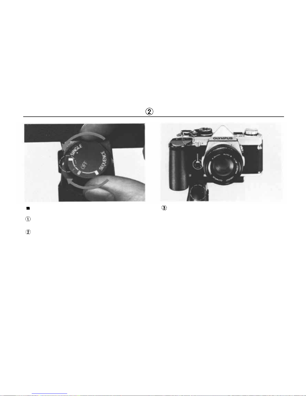
Unlock the shutter release lock lever on the
Control Grip.
Turn the mode selector on the Control Grip
to either "SINGLE" or "SEQUENCE". Set
the mode selector to the "OFF" position when
the Motor Drive 1 is not in use.
NOTE: In eith er mode, aut omatic exposure con-
trol is possible in the full range of shutter speeds,
and manual exposure is possible from 1 second to
1/1000 second.
Release the s hutt er.
NOTE: Y o u may use either the shutter release on
the Control Grip 1 or the shutter release on the
Motor Drive 1 to trigger the shutter.
39
Page 41
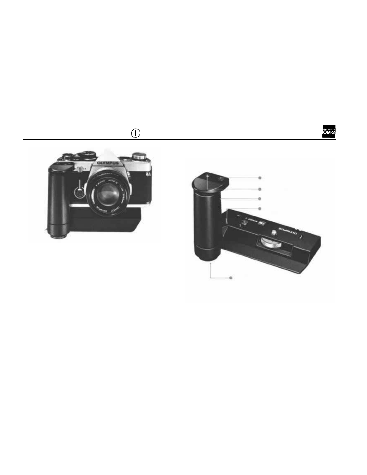
WINDER 2 OPERATION
Shutter Releas e
Remote Control Jac k
Non-Slip Finger Grip
Guide Pin
Winder 2
The unit provides the OM cameras with automatic
film winding capability for single-frame as well
as sequential filming (max. 2.5 frames p er second).
Mode Selector
40
Page 42
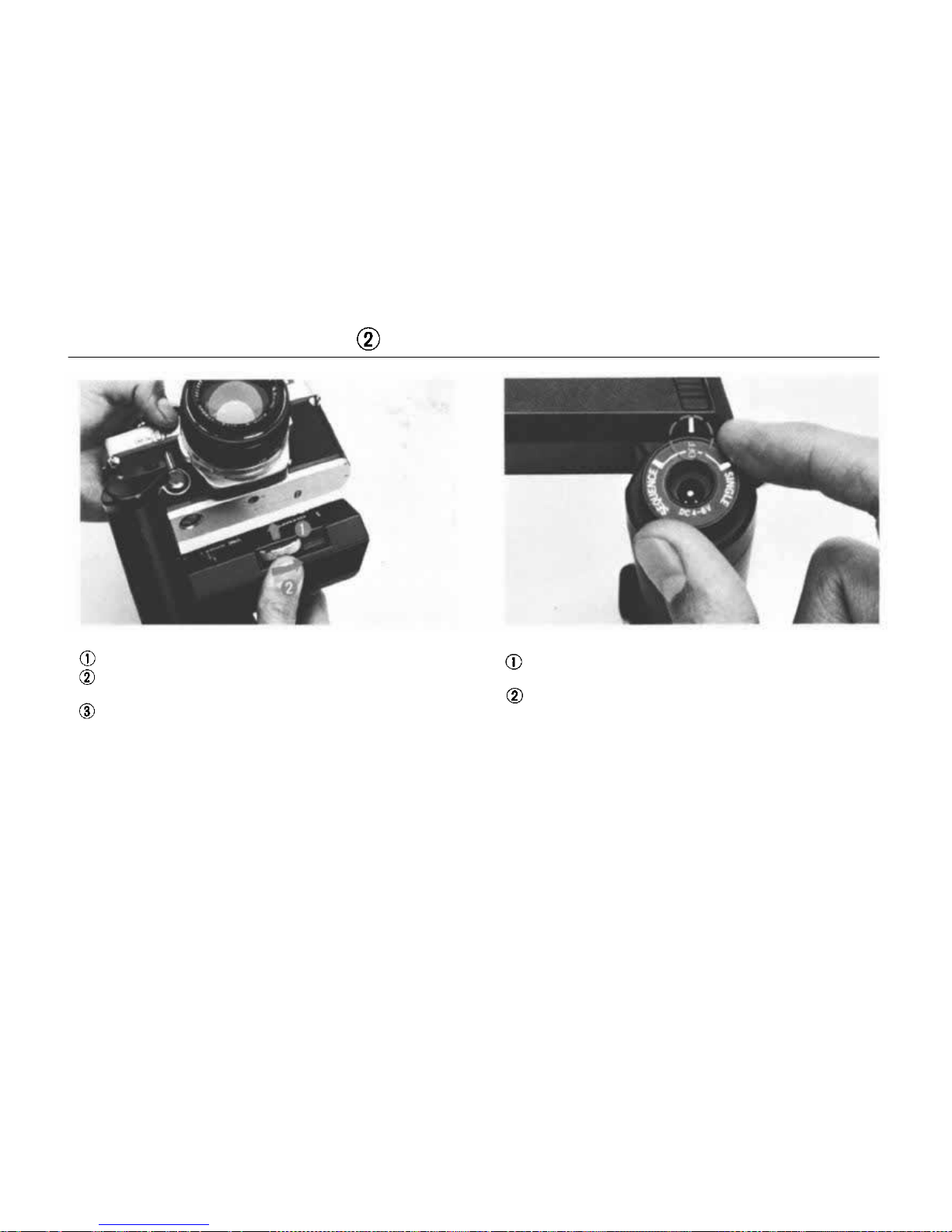
WINDER 2 OPERATION
Attaching the Winder 2
Remove the motor drive socket cap.
Pull up and rotate the mode selector to the
"OFF" position.
Remove the M. 6V Battery Holder 1 fro m in-
side th e winder, insert four 1.5V penlight (AA)
siz e batteries into the battery holder, and put
it back into the compartment. Insert the guide
pin into t he guide pin hole on th e camera base
plate. Turn the clamping screw clockwise until
the Winder 2 is securely attached to the cam-
era base plate.
Taking the pictures
Pull up and rotate the mode selector to the
"SINGLE" or "SEQUENCE" position.
Press the shutter release.
NOTE: The removed motor drive cap can be
stored in the socket cap storage positioned on the
underside of the battery holder com pa rt m en t.
41
Page 43

CARE AND STORAGE
General
Dust and moisture ar e harmful agents affecting
your camera. Remove the camera from the case
and store it in a dry, well-ventilated place making sure th e shutter and self-timer are free from
tension. Do not store the camera near moth balls
or similar volatile chemical materials to avoid
the possibility of damage to metal surfaces.
When storing the camera for a long period of
time, remove the battery. Wipe battery surfaces
with a dry cotton cloth before re-inserting into
the camera.
Avoid dropping or hitting the camera.
Never store the camera where temperatures ex-
ceed 50°C (122°F). When you use the camera
in temperatures under — 20°C (—4°F), it may
sometimes fail to operate properly. To avoid
this, warm the camera before use. Protect against
excess moisture by using packs of silica gel or
other desiccant in the storage area.
Af ter use near the ocean, wipe the camera sur-
faces clean with a soft cloth; never leave salt
on the camera. (Salt may be airborne near the
ocean and collect on the camera even though it
has not been in direct contact wi t h wa t e r.)
Avoid excessive tightening when mounting on
a tripod.
42
Page 44

Avoid areas exposed to corrosive chemicals,
radios, T V sets, or magnets.
Have all repairs performed by an authorized
OLYMPUS Service Center. You may send it
through the store where you bought your ca m-
era or directly to an Olympus Service Center.
Parts
Do not press the shutter release button at
random.
Do not touch any part that moves at high speed
such as the shutter, instant return mirror, diaphragm, etc.
Avoid touching the surfaces of the lens. Clean
only with an air blower, antistatic brush, or wipe
it lightly with a camel hair brush or lens tissue.
In EXTREME cases, use a clean, soft cotton
cloth moistened with denatured alcohol. NEV-
ER rub the lens surfaces with your finger, clothing, or other abrasive material.
If dust or fingerprints collect on the mirror,
focusing screen, or prism, take the camera to an
authorized OLYMPUS Service Center. It needs
professional attention.
43
Page 45

QUESTIONS & ANSWERS
Q: My camera is loaded wi th film. Why doesn't
the rewind knob rotate when I advance the
film?
A: The film leader may not be inserted in the
film take-up spool and th e fi lm is not ad-
vancing. (See page 9.)
Q: Wh y can't I advance the film?
A: The shutter may be cocked and ready to fire.
Try pressing the shutter release button. (See
page 10.)
Or, the film may be fully exposed. Check the
exposure counter. If you feel tension on the
film advance lever, DO NOT FORCE IT. Rewind the film. (See page 20.) Or the selftimer lever is not securely in its upright position,
reset
and
release
the
self-timer.
(See
page 21.)
Q: Why won't the shutter release button move
when I press it?
A: The film advance lever may not have been
fully advanced. (See page 9.)
Q: I can't advance th e f il m nor release the shut-
ter, and the viewfinder is totally dark. Why ?
A: The mirror is locked up because the batteries
are depleted or the film w a s advanced in the
middle of an automatic exposure. Press the
selector lever to the "CHECK•RESET"position to unlock the mirror. (See page 8.) Two
batteries should be replaced as a pair if they
are depleted.
Q: Why won't the rewind crank turn when I try
to rewind the film?
A: The rewind release lever may not be rotated
in the arrow direction until it aligns with the
"OM-2" marking. (See page 20.)
Q: Why can't I set the ASA fi lm speed I need?
A: At the most, 3 stops can be advanced in a
single stroke of the dial. If you require more
stops, lift up and rotate the outer collar of
the
dial
until
it
stops;
then
release
the
collar
and
reverse
the
collar
and
dial
together
until
the white line is aligned with the black index
on the pentaprism. Repeat this procedure
until you reach the ASA speed you need.
(See page 11.)
44
Page 46

Q: What batteries should I use?
A: Use two 1.5V silver oxide batteries SR44
(Eveready EPX-76 or equivalents). Never
use 1.3V mercury batteries (though they
ar e th e sam e s i ze ) . (Se e page 7. )
Q: Wh y doesn't the battery chamber cap fit?
A: If you also own an OM-1, you may have the
caps mixed up. Although they look alike,
the OM-2 cap has "2" engraved inside.
Q: When should I check the batteries?
A: (1) When new batteries are inserted. (2)
After the camera hasn't been used f or a long
time. (3) Before beginning a prolonged
period of use.
Q: Can film be properly exposed when the selec-
tor lever is in the "OFF" position?
A: The OM-2 is designed to always expose the
film 1/30 second or faster (ASA 100) with
the selector lever at the OFF position. If the
shutter is unintentionally released in darker
condition on "OFF" mode, the exposure
automatically stops in approx. 1/30 second
(ASA 100) to save unnecessary battery ex-
haustion.
Q: Can I set the shutter speed ring to any posi-
tion t o ta ke pictures on A U TO mode?
A: Any position except "B".
Q: Wh y is the automatic exposure shutter speed
much longer than indicated by the meter in
the viewfinder?
A: If film is not loaded, the shutter speed is
much longer than that indicated. If it is
necessary to obtain a correct reading without actually taking a picture, insert a waste,
undeveloped fil m or the paper yo u f i n d b ehind the camera back at the purchase of your
OM-2, into the film position in the camera.
Q: Can I use the exposure compensation dial
when the selector lever is set at the "MAN-
UAL" position?
A: Yes. If the exposure compensation dial is
set for an intentional over- or under-exposure, that over- or under-exposure will be
achieved when the shutter speed/F stop
combination centers the meter needle between the over- and under-exposure index
marks in the viewfinder. (See page 24.)
45
Page 47

Q: How can I remove dust from inside the view-
finder?
A: After detaching the Focusing Screen, blow
away any dust with an air blower. Never
wipe
the
screen
surface
with
cloth
or
paper.
(See page 28.) If this does not solve the pro-
blem, send your camera to an authorized
OLYMPUS Service Center.
Q: Is it normal fo r the microprism in the center
of the viewfinder to "shimmer" and darken?
A: Yes, when a lens with a maximum aperture
smaller than F5.6 is mounted on the camera.
It also happens with other lenses when the
depth of field preview button is pressed.
Q: Why does the self-timer stop halfway with-
out releasing the shutter?
A: The lever will stop without releasing the shut-
ter if the film has not been fully advanced.
Reset the self-timer and make sure the film
is fully advanced. The self-timer lever moves
freely because you forget to turn the start
lever after you set the self-timer lever. (See
page 21.)
Q: Can I operate the camera without the motor
driv e socket cap in place?
A: No. Light will enter the camera body through
this hole, fogging the film. Also, dust and
dirt
may
enter,
causing a camera
malfunc-
tion.
Q: Why doesn't my electronic flash unit fire
when I release the shutter?
A: If the sh utter speed is 1 /12 5 second or fast er
in conjunction with the electronic flash T32
or T20, the built-in incorrect flash prevention
system does not permit flashing. Confirm
the shutter speed. ( See page 31 . )
Q: Why do I feel a small electrical shock w hen
I touch the terminal contact of the accessory
shoe?
A: This is normal when using a side-mounting
type flash. When using flash that is not connected to the accessory shoe, remove or
cover the shoe.
46
Page 48
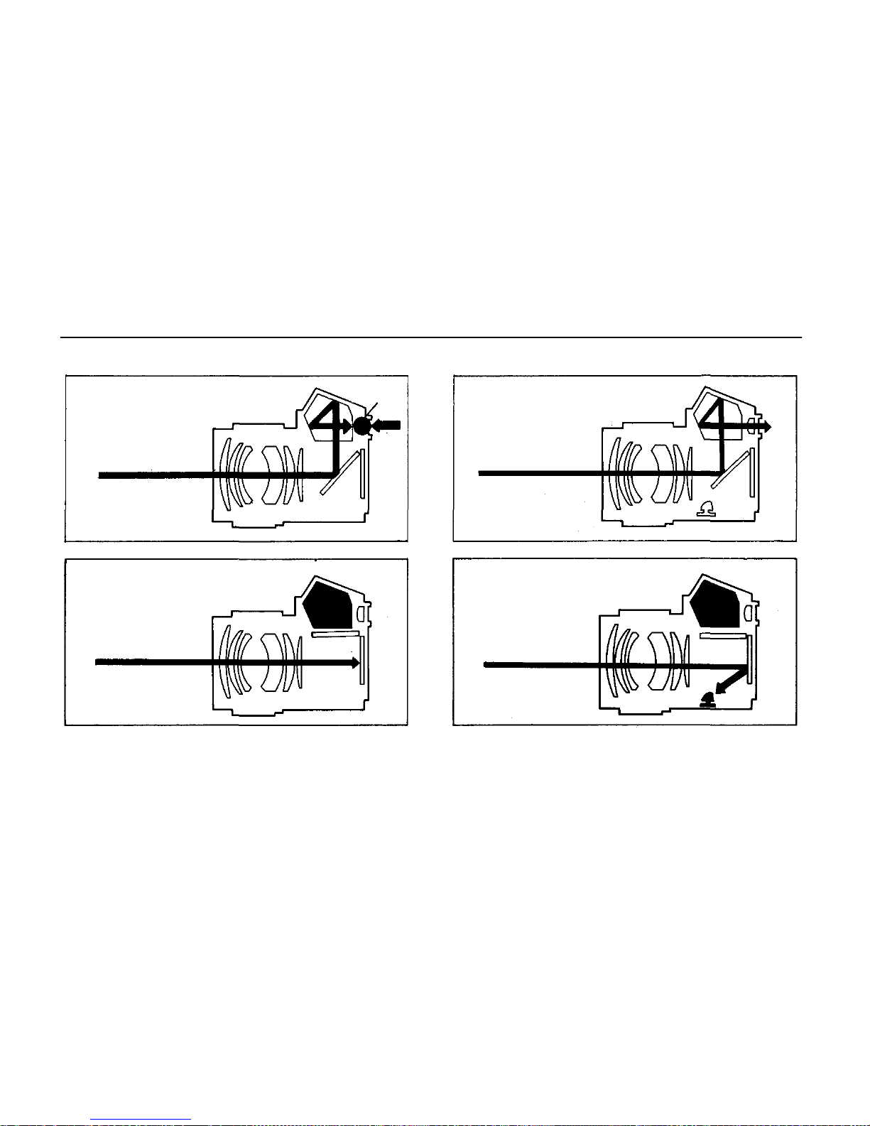
THE MOST IMPORTANT FEATURE OF THE OM-2-TTL DIRECT(OTF)LIGHT
Diagram of light path in conventional SLRs Diagram of light path in OM-2
Before shutter release
The instant the shutter has
been re leased
(A memory device controls
the shutter speed, based on
the light reading taken before
actual exposure.)
In the automatic mode, the OM-2 measures the
subject brightness very differently from any other
automatic camera — faster and with much more
accuracy. With the OM-2, light entering the lens
is measured directly at t he fi lm plane by the sen-
The instant the shutter has been released
sor s at th e precise moment the f i lm i s being ex posed. W he n su fficient light h a s reached the film,
the electronic brain senses the infor mation and
instantly closes the shutter.
Light Sensor
Position
Before shutter release
Stray
Light
Light Sensor Position
47
MEASURING
Page 49
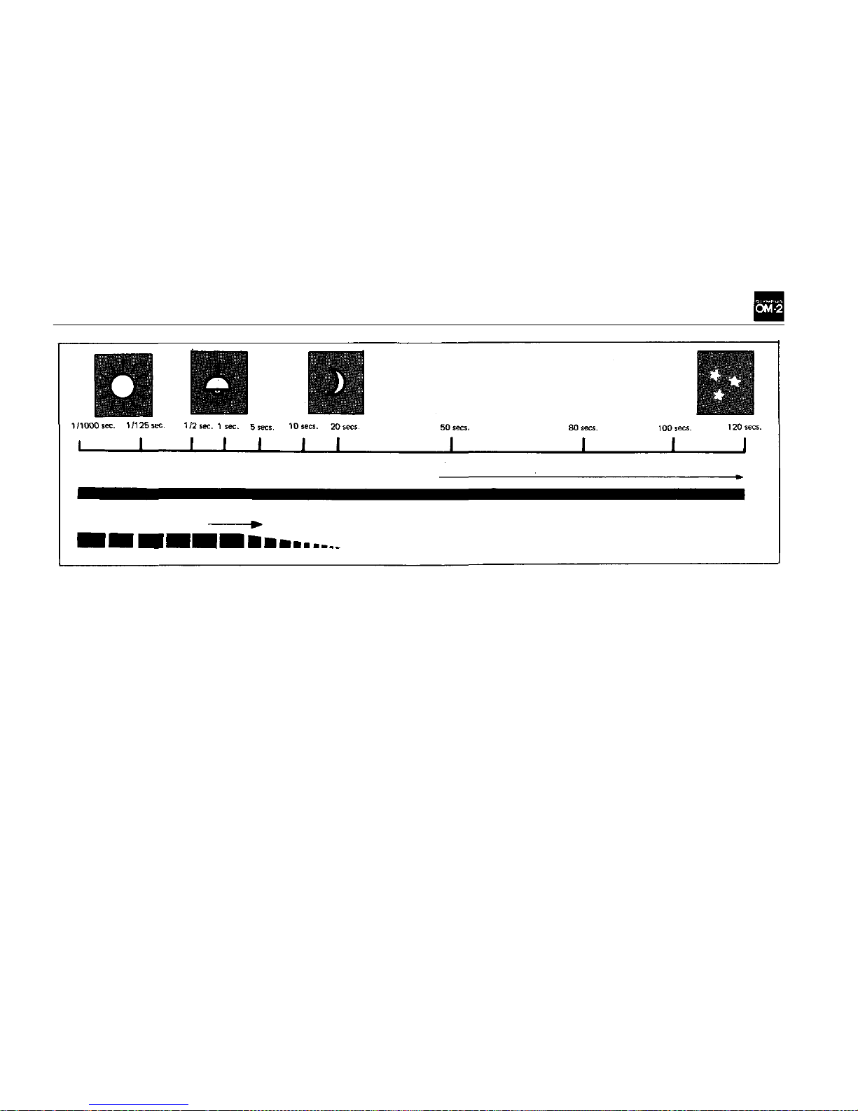
Exposure range of O M-2 in automatic mode
Shutter Speed a t F1 .2
Exposure range of conventional
AE SLRs
Advantageous Points of Through-The-Lens Direct
(off-the-film) Light Measuring Method
1. The OM-2 sensors respond instantly to changes
in the light during exposure and feed back the
information to the shutter control mechanism.
2. The sensors measure flash intensity as it builds
up and cu t of f i t s light a t t h e source when the
correct exposure level is reached. (TTL Centralized Control Flash)
3. Even during 5-frame-per-second motor drive
operation, this Method insures correct ex-
posure fo r each frame individually.
4. The Method operates accurately in far dimmer
light than other systems. ASA 100 film can
be automatically exposed for up to 120 seconds at F1.2.
5. The Method excludes all possibilities of stray
light leaking through the camera eyepiece and
affecting the exposure reading.
6. The Method gives correct exposures even when
the clear-field type focusing screen is in use.
48
Page 50
Page 51

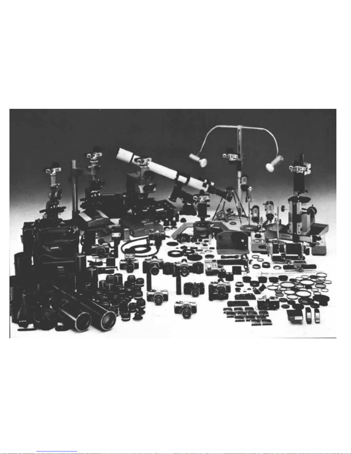
OM SYSTEM
The OM System is comprehensively arrayed to
meet an ever-expanding universe of photographic
conditions for any subjects from the stars to micro-
organisms.
A full-scale system camera is distinguishable by
some of the prerequisite characteristics as broad-
ly mentioned below:
• Interchangeability of focusing screens.
• Adaptability to high speed mot or drive photography.
• A wide range of high quality system components, includ ing interchangeable lenses.
• Compatibility of the camera body with an
electronic flash unit allowing high technic
flash
photography
with
extreme
ease
and
accuracy.
• Tough and reliable shutter, viewfinder, etc.
that withstand harsh handling without fai ling.
When these exacting conditions have been satis-
fied, an OM-2 is b or n a s a true system camera th at
controls an entire SLR comprehensive system. The
OM-2 is backed up with over 300 components
systematically organized under eight groups — In-
terchangeable Lens, Finder, Flash, Motor Drive,
Phototechnical, Macrophoto, Photomicro and
Case.
50
Page 52
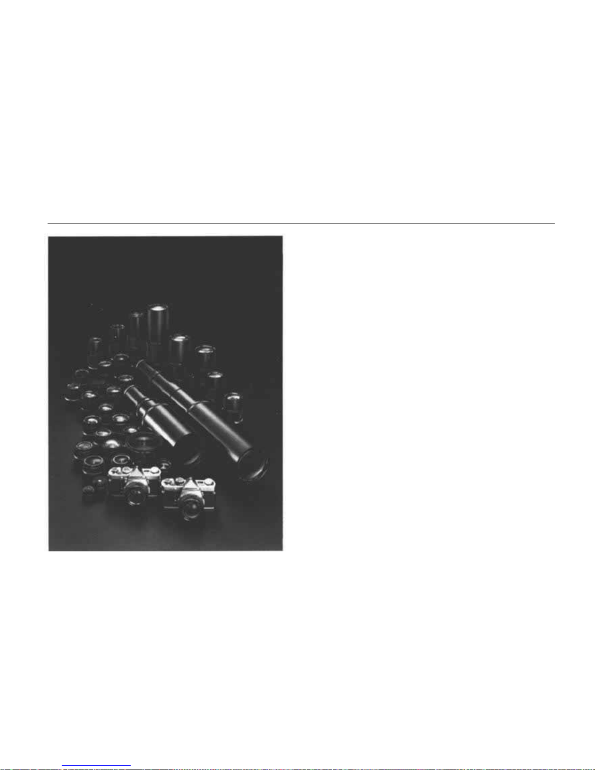
ZUIKO INTERCHANGEABLE LENS GROUP
One of many advantages of the single lens reflex
camera is the large variety of interchangeable lens-
es available. The Zuiko Interchangeable Lens
Group (designed and manufactured by Olympus)
comprises 33 lenses. Z uiko lenses have always en-
joyed a high reputation in photographic circl e s —
the most modern design technology and employment of newly developed optical glass have made
possible a new series of innovative, high performance lenses. These lenses have a host of special
features including new construction that compensates for close focus aberrations, increased ape rture ratio in the wide angle lenses, and reduction
in telephoto lens size and weight. The OM System adopts 49mm filters for most lenses from
21mm to 200mm. As part of the OM System
design all the lenses now offer higher performance in small configurations. Olympus has produced lenses for microscopes for decades and
the new Zuiko lenses benefit fr om th is scientific
experience. See the "OM System Zuiko Interchangeable Lenses" manual for further information.
51
Page 53
Page 54
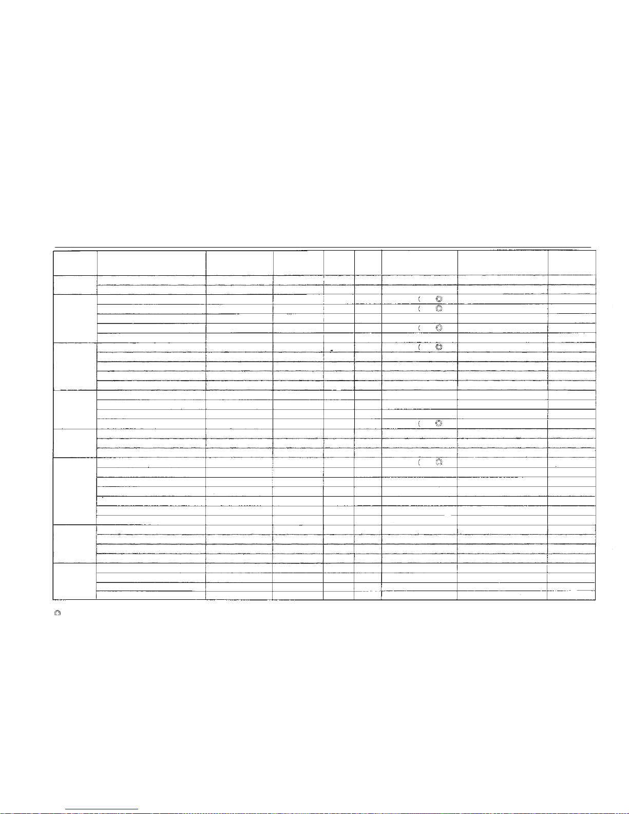
TABLE OF INTERCHANGEABLE LENSES
TYPE
FISHEYE
SUPER WIDE
WIDE
STANDARD
ZOOM
TELEPHOTO
SUPER
TELEPHOTO
SPECIAL
USE
INTERCHANGEABLE LENSES
ZUIKO FISHEYE
ZUIKO FISHEYE
ZUIKO MC
ZUIKO MC
ZUIKO
ZUIKO MC
ZUIKO
ZUIKO MC
ZUIKO
ZUIKO MC
ZUIKO
ZUIKO SHIFT
ZUIKO
ZUIKO MC
ZUIKO
ZUIKO MC MACRO
8mm
F2.8
16mm
F3.5
18mm F3.5
21mm
F2
21mm F3.5
24mm F2
24mm F2.8
28mm F2
28mm F3 .5
35mm F2
35mm F2.8
35mm F2.8
55mm F1.2
50mm F1.4
50mm F1.8
50mm F3.5
ZUIKO MC ZOOM 35-70mm F3.6
ZUIKO ZOOM 75-150mm F4
ZUIKO MC ZOOM 85-250mm F5
ZUIKO MC
ZUIKO
ZUIKO MC
ZUIKO
ZUIKO MC
ZUIKO MC
ZUIKO
ZUIKO
ZUIKO MC
ZUIKO MC
ZUIKO MC
ZUIKO MC MACRO
ZUIKO MC MACRO
85mm F2
100mm F2.8
135mm F2.8
135mm F3.5
180mm F2.8
200mm F4
200mm F5
300mm F4.5
400mm F6.3
600mm F6.5
1000mm F11
20mm F3.5
38mm F3 .5
ZUIKO MC 1:1 MACRO 80mm F4
ZUIKO MC MACRO
135mm F4.5
ANGLE OF VIEW
180°(circle)
180°
100°
92°
92°
84°
84°
75°
75°
63°
63°
63° (83° at max shift)
43°
47°
47°
47°
64° ~ 34°
32° ~ 16°
29° ~ 10°
29°
24°
18°
18°
14°
12°
12°
8°
6"
4°
2.5°
9° at highest mag.
9° at highest mag.
9° at highest mag.
18°
OPTICAL
CONSTRUCTION
ELEMENT-GROUP
11–7
11–8
11–9
11–9
7–7
10–8
8–7
9–8
7–7
8–7
7–7
8–6
7–7
7–6
6–5
5–4
10–8
15–11
15–11
5–4
5–5
5–5
5–4
5–5
5–4
6–5
6–4
5–5
6–4
5–5
4–3
5–4
6–4
5–4
DIAPHRAGM
AUTO.
AUTO,
AUTO.
AUTO.
AUTO.
AUTO.
AUTO.
AUTO.
AUTO
AUTO.
AUTO.
MANUAL
AUTO.
AUTO.
AUTO.
AUTO.
AUTO,
AUTO.
AUTO.
AUTO.
AUTO.
AUTO.
AUTO.
AUTO.
AUTO.
AUTO.
AUTO
AUTO.
AUTO.
AUTO
MANUAL
MANUAL
AUTO.
AUTO.
F STOP
RANGE
2.8-22
3.5-22
3.5-16
2-16
3.5 16
2-16
2.8-16
2-16
3.546
2-16
2,8-16
2.8-22
1.2-16
1.4-16
1.8-16
3.5-22
3.6-22
4-22
5-32
2-16
2.8-22
2.8-22
3.5-22
2.8 32
4-32
5 32
4 5-32
6.3-32
6.5-32
11-45
3.5-16
3.5-16
4-32
4.5-45
MIN. FOCUS
(meters) (ft.)
0.2 m
0.2 m
0.25m
0.2 m
0,2 m
0.25m
0.25m
0.3 m
0.3 m
0.3 m
0,3 m
0.3 m
0.45m
0.45m
0.45rn
0.23m
08 m
1.6 m
2 m
0.85m
1 m
1.5 m
1.5 m
2 m
2.5 m
2.5 m
35 m
5 m
11 m
30 m
(0 7)
(0.7)
0.8)
0.8)
(0.7)
0.8)
(0.8)
(1.0)
(1.0)
(1.0)
(1.0)
(1.0)
(1.5)
(1.5)
(1.5)
0.8)
(2.7)
(5.2)
(6.0)
(2.8) .
(3.3)
(4.9)
(4.9)
(6.0)
(8.2)
(8.2)
(11.5)
(16.4)
(36.1)
(98.4)
W/Auto Bellows & PM-MT ob
W/Auto Bellows & PM-MT ob
W/Auto Bellows or 65-116
W/Auto Bellows or 65-116
MIN. FIELD
30×20cm
21×14cm
21×14cm
23×15cm
23×15cm
27×18cm
27×18cm
21×14cm
21×14cm
21×14cm
23×15cm
24×16cm
24×16cm
72×48cm
72×43cm~25×37.5cm
64×42cm~32×21cm
66×44cm~23×15cm
29×19cm
29×19cm
32×21cm
32×21cm
32×21cm
36×24cm
36×24cm
33×22cm
36×24cm
55×37cm
98×65cm
max.
8 × 5 mm mm. 3 × 2 mm
max.
20 × 13mm m i n .
6 × 4
mm
max. 72 × 48mm min. 18 × 12mm
72×48mm
WEIGHT (o z .)
640g(22.6)
180g (6.3)
250g (8.8)
250g (8.8)
180 g (6.3)
280g (9.9)
18 0 g (6.3)
250g (8.8)
180g (6.3)
240g (8.5)
180g (6.3)
310g(10.9)
310g(10.9)
230g (3.1)
170g (6.0)
200g (7.1)
420g(14.8)
440g(15.5)
890g(31.4)
260g (9.5)
230g (8.1)
360g(12.7)
290g(10.2)
700g(24.7)
510g(18.0)
380g(13.4)
1100g(38.8)
1300g(46.0)
2800g(98.8)
4000g(141.0)
70g (2.5)
90g
(3.2)
170g (6.0)
320g(11.3)
MC stands for multicoating.
A
a
n
naan
an
a
a
n
53
Page 55
LENGTH
82mm
42mm
43.5mm
31mm
48mm
31mm
43mm
31mm
42mm
33mm
58mm
47mm
39mm
31mm
40mm
74mm
196mm
48mm
48mm
80mm
73mm
124mrn
127mm
105mm
181mm
255mm
377mm
662mm
20mm
28mm
33mm
47mm
MAX.
DIAMETER
102mm
59mm
62mm
60mm
59mm
60mm
59mm
60mm
59mm
60mm
59mm
68mm
65mm
60mm
59mm
60mm
67mm
63mm
70mm
60mm
50mm
61mm
60mm
80mm
67mm
62mm
80mm
80mm
110mm
110mm
32mm
43mm
59mm
60mm
HOOD
———
———
49 72mm Screw-in
55mm Slide-on
49mm Screw-in
55mm Screw-in
49mm Screw-in
49mm Screw-in
49mm Screw-in
55mm Screw-in
51mm Slide-on
49mm Slide-on
57mm Slide-on
51mm Slide-on
51mm Slide-on
——
60mm Slide-on
Built-in
Built-in
49mm Screw-in
49mm Screw-in
Built-in
Built-in
Built-in
Built in
Built-in
Built-in
Built-in
Built-in
BuiIt-in
——
——
——
57mm Slide-on
FILTER
Built-in
Built-in
72mm
55mm
49mm
55mm
49mm
49mm
49mm
55mm
49mm
49mm
55mm
49mm
49mm
49mm
55mm
49mm
55mm
49mm
49mm
55mm
49mm
72mm
55mm
49mm
72mm
72mm
100mm
100mm
21mm Slide-on
32mm Slide-on
49mm
55mm
Compatible : The
meter needle indi-
cates correct light read-
ings. In the combination
marked with *, m icr o-
prism, split-prism and
edges of the finder
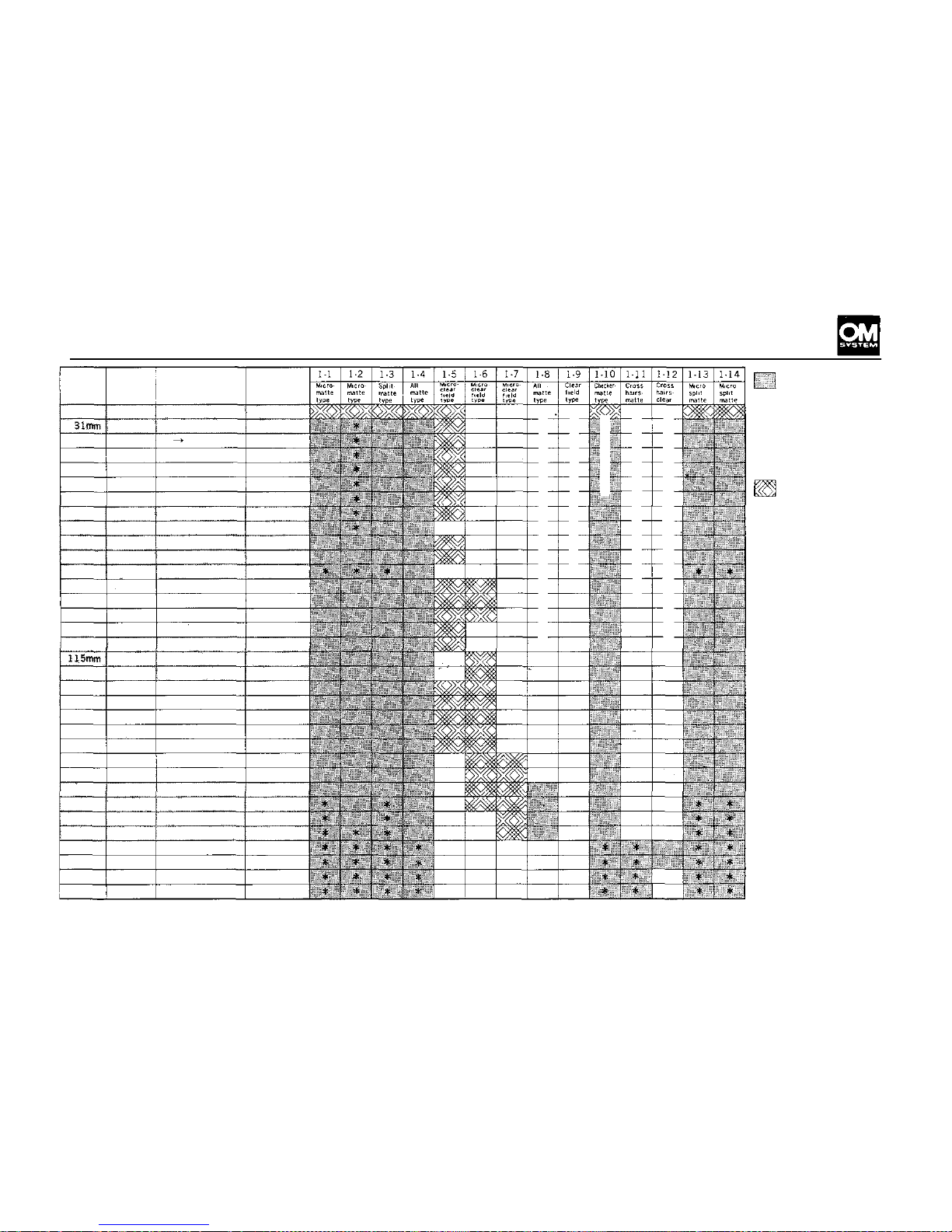
will darken.
Compatible: The
meter in the OM-1
and OM-2 (on MANUAL)
cannot be used. On
AUTO, the OM-2 m ak es
correct exposures, but
the meter needle does
not indicate correct
shutter speeds.
(Specifications subject
to change without
notice.)
FOR
TELEPHOTOGRAPHY
&
ASTROPHOTOGRAPHY
FOR
ENDOSCOPIC
PHOTOGRAPHY
FOR
SHIFT
LENS
FOR
CLOSE-UP
&
MACROPHOTOGRAPHY
FOR
MACROPHOTOGRAPHY
&
PHOTOMICROGAPHY
54
Page 56
INTERCHANGEABLE LENS GROUP UNITS
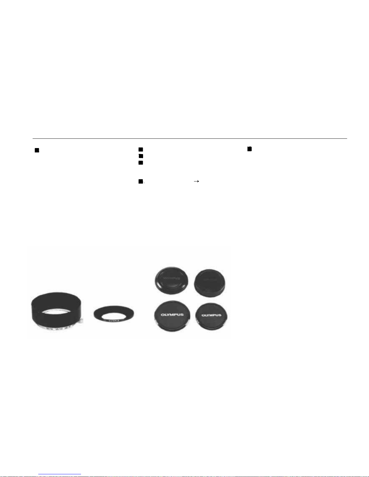
Lens Hoods
Lens hoods protect against extraneous light striking the lens
and causing unwanted glare.
Hoods for standard lenses are
cover types and can be reversed
to provide easy storage even
when the camera is in the case.
Five lens hoods are optionally
available (see TABLE OF INTERCHANGEABLE LENSES
on p p . 53-54).
Camera Body Cap
Rear Lens Cap
Front Lens Caps
(49mm, 55mm, 72mm and
100mm in diameter)
Adapter Ring 49 72mm
A lens hood/filter mount for the
18mm F3.5 lens.
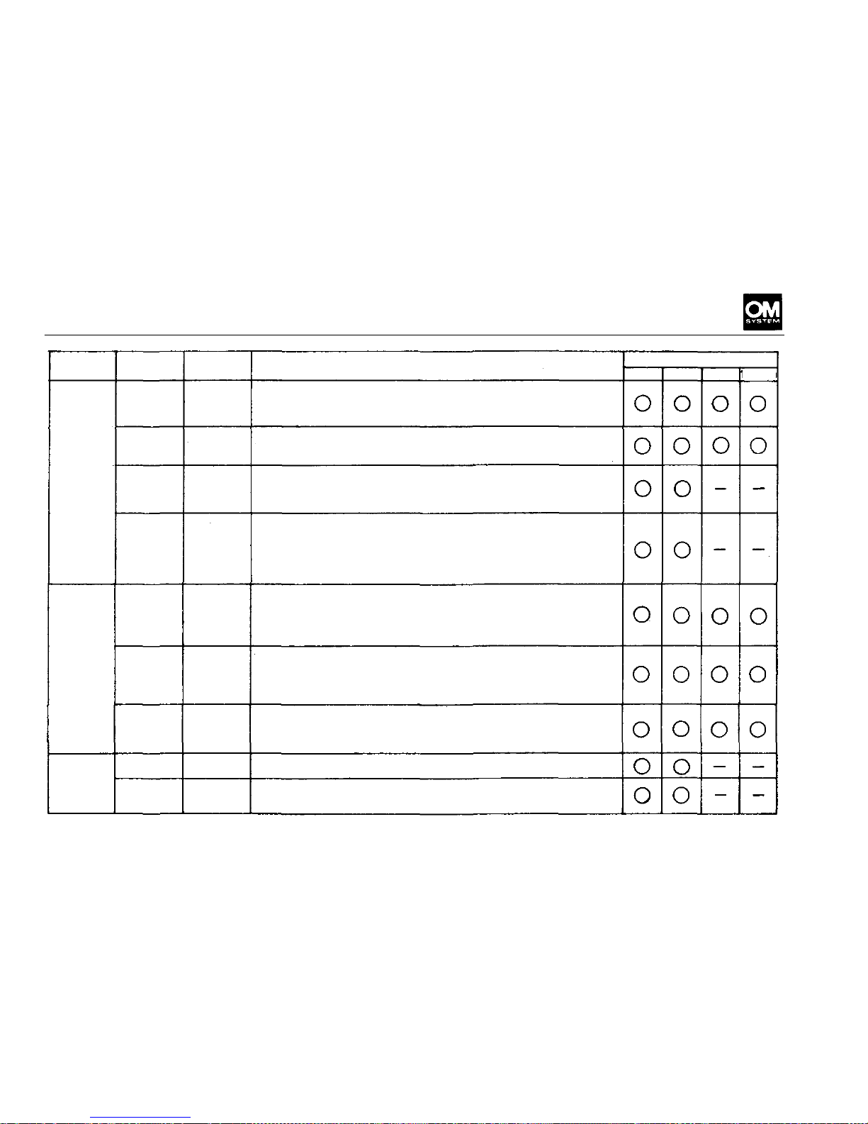
Filters
Filters are essential to the e ffec-
tive rendition of photographic
subjects. In controlling contrast
and eliminating unwanted haze
in black and white photography,
the use of the correct filter often
means the difference between a
goo d photograph an d a great one.
In color, where the balancing of
the light with the film emulsion
is absolutely necessary for cor-
rect color, conversion and light
balancing filters are the only ef-
fective way of achieving the de-
sired results.
* Be careful not to us e two filters
simultaneously in order to avoid
unintentional cut in the per-
iphery of a photograph.
(See the table of various filters
on the opposite page.)
55
Page 57
Application
B. & W.
and
Color
B. & W.
Color
Name
Skylight
(1A)
L39
(UV)
ND2
ND4
Polariz-
ing filter
POL
Y48
(Y2)
056
(02)
R6CMR1)
A4
(81C)
B4
(82C)
Color
Colorless
Colorless
Grey
Grey
-
Yellow
Orange
Red
Amber
Blue
Description
Similar to UV filter. Eliminates ultraviolet rays. Reduces haze and bluish tones in daylight photography.
Effective with color film only. May be used at all times
to protect the lens.
Eliminates
undesirable
ultraviolet
rays
which
cause
dull,
flat pictures. Renders subject i n clear detailed b rilliance.
May be used at all times to protect the lens.
Reduces the quantity of light entering the lens to 1/2
or 1/4 of the original intensity. For use in extremely
bright conditions when you wish to maintain a wide
aperture.
Enables you to take pictures through glass or water
without reflections. Will darken the sky in black-andwhite photographs without altering other color values
in the picture, and renders blue skies darker when used
with color film. Reflections are reduced to provide
better texture surface detail.
Accentuates contrast, darkens blue skies. Very effective
in daylight scenes where the sky is part of subject matter. Heightens the effect of white clouds. Usefull in
copying documents where line copy is blue or black
on li ght background.
Absorbs a wider range o f wav ele ngt hs f ro m UV to dark
green than the Y2 . Makes a superb rendition of the texture of outdoor subjects, and indoors. It brings but
detail in objects yellow, brown. Used with infrared
film.
Used as contrast filter to create darkened sky or in copy-
ing. Also used to penetrate haze in landscape photography for stronger contrast than an O2 filter. Used
wit h infrared film.
For use when taking color pictures in cloudy or rainy
weather. Reduces bluish tone.
Designed for use when taking color pictures in early
morning or late evening hours when red rays are pre-
dominant.
49mm
Diameter
55mm
72mm
100mm
56
Page 58
FINDER GROUP
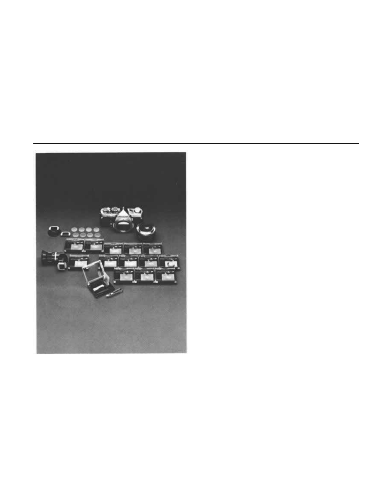
The viewfinder is one of the most important features of a single lens reflex camera. Since every
photographic subject is turned into a visual image
by means of the finder, a finder that is dark or
difficult to look through is an obstacle to good
photography. However enriched an SLR camera
is with a wide range of interchangeable lenses, the
SLR cannot be expected to fulfill its essential function without the provision for changing of focus-
ing screens. The OM-2 is provided with a viewfinder that offers a far brighter, large image than
previous 35mm SLR cameras. The Finder Group
supplements this basic advantage with a compre-
hensive set of 14 focusing screens for a wide variety of applications from photomicrography to astrophotography. Unless the most suitable focusing
screen for a given photographic purpose is available, the potentialities of a system camera cannot
be utilized. For fast, accurate focusing, the OM
System Finder Group offers the unique Vari-
magni Finder with a magnification selector, the
Eyecup 1 that accepts a variety of Dioptric
Correction Lenses, Eyecoupler, etc.
57
Page 59
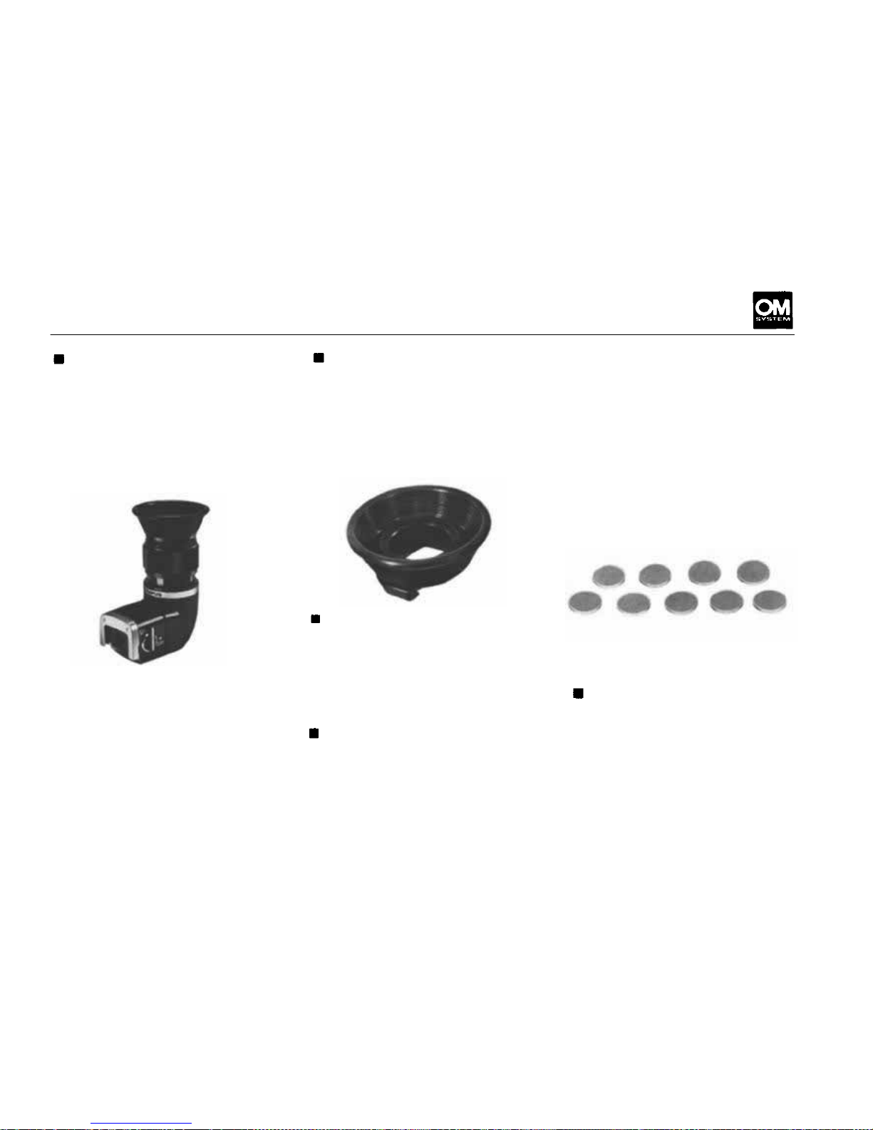
FINDER GROUP UNITS
Varimagni Finder
This unique and exclusive unit
for the OM System combines
the two functions of angle finder
and magnifier, incorporating 9
lens elements and a reflector. It
fits over the camera's eyepiece,
and can be adjusted for indi-
vidual eyesight. Its eyepiece tube
is rotatable through 360°, for
use in low level and 90° angled
shots. The two-stage, one-touch
switching system offers both a
1.2x magnification image cover-
ing the whole screen, and a 2.5x
enlargement of the central por-
tion for critical focusing. For
photomicrographic use, insert
the Eyecoupler between the carp-
era a nd Varimagni Finder.
Eyecup 1
Attached by sliding over the OM
Body eyepiece. Its rubber hood
prevents stray light from entering
through the eyepiece, an essen-
tial requirement in light measur-
ing. The Eyecup 1 is provided
with a slot for Dioptric Correc-
tion Lenses.
Eyecoupler
Connects the Varimagni Finder
to the OM Body for photomicro-
micrography.
It
also
ensures
full
coverage of the bright viewfinder
field fo r use of the Eyecup 1 in
conjunction with the Motor
Drive 250 Film Back.
Focusing Screen 1
Interchangeable Focusing Screens
are often thought of as a luxury
feature in 35mm photography.
Yet the Standard Focusing
Screen 1-13 is often inconvenient
or difficult to use, and, in so me
circumstances it is quite unsatisfactory. With super-telephoto
lenses for instance, the micro-
prism becomes excessively dark.
With the high magnifications of
macrophotography and photomicrography, it is impossible to
focus.
The feature of each Focusing
Screen is listed on pp. 59—60.
Dioptric Correction Lens 1
Available in 8 diopter correc-
tions: + 2, +1, 0 (for hypermetro-
pia);
-1, -2, -3, -4, -5
(for
myopia). Used to match the
photographer's vision, and especially necessary in fine focusing
for high magnification. Fits into
the Eyecup 1.
58
Page 60
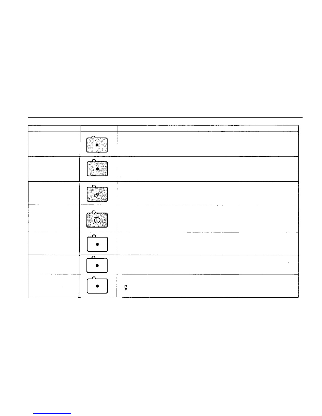
FINDER GROUP UNITS
TYPE
1-1
Microprism-matte
type
(for most lenses)
1-2
Microprism-matte
type
(for standard &
telephoto lenses)
1-3
Spli t image-mane
type
(for most lenses)
1-4
All matte type
(for most lenses)
1-5
Microprism -clear
field type
(for wid e angle &
standard lenses)
1-6
Microprism-clear
field type
(for standard &
telephoto lenses)
1-7
Microprism-clear
field type
(fo r super
telephoto lenses)
FEATURES
Standard type, suitable for general photography. Fast and accurate
focusing is done on the central microprism spot as well as on the surrounding matte area. When a lens with a maximum speed of F 5.6 or
slower is used, the microprism darkens and focusing must be made
on the matte area. The meter needle indic ates proper exposures.
Suitable for general photography in conjunction with a standard or
telephoto lens. Focusing is done on the microprism spot as well as
on the
matte
area.
When a lens
with a maximum
speed
of F8 or
slower
is used, the microprism spot darkens. The meter needle indica t es prop-
er exposures.
Suitable for general photography ensuring critical focusing, and ideal
for photographers who prefer the split-field and coincidence type
focusing. When a lens with a maximum speed of F5.6 or slower is
used, the split prism darkens. The meter needle indicates proper ex posures.
Suitable for general photography and ideal for photographers who
prefer a view field free from microprism or split prism and fo r those
who are accustomed to focus using matte area. Also suitable for super
telephoto photography and close-up photography in conjunction
with
macro
lenses
and
Auto
Bellows.
The
meter
needle
indicates
proper exposures.
This transparent screen provides an exceptionally brig ht f ind er i mage.
Highly suitable for snapshots using wide angle lenses. The lack of
matte surface means depth-of-field effects cannot be ascertained.
The meter needle does not indicate proper exposures, because its
movement varies depending on the lenses used.
This screen provides an extremely bright finder image. Focusing is
done on the microprism spot. The lack of matte surf ace means depth
of-field effects cannot be ascertained and the meter needle does not
indicate proper exposures.
Developed primarily for use with super telephoto lenses, this clear
field screen provides an extremely bright finder image. The micro-
prism spot remains bright even with a lens whose maximum speed is
11. The lack of matte surface means depth-of-field effects cannot
be ascertained, the meter needle does not indicate proper exposures.
SCREEN
59
Page 61
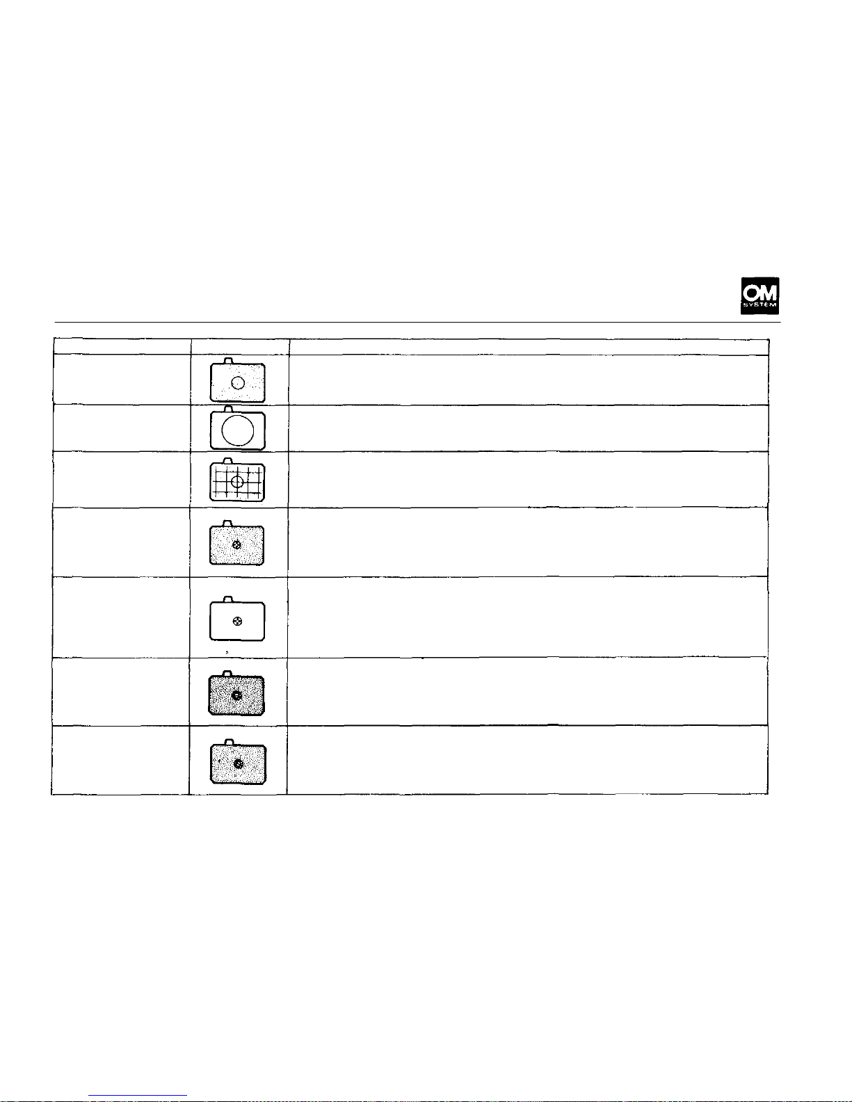
TYPE
1-8
All matte type
(for telephoto lenses &
astronomical telescopes)
1-9
Clear field type
(for endoscopic
photography)
1-10
Checker-matte
type
(for Shift lens)
1-11
Cross hairs-matte
type
(for close-up &
macro-
photography)
1-12
Cross hairs-clear
field type
(for photomicrography
& macrophotography
greater
than
life
size)
1-13
Microprism/split
image-matte
(for most lenses)
1-14
Microprism/split
image-matte
type
(for most lenses)
SCREEN
FEATURES
This
screen
is
ideal
for use
with
super
telephoto
tenses
of
300mm
or
more in focal length, or for astrophotography. The extreme fineness
of the matte surface permits outstanding field definition. More accurate focusing may be achieved by the u se o f the Varimagni Finder.
Designed for use with OLYMPUS fiberoptic endoscopes. Thi s condenser type screen without fresnel lens requires no focusing when
a special adapter couples the camera with the fiberscope. Exposure
is made aut oma tic all y by the light supply.
The grid lines engraved on the all-matte surface are used for vertical
and horizontal picture alignment. Though originally designed for
architectural
photography
with
the
Shift
lens,
it is
also
suitable
for
general and super-telephotography, and close-up/macrophotography
with
macro
lenses
and
Auto
Bellows.
Highly advantageous for clos e-up and macrophotography with Auto
Bellows and extension tubes. For focusing in low magnification close-
up photography, use the matte area and in macrophotography greater
than li fe size, use the double cross hairs t he sa m e w ay as wi th th e 1 -1 2 .
The meter needle indicates proper exposures, but depending on the
conditions of the specimen, the reading must be compensated for.
The
transparent
screen
offers
the
photographer
focusing
with
an un-
usually bright finder image. To focus, first correct your diopter
using a dioptric correction lens or Varimag ni Finder so that each
line of the double cross hairs can be seen clearly and separately.
Then bring the specimen into focus. The meter needle indicates
proper exposures, but depending on the specimen's conditions, the
reading must be compensated for.
Most
suitable
for
normal photography,
this
screen
assures
pinpoint
focusing. The central split image rangefinder is encircled by a microprism collar. Since the outer area has a matte surfac e, the screen can
be used in the same w ay as the standard 1-1 and 1-3 Screens. When a
lens with a maximum speed of F5.6 or slower is used, the prisms
darken and the focusing must be made on the matte area.
Most suitable for normal photography. The central split-image range
finder, encircled by a microprism collar, is inclined 45 degrees to allow
easy
focusing
on
subjects
with
vertical
or
horizontal
lines.
When
a
lens with a maximum speed of F5.6 or slower is used, the prisms
darken and focusing must be made on the matte area. The meter
needle gives correct light readings.
60
type
Page 62
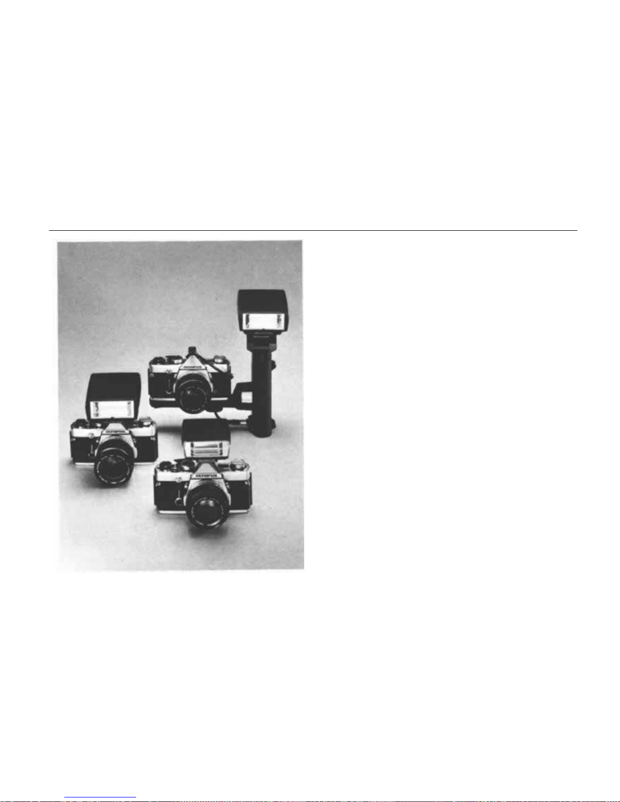
FLASH PHOTO GROUP
Flash is your own private "sun" when you take
pictures at night, indoors, or outdoors for day-
light fill-in. A t the moment of flash , you can even
catch the movement of subjects that your own
eyes are unable t o follow.
At present the OM System Flashphoto Group renders choice of 5 different flash units, including
the Electronic Flash T32 and T20. TheT32 offers
high performance — a maximum ASA 100 guide
number of 32 ( in meters) or 104 (in feet) with an
angle that virtually covers the picture area of a
24mm s u p er - w i d e angle lens, and is provided with
a built-in bounce mechanism. The T20 is extreme-
ly compact and features a maximum ASA 100
guide number of 20 (in meters) or 66 (in feet)
with an angle that covers the picture area of a
35mm wide angle lens. The T32 (o r T20), when
used wit h the OM-2, is an OTF (off-the-film) ful-
ly automatic electronic flash unit. Even the dial
settings (auto/manual switching, aperture setting
and ASA film speed setting) required of conven-
tional
"auto"
flash
units
are
unnecessary.
By re-
versing
the
back
plate
of the
flash
unit,
it can be
used as a normal auto/manual flash unit for use
with the OM-1, permitting 3 aperture values of
F4, F5.6 and F8 (with T20, tw o apertures of F4
and F8) at ASA 100 for normal auto fl ash as well
as two manual settings — GN16 (on T32 only)
an d GN32 ( GN 20 with T20).
61
Page 63
Page 64
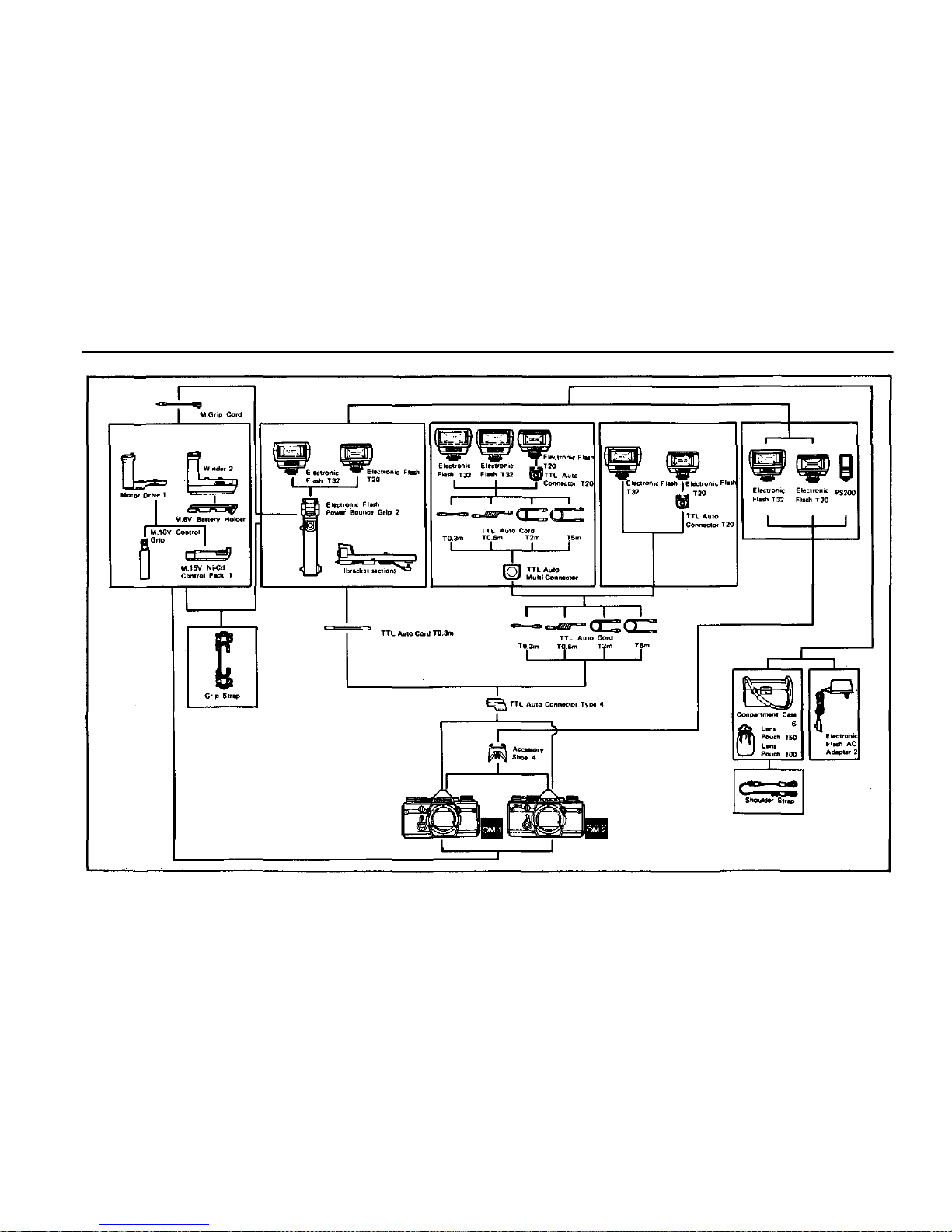
FLASH PHOTOGRAPHY SYSTEM CHART
MOTOR DRIVE
BOUNCE FLASH
MULTIUNIT
FLASH
REMOTE CONTROL
FLASH
CLIP-ON
FLASH
63
Page 65
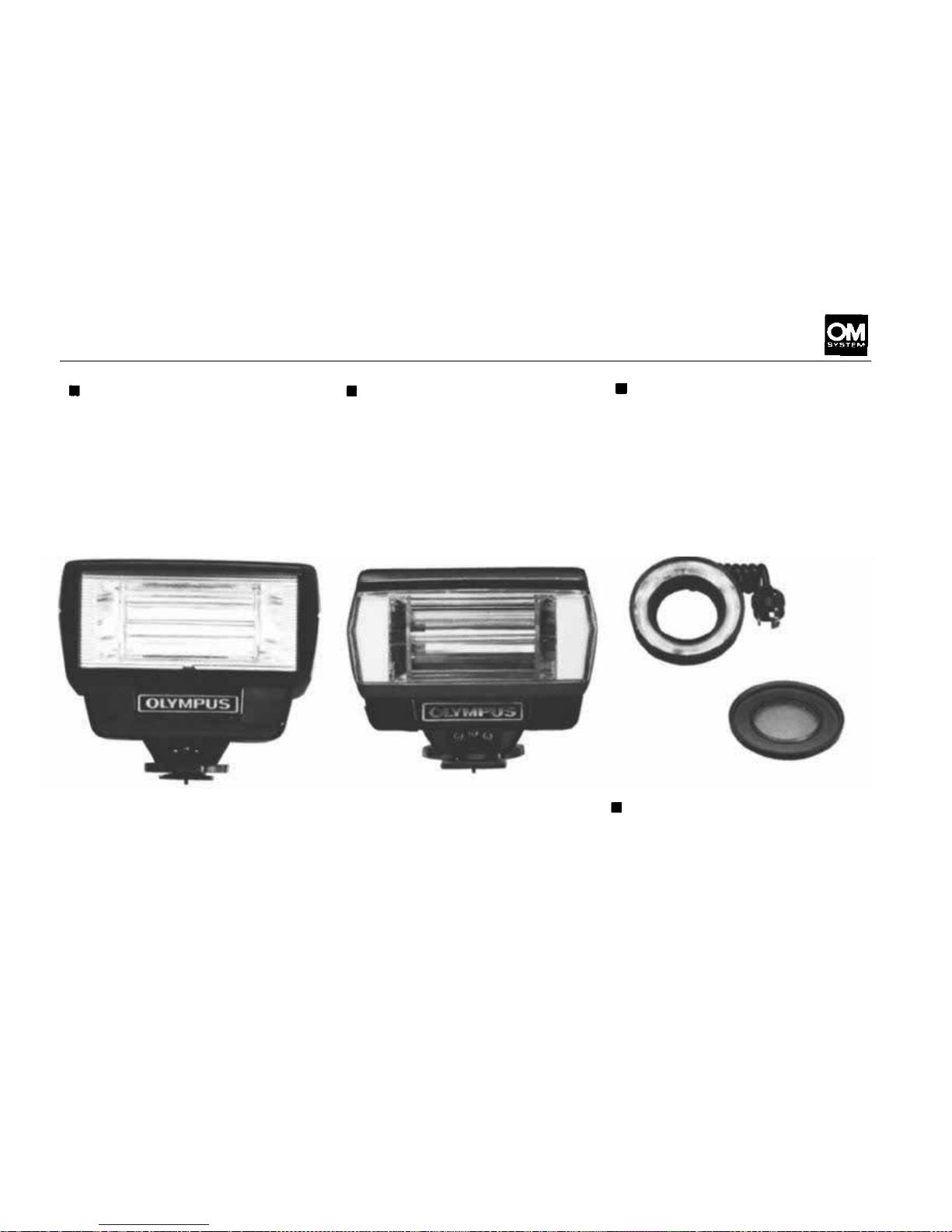
FLASH PHOTO GROUP UNITS
Electronic Flash T32
The T32 is the center of the
modular OM Flashphoto system.
Used alone on the camera, the
built-in bounce mechanism
allows the flash surface to be
tilted 90° up and 15° down. This
angle range can be further extended when the T32 is slipped
into the Power Bounce Grip 2.
Electronic Flash T20
Extremely compact and light-
weight. Like its sister unit T32,
the T20 i s a n energy-saving, fully
automatic
system
flash
unit
capa-
ble of TTL Auto, normal Auto
and manual flash and provides
the flash charge/correct exposure
indication in the OM camera
viewfinder (but with no built-
in bounce mechanism). Operates
T10 Ring Flash 1
Designed principally for use with
the OM System macro lenses, this
unit provides full and even flash
illumination at working distances
far closer than possible with
other flash units. Operates in
conjunction with the T Power
Control 1.
Operates on four 1.5V AA (selfcontained) or C batteries (inside
bounce grip) including Ni-Cd, or
AC house current. 104 x 81 x
70mm (4.1"x3.2"x 2.8"),320g.
(11.3 oz.) less batteries.
on two 1.5V AA (self-contained)
or four 1.5V C (inside bounce
grip) including Ni-Cd, or AC
house current. 77 x 68 x 57mm
(3" x 2.7" x 2.2"), 160g. (5.6
oz.) less batteries.
Ring Cross Filter POL
A cross-polarizing filter which
minimizes dir ect reflections from
the T10 Ring Flash 1 for highly
reflective subject matters.
64
Page 66
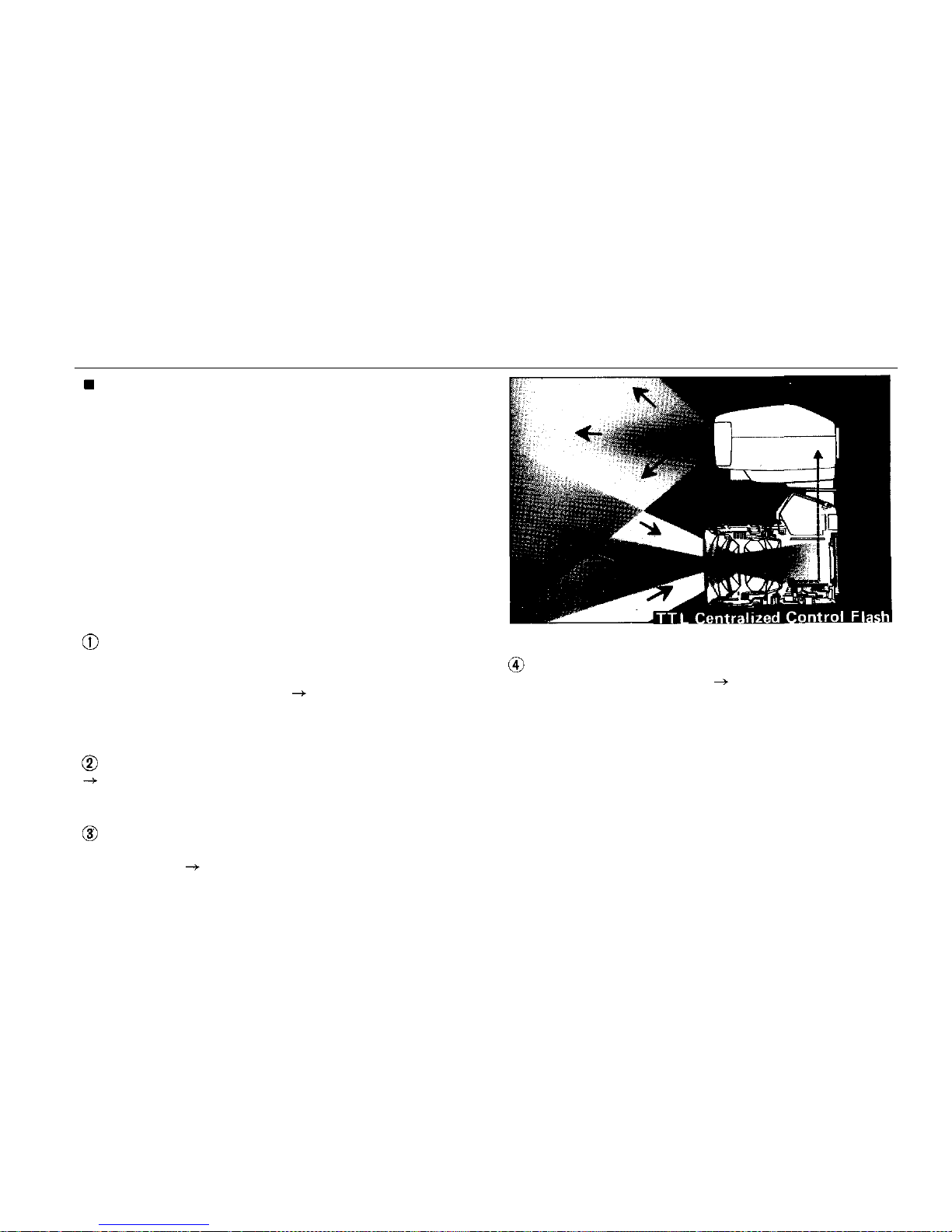
FLASH PHOTO GROUP UNITS
TTL Centralized Control Flash by T32 (T20)/
OM-2 Combination
The T32 (T20) utilizes the OM-2's own built-in
SBC light sensors. The sensors read the build-up
of
light
from
the T32
(T20)
which
passes
through
the taking lens to reach the film surface, letting
the electronic brain of the camera cut off the
flash emission when the correct exposure has been
made.
On conventional auto flash units, the auto sensor
is
built
into
the
flash
unit.
The
sensor regulates
flash emission independently of the camera. While
normal auto flash units can also give a correct ex-
posure, they are far less versatile and convenient
in use. Their drawbacks include:
The need to set film speed and lens aperture
on
both
the
camera
and the
flash
unit,
which
leads
to exposure errors caused by mistaken film speed
and/or aperture alignment. With the T32 (T20)/
OM-2 combination, once these values have been
set on the camera there is no need to reset them
on the flash unit.
Restrictions on the f-number that can be used.
With the T32 (T20)/OM-2, f-number can be
selected freely because the light is measured
through the camera lens.
Inability to change the light measuring angle
of the sensor according to the taking angle of the
chosen lens. With the T32 (T20)/OM-2, light
measuring angle always coincides with the picture
angle of the taking lens.
Restricted close-up range and incompatibility
with extension tubes, etc. With the T32 (T20)/
OM-2, close-up and diffused flash photography
can be made easily. As the exposure is calculated
inside the camera, the methods of using the flash
unit are entirely unrestricted.
65
Page 67
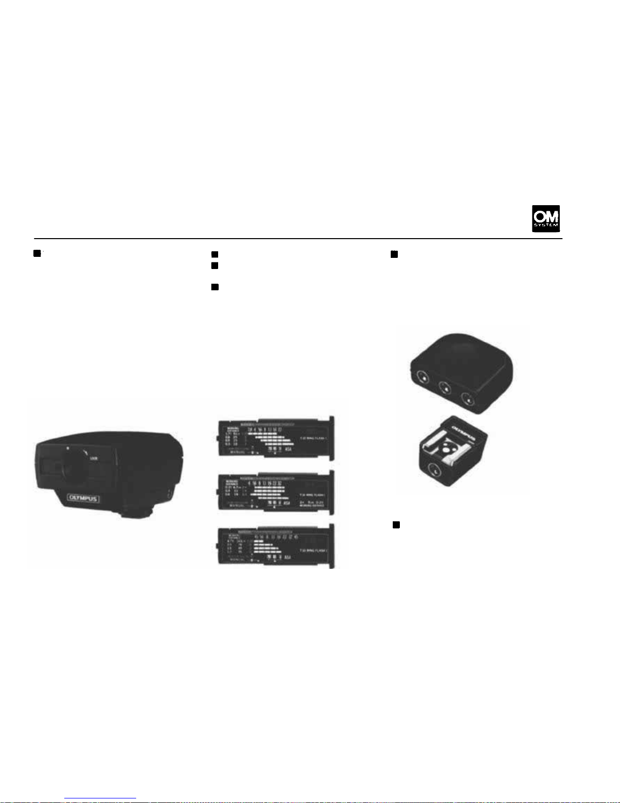
T Power Control 1
A compact power unit for the
T10 Ring Flash which mounts
via accessary shoe to the top of
the OM body. Offers TTL Direct
"OTF" auto operation or manual
flash (GN 10andGN 4, ASA 100
in meters). Powered by 4 AA size
batteries or optional AC Adapter
3.
Calculator panel for 50mm lens
Calculator Panel for 1:1
Macro 80mm lens
Calculator Panel for Macro
135mm lens
Fitted on to the back of the
T10 Power Control 1 to provide
easy-to-read distance/magnification/aperture exposure tables.
The plate for 50mm lens comes
equipped with the T10; other
two types are optionally avail-
able.
TTL Auto Multi Connector
All ow s multiple flash units (T32s
or T20s) to be combined with
the camera (OM-2N, or OM-2 in
TTL Auto; OM-1N in manual
mode) via TTL Auto Cords for
simultaneous flash photography.
TTL Aut o Connector T20
Allows the T20 to perform offcamera flash via the TTL Auto
Cord T when the Power Bounce
Grip 2 is not used (i.e., hand-held
or tripod mounted).
66
Page 68
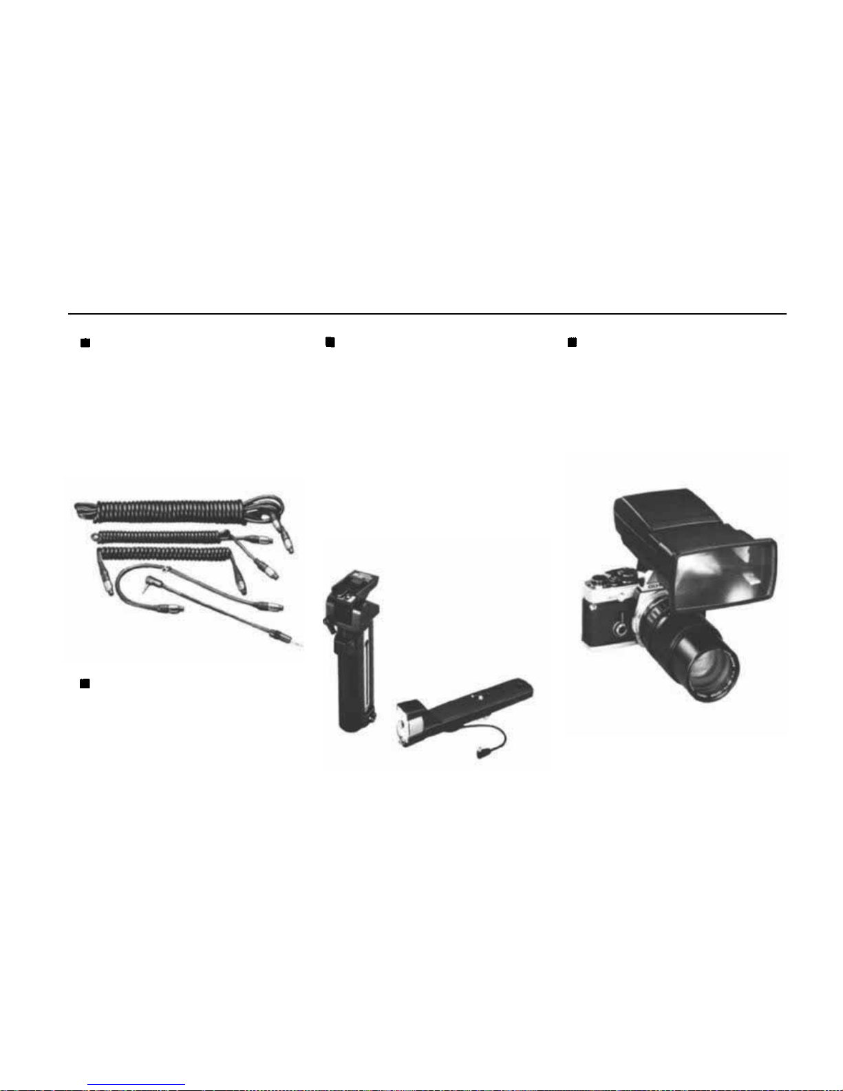
FLASH PHOTO GROUP UNITS
TTL Auto Cords T 0.3m,
0.6m,
2m, 5m
Links the T32 and T20 elec-
tronic flash units with the OM
body when used separate from
the camera. In addition to the
0.6 meter spiral cord, 0.3m, 2m
and 5m cords are available.
Power Bounce Grip 2
An auxiliary power unit which
converts the T32 and T20 elec-
tronic flash units into grip-type
units. The grip head may be
angled in all directions — 90°
up and 20° down, 240° to the
left, 60° to the right — for
maximum versatility in bounce
and close-up flash. Grip section
houses four 1.5V C size batteries.
M. Grip Cord
Connects the remote shutter release on the Power Bounce Grip
2 for operation with the Motor
Drive 1 or Winder 2 units.
Zoom Adapter T32
Offers concentrated flash beam
with the T32 Electronic Flash
sufficient for telephoto lenses
135mm and longer.
67
Page 69
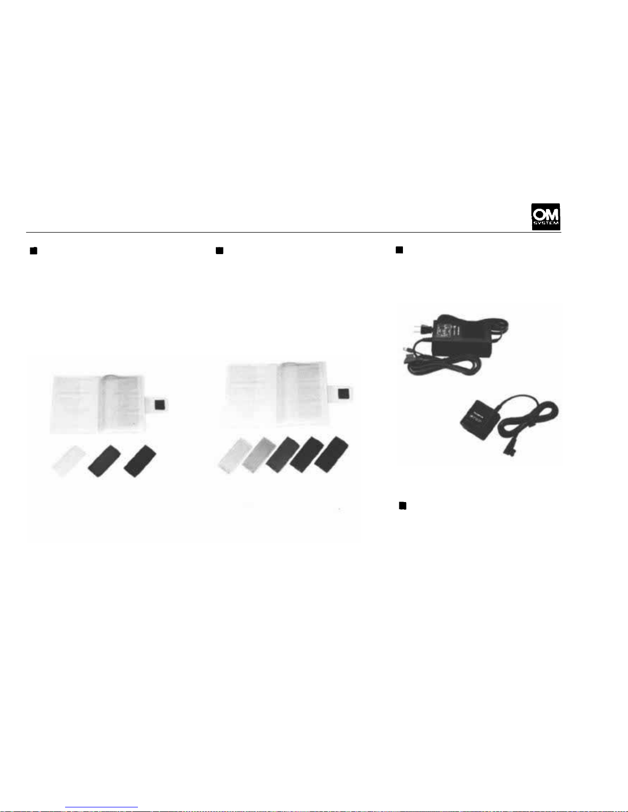
Wide Adapter-
ND Filter Set T32
Special neutral density filters
for the T32 Electronic Flash
for reducing the light intensity
without affecting color and
contrast.
Color Filter Set T32
For special effects flash.
Electronic Flash AC Adapters
Enables operation of the T10
Ring Flash 1 and its modelling
lamp on AC current.
Electronic Flash A C
Adapter 2
Plugged into an AC wall outlet,
this unit supplies a virtually un-
limited number of economical
flashes with the T32 (or T20).
68
Page 70
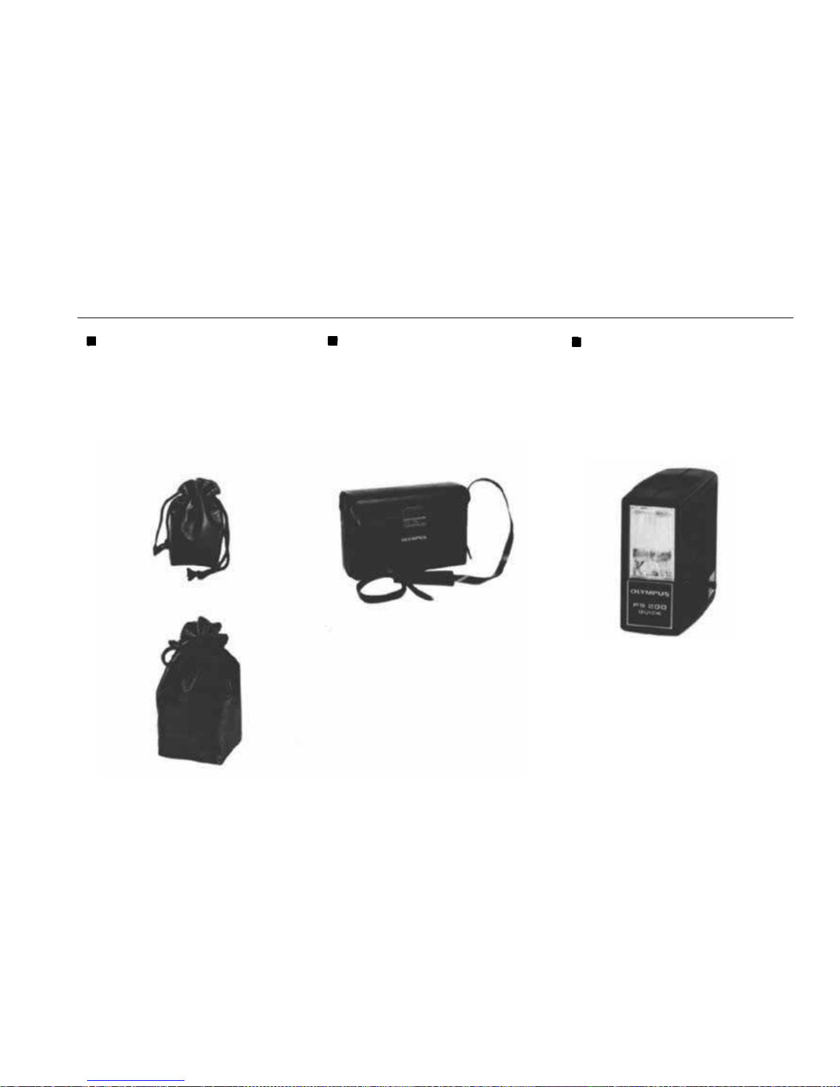
FLASH PHOTO GROUP UNITS
Lens Pouches 150/100
The Lens Pouch 150 (100) is
also suitable for carrying the T32
(T20) electronic flash unit, on
its own.
Compartment Case S
A
hard
shoulder
case
with
two
adjustable partitions to accom-
modate the OM Body, T32 (or
T20), bounce grip and bracket.
OLYMPUS PS200/PS200
Quick
These manual f las h units are for
use with cameras with a hot shoe
mount, have the guide number
of 14 (in meters) or 45 (in feet)
at ASA 100 and a constant flash
duration of 1/1000 sec. and de-
liver approx. 200 flashes. The
PS200 operates on two 1.5V
AA batteries (r ecycling time ap-
prox. 7 sec.) and the PS200
Quick on four A A batteries (2~
3 sec.). PS200: 31 x 55 x 64mm
(1.2" x 2.2" x 2.5"), 75g. (2.6
oz.) less batteries. PS200 Quick:
32 x 73 x
71mm (1.3" x 2.9"
x
2,8"),
95g. (3.4 oz.)
less
bat-
teries.
69
Page 71
Page 72
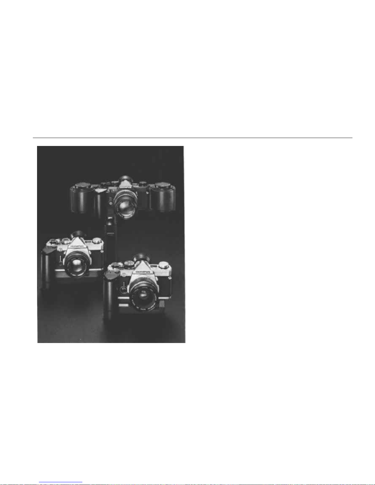
MOTOR DRIVE GROUP
The attraction of the motor drive is its ability to
capture fleeting phenomena which exceed the
capabilities of human response. Tailored perfect-
ly to match the OM camera body, each unit of
the Motor Drive Group has been reduced in size
to enhance its maneuverability and ease of operation.
The basic motor drive package (Motor Drive 1 +
M. 18V Control Grip 1,or Motor Drive 1 + M. 15V
Ni-Cd Control Pack 1) features an amazingly
compact and lightweight design, permitting handheld photography even w ith a 300mm t e l ephoto
lens, for shooting sports and news events or other
action subjects. The Winder 2 is designed for th e
ultimate compactness operating on self-contained
batteries to perform single or sequential shooting.
The 250 Film Back 1, which holds enough bulk
film to give 250 exposures, attaches to the OM
camera body without cords. The M. A C Control
Box is useful for copy work, time-lapse and other
photography by transforming household current
to DC fo r motor drive use via a relay cor d.
The many uses of the units of the Motor Drive
Group in conjunction with other units of the
Macrophoto, Photomicro and Flash Photo Groups
permit even a greater range of photographic possibilities with the motor drive than originally
imagined.
71
Page 73
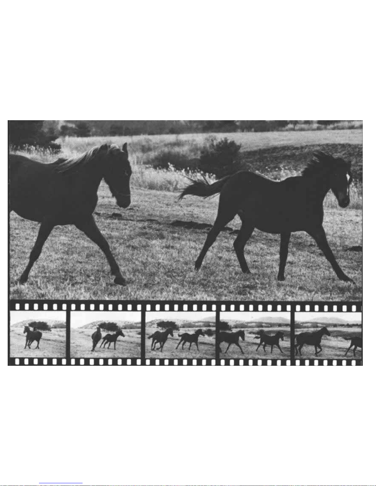
Page 74
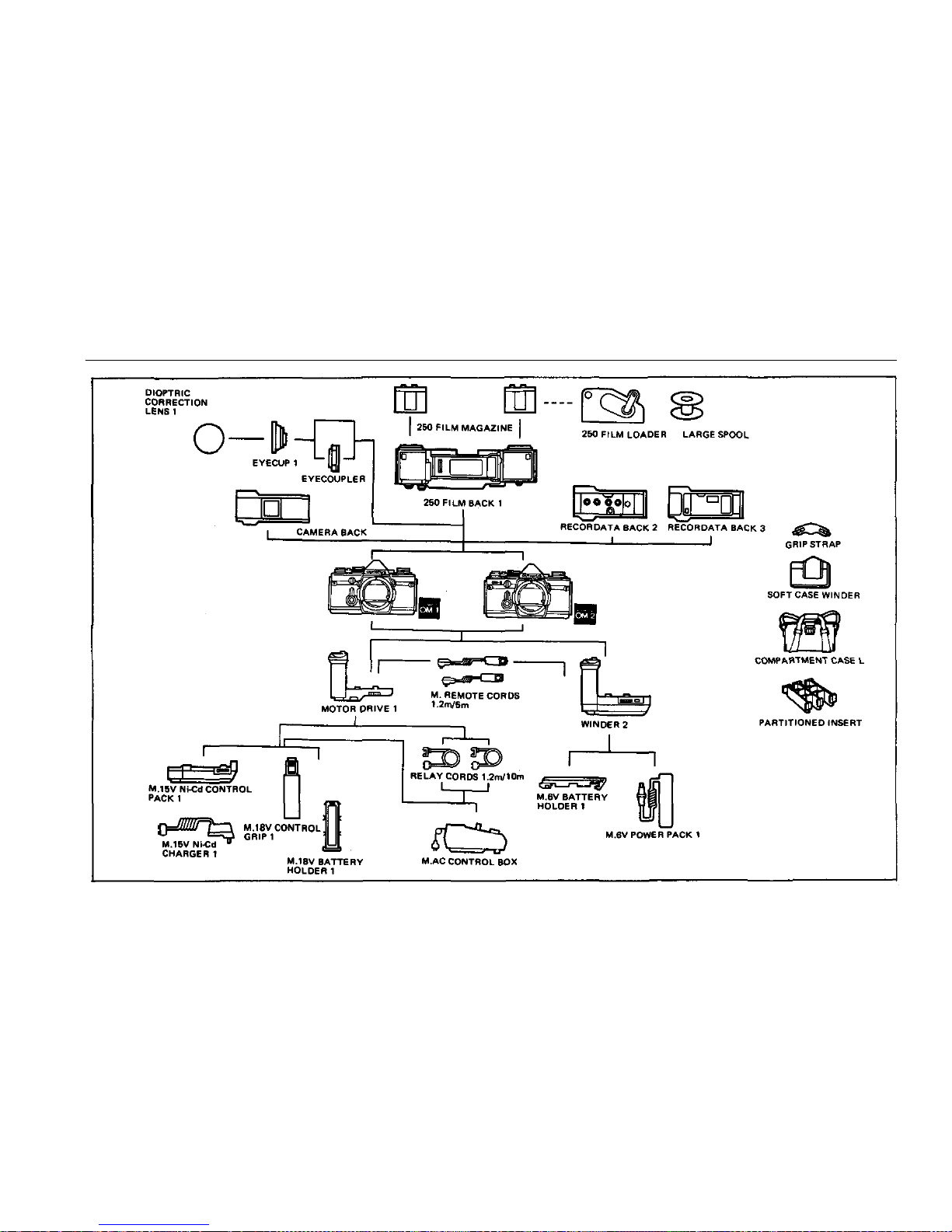
CHART OF MOTOR DRIVE GROUP
73
Page 75
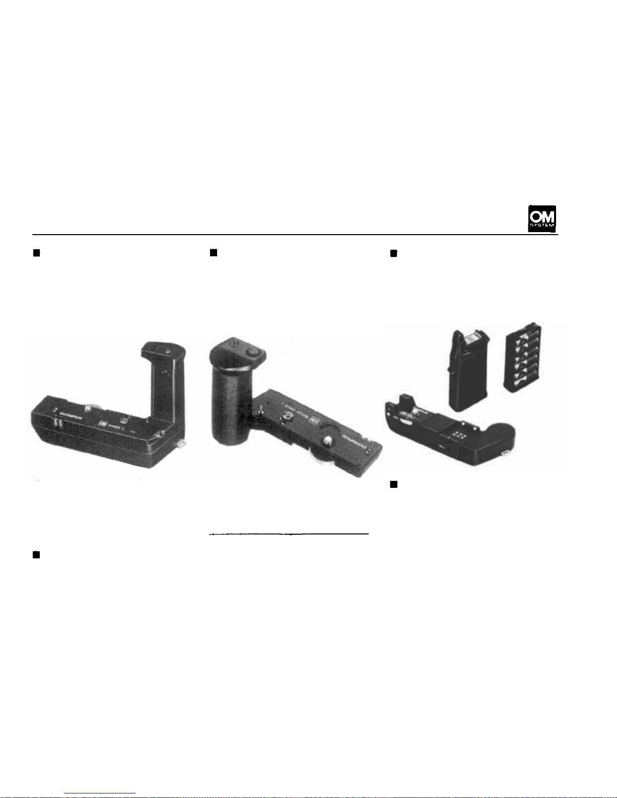
MOTOR DRIVE GROUP UNITS
Winder 2 (with M. 6V Battery
Holder 1 )
Attached directly to the camera
base, the Winder 2 performs
single frame as well as sequential
shooting (2.5 fps).
Motor Dr iv e 1
The basic motor drive unit that
forms the foundation of the
group. Attached directly to the
camera base together with the
power supply. It is capable of
single frame shooting and sequential filming of 5 frames per
second.
M.18V Control Grip 1 ( with
M. 18V Battery Holder 1)
A power supply that accepts 12
AA batteries. Can be attached
quickly to the Motor Drive 1.
Si ze: 136 X 87 X 32mm. W eight:
160g (less batteries).
Operating on 4 self-contained
AA Alkaline batteries, it is capa-
ble of powering approx. 50 rolls
of 36-exposure film.
Size: 130 X 64 X 98mm (5.12
X 2.52 X 3.86 in.). Weight:
290g (10.2 oz.) (less batteries).
M. 6V Power Pack 1
This pocketable power unit (4
AA batteries) connects to the
Size: 116 X 82 X 66mm (4.57
X 3.23 X 2.59 in.). Weight:
210g (7.4 oz.).
Winder 2 via a 1.2m cord. Warm-
ed by photographer's body heat,
permits operation in tempera-
tures as low as—10° C (14° F).
M. 15V Ni-Cd Control Pack 1
This is a flat-type rechargeable
power unit equipped with a builtin Ni-Cd battery to power the
Motor Drive 1.
Size: 129 X 35 X 67mm. Weight:
260g.
74
Page 76
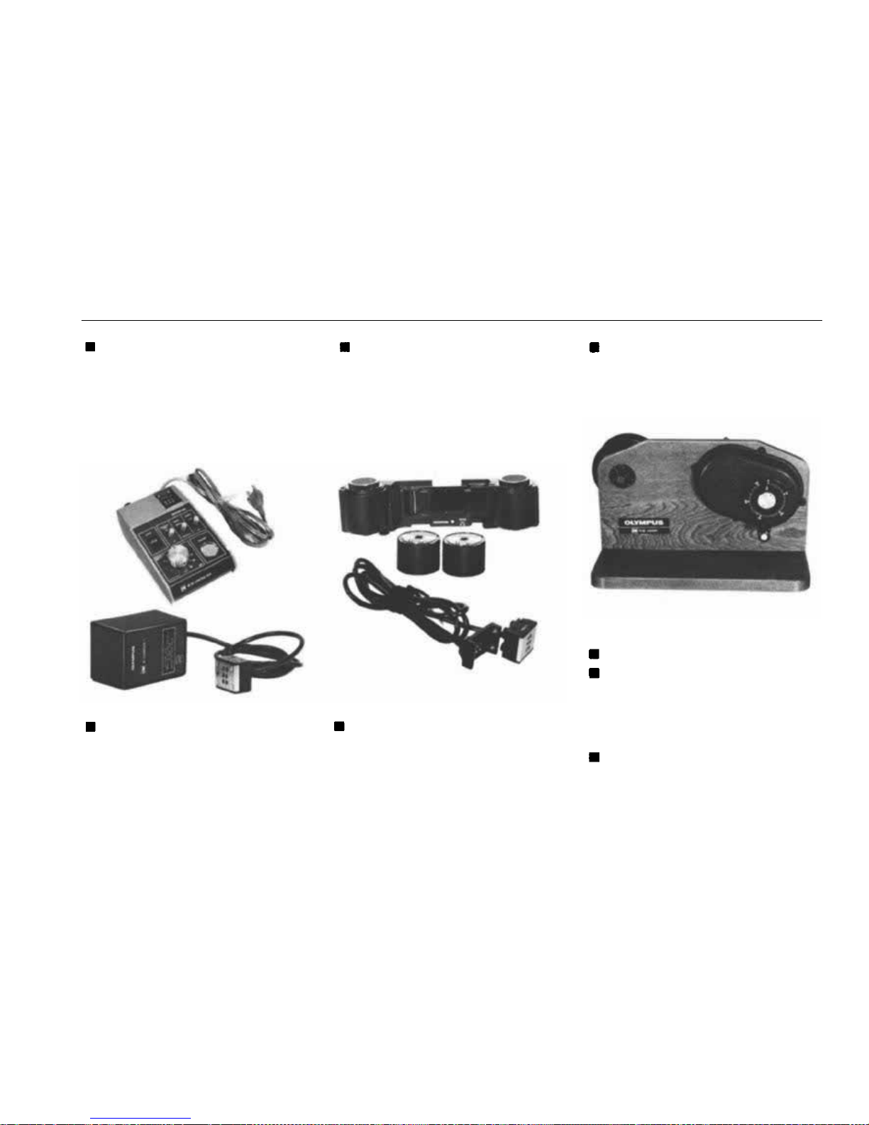
MOTOR DRIVE GROUP UNITS
M.AC Control Box
AC transformer for use with
household current. Incorporates
a sel ector swit ch between singleframe and sequential exposure
operation, a terminal for the re-
lay cord and an intervalomejer.
250 Film Back 1;250 Film
Magazine
Used with the Motor Drive 1 or
Winder 2 for roll films up to
250 exposures. Two Magazines
are necessary.
M. 15V Ni-Cd Charger 1
This AC adapter is necessary to
charge the M. 15V Ni-Cd Control
Pack 1.
Relay Cords 1.2m and 10m
Extension cords between the
Motor Drive 1 and the power
source for remote control.
250 Film Loader
Used in the darkroom for loading the 250 Film Magazine from
33m (100 ft.) bulk film rolls.
Compartment Case L
Partitioned Insert
Can be slung over the shoulder
or carried by hand. If used with
an optionally available partitioned insert, the Case L accommo-
dates motor drive equipment.
M. Remote Cords 1.2m/5m
To be fitted into the remote
control jack of the Motor Drive
1 and Winder.
75
Page 77
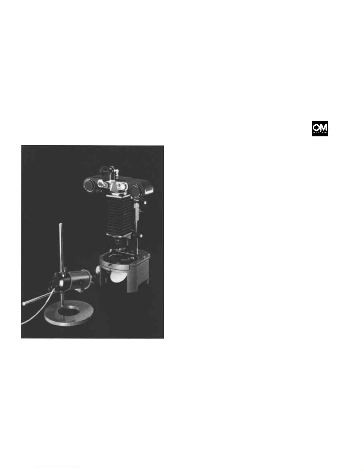
MACROPHOTOGRAPHY GROUP
Due to recent advances in macrophotography, it
has become possible to discover patterns and
colors of unsuspected beauty in the minutiae of
nature. A fast growing number of scientists and
amateurs are taking the opportunity to explore
the living world around them to new depths.
The Macrophotography Group of the OM System
provides all the tools necessary to capture this
world of perfection on film, offering a complete
range of convenient high performance accessories
designed for specialists in the various fields of
macrophotography. Starting from close-up photo-
graphy with simple accessories such as Close-up
Lenses, and Extension Tubes, you can extend
your photographic excursions into the macrophoto world with the five Macro Lenses, Auto
Bellows, Stands, Adapters, and a large variety of
lighting equipment. This Grou p has no equal in
its wide variety of accessories for macrophotography with a magnification range fro m 1/1 Ox to
about 10x, and heightens the value of the OM
System in pursuit of perfection on film.
76
Page 78
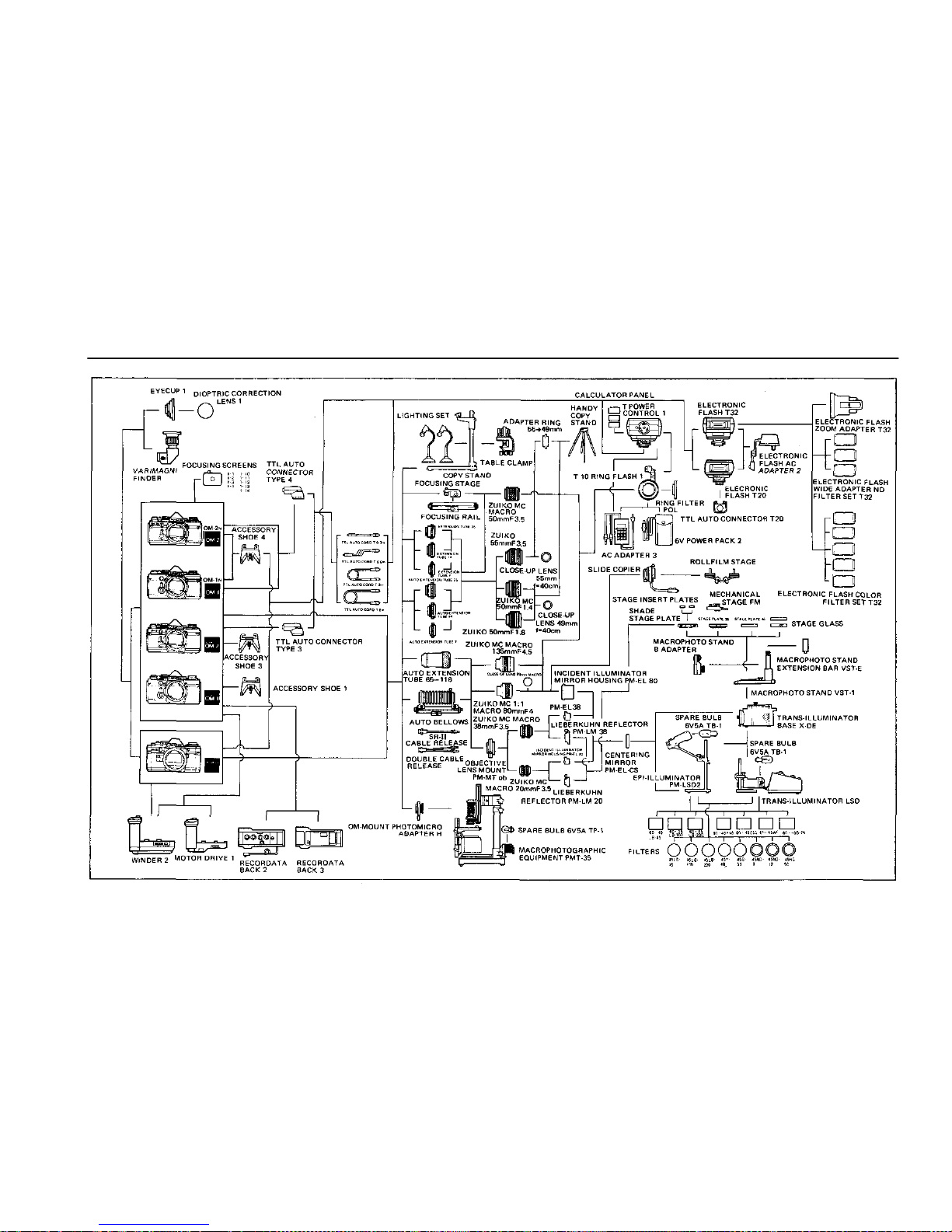
CHART OF MACROPHOTOGRAPHY GROUP
77
Page 79
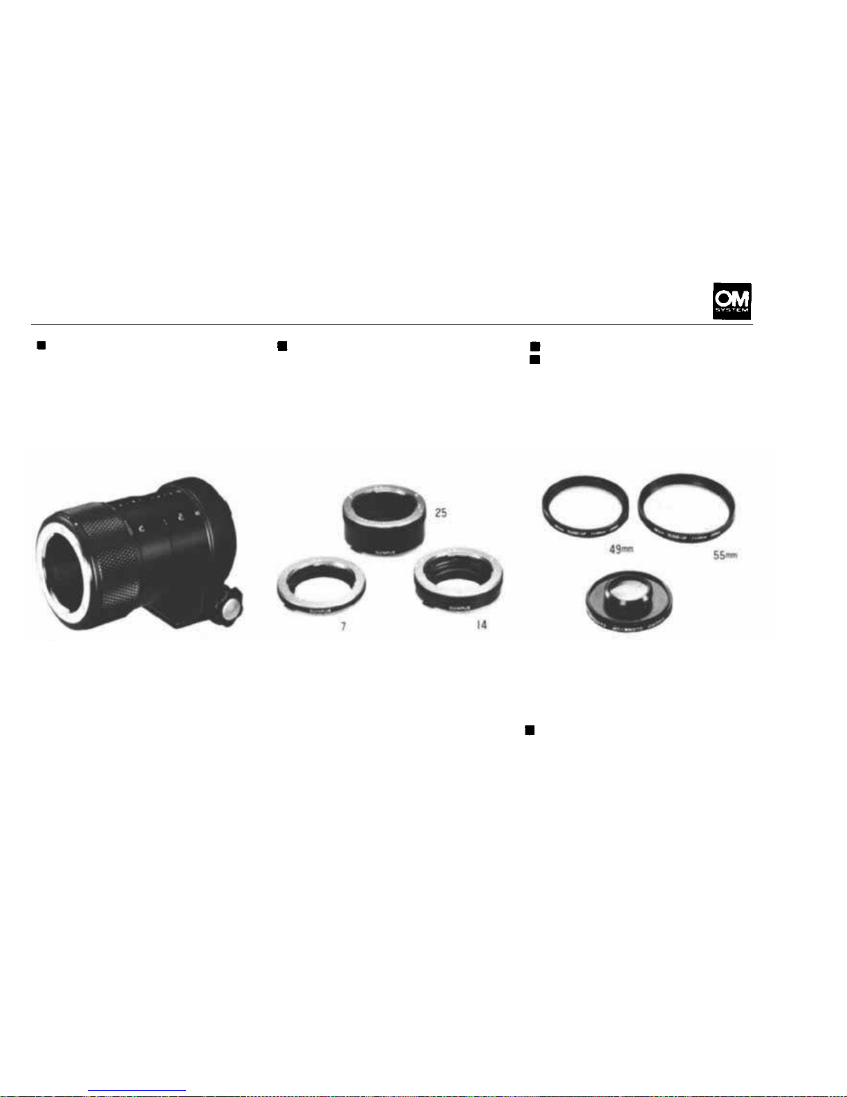
MACROPHOTOGRAPHY GROUP UNITS
Telescopic Au to Tube 65-116
Featuring automatic diaphragm
linkage and offering continuous
extension from 65mm—116mm,
it allows you to vary magnifications and subject area freely
making macrophoto work as
easy as snapshots. Subject area
Auto Extension Tubes 7, 14
and 25
Each of these bayonet mount
tubes fits between the OM Body
and the lens, feat urin g automatic
diaphragm linkage. Available in
extensions of 7mm, 14mm and
25mm, and can be used in 7
Close-up Lens 49mm f=40cm
Close-up Lens 55mm f=40cm
These attachment lenses thread
directly over the standard lenses
or 50mm macro lens, permitting magnification increase with-
out affecting automatic dia-
phragm action. The close-up lens
extends to 72mm x 48mm (2.8"
x 1.9") when used in conjunction with the 135mm macro
lens, and runs all the way from
72mm x 48mm (2.8" x 1.9")
to 36mm x 24mm (1.4" x 0.9")
in conjunction with the 1 : 1
Macro 80mm lens.
different combinations in total
to give a variety of magnifica-
tions. Another set of these
extension tubes of the sam sizes
without the automatic dia-
phragm linkage is also available.
For magnifications 0.5x and
higher however, the 50mm
macro tenses are recommended
for superior resolution.
49mm is used with the 50mm
F1.8 and F1.4 standard and
50mm macro lenses; the closeup lens 55mm with the 55mm
F1.2 standard lens.
Close-up Lens 80mm Macro
For use with th e M C 1 : 1 Macro
80mm lens to extend magnifica-
tions with the Telescopic Auto
Tube from 1x to 2 x .
78
Page 80
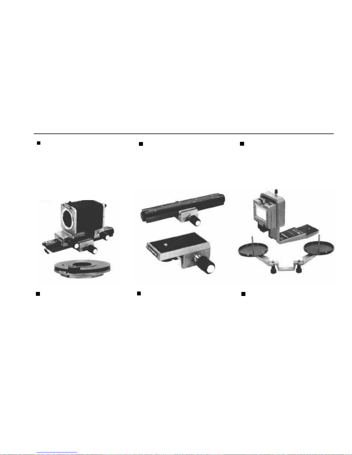
Auto Bellows
A
basic
unit
extending
your
close-up and macrophotographic
capabilities. Provided with the
preset aperture diaphragm lever
to stop down the lens opening
of various OM lenses at the mo-
ment of exposure in conjunc-
tion with the double cable release.
Focusing Rai l
This is used with the Focusing
Stage and connects to a tripod,
the Copy Stand, or Macrophoto
Stand B Adapter, so that the
camera can be smoothly moved
along the Rail, allowing you to
focus and compose as desired.
Slide Copier
For use in conjunction with the
Auto Bellows to produce duplicates from frame-mounted slides
or strip slides. The 1:1 Macro 80
mm is recommended for best re-
sult with the Slide Copier.
Objective Lens Mount PM-
MTob
This objective mount enables
you to mount the Zuiko Macro
20mm and 38mm to the Auto
Bellows.
Focusing Stage
Allows you to mount the cam-
era body on the Focusing Rail
or Auto Bellows. When used with
the Rail, you can change the
camera position for fast and
smooth focusing and composing.
Roll Film Stage
Attached to the Slide Copier to
hold long roll films for duplication.
79
Page 81
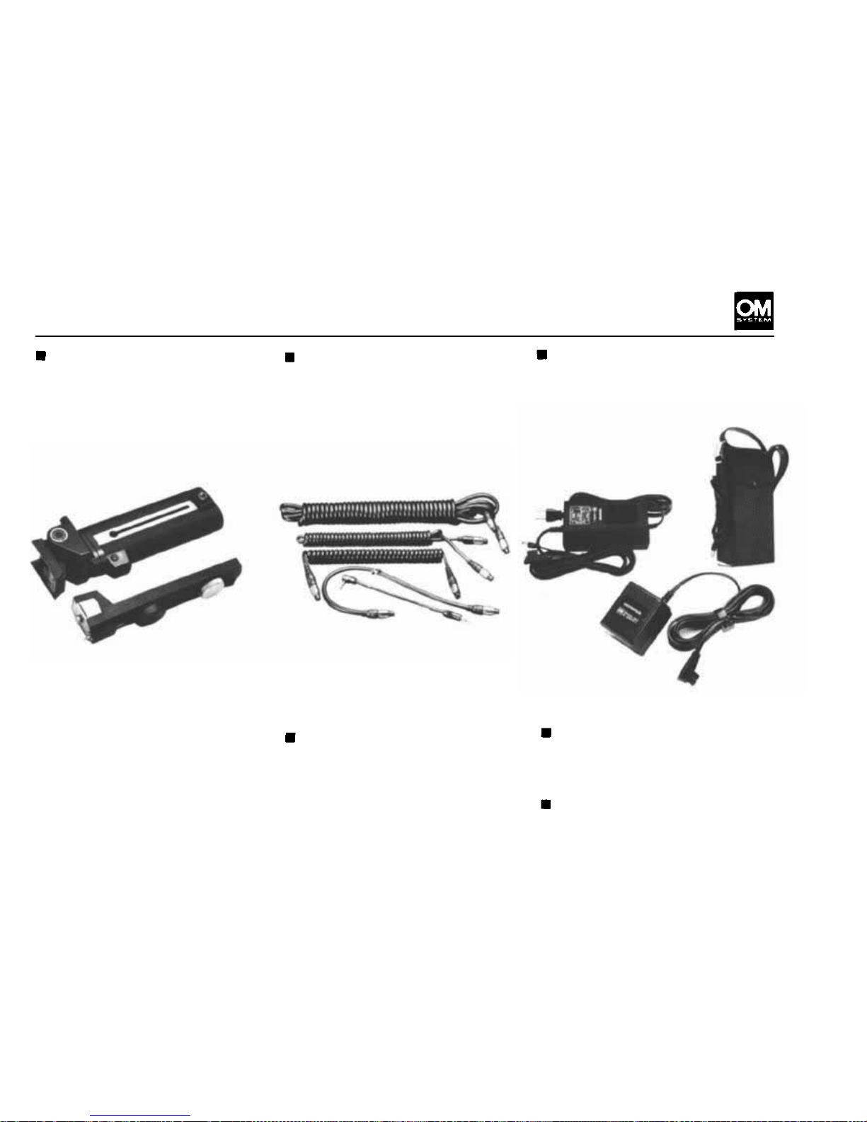
Power Bounce Grip 2
Converts the T32 (or T20) into
a
grip
type
electronic
flash
unit.
Consists of a bracket section and
a grip section which contains
4 C batteries to provide a powerful supplementary power source.
The bounce head can be angled
90° up, 20° down, 60° right and
240° left allowing free choice of
bounce and close-up flash photography. Electrical connection
with the camera is made via the
TT L Au to Cord T and TTL Aut o
Connector.
TTL Auto Cord T 0.3m, 0.6m,
2m, 5m
Used for off-camera flash operation (e.g., bounce flash, multiunit flash). Available in 4 dif-
fer ent lengths.
Electronic Flash A C Adapters
Enables operation of the T10
Ring Flash 1 and its modelling
lamp on AC current.
M. Grip Cord
Connects the Motor Drive 1 (or
Winder) with the shutter release
incorporated in the bounce grip
for comfortable motor-driven
flash photography.
6V Power Pack 2
An
auxiliary
power
source
unit
for the modelling lamp of the
T10 Ring Flash or winder units.
Powered by four D size batteries.
Electronic Flash AC Adapt er 2
80
Page 82
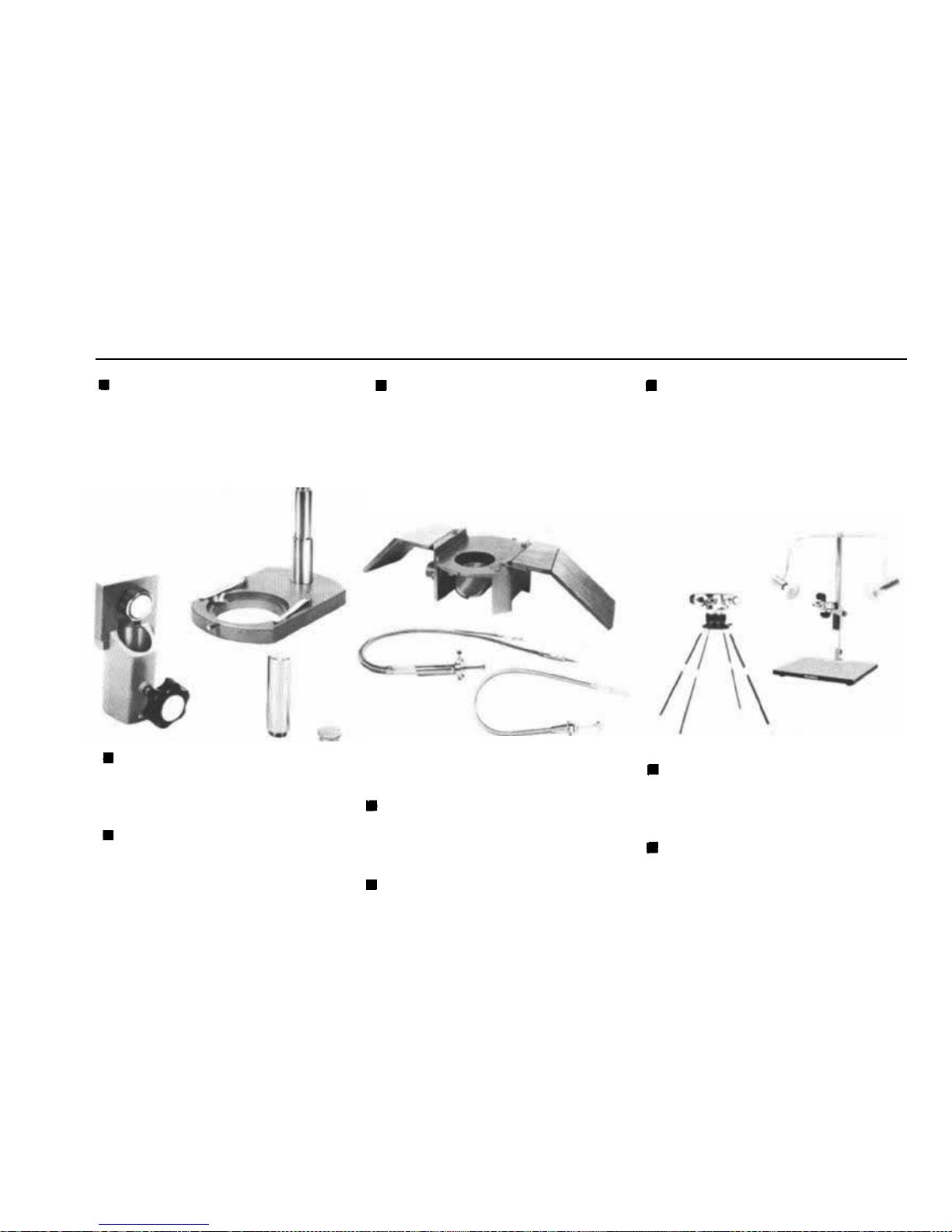
MACROPHOTOGRAPHY GROUP UNITS
Macrophoto Stand VST-1
A rugged stand specially design-
ed for close-up and high magnification photography. Usable
with
various
stage
plates.
Com-
plete with a round frosted plate
(black at back) for incident light,
and a pair of stage clips.
Trans-llluminator Base X-DE
Indispensable for holding the
Macrophoto Stand VST-1 for
magnified photographs. Supplied with a built-in 100V 20W
illuminator with a mirror, and a
pair of wooden handrests for ease
of operation. Can be used with
various stage plates and filters.
Macrophoto Stand B Adapter
For use with the Macrophoto
Stand, to support the Auto Bellows or Focusing Rail on the
Stand.
Macrophoto Stand Extension
Bar VST-E
Extends the height of the Macrophoto Stand. Length: 7.5cm
(2.95").
When used with the Lieberkuhn
Reflector, it is convenient to replace the reflector mirror with
the Centering Mirror PM-ELCS.
Double Cable Release
Attached to the Auto Bellows
and camera shutter release but-
ton, to activate them simultaneously.
Cable Release SR-11
Copy Stand
A standard type stand, 48 x 44
cm, for general close-up and copy
photography. Two additional
lights can be attached to the top
of the 80cm high stanchion. Fine
adjustment f or the camera height
and a locking device are provided.
Handy Copy Stand
A four-legged stand for close-up
and copy photography. The leg
length is adjustable to three po-
sitions.
Lighting Set
Complete with two units, each
consisting of a base and light
arm. Max. intensity: 500W.
81
Page 83
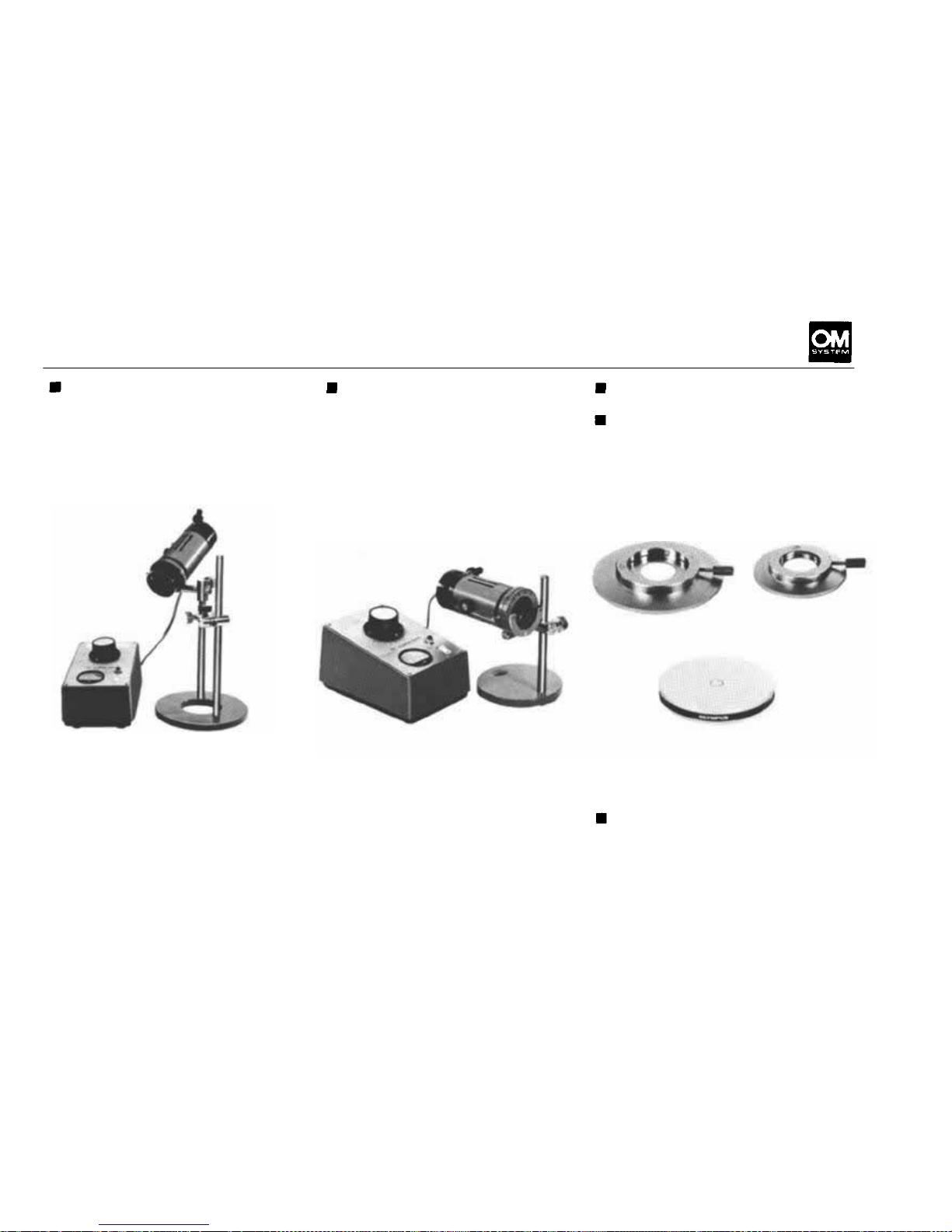
Epi-llluminators PM-LSD 2
This pair of illuminators offers
vertical illumination essential to
macrophotography. The height
of the illuminator is adjustable
on the tall pillar, suitable to over-
stage or substage illumination.
When used with the Trans-illumi-
nator Base X-DE, the Illuminator
supplies transmitted light. Focus-
ing is adjustable by shifting the
bulb filament. A 6V to 8V variable transformer is provided.
Eight filters are available in various sizes, including color, black
and white, neutral density, etc.
for transparent or translucent
subjects.
Trans-llluminator LSD
This
unit
is a
universal
type
trans-
illuminator for use with the XDE Trans-llluminator Base. When
the Lieberkuhn Reflector is added, vertical light is also available.
A 6V, 3 0 W bulb is built-in. The
condenser travels 18mm by rack
and pinion for converging, diverging and parallel adjustments
Lieberkuhn Reflector PM-
LM38
Lieberkuhn Reflector PM-
LM20
These reflectors are available for
use with the 20mm and 38mm
Macro Lenses. When used with
the LSD Trans-llluminator, they
make it possible to take photographs with excellent penetra-
of light. Complete with trans-
former and square filter 60 x
45C. Provided with a filter hold-
er for attachment of various
OLYMPUS filters, round and
square.
tion and lack of shadows.
Centering Mirror PM-ELCS
For use with these PM-EL units
for accurate centration or for
use with the Trans-llluminator
Base X-DE.
82
Page 84
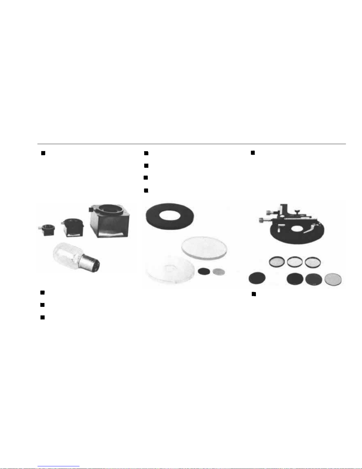
MACROPHOTOGRAPHY GROUP UNITS
Incident Illuminator Mirror
Housings PM-EL80, PMEL38and PM-EL20
These units are used with
OLYMPUS Macro Lenses in co n-
junction with the Epi-lllumina-
tor PM-LSD2 or Macrophoto-
graphic Equipment PMT-35 to
illuminate macrophotographic
objects with incident light. They
are effective when shadowless
pictures are desired.
Spare Bulb 6V 5A TB-1
(for PM-LSD2 & LSD)
Spare Bulb 6V 5A TP-1
(for PMT-35)
Adapter PM-EA
Accepts th e photosensitive probe
of the EMM-7 Exposure Meter in
conjunction with the PMT-35 or
Auto Bellows.
Stage Glasses (Clear, frosted &
black)
Stage Plate 45 (metal disc,
black)
Stage Plate 28 (metal disc,
black)
Glass Shade Stage Plate
Supplied with two stage inserts;
compatible with the Lieberkuhn
Reflector. The center port ac-
cepts the stage insert on which
a subject is placed.
Mechanical Stage FM
This stage is used to mount sub-
jects on the 28mm stage plate.
The subject travels vertically and
horizontally by precise adjust-
ments with a vernier.
Filters
Round filters are used with the
PM-LSD2 and LS D , while square
filters used with the LSD only.
They are available for color tem-
perature compensation, mono-
chromatic, neutral density, diffu-
sion, heat absorbing and inter-
ference filtration.
83
Page 85
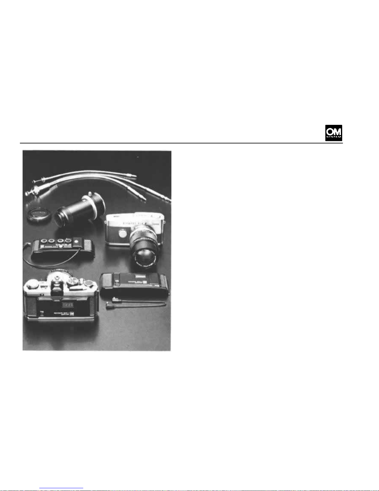
PHOTOTECHNICAL GROUP
As a leading manufacturer of optical instruments
in various fields of modern life, OLYMPUS provided the OM System with a wide variety of Phototechnical units, many of which can be used to
successfully document your valuable achievements
in photographs. This group includes a microscope
adapter for use with an operation microscope, an
astroscope adapter to explore the mysteries of
space and stars in conjunction with a telescope,
etc., mostly capable of attaching on the OM body.
Other outstanding advantages of this group are
the Recordata Backs 3 and 2 that are interchangeable wit h the OM standard camera back. Once in
place, the No. 3 Back automatically records the
date (year-month-day) or the time (day-hour-
minute) in the lower right hand section of your
picture (camera held in the horizontal position)
simultaneously with the shutter release.
Externally, data can be displayed on the liquid
crystal panel. Meanwhile, the No. 2 Back imprints
numerical and alphabetical symbols in 4-dial
coding on the picture when the exposure is made,
of great convenience in documentation, information filing, instant picture classification, etc. Both
Backs can be used for high speed motor drive photography and flash photography.
For Olympus Pen F and FT enthusiasts, a mount
adapter is also available for connection of these
cameras to the OM System interchangeable lenses
and other unit
84
Page 86
Page 87
Page 88
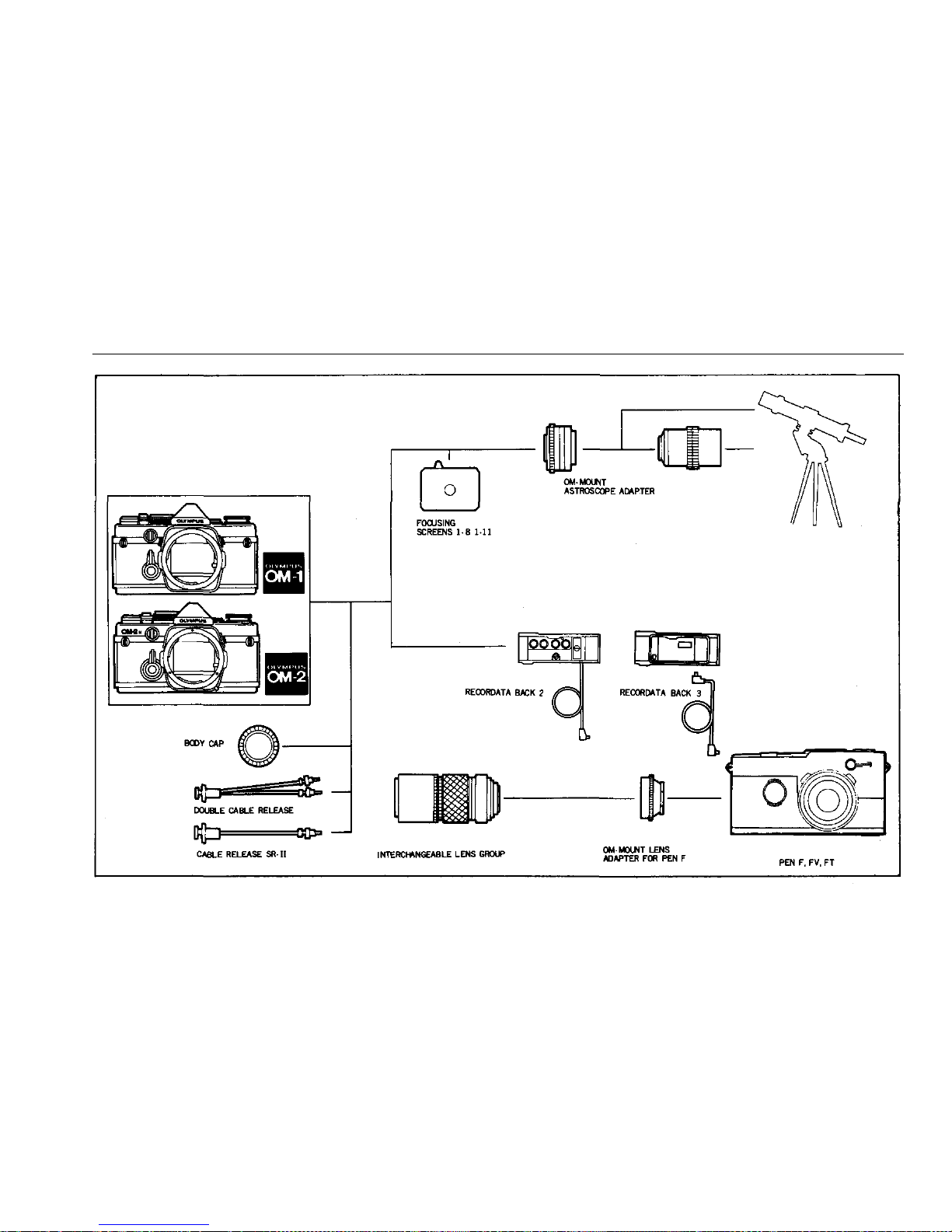
CHART OF PHOTOTECHNICAL GROUP
87
Page 89
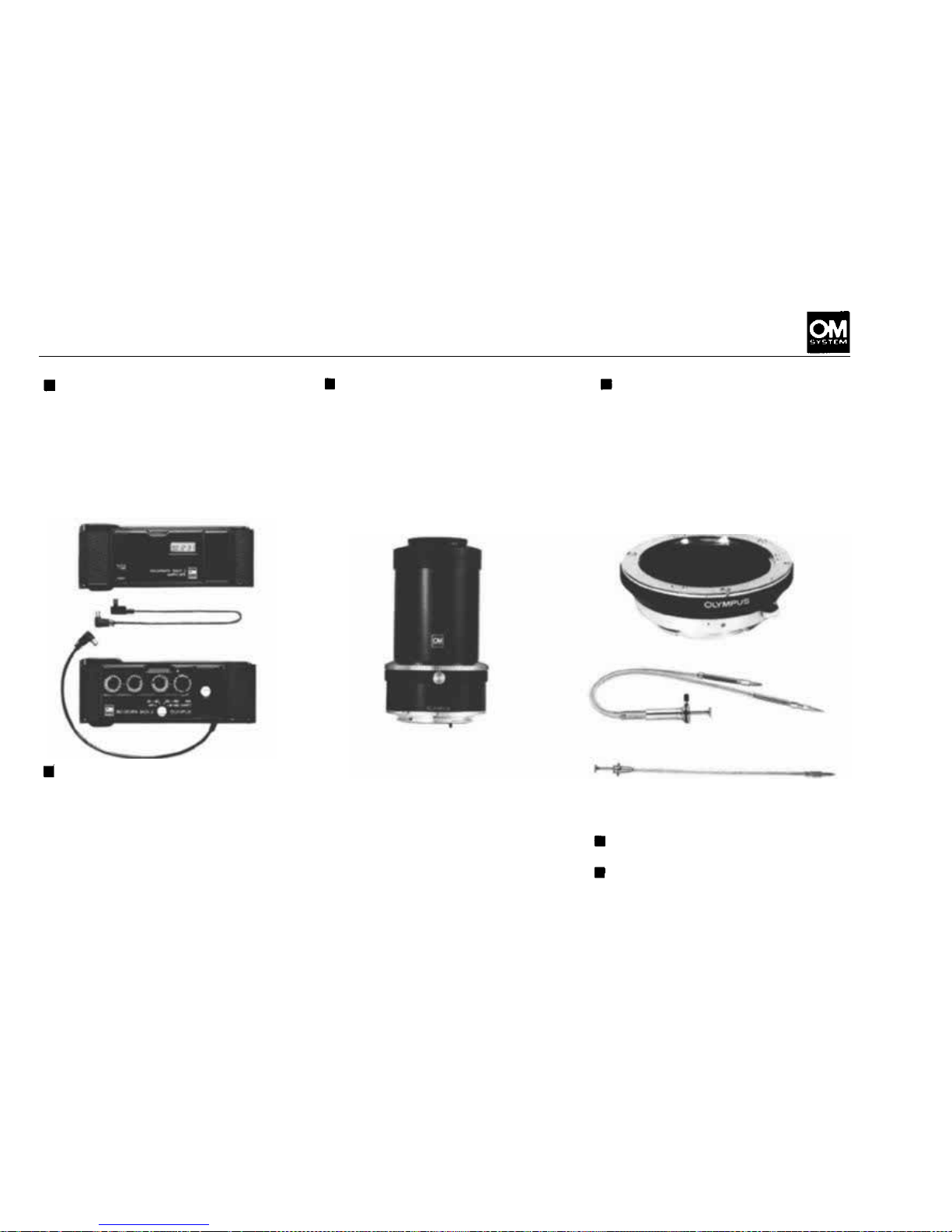
PHOTOTECHNICAL GROUP UNITS
Recordata Back 3
This
unit
replaces
the
standard
camera back to automatically
record the date (year-month-
day) or the time (day-hour-mi-
nute) on the film simultaneous-
ly with the exposure, or blank
as desired. Data display on the
liquid crystal panel.
Recordata Back 2
The Back fits on the OM body
and imprints data in the lower
right corner of the picture. The
data comprises numerical and al-
phabetical symbols for year,
month, day or other information
in 4 dial coding. C an be used for
OM-Mount Astroscope
Adapter
Permits astrophotography by
the OM Body attached to telescope by means of the 36.5mm
diam., pitch 1mm and pitch
0.75mm threads. It enables direct objective photography and
high magnification photography
through the telescope eyepiece.
highspeed sequence photography
with the Motor Drive or Winder
units, and flash photography.
Imprinting can be prevented, if
required, by simply setting the
selector switch OFF.
OM-Mount Lens Adapter
for Pen F
Connects the OLYMPUS PEN
F, FT and FV cameras to the
OM System Interchangeable
Lenses and other units.
Double Cable Release
Used with the Auto Bellows.
Cable Release SR-11
88
Page 90
PHOTOMICROGRAPHY GROUP
When the photographic magnification desired ex ceeds 10x, it becomes more difficult for the macrophotographic equipment alone to obtain excellent
pictures. A sophisticated array of photomicrography accessories with a microscope as the central figure is required. The exciting vision of look-
in g at the microscopic world through a microscope
can be recorded by the OM-2.
OLYMPUS has an outstanding reputation for
manufacturing precision microscopes used by
scientists throughout the world. Naturally, the
OM System includes a variety of microscope
adapters, rugged stands, a special shutter to prevent vibration at high magnification, and an automatic exposure mechanism which solves the difficult problem of microscope exposures.
The Photomicrography Group is designed to ex pand the photomicrographic world not only into
the scientific realm, but also into the creative
sphere, so that the photographer's achievements
under the microscope can be easily and accurately
recorded with his OM-2.
89
Page 91
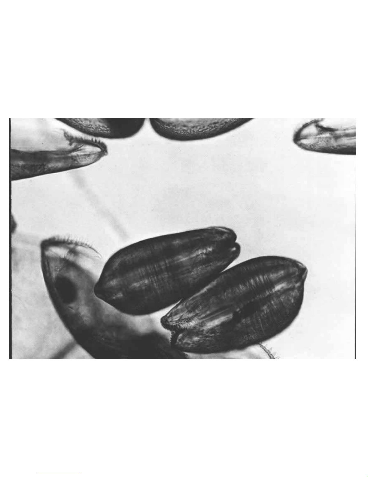
Page 92
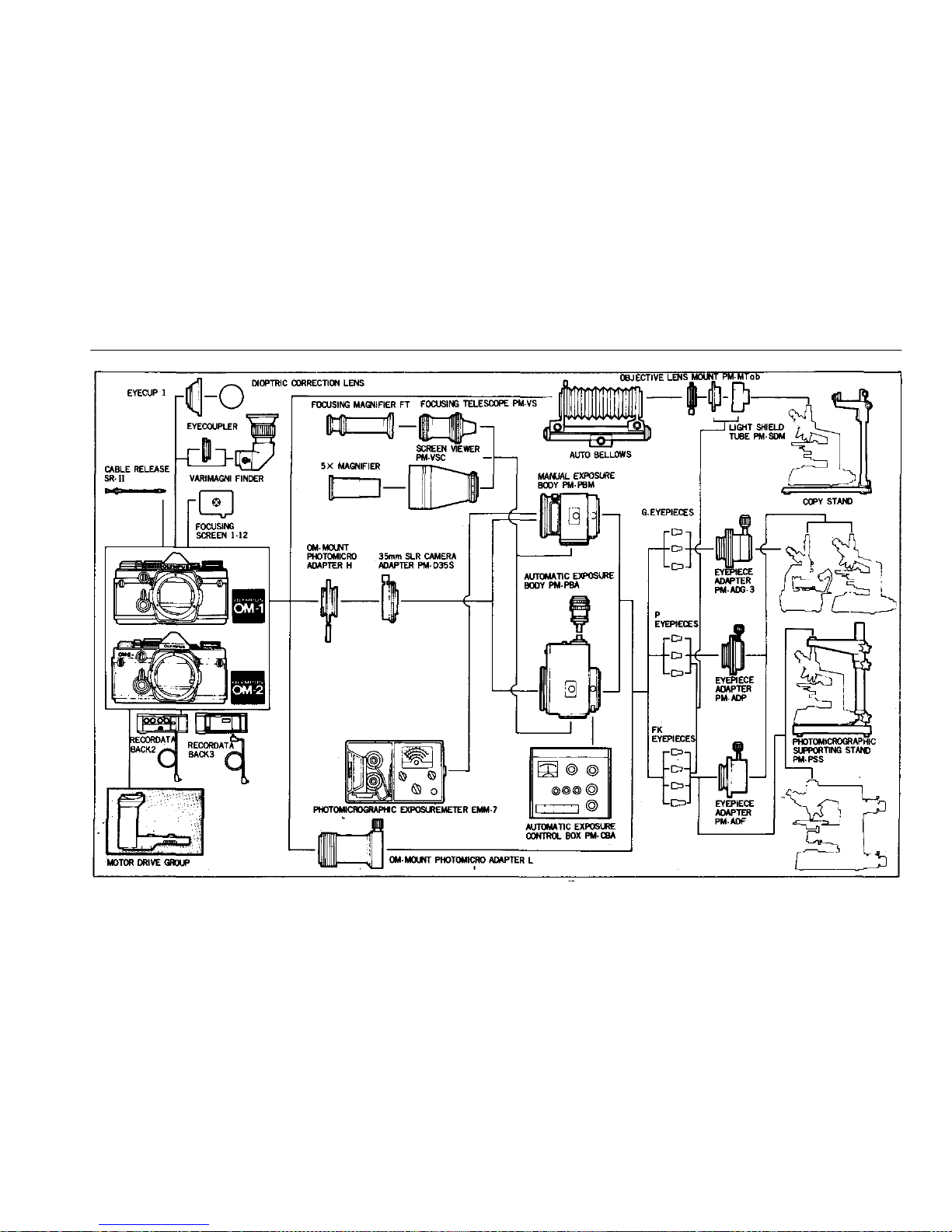
CHART OF PHOTOMICROGRAPHY GROUP
91
Page 93
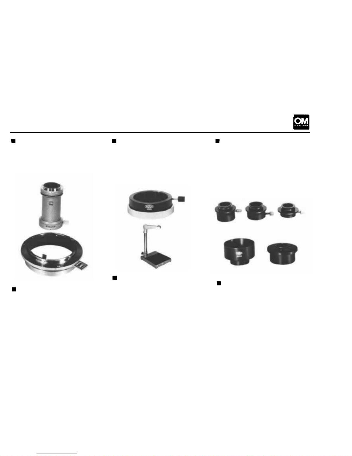
PHOTOMICROGRAPHY GROUP UNITS
OM-Mount Photomicro
Adapter L
Connects the OM Body to the
microscope for low power mag-
nification.
OM-Mount Photomicro
Adapter H
Connects the OM Body to the
Photomicrographic System PM10, automatic or manual, or
Macrophotographic Unit PMT-
35 for high power magnification.
35mm SLR Camera Adapter
PM-D35S
Used with OM-Mount Photo-
micro Adapter H to attach the
OM Body to the PM-PBA or PM-
PBM (see page 93).
Photomicrographic Support-
ing Stand PM-PSS
This
unit
is a
massive
stand
to
virtually end the major cause of
lost photomicrographs at high
magnification due to vibration.
Supports the entire camera
weight, isolating it from the
microscope.
Eyepiece Adapter PM-AOG-3,
PM-ADP, PM-ADF
Used to connect a microscope to
the OM-Mount Photomicro
Adapter L. Each Adapter designates OLYMPUS microscope
eyepieces, as follows; PM-ADG-
3 for G eyepieces, PM-ADP for
P eyepieces and PM-ADF for FK
photo eyepieces.
Light Shield Tu be PM-SDM
Designed for use with the Auto
Bellows and Objective Lens
Mount PM-MTob. Assures ex-
cellent images when used with
FK photo eyepieces at the bel-
lows length of 111mm (4.4"),
free of shutter vibra tion.
92
Page 94
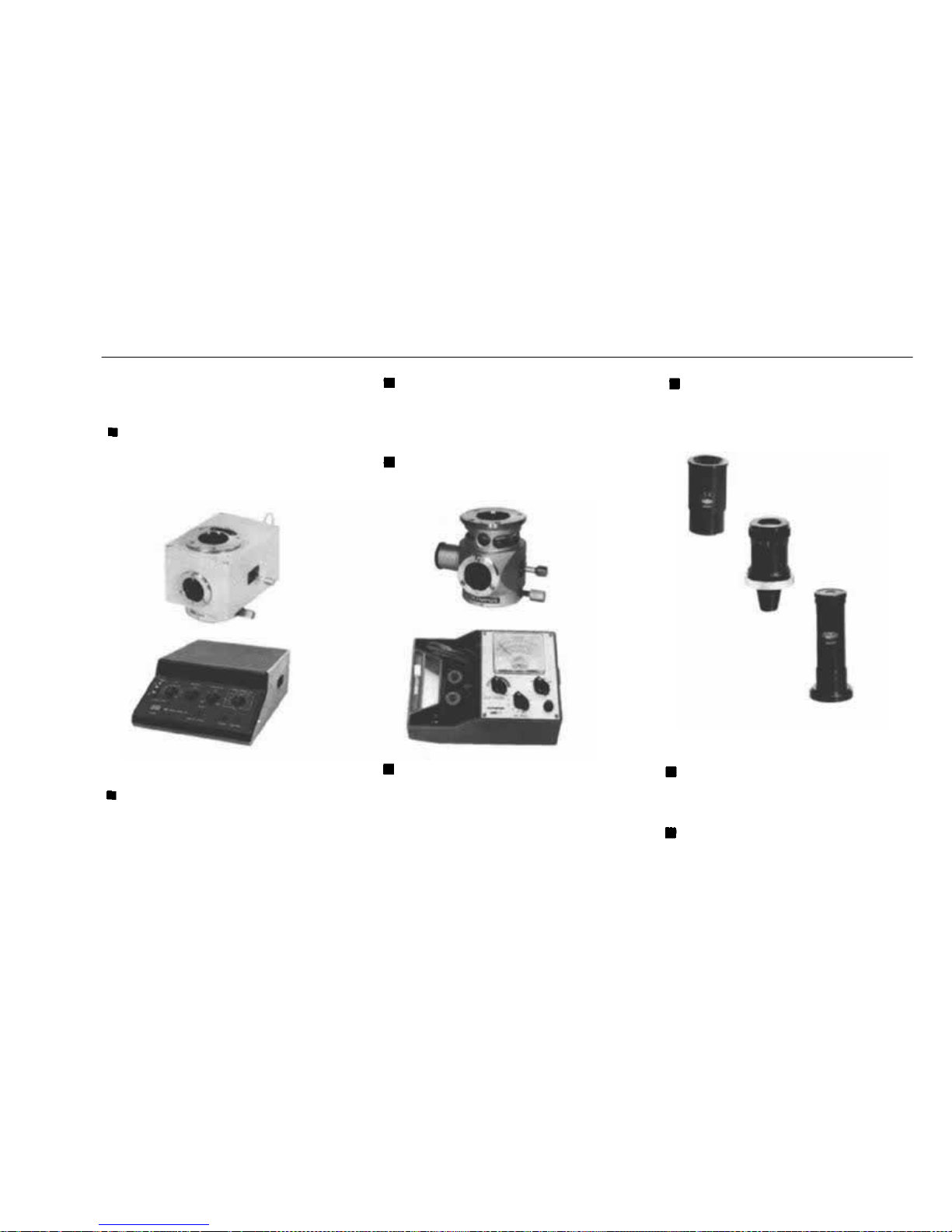
PHOTOMICROGRAPHY GROUP UNITS
System PM-10-AD
Consists of 17 units, including
the PM-PBS, PM-CBAD, etc.
Automatic Exposure Body
PM-PBS
Automatically determines accurate exposure time.
Automatic Exposure Control
Box PM-CBAD
Used with the Automatic Exposure Body PM-PBS, to regulate
color temperatures control, reciprocity failure, etc.
Manual Photomicrographic
System PM-10-M
This is a popular manual version
of the PM-10, consisting of 8
units.
Manual Exposure Body
PM-PBM
Photomicrographic Exposure
Meter EMM-7
The EMM-7 assures accurate con-
trol of both exposure and color
temperature in photomicrography. Provided with exposure
and color temperature probes,
and color-compensating filters.
5X Magnifier
For use with the Screen Viewer
for magnifying any part of the
subject area and focusing accurately.
Focusing Telescope PM- VS
For use with objectives 4x and
up in conjunction with the Automatic or Manual Exposure Body.
Focusing Magnifier F T
Used to magnify the image obtained by the Focusing Telescope.
93
Page 95
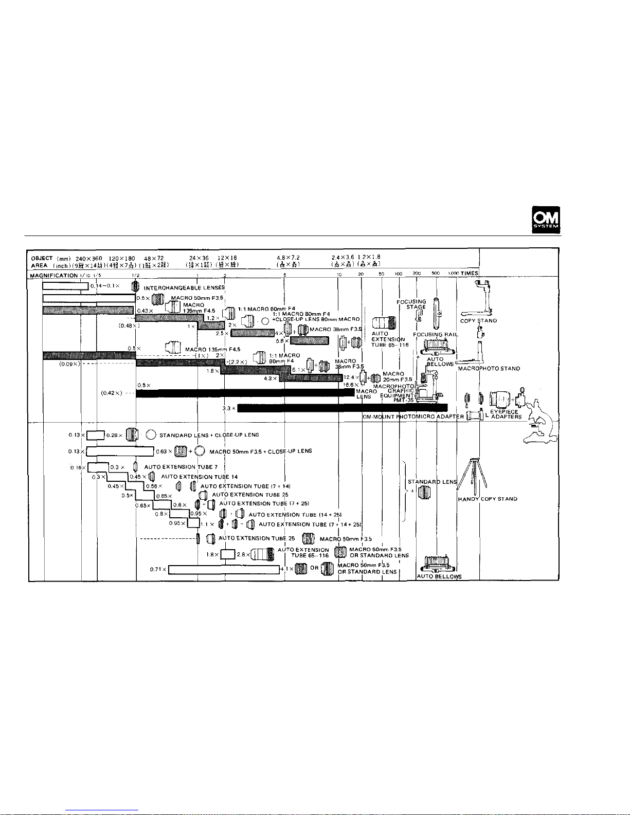
CHART OF PHOTOGRAPHIC RANGES
PROFESSIONAL
METHODS
COMPOSITE
METHODS
GROUPS
ZUIKO
INTERCHANGEABLE
LENS GROUP
MACROPHOTOGRAPHY
GROUP
PHOTOMICROGRAPHY
GROUP
MACROPHOTOGRAPHY
GROUP
94
Page 96
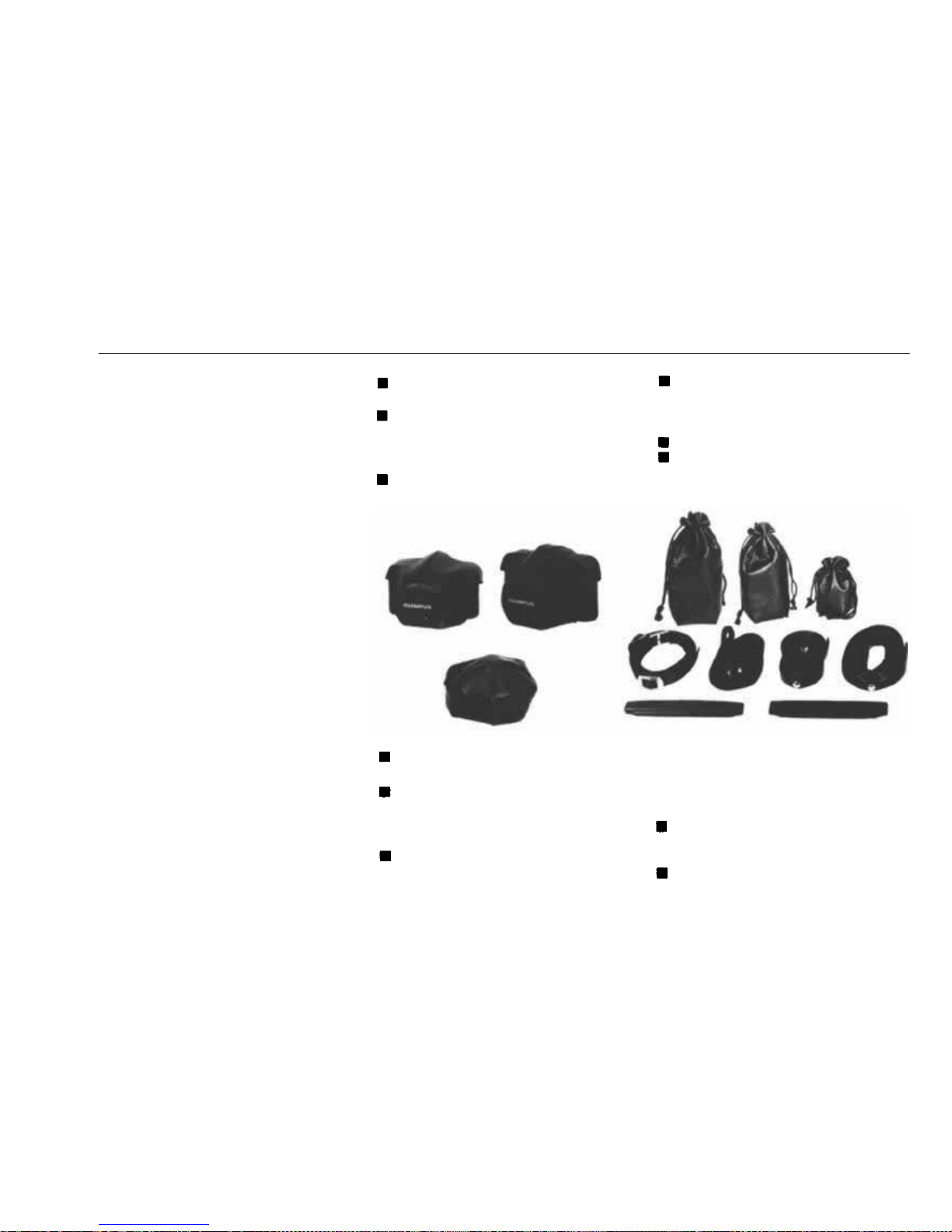
CASE GROUP
CAS E GROUP UNITS
The Ca se Group includes a large
variety of cases that the OM
Body and other components f it
properly.
Compartment cases are specially
made of tough synthetic leather,
designed to perfectly accommodate camera bodies, lenses,
motor drive, electronic flash
units, etc. The adjustable parti-
tions can be rearranged in the
case to suit the photographer's
individual requirements. Soft,
hard and semi-hard cases fit the
OM Body and standard lenses,
with a choice of carrying straps.
Hard Case for OM Body
with F1.8 or F1.4
Hard Case for OM Body
with F1.2
Accommodates the OM Body
with respective standard lens.
Semi-Hard Case for OM Body
with F1.8 or F1.4
Lens Pouch 100
Made of fine leather to contain
a single 100mm lens or smaller
lens or Electronic Flash T20.
Lens Pouch 150
Lens Pouch 200
A fine leather container for a
Semi-Hard Case for OM Body
with F1.2
Soft Case for OM Body with
F1.8
or
F1.4
Accommodates the OM Body
with F1.8 or F1.4 50mm lens.
Soft Case for OM Body
with F1.2
200mm telephoto lens, zoom
lens, or smaller. Also holds the
main body of Electronic Flash
T32.
Lens Pouch 300
Accommodates 300mm and 180
mm telephoto lenses.
Various Shoulder Straps
95
Page 97
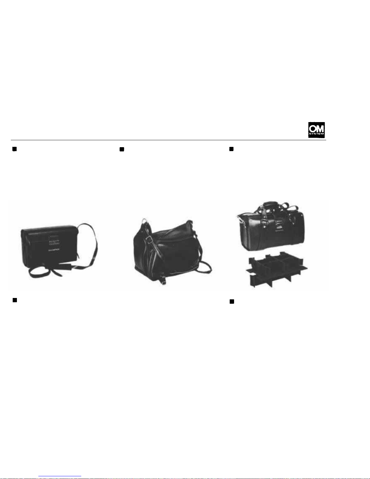
Compartment Case S
A
hard
shoulder
case
with
two
adjustable partitions. Holds OM
Body with two interchangeable
lenses and filters, or with Elec-
tronic Flash T32 and Bounce
Grip.
Compartment Case M
A
soft
shoulder
case
with
parti-
tions and two pockets. Holds
OM Body, three interchangeable
lenses and various auxiliary
equipment including electronic
flash. It also accommodates
clothing and toiletry for travelling, in addition to photographic
Compartment Case L
A hard shoulder or hand-carried
case
with
two
adjustable
parti-
tions. Holds two OM Bodies,
two interchangeable lenses (in-
cluding 300mm telephoto lens),
electronic flash, large format
camera, and other equipment.
Camera Holder for Case M
Besides the camera holder pro-
vided
with
the
Case
M, one
more camera holder is attachable on the right or left wall of
the case as preferred. These
holders can hold two camera
bodies simultaneously.
equipment, permitting camera
and lenses to be taken out freely.
Removable partitions are pro-
vided to hold cameras and lenses
in position safely without their
individual
cases,
permitting
quick lens changing on the cam-
era inside the case.
Partitioned Insert
When inserted into the Compartment
Case
L,
this
unit
supports
the assembly of the Motor Drive
Units. Th e 250 Fi lm Back 1 and
interchangeable lenses can be
stored together with the OM
Body.
96
Page 98
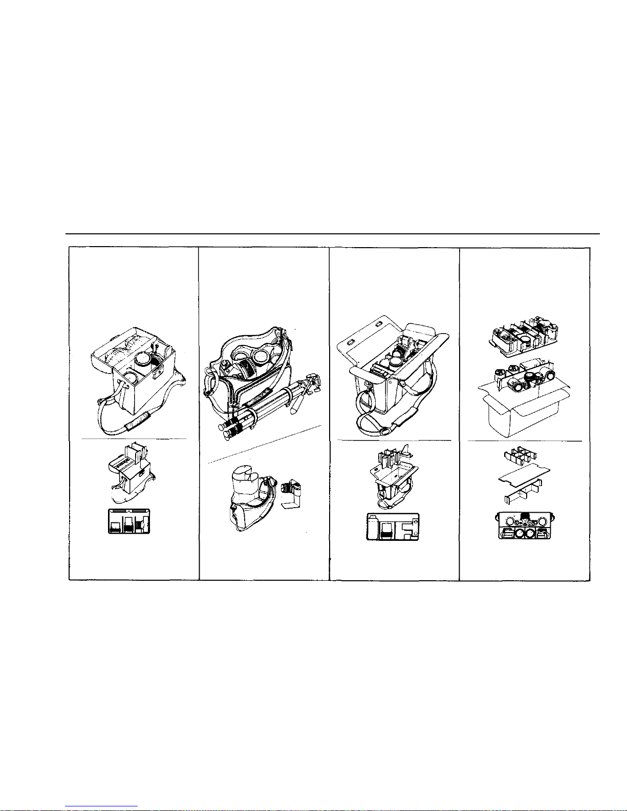
CHART OF CASE GROUP
Compartment Case S
Compartment Case M
Compartment Case L
Motor D riv e
Partitioned Insert
97
Page 99

MAIN SPECIFICATIONS
System: OL YMPUS OM System.
Camera type: 35 m m S i n g l e Le n s Reflex wi th a ut o -
matic exposure control electronic focal plane
shutter.
Film format: 24 mm x 36mm.
Lens mount: OLYMPUS OM Mount, bayonet
type; rotation angle 70°, flange back focus
distance 46mm.
Shutter: Focal plane shutter, automatic exposure
control fro m 120 seconds to 1 /1,000 second
(ASA 100, F1.2, at normal temperature and
humidity). Manual exposure: B, 1—1/1,000
sec., ring mounted control.
Synchro: FR-X switch type contact, incorr.ect
flash prevention. (Accessory shoe mount for
X contact)
Automatic exposure control: Aperture-preferred
automatic exposure control electronic shutter
type. TTL Direct (off-the-film) Light Measur-
ing System. Measuring range: EV-6.5 to EV18
(at ASA 100 with F1.2 lens).
Exposure range: Shutter speeds from 120 sec. to
1/1,000 sec, (at normal temperatures and
humidities). Light sensors: 2 SBC sensors.
Large exposure compensation dial: ±2EV
(within the ASA fi l m speed r ange). Automatic
flash exposure: Direct contacts for TTL Auto
Flash (full automatic flash with T32, T20 or
T10 electronic flash).
Manual exposure: TTL type. Measuring system:
Full aperture center-weighted metering. Meas-
uring range: EV1.5-EV17 (ASA 100 with
F1.2 standard lens). Light sensors: 2 CdS sensors.
Zero-method with needle visible in viewfinder.
Film speed setting: ASA 12—1600, set by lifting
and rotating film speed dial.
Auto/Manual selection: By selector lever.
Power source: Two 1.5V silver oxide batteries
SR44 (Eveready EPX-76 or equivalent).
Battery check: 3-stage battery check lamp (light
emitting diode) indicates f ul l voltage, deplet-
ed charge, and exhaustion of batteries. Shut-
ter lock to limit drainage.
Mirror unlock: Mirror lock-up can be released
simultaneously with battery check.
Viewfinder: Pentaprism type wide-vision finder.
Focusing screens: Wide selection of interchange-
able screens.
Supplied w ith Focusing Screen 1—13 (microprism split image matter type).
Finder view-field: 97% of actual picture field.
Viewfinder magnification: 0.92X at infinity with
50mm- lens.
Apparent field of view : Vertical 23°30', horizon-
tal
35°.
Indicators in viewfinder: 3-stage selector lever.
(Auto : Shutter speed indicator. — Manual: ex-
posure index. — O f f: nothing). Exposure compensation marker. Charge/Auto check lamp
98
Page 100

MAIN SPECIFICATIONS
(with T-series Electronic Flash mounted).
Reflex mirror: Oversize, quick return type ( w it h-
out lock-up).
Film loading: OLYMPUS easy loading.
Manual fi lm advance: Lever type wit h 150° angle
fo r one long or several short strokes, pre-ad-
vance angle 30°, self-cocking, double advance
and double exposure pre vention.
Motor drive advance: Wi t h Motor Drive 1 unit at-
tached, single frame and continuous advance
at speed of 5-frame per second (at exposures
above 1/500 sec., with fresh batteries and at
normal temperature and humidity).
Exposure counter: Progressive type with auto-
matic reset.
Film rewind: Crank type, with rewind release lever
setting, automatic return.
Self-timer: 4—12 second delay lever type with
180° maximum angle; can be stopped and re-
set after actuation.
Camera back: Removable hinge type, with memo
holder.
Interchangeable with Recordata Backs 2, 3
and 250 Film Back 1.
Hot shoe socket: OLYMPUS special Accessory.
Shoe 4 supplied.
Dimensions and weights:
Body only: 136 x 83 x 50mm
(5.35" x 3.27" x 1.97") 520g (18.3 oz)
With F1.8 lens: 136 x 83 x 81mm
(5.35" x 3.27" x 3.19") 690g (24.3 oz)
Wit h F1.4 lens: 136 x 83 x 89mm
(5.35" x 3.27" x 3.50") 750g (26.5 oz)
Wit h F1. 2 lens: 136 x 83 x 97mm
(5.35" x 3.27" x 3.82") 830g (29.3 oz)
99
 Loading...