

Olympus 1, OM-1 Instructions Manual

INSTRUCTIONS
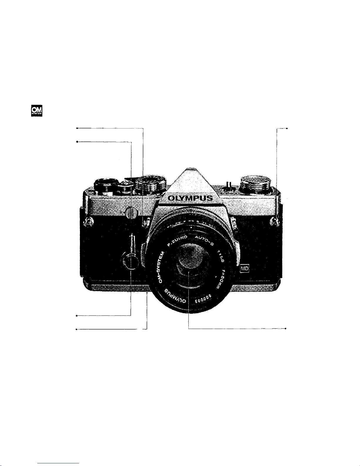
DESCRIPTION OF CONTROLS
Refer to pages in parentheses for detailed
explanations of each part.
Mirror Lock-up Lever
Rewind Release Lever
(P. 29)
Self-Timer
Preview Button
Shoulder
Strap Eyelet
Standard Lens
1
(P. 10)
(P. 29)
(P. 16)
(P. 17)
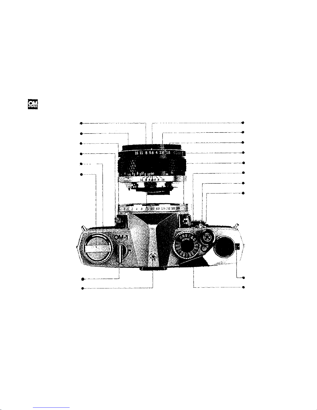
DESCRIPTION OF CONTROLS
The design of the OLYMPUS OM-1 lets you see every camera
control from the top.
Shutter Speed Ring
Lens Release Button
FP and X Flash Selector
Flash Synchronization
Socket
Rewind Knob
/Camera Back Release
Rewind Crank
Depth of Field Scale
Aperture Ring
Focusing Ring
Lens Mount Ring
Body Mount Ring
AS A Film Speed Dial
Film Speed Dial
Release Button
Shutter Release
Button/Cable
Release Socket
Meter Switch Lever
Hot Shoe Socket
Exposure Counter
Film Advance Lever
(P. 11)
(P. 16)
(P. 26)
(P. 26)
(P7•P10)
(P. 10)
(P. 13)
(P. 26)
(P.9)
(P. 9)
(P.17)
(P.11)
(P.15)
(P.
16),
(P.16)
(P.12)
(P. 12)
(P.19)
2
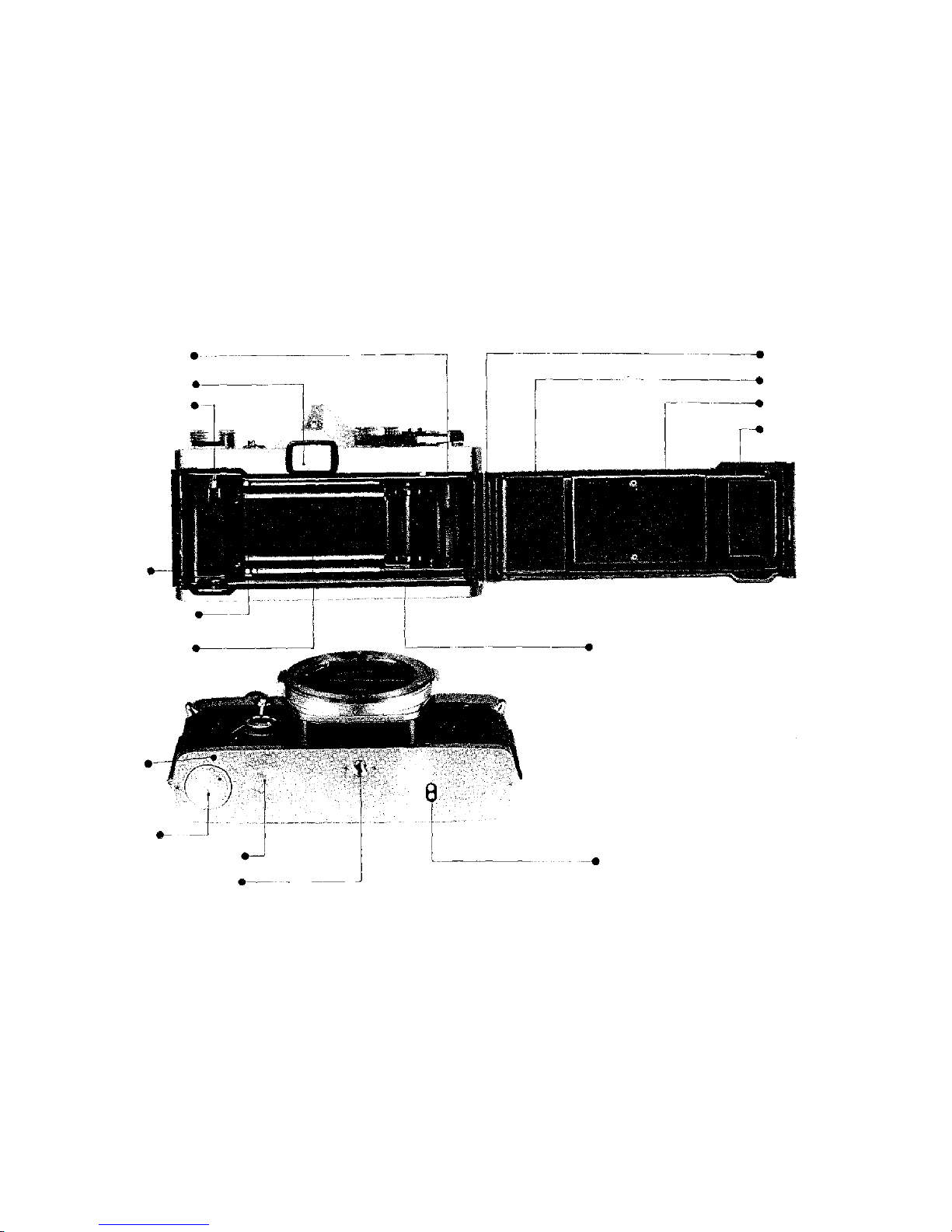
Film Take-Up Spool
Viewfinder Eyepiece
Rewind Shaft
(P.8)
Film Chamber
Film Guide Pins (2)
Shutter Curtain
(P.23)
Guide Pin Hole
Battery Chamber
Motor Drive Socket Cap
Tripod Socket
Camera Back
Release Pin
Camera Back
Film Pressure Plate
Film Cartridge
Pressure Spring
Motor Coupling Terminal
(P. 7)
(P.8)
(P. 11)
(P. 7)
(P.23)
(P.23, 26)
(P. 8)
Dual Sprocket
(P.30)
(P.30)
3

TABLE OF CONTENTS
On
OM-1
Description
of
Controls
......
1
Specifications
............
5
Short Course of Instructions
...
6
Inserting
the
Battery
........
7
Loading
the
Film
..........
7
Front
Lens
Cap
...........
7
Operating the Film Advance Lever 9
The
Exposure
Counter
.......
9
Unloading
the
Film
........
10
Making Double Exposures
....
10
Setting the Shutter Speed Ring . .
11
Setting the Aperture Ring
....
11
Setting the ASA Film Speed Dia l .
12
The
Metering
System
.......
12
Setting
the
Exposure
........
13
Focusing
...............
15
Changing
the
Lens
........ .
16
Infrared
Photography
.......
17
Depth
of
Field
Scale
........
17
Preview
Button
...........
17
Depth
of
Field
...........
18
Holding
the
Camera
........
19
Interchangeable Focusing Screens . 20
Motor Drive Photography
....
21
Operation
of
Winder 1 .......
22
Operation of Basic Motor Drive
Package
..............
23
Flash
Photography
.........
26
Setting
the
Self-Timer
.......
29
Locking
up the
Mirror
.......
29
Changing the Camera Back
....
30
Questions
and
Answers
......
31
Care
and
Storage
..........
32
On OM System
Zuiko Interchangeable Lens Group 33
Table of Interchangeable Lenses. . 35
Interchangeable Lens Group Units 37
Motor
Drive
Group
.........
38
Motor
Drive
Units
.........
41
Finder
Group
and
Units
......
43
Flash
Photo
Group
.........
45
Flash Photo Group Units ..... 48
Macrophotography Group ..... 51
Macrophotography Units ..... 54
Photomicrography Group ..... 59
Photomicrography Units ..... 62
Chart of Photographic Ranges . .
64
Phototechnical
Group
.......
65
Phototechnical
Units
........
68
Case
Group
.............
69
Case
Units
..............
69
4

SPECIFICATIONS
Specifications subject to change witho ut notice.
System:
Camera Type:
Fil m Format:
Standard Lenses:
Lens Mount:
Minimum Focusing Distance:
Lens Accessory Size:
Shutter:
Self-Timer:
Exposure Measurement:
Exposure Range:
Battery:
Film Speed Range:
Viewfinder:
Viewfinder Magnification:
Viewfinder Apparent Field View
Focusing Screens:
Reflex Mirror:
Flash Contacts:
Flash Synchronization:
Hot Shoe Socket:
Film Advance: (Manual)
(Motor Drive)
Exposure Counter:
Film Rewinding:
Camera Back:
Dimensions & Weights:
OLYMPUS OM SYSTEM.
35mm Single Lens Reflex with focal plane shutter.
24mm x 36mm.
50mm F1.8 F Zuiko Auto-S 6 elements in 5 groups.
50mm F1.4 G Zuiko Auto-S 7 elements in 6 groups.
55mm F1.2 G Zuiko Auto-S 7 elements in 6 groups.
OLYMP US OM Mount, bayonet type, rotation angle 70°, flange back 46mm.
45cm (17 3/4") with all standard lenses.
49mm threaded for F1.8 an d F1.4 lenses; 55mm t hreaded for F1.2 lens.
Focal plane shutter, ring mounted control, with speeds from 1 to 1/1000 second plus B:
4—12 second delay lever type; can be stopped and reset after actuation.
Two highly sensitive CdS cells located on either side of the eyepiece provide through-the-lens
open aperture light measurement. Zero-method wit h needle vi s ib l e in viewfinder. On-Off Switch
located atop camera.
EV 2—17 (ASA 100 with F1.4 standard lens).
1.35 volt mercury battery (Eveready or UCAR EPX625, Mallory PX625, or equivalent)
ASA 25-1600.
Pentaprism type wide-vision finder shows 97% of actual picture field; Interchangeable focusing
screens; Visible exposure meter needle.
0.92X
at
infinity
with
standard
50mm
lens.
23° 30' & 35°.
1-13 Microprism/split image-matte type provided. Interchangeable with any of 12 additional screens.
Oversize, quick return type with mirror lock-up control.
FP·X switch type contact.
With electronic flash (X ) 1 to 1 /60 sec.
With class "M" bulbs ( X) 1 to 1/15 sec.
With class "F" bulbs (X ) 1 t o 1/15 sec.
With focal plane bulbs (FP) 1/60 to 1/1000 sec.
Built-in. Easy to attach Accessory Shoe 1 available.
Ratc het t ype f ilm advance. May be advanced in one stroke or several short strokes for a total of
150° rotation, pre-advance angle 30°. Built-in prevention against double advance with double
exposure override capability.
With Motor Drive 1 unit attached, single-frame and continuous advance at speed of 5 frames
per second (at exposures above 1/500 sec., with fresh batteries and at normal temperature and
humidity).
Progressive type from "S" (Start) to 36 and "E" (End). Counter automatically resets to "S''
when camera back is opened.
Rewind crank with automatic-resetting rewind rele as e lever.
Removable hinge type. Interchangeable with Recordat a Back 1 and 250 Film Back 1.
With F1.8 lens:
136mm x 83m m x 81mm (5-3/8" x 3-1/4" x 3-3/16") : 680 gr. (24.0 oz.)
With F1.4 lens: 136mm x 83mm x 89mm (5 - 3/ 8" x 3-1/4" x 3-1/2") : 740 gr. (26.1 oz .)
With F1.2 lens: 136mm x 83m m x 97m m (5-3/8" x 3-1/4" x 3-13/16") : 820 gr. (28.9 oz .)
Body only:
136mm x 83mm x 50mm (5-3/8" x 3-1/4" x 2") : 510 gr. (18.0 oz.)
5
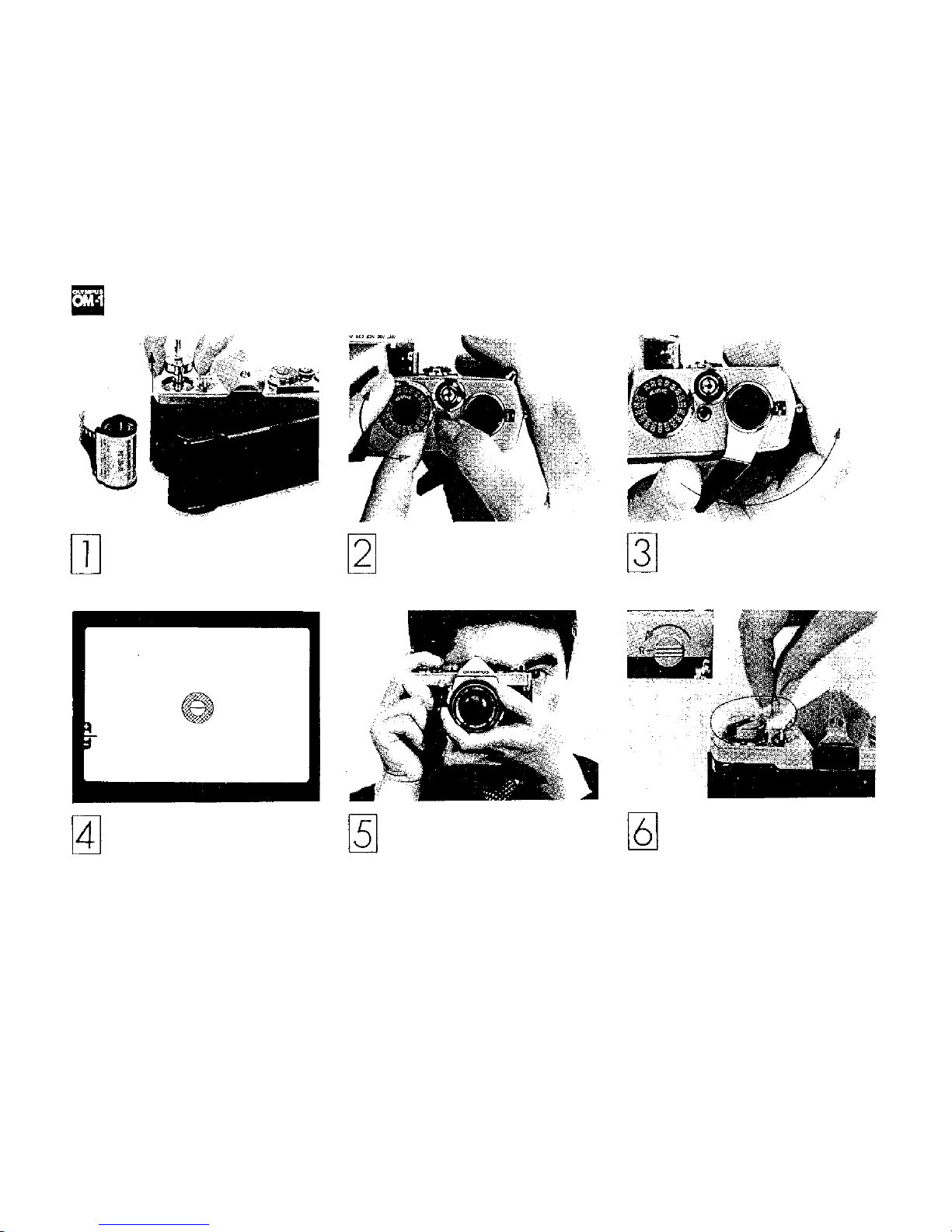
SHORT COURSE OF INSTRUCTIONS
Load the camera (see page 7).
Make sure the battery has been
properly inserted and that the
camera back is closed tightly.
Look through the viewfinder.
Compose and focus. Set the prop-
er exposure (see pages 13, 14, 15).
Set AS A Film Speed (see page 12 ).
Take the picture (see page 19).
Hold the camera steady and release the shutter with a slow,
steady pressure.
Advance the film until the figure
"1" appears in the exposure coun-
ter window (see page 9).
After the entire film has been
exposed, rewind the film back
into the cartridge (see page 10).
(R efe r to each page for detailed operating instructions.)
6
The OLYMPUS OM-1 is supplied with
a 1.35V mercury battery (JIS H-D type)
to power its through-the-lens exposure
metering system. It will last approximately one year depending upon use
and must be replaced with an Eveready
(UCAR) EPX625, Mallory PX625
or equivalent. Substitutes must not be
used. (NOTE; The exposure meter stops
functioning when the battery runs out.
To prolong battery life, make sure the
Meter Switch Lever is in the "OFF"
position when the camera is not in
use.) To insert the battery:
1) Insert the edge of a coin into the
cap of the battery chamber and turn
counter-clockwise until the cap has
been removed.
1. Open the camera back.
Pull up on the rewind knob. A slight
resistance may be felt before the
camera back snaps partially open.
2) Place the battery in the battery
chamber making sure the positive side
(+) is facing out. The exposure meter
does not function if the battery is
inserted incorrectly.
3) Replace the cap tightly.
2. Load th e ca mera.
Insert a film cartridge in the film
chamber and push the rewind knob
back into its original position. It may
be necessary to turn the rewind knob
slightly before it will lock securely in
place.
INSERTING THE BATTERY
LOADING THE FILM
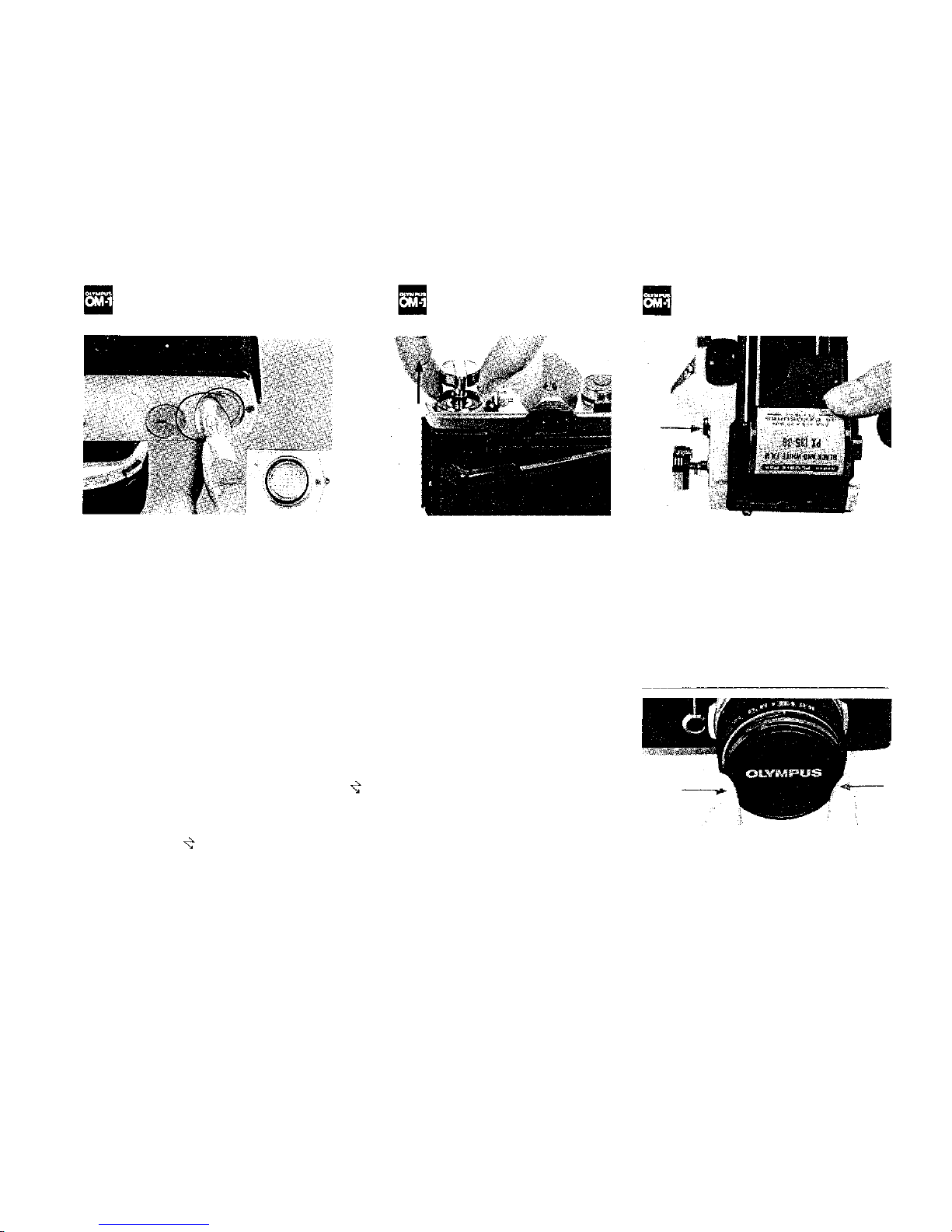
FRONT LENS CAP
7
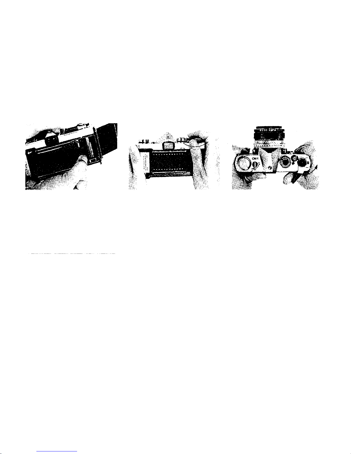
3. Attach the film end to the take-up
spool.
Draw out the film leader and insert it
into one of the slots in the film take-up
spool. Make sure the film is evenly
placed between the film guide pins.
Be careful not to permit the film leader
to protrude out of the opposite slot
when inserted into the spool.
To attach or remove the fron t lens cap,
press the spring-loaded lens cap retain-
ing clips on either side of the cap. The
cap then fits easily over the accessory
thread of the lens.
4. Advance the film.
Advance the film using the film advance lever. Make sure that the film
perforations engage on the sprockets
on both sides.
5. Close the camera back.
Close the camera back until it clicks
in t o place.
6. Tighten the film.
After closing the cover, fold out the
rewind crank and turn it slowly in a
clockwise direction until a slight resist-
ance
is
felt.
This
will
take
up any
slack
in t he film.
7. Check the exposure counter window.
Advance the film and depress the
shutter
release button.
Advance
the
film once more until "1" appears in
the exposure counter window. The
rewind knob will rotate in a counterclockwise direction indicating that the
film is advancing properly.
8
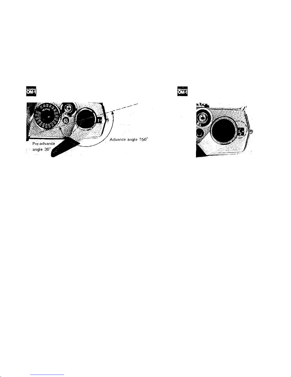
OPERATING THE FILM ADVANCE LEVER
THE EXPOSURE COUNTER
In one stroke the film advance lever:
1) advances the film one full frame,
2) advances the exposure counter, 3)
cocks the shutter, 4) sets the in-
stant return mirror, 5) activates the
automatic diaphragm mechanism and
6) activates double advance and
double exposure prevention mecha-
nism.
To advance the film:
1) Gently pull the film advance lever
away f rom the camera body.
2) Advance the lever to the right as
far as it will go. This can be ac-
complished in a single stroke or in
multiple short strokes.
The exposure counter is designed to
indicate the total number of frames
exposed on the film. Each time the
film is advanced by the film advance
lever, the exposure counter automatically adds one frame to the total.
The counter is indexed in even numbers up to 36 plus "S" (start) and "E"
(end). For easy reference, "S", "E",
and numbers 12, 20 and 36 are indicated in gold.
Whenever the camera back is opened,
the exposure counter automatically
returns to "S".
Refer to page 21 for Motor Drive
Photography.
9
UNLOADING THE FILM
When the entire roll of film has been
exposed (indicated by numbers 12, 20
or 36 on the exposure counter depending on film length), rewind the film.
1) Turn the rewind release lever coun-
ter-clockwise until the red line is
opposite the "R".
MAKING DOUBLE EXPOSURES
Should you wish to make more than
one exposure on the same frame:
1) After taking the first exposure, turn
the rewind knob slowly in a clockwise
direction until it stops to take o ff any
slack
in the film.
2) Turn the rewind release lever counter-clockwise until the red line is
opposite the " R".
2) Fold out the rewind crank and
wind it in the direction of the arrow.
During the rewind procedure you will
feel tension on the crank. When it
turns fr e e the film has been completely
rewound back into the cartridge.
3) Hold both the rewind knob and
rewind
release
lever
firmly
to
prevent
them from turning and advance the
film advance lever. The shutter will
then be cocked for the next exposure
of the frame, without the film being
advanced.
4) Depress the shutter release button
with a slow, steady pressure.
5) After completing the multiple ex-
3) Open the camera bac k b y pulling up
on the rewind crank and remove the
film cartridge. Keep camera and film
out of direct sunlight.
IMPORTANT: Do not force the film
advance lever if the film has been fully
exposed. If there is some resistance,
rewind the film to prevent tearing.
posure, cover the lens with a lens cap,
advance the film and shoot a blank
frame to avoid overlapping.
You can make as many multiple exposures as you like by repeating the
above procedure. With each exposure
on the same frame (the exposure
counter adds one), the likelihood of
slippage is increased. Practice is re-
quired in order to obtain good results.
10

The length of time that light is allowed
to strike the film is controlled by the
focal plane shutter. The shutter consists of two opaque "curtains" which
travel across the opening and allow
light
to
reach
the film.
The
speed
and
coordinated movement of these curtains determine in frac tion s of a second
the exposure time for your picture.
For example, 1000 on the shutter
speed ring indicates 1/1000 of a second
and 60 indicates 1/60 of a second. The
figure 1 indicates one full second. The
B (Bulb) setting is used for longer time
exposures. At this setting the shutter
will remain open as long as the shutter
release button is held down. For ex-
posures less than 1/30 of a second, it is
advisable to use a cable release, tripod
or other steadying devices to avoid
camera movement which can result in
blurred or fuzzy pictures.
To set the shutter speed turn the
shutter speed ring in either direction
until the desired number clicks into
place opposite the reference dot on the
lens barrel. Set the ring only at click-
stop positions as no in-between settings
can be used. Shutter speeds may be set
before
or
after
advancing
the
film.
NOTE: Speeds from "B" to "60" are
indicated on the ring in blue as an easy
reference to "X" flash synchronization.
The amount of light allowed to strike
the film is represented by "F" numbers
or "F" stops engraved on the aperture
ring. The higher the F number, the
smaller
the
lens
opening
(less light);
the
lower the number, the larger the lens
opening (more light). When setting the
aperture ring you can use either the
click-stop positions or any in-between
settings to obtain precise exposure.
All lenses in the OLYMPUS OM SYS-
TEM (other than specialized lenses)
provide fully automatic diaphragm
control allowing you to focus and
compose
your
picture with
the
lens
at
maximum aperture or "wide open."
The diaphragm will au t omatically stop
down to the preselected F stop at the
moment of exposure and immediately
re-open when exposure is completed.
SETTING THE SHUTTER SPEED RING
SETTING THE APERTURE RING
11
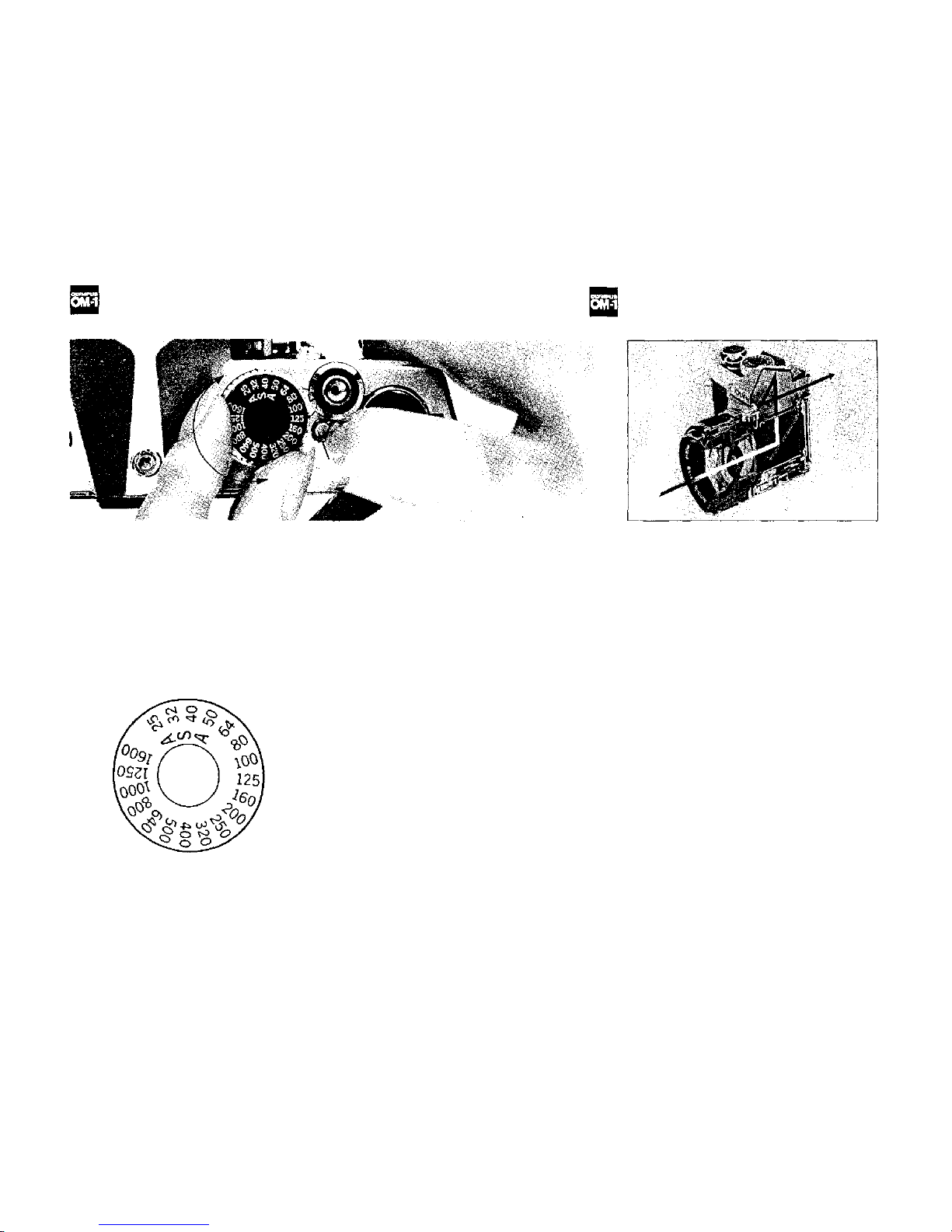
SETTING THE ASA FILM SPEED DIAL
THE METERING SYSTEM
Setting the correct ASA film speed on
the camera is one of the most impor-
tant factors in determining exposure.
In order to obtain properly exposed
pictures, the correct ASA film speed
must be set on the ASA film speed
dial. To set the dial:
1) Pull the film advance lever slightly
away from the camera body.
2)
Press
the
film
speed
dial
release
button and turn the film speed dial
until the ASA rating for the film being
used is opposite the black line engraved
on the outer ring of the shutter release
button.
3)
Release
the
button
making
sure
that the dial is securely in place and
does not move.
The OLYMPUS OM-1 incorporates a
built-in, wide-open exposure metering
system which uses two highly sensitive
CdS cells with one postioned on each
side of the eyepiece. These cells measure the actual amount of light enter in g
the lens, placing the greatest emphasis
at the center of the picture area.
Measurements are taken with the lens
diaphragm at maximum aperture (wide
open) allowing you to take full advantage of a brighter viewfinder when
focusing and composing your picture.
The OM-1 metering system operates as
above with all OM System camera
lenses (except a few special lenses)
regardless of the focal length, filters,
etc.
12
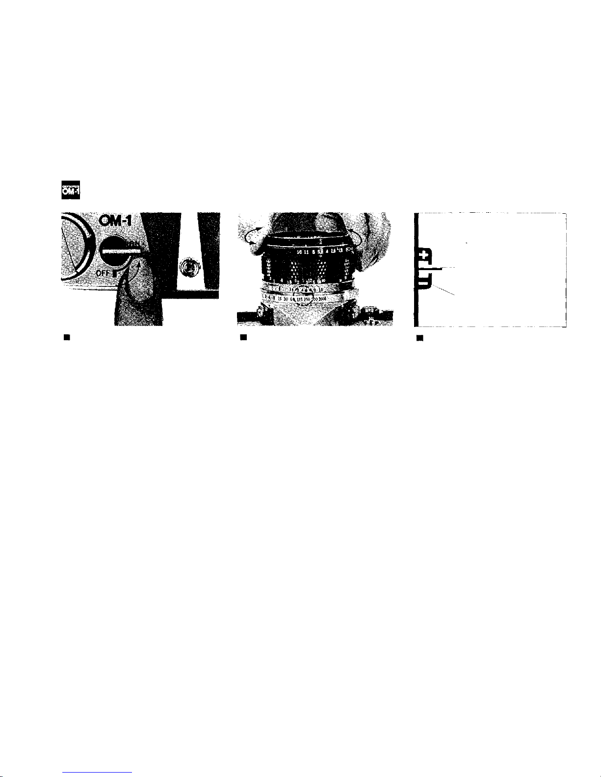
SETTING THE EXPOSURE
Activating the Meter
The OLYMPUS OM-1 metering sys tem
is directly coupled to the shutter speed
ring, aperture ring and ASA film speed
dial.
To activate the meter, move the meter
switch lever at the top of the camera to
the "ON" position. To prolong battery
life, it's a good idea to return the lever
to the "OFF" position when the cam-
era is not in u se.
Preselecting the Shutter Speed
Should you wish to select a shutter
speed to meet a specific photographic
situation (for example, to stop fast
action, eliminate camera shake, etc.):
1) Turn the shutter speed ring until
the desired speed is opposite the red
reference dot on the camera lens.
2) Look through the viewfinder and
turn the aperture ring until the needle
lines up in the center of the index. For
fine exposure adjustment you can use
any intermediate F stop position on
the aperture ring.
3) If the needle will not align proper-
ly, select a new shutter speed. To
correct over-exposure (+), try a faster
speed; to correct under-exposure (–),
try a slower speed.
Exposure Meter Needle
Exposure Meter Index
Preselecting the F Stop
Should you wish to preselect the F
stop (for example, to control depth of
field for greater creative impact):
1) Turn the aperture ring until the
desired F stop is opposite the white
index mark at the front of the lens
barrel.
2) Look through the viewfinder and
rotate the shutter speed ring until the
needle lines up as close as possible to
the center of the index. Make su re that
shutter speed meets the other require-
ments of th e situation.
3) Make the final exposure adjustment
by turning the aperture ring slightly
until the needle aligns exactly in the
center of the index.
13
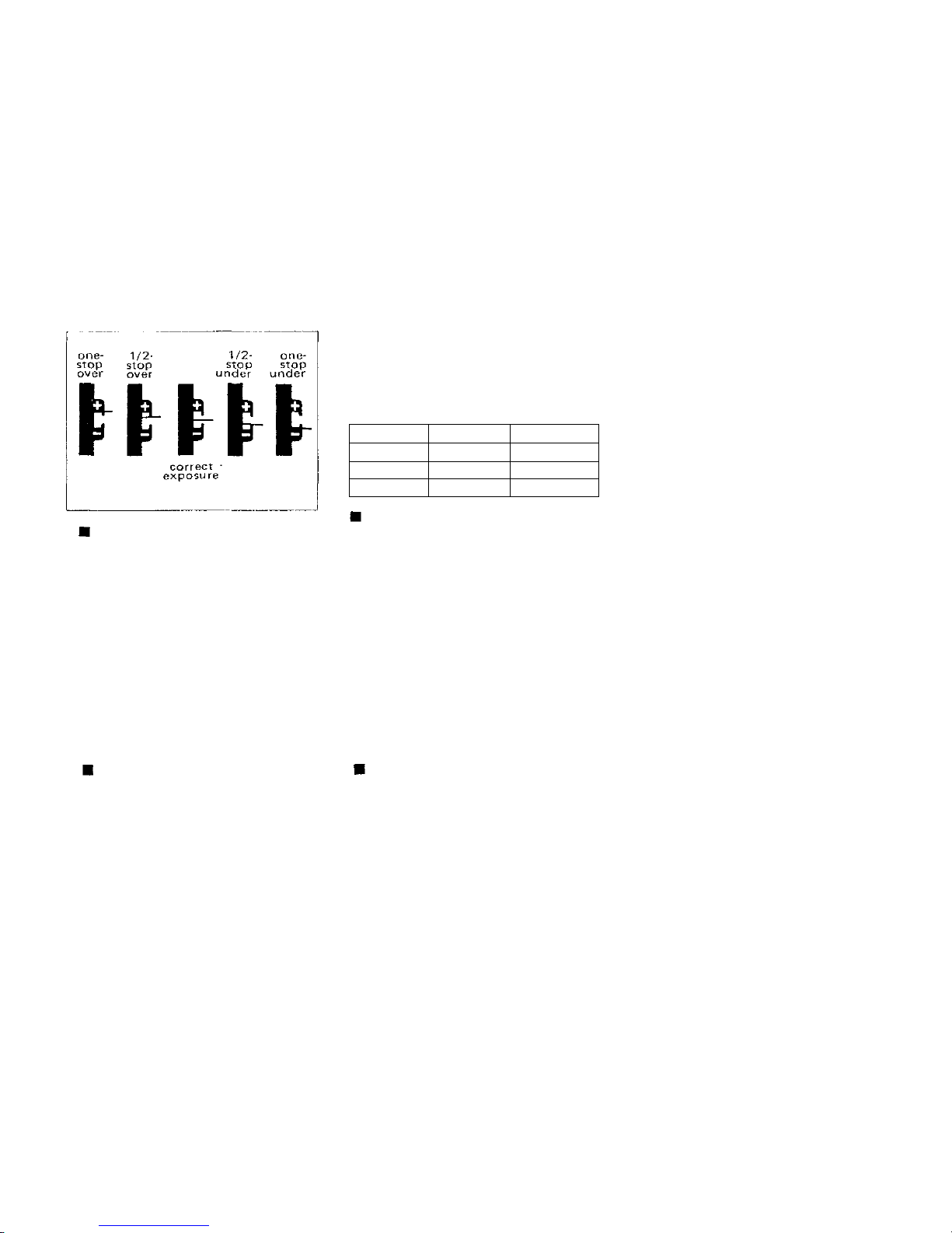
Making Intentional Over- or Under-
exposures
You can make intentional over- or
under-exposures to meet special lighting requirements (such as backlighting,
sidelighting, etc.) by using the central
index in the viewfinder as a guide.
When the needle swings towards the
(+) position, it indicates over-exposure.
When it swings towards (–), it indicates under-exposure. The exact F
stop-n e e d le relationship is shown in the
above diagrams.
Caution in Low-light Exposure
Metering
The meter's e x po s ur e range is EV2—17
(ASA 100 with F1.4.) The combina-
tions listed below indicate the lowest
measurable limit in dealing with dark
subjects.
Below
this
limit
or
with
the
meter
switc h at O FF, when the aperture ring
or shutter speed ring is rotated, the
needle might sometimes swing but the
meter will not work.
Lens
50mm F1.8
50mm F1.4
55mm F1.2
F/Stop
Fully open
Fully open
Fully open
Shutter Speed
1/2 sec
1/2 sec
1/2 sec
Stop-down Exposure Readings
When using the OM-1 in conjunction
with the extension tubes, bellows or
the Zuiko Shift Lens it is necessary to
take meter readings with the lens stop-
ped down. After setting the desired
aperture on the aperture ring, stop
the lens diaphragm down and look
through the viewfinder. Rotate the
shutter
speed
ring
until
the
needle
aligns within the center of the index.
(See the instructions on Preselecting
the F Stop, page 13.)
Special Exposure Techniques
1) Backlighting and Sidelighting
When the most important area of the
picture is much darker than the general
picture
area
(strong
light
hitting
the
main subject from behind or from the
side)
the
meter
will
have a tendency
to
read the brightest part of the picture
leaving the main subject under-exposed.
To compensate for this, move in
towards the subject until most of the
subject image appears in the viewfinder
and take your meter reading. After
setting the exposure, return to your
original position to take the picture. If
this procedure cannot be followed, you
can obtain approximately the same
results by simply opening your lens
one full F stop over the indicated
meter reading. (NOTE: With backlighting or sidelighting, it's always a
good idea to use a lens hood to
eliminate unwanted glare.)
2) Strong Frontlighting and Deep
Shadows
When taking a picture of a bright
subject against a dark background
(spotlights, deep shadow areas, etc.)
the meter has a tendency to read the
darkest part of the picture leaving the
main subject over-exposed. To compensate for this use the same procedure
for setting exposure as outlined for
backlighting. You can also approxi-
mate the proper exposure by holding
your position and closing the lens
down one full F stop from the indicated meter reading.
14
Microprism
Rangefinder Spot
Matte Field
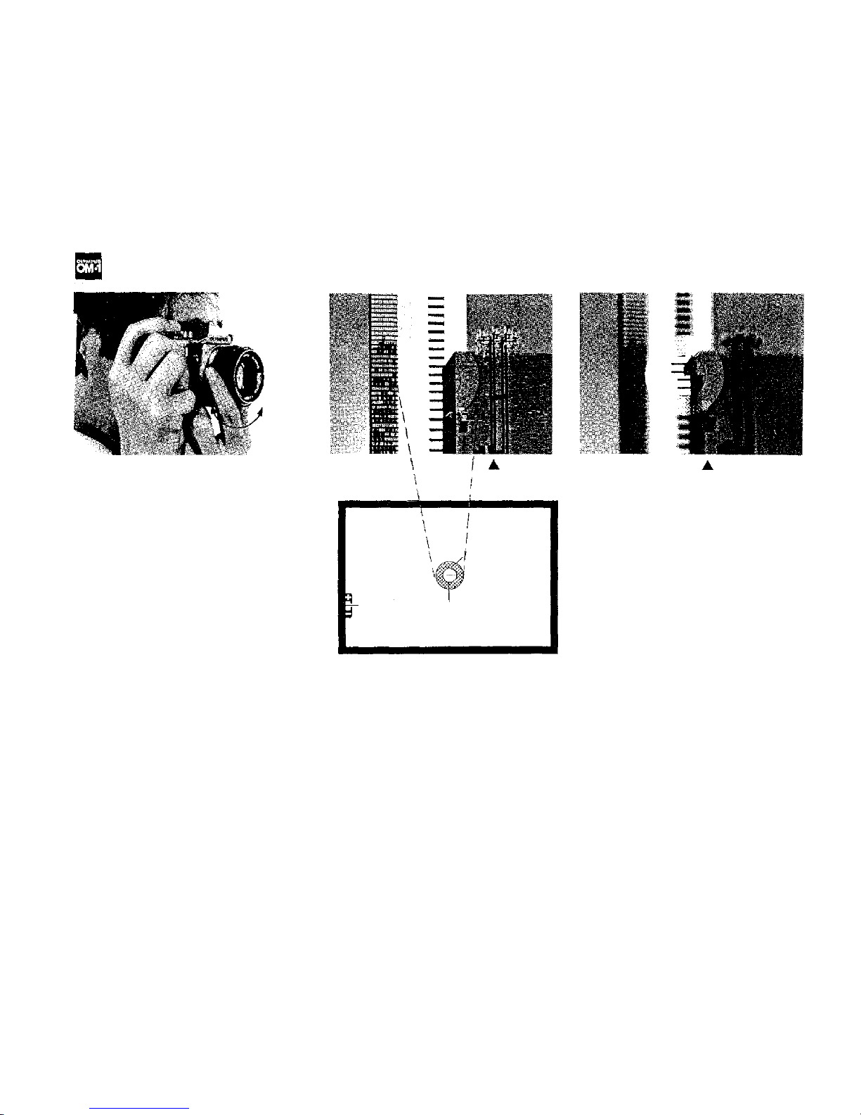
FOCUSING
The OLYMPUS OM-1 comes equipped
with
the
standard
Focusing
Screen
1-
13 (microprism/split image-matte
type) which is designed to make focus-
ing quick and easy. To focus, look
through the camera viewfinder and turn
the
focusing
ring
in
either direction
until split vertical lines of the subject
image in the rangefinder are aligned or
the "shimmering effect" of the microprisms disappears. If you are focusing
on the matte area, the subject is in
focus when the image is sharp.
* You can determine the distance be-
tween the subject and the film plane
by reading the distance scale on the
focusing ring after you achieve critical
focusing. The actual distance is indi-
cated opposite the red central index
mark on the lens mount ring; the white
scale indicates this distance in meters
The OM-1 viewfinder takes in 97% of
the actual picture area for added convenience when composing your pictures.
and the orange scale indicates this dis-
tance in feet.
In focus
Out of focus
15
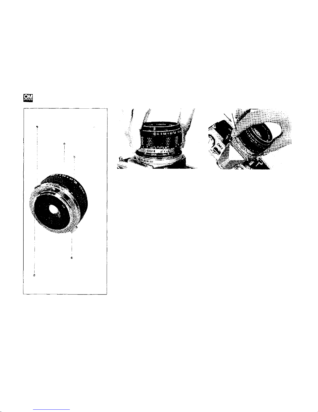
CHANGING THE LENS
To mount the lens, grasp the lens
firmly and align the red dots on the
lens flange and the camera mount ring.
Turn the lens clockwise until it locks in
place.
The
lens
release button
will
spring up and you will hear a positive
"click"
when
the
lens
has
been
fully
engaged. Do not apply pressure to the
lens release button during the mounting
procedure.
This will
assure
proper
coupling between the lens and the
meter.
The bayonet mount of the OLYMPUS
OM-1 allows you to change lenses
quickly and easily.
To detach the lens, press down on the
lens release button and turn the lens
counter-clockwise. Grasp the lens firmly and remove it from the camera
body.
Protect your lens and camera! Always
attach the front and rear lens caps
when the lens is removed from the
camera to prevent any possibility of
damage. Never leave the camera body
in direct sunlight with the lens removed and, if you plan to store the
camera without the lens, the use of a
bo dy cap is recommended.
Lens Release Button
Meter Coupling
Lens Mount Ring
Depth of Field
Preview Button
Automatic Diaphragm Lever
16
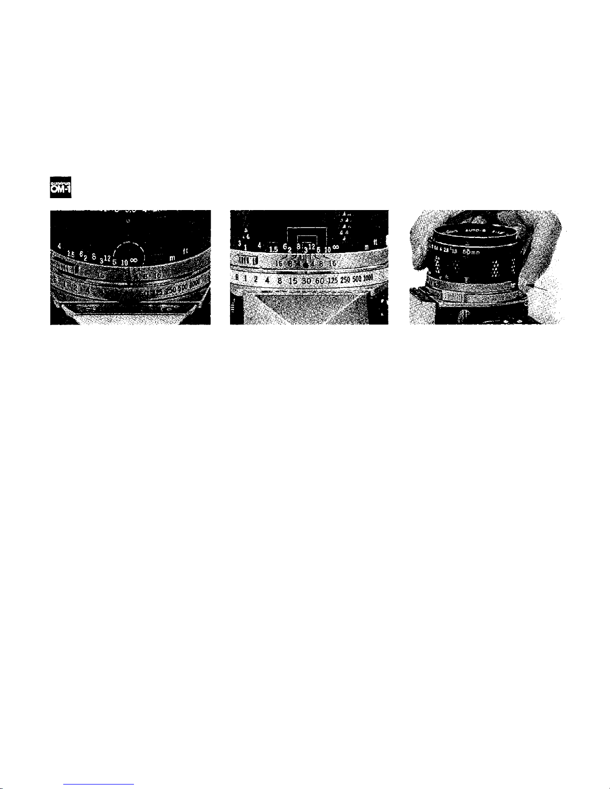
INFRARED PHOTOGRAPHY/DEPTH OF FIELD SCALE/PREVIEW BUTTON
The OM System lenses are provided
with an infrared index mark engraved
in red on the depth of field scale to the
right of the reference dot. When shooting with infrared film, focus normally
on your subject without the red filter
on and read the subject distance on the
distance scale. Then, turn the focusing
ring to the right until the distance
reading is opposite the infrared index
mark. Your lens will then be in focus for
average infrared photography. Shoot
with the red filter on. In the above
picture the red index is set at i nfini ty.
The double series of numbers engraved
on the depth of fie ld scale represents F
stops: F4, F8 and F16. Onc e yo u have
focused on your subject, all objects
within the distance range indicated on
the lens distance scale between the
marks for the F stop you have selecte d
will have acceptable sharpness.
For example, in the above picture the
camera-to-subject distance is 3m (10ft)
and the lens is set at F16. If you read
the distance scale at the points op-
posite the engraved "16" on both sides
of the reference dot, you will find that
the depth of field is from 1.9m (6ft) to
7m (23ft). The depth of field can be
visually verified by pressing the depth
of field preview button.
When you wish to see which objects
fall within the acceptable zone of
sharpness (depth of field), press the
preview button on your lens. The
diaphragm of the lens will stop down
to the preset F stop enabling you to
see the depth of field in the camera
viewfinder.
* If you jerk the preview button while
depressing the shutter button half-
way down, the shutter might get
released. Gently push and release the
preview button to avoid accidentally
releasing the shutter.
17
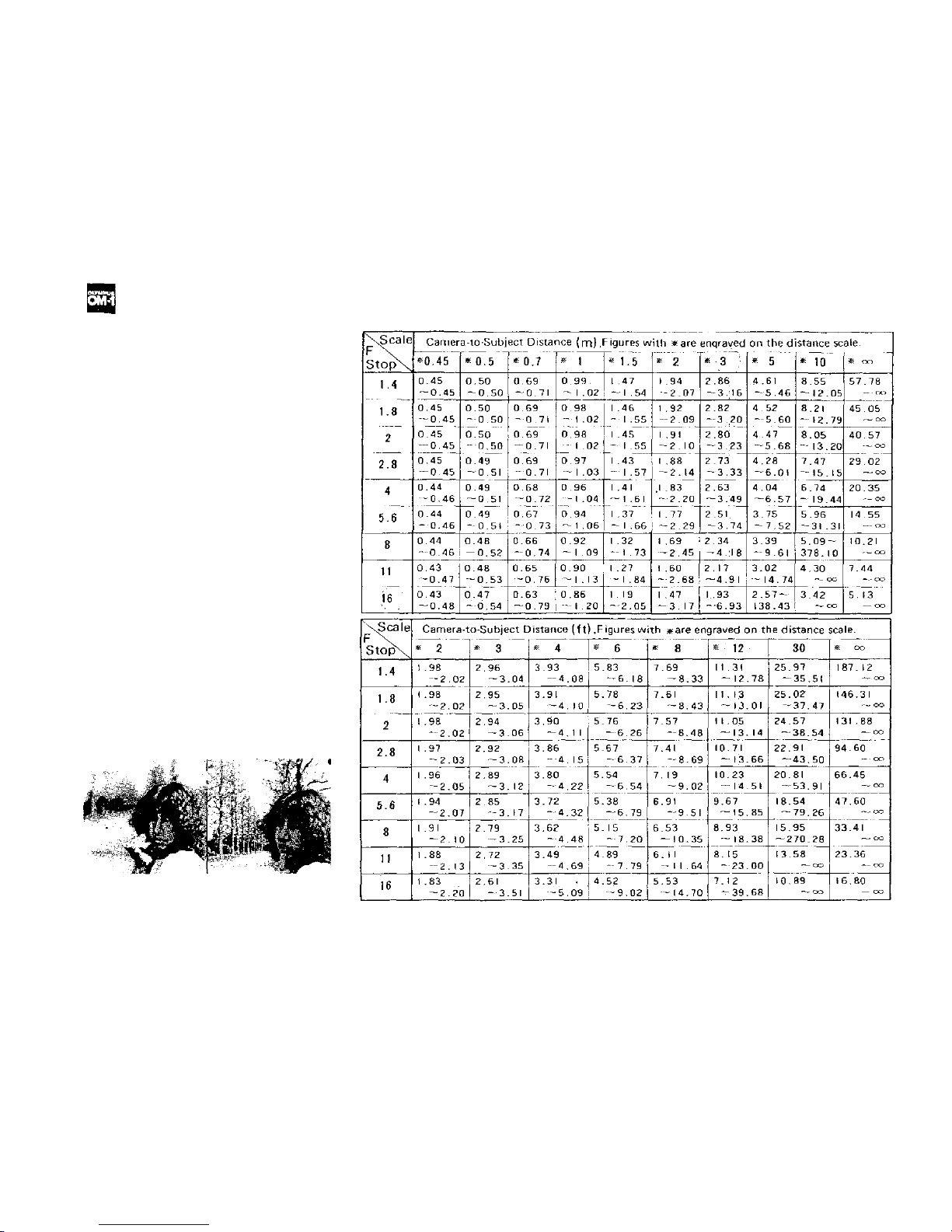
DEPTH OF FIELD
Depth of fie ld is the area of acceptable
sharpness in front of and behind t he
subject in focus. This depth is deter-
mined by the F stop you have selected
and the distance from the subject in
focus to the film plane. As you get
closer to your subject or as you open
your lens (e.g. from F22 to F2.8) the
depth of field becomes shallower. By
stopping your lens down (e.g. from
F2.8 to F22) or getting farther away
from your subject this depth of field or
zone of acceptable sharpness can be
increased.
Another factor in determining depth of
field is the focal length of your lens. A s
a rule the shorter the focal length, t he
greater the zone of acceptable sharpness. The longer the focal length, the
shallower this zone becomes.
The table above shows that when the
camera-to-subject distance is 3m (10ft),
the depth of field at F16 ranges fr om
1.93m ( 6f t) to 6.93m (23ft).
F1.8 (1/1000 sec.)
Depth of Field Table (F1.8 & F1.4 Standard Lenses) Circle of least confusion 1/30 mm
F16
(1/30
sec.)
18
19
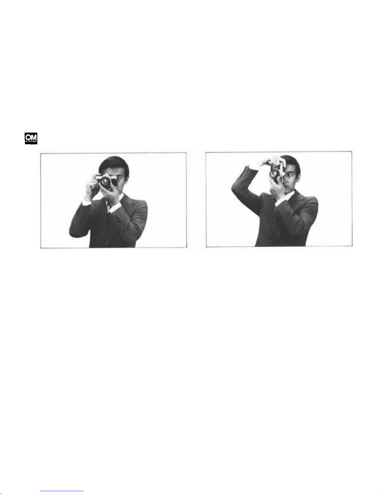
HOLDING THE CAMERA
Proper camera handling is important in assuring
the sharpest possible pictures.
Holding the Camera Horizontally
Keep both elbows close to the body, to steady
the camera.
Putting the Camera into Operation
The aperture ring, focusing ring and shutter speed
ring are so arranged as to enable one hand opera-
tion right up to the moment the shutter is released.
Hold your breath at the moment of shutter release.
Transport the film advance lever with your right
thumb and squeeze the release button smoothly
using the cushion, not the tip, of your index
finger.
Holding the Camera Vertically
For vertical shooting, keep one elbow close to
your body and press the camera tightly against
your forehead.
NOTE: Steady yourself against any nearby sup-
port (such as a tree, fence, or wall) whenever pos -
sible.
NOTE: For telephotography, or slow shutter
speed photography, it is recommended that you
use a tripod and hold the camera steady with
you r hands.
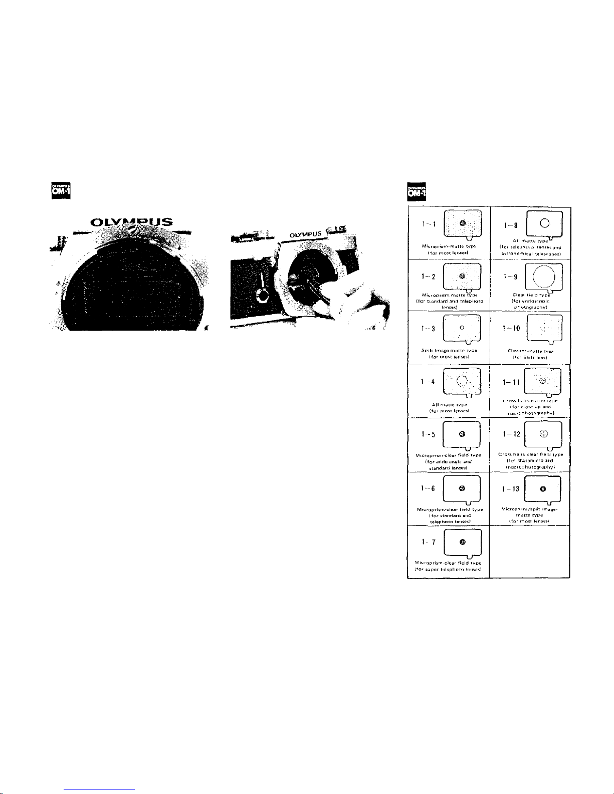
INTERCHANGEABLE
FOCUSING SCREENS
(Handle with extreme care.)
List of Optional Focusing
Screens
The OM System interchangeable fo-
cusing screens provide you with the
ultimate in focusing versatility. Optional screens are available to suit
virtually every picture-taking situation.
The
focusing
screens
come
with
a
special tool. To remove the focusing
screen:
a) Detach the camera lens from the
camera body (see p. 16).
b) Use the special tool provided to
push up on the release catch underneath the top ledge of the mirror
box (see the photo above). This
allows the screen and screen frame
to drop down.
c) Remove the screen from inside the
camera by gripping the tip of the
screen with the tool as shown.
d) To install the screen, fit it in the
frame and push the frame upward
gently until it clicks into place.
Gently shake the camera body to
make sure the screen is held securely in place.
IMPORTANT: Although the above
procedure could be done with fingers,
it is recommended that you use the
special tool supplied. Changing focus-
ing screens is a procedure to be han-
dled with great care. Trying to change
screen with your fingers can result in
fingerprints and costly damage to the
surface of the screen, the prism, or the
mirror. Should this occur, cleaning or
repair MUST be handled by an authorized service center. Such damage is not
covered by the product warranty.
* See page 44 for
details.
(Specifications
subject to change
without notice.)
20

MOTOR DRIVE PHOTOGRAPHY
Motor Drive has many exciting recreational, professional and scientific
applications including sports photo-
graphy, action portraits, copying litera-
ture, wildlife photography and time-
lapse photography.
By automatically advancing the film
and cocking the shutter, the motor
drive not only frees the photographer
from the burden of manually advancing the film, but also allows him to
shoot a series
of
pictures
that
might
otherwise be lost through the timeconsuming manual method.
The Motor Drive package is specifically
tailored to the compact size of the
Olympus OM-1. Extremely small and
lightweight, the Motor Drive 1 mounts
directly to the camera base creating
one of the most compact and ma-
neuverable
motor
drive
systems avail-
able. Although reduced in size and
weight, the OM System Motor Drive
Group excels in performance. The basic Motor Drive package can provide
operation up to 5 frames per second in
optimum conditions*, has single release capability and offers motor drive
sequence applications over a wide
range of shutter speeds.
The following instructions (pp. 23-25)
are for the basic motor drive system
consisting of the Olympus OM-1, Motor
Drive 1, and M.18V Control Grip 1 or
M.15V Ni-Cd Control Pack 1.
*Optimum conditions: Maximum
framing
rate
varies
with
temperatures,
types of films and batteries, etc. The
word optimum implies such conditions
in which sequence filming is made at
normal temperatures at shutter speeds
of 1/500 of a second and faster, using
the M. 18V Control Grip 1 containing
fresh superpower manganese batteries.
Cartridges with smooth film moving
must als o be used.
21
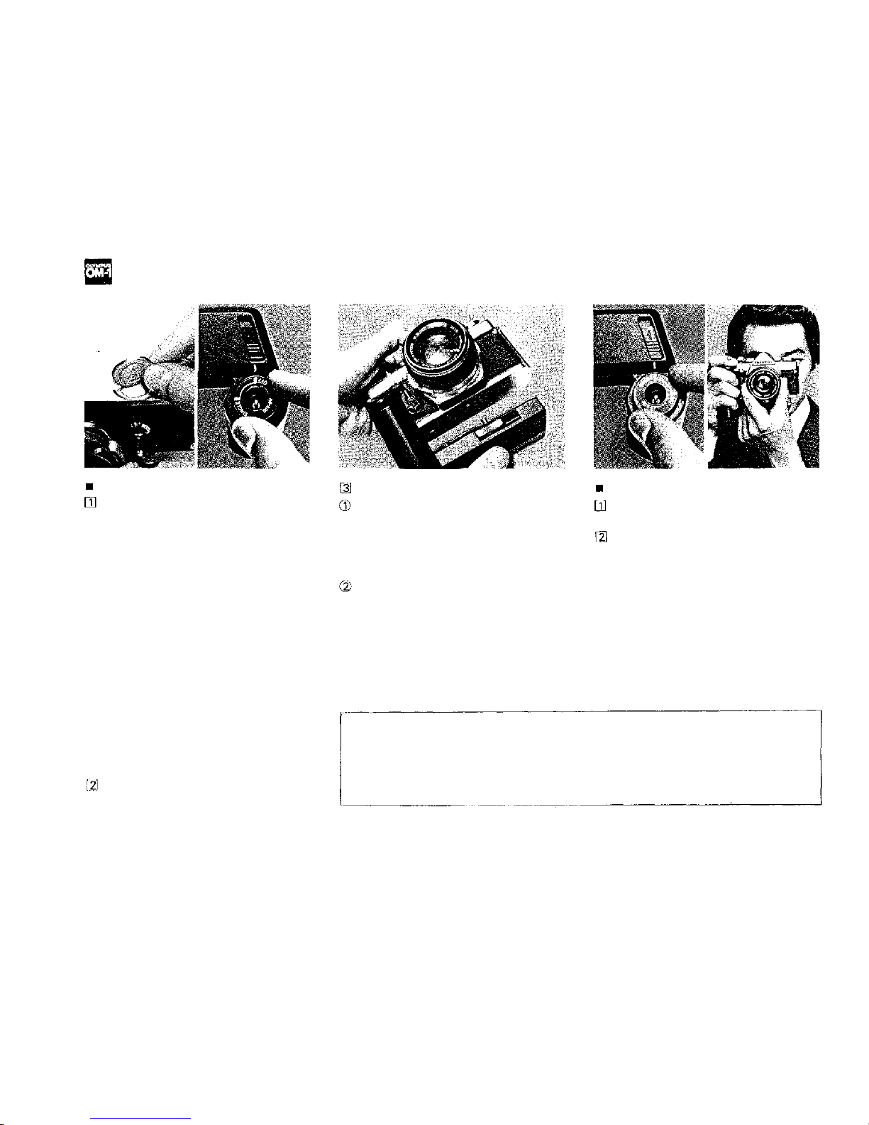
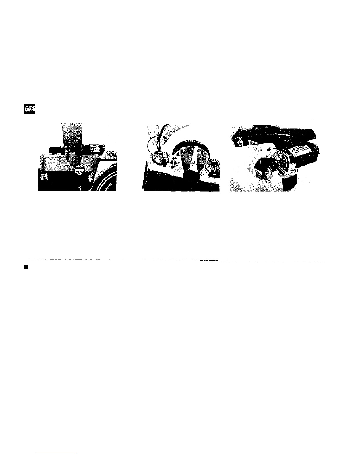
OPERATION OF WINDER 1
Attaching the Winder 1
Remove the motor drive socket cap.
Remove the motor drive socket cap
from the camera base plate by rotating it counter-clockwise with a coin
until the index dot on the cap is
aligned with the index dot on the
camera.
To replace the cap, align the index
dot on the cap with the index dot on
the camera, and turn the cap clockwise with a coin until the index dot
on the camera is aligned with the
groove on the cap.
(The removed motor drive cap can be
stored in the socket cap storage positioned on the underside of the battery
holder compartment.)
Pull up and rotate the switch dial to
the "OFF" position.
Attach the Winder 1
Remove the M.6V Battery Holder 1
from inside t he winder, insert four 1.5
V
penlight
(AA)
size
batteries
into
the
battery holder, and put it back into the
compartment.
Insert the motor drive guide pin into
the guide pin hole on the camera base
plate. To assure proper con ne ction, ad-
just the position of the Winder 1 until
it is flush with the camera. Turn the
clamping screw clockwise until the
Winder 1 is securely attached to the
camera base plate.
Taking the pictures
Pull up and rotate the switch dial
to the "SINGLE" position.
Press the shutter release.
The Winder 1, designed primarily f or
single-frame shooting, operates on
four self-contained AA batteries and
is extremely compact and light. The
unit advances the fi lm and cocks the
shutter as soon as exposure is made
(wind-on time—0.3 sec.), so that
the photographer can always be ready
to freeze the subject at the right
moments.
22
 Loading...