

Page 1
SELF TESTING MAINTAINED EMERGENCY ILLUMINATION SIGNS WITH WHITE LEDs
TECHNICAL CHARACTERISTICS (for LED MODULE specifications see page 4)
SLD-44/DZ
440x240x15mm
1380gr.
Mains voltage
Maximum power consumption
Battery (Ni-MH)
Battery protection
Indications
Recharging time
Minimum emergency duration
Light source intensity (230V) / (emerg.)
Degrees of cover protection
Produced in accordance with
Operation temperature range
Relative humidity
Construction materials
External panel's dimensions
External unit’s dimensions
Typical weight
Guarantee
Thank you for your trust in our products
Olympia Electronics - European manufacturer
SLD-28/DZ
SLD-34/DZ
220-240V AC/50-60Hz
9.5 VA9 VA
3.6V/1.5Ah
Overcharging and deep discharging protection
Charge LED, Lamp LED, Fault LED, Test Button
24h
3h
100lm /100lm 125lm /125lm
IP30
EN 60598-1, EN 60598-2-22, ΕΝ 55015, ΕΝ 61547, ΕΝ 61000-3-2, ΕΝ 61000-3-3
5 to 40 C
o
up to 95%
ABS/PC, aluminum, Acrylic plate
280x120x15mm
340x190x15mm
289x65x34mm
680gr.
1020gr.
3 years (1 year for the battery)
Description The Automatic Autonomous Test is conducted and measures the
The luminaire consists mainly from two parts. luminaire`s back up operation. This test is conducted automatically
The body, where all the electronics are located and the lamp-head every six months. In order to be performed, the mains power supply
where the indication sign and the high efficiency LEDs are located. and the battery should be connected (the battery should be charged).
Maintained/Non maintained selection capability completely charged. If during the Automatic Autonomous Test the
Power on the device and press continuously the TEST button for 10 luminaire’s duration is lower than the nominal, then the battery must
seconds, until the led strip turns off. Release the button and after a be replaced.
short emergency test, the device operates as non-maintained. If you
want to restore the previous condition (maintained operation), press Back Up Operation
continuously the TEST button for 10 seconds, until the led strip The autonomous duration of battery during emergency mode is at
lights. Release the button and after a short emergency test, the least the one that is stated in the list of the first page. During
device operates as maintained illumination sign. emergency mode, a LED strip test is also performed.
Installation Resetting Errors
To install the illumination sign follow the installation instructions on Push the Test button for >5 seconds, to delete all the indicated LED
page 2. errors. Then the luminaire enters regular operation mode.
Battery Charging Indication LED status (with connected mains power supply).
The battery charging is completely controlled. In this case, is Charge
achieved the perfect battery maintenance , as well as the elongation On: Good charge current.
of its duration. When the battery has completely charged, it charges Οff: No battery (No charging current or disconnected battery).
with a maintenance current.
Battery Cut-off Off: Good LED strip or back up circuit.
The luminaire enters in this operation when Battery Fault
the mains power supply fails and battery has lost its energy. During Οff: Battery OK.
this operation the luminaire enters the idle state and battery
consumption is negligible, in order to be protected from deep Blink (With Charge LED ON): Autonomy or low battery problem (the
discharge. battery must be replaced).
Manual Test No charging current or disconnected battery.
The manual test can be conducted only if the mains power supply
and the battery is connected. By pressing the test button briefly an
operation test is initiated. During this test period all indication LEDs
are OFF.
If the battery is not charged, the test is postponed until the battery is
Lamp Fault
Οn: Faulty LED strip or back up circuit.
Blink (With Charge LED Off):
Automatic Test
This test includes all the operations that provide the manual test and
is conducted automatically every 15 days. In order to be performed,
the mains power supply and the battery should be connected.
Automatic Autonomous Test
Page 1 from 4
922044000_09_027
Page 2
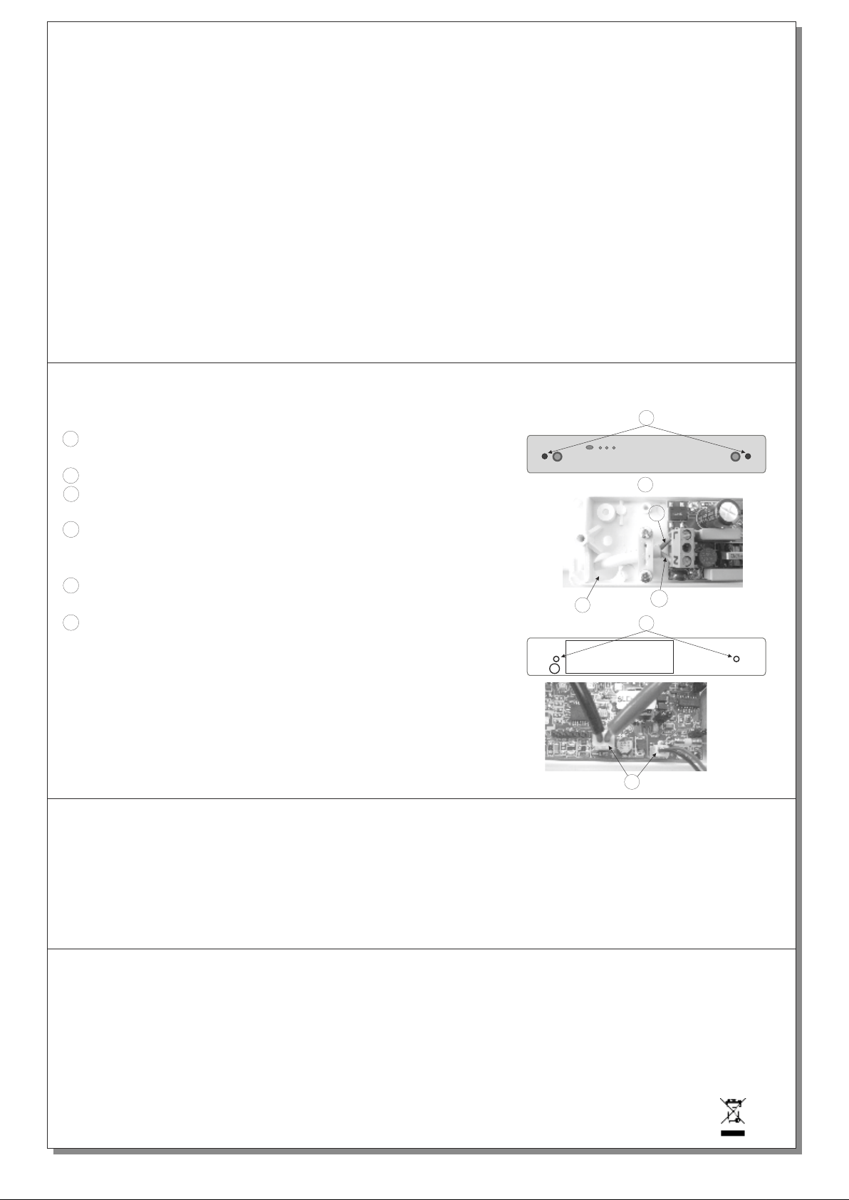
Installation instructions
1
Remove the front plastic cover by unscrewing the two
retaining screws.
2
Pass the mains cables through the hole of the plastic base.
Connect the live and the neutral wires to the terminal block
3
as shown in the picture.
4
Mount the device by installing the included mounting
accessories in the holes or use the Α-3018 mounting
springs for suspended seiling mounting.
Install LED strip and batery connectors to the appropriate
5
PCB connectors.
Refit the front plastic cover by srewing the two
6
removed screws in step 1, and power on the device.
NOTE!!
After finishing the installation you must power the device at least for 24 hours for
battery charging to perform the nominal autonomy.
1
3
L
2
N
4
5
Battery replacement
It can be done only by a competent person and after the mains interruption
1. Follow the step 1 of the installation instructions.
2. Disconnect the connector and remove the old battery.
3. Connect the new battery with the same type (step 5 of the installation instructions) and place it in the position of the old one.
4. Replace the removed parts (step 1) and power the device.
General:
1. Operations for installation, maintainance or testing must be done by authorized personnel only.
2. The device must be connected to the mains power supply through a fuse dependent by the total
amount of the line’s power load.
3.
In case of battery or light source replacement, these must be replaced by parts of the same type,
by the manufacturer or by a competent person.
4. In case of inactive use for a period greater than 2 months, disconnect the battery by pulling out
the battery’s connector.
5. I s not allowed to discard batteries in to common trash bins, they must be
t i
discarded only
in battery recycling points. Do not incinerate.
Page 2 from 4
922044000_09_027
Page 3
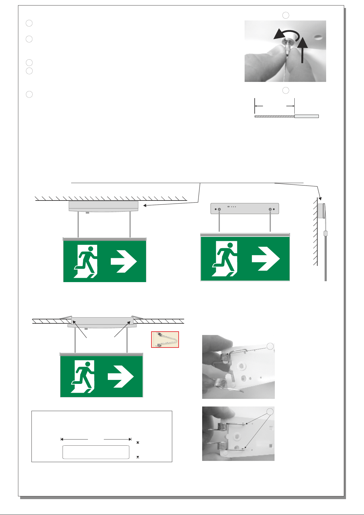
Changing the length of the panel’s cables (initial length 50cm.)
To release the panel’s cables unfasten the screw of the
1
holding system and push forward.
2
Cut the desirable length to shorten the cable and to ensure
the electrical connectivity strip the isolating wrap for
about 2cm from the edge of the panel’s cable.
3
Follow the same steps for the second panels cable.
Enter carefully each panel’s cable, (to adjust the placement
4
of the panel) by pushing forward the screw of the holding
system.
5
After the adjustment of the panel, screw tightly the screws
of the holding systems and power on the mains power suypply .
ATTENTION!!
To disconnect the panel’s cables, you have to power off the mains power supply and
disconnect the battery.
Note: The length of the panel’s cables can reach 1.5m after request.
When the device is mounted externally it can use the A-1028 mounting box.
1
2
2cm
Ceiling mounted installation
A-3018
mounting springs
A-3018
Wall mounted
Placing the mounting springs
Α-3018
1
Place one
part of
the mounting
spring first
and then
the other one.
Recess mounted on suspended ceilings
In recess mounting installation the
required opening is 280 x 50 mm.
The material must withstand the luminaires weight.
280
50
Page 3 from 4
2
Place the
edges of
the mounting
spring as
shown
in the picture.
922044000_09_027
Page 4
NOTE: LED= Light Emitting Diode
LABELING EXPLANATION:
X: Self contained
1: Maintained (*)
A: Including test device
G: Internally illuminated
180: 3 hours duration
(*) Maintained operation: The luminaire lights its illumination source, when it is powered by the mains power supply or not.
Non Maintained operation: The luminaire lights its illumination source, only in power supply’s failure.
The light source contained in this luminaire shall only be replaced by the manufacturer, or his agent, or a similar qualified person.
NOTE! The light source is non-user replaceable.
WARRANTY
Olympia Electronics guarantees the quality, condition and operation of the goods. The period of warranty is specified in the official catalogue of Olympia
Electronics and also in the technical leaflet, which accompanies each product. This warranty ceases to exist if the buyer does not follow the technical
instructions included in official documents given by Olympia Electronics or if the buyer modifies the goods provided or has any repairs or re-setting done
by a third party, unless Olympia Electronics has fully agreed to them in writing. Products that have been damaged can be returned to the premises of our
company for repair or replacement, as long as the warranty period is valid.
Olympia Electronics reserves the right to repair or to replace the returned goods and to or not charge the buyer depending on the reason of defection.
Olympia Electronics reserves the right to charge or not the buyer the transportation cost.
HEAD OFFICE
72nd km. O.N.R. Thessaloniki-Katerini
P.C. 60300 P.O. Box 06 Εginio Pierias Greece
www.olympia-electronics.gr
[email protected]
Manufacturer
Model Number
Voltage Range
Nominal Power
Connections
Temperature (tc)
Page 4 from 4
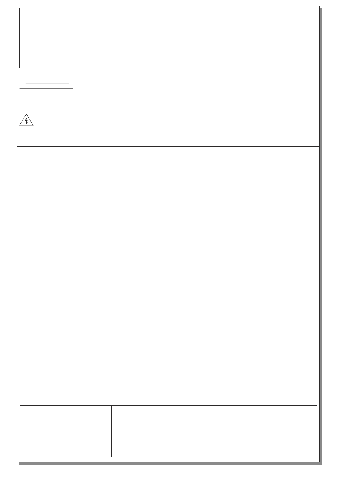
LED MODULE CHARACTERISTICS
SLD-28/DZ
Olympia Electronics S.A.
0106163 1307083
0.78W
Cable connection between main pcb and led module
45 °C max. across the board
SLD-34/DZ
2312083
8.7-10.8V DC
0.975W
SLD-44/DZ
922044000_09_027
 Loading...