

Page 1
High Quality European based Manufacturers
GR-940/15L/MAR WATERPROOF SELF TESTING EMERGENCY LUMINAIRES
TECHNICAL CHARACTERISTICS
OPERATION VOLTAGE
MAXIMUM POWER CONSUMPTION
BATTERY (Ni-Cd)
BATTERY PROTECTION
INDICATIONS
CHARGING TIME
MINIMUM AUTONOMOUS DURATION
ILLUMINATION SOURCE
ILLUMINATION (MAINS / EMERGENCY)
DEGREES OF COVER PROTECTION
PRODUCED IN ACCORDANCE WITH
OPERATION TEMPERATURE RANGE
RELATIVE HUMIDITY
CONSTRUCTION MATERIALS
EXTERNAL DIMENSIONS
TYPICAL WEIGHT
GUARANTEE
EN 6 05 98 -1 , EN 6 05 98 -2 -2 2, Ε Ν 55 01 5, ΕΝ 61 54 7, ΕΝ 61 000- 3-2, Ε Ν 61 000- 3-3, I EC 600 92-3 06, IE C 60 533
Ba yb l en d FR 3010 , tran spar ent po lyca rbon ate
22 0- 2 40 V AC /5 0- 6 0H z
4W /7 VA
From overcharge and full discharge
Charge, lamp fault, battery fault indication LED
3 ye ar s ( 1 ye ar f or the b atte ry)
3. 6V / 3A h
24 h
48 0m i n
15 w hi t e LE D’ s
10 5l m / 1 05 lm
IP 6 5
o
5 to 4 0 C
Up t o 95 %
363 x 145 x 73 mm
94 5g r.
Thank you for purchasing this product of
O ly m p i a E l e c t r o n i c s . A E u r o p e a n
manufacturer.
GENERAL
These luminaires, according to Lloyd’s
Register Type Approval System are
s u i ta b l e f or m a ri n e a n d o ff s ho r e
applica tions for use in e nvi ronmental
categories ENV1, ENV2, ENV3 and ENV4,
where ENV1 are controlled environments,
ENV2 are enclosed spaces subject to
temperature, humidity and vibration, ENV3
are enclosed spaces subject to generated
heat from other equipment and ENV4 are
mount ed on rec ipro cating m achiner y.
Each l uminair e must be permane ntly
connected to mains power supply. In
normal operation the led strip lights and
the battery is charging. In case of a mains
power supply failure the luminaire will light
the led strip automatically in emergency
mode. When the mains power supply is
re s t o r e d the device t u r n s to normal
operation.
INSTALLATION
To install the luminaire follow the
installation instructions on page 3.
OPERATION
Battery Charging
The battery charging is completely
Page 1 from 2
controlled. In this case, is achieved the
perfect battery maintenance , as well as
the elongation of its duration. When the
battery has completely charged, it charges
with a maintenance current.
Battery Cut-off
The luminaire enters in this operation when
the mains power supply fails and battery
has lost its energy. During this operation
the luminaire enters the idle state and
battery consumption is negligible, in order
to be protected from deep discharge.
Manual Test
The manual test can be conducted only if
the main power supply and the battery is
connected. By pressing the TEST/RESET
button briefly (page 3) an operation test is
initiated. During this test period all
indication LEDs are OFF.
Automatic Test
This test includes all the operations that
provide the manual test and is conducted
automatically every 15 days. In order to be
performed, the main power supply and the
battery should be connected.
Automatic Autonomous Test
The Automatic Autonomous Test is
conducted and measures the luminaire`s
back up operation. This test is conducted
automatically every six months. In order to
be performed, the main power supply and
923940002_09_003
Page 2

the battery should be connected (the
battery should be charged). If the battery
is not charged, the test is postponed until
the battery is completely charged. If during
the Automatic Au t o n o m o u s Test th e
luminaire’s duration is lower than the
no m i nal , th en t h e b att e ry mus t be
replaced.
Back Up Operation
The autonomous duration of battery during
emergency mode is at least the one that is
stated in the technical characteristics.
During emergency mode, a LED strip test
is also performed.
Resetting Errors
Push the TEST/RESET button for 5
seconds, to extinguish all the indicated
LED errors (page 3). Then the luminaire
enters regular operation mode.
Indication LED status
(with connected mains power supply).
Charge
On: Good charge current.
Οff: No battery (No charging current or
disconnected battery).
Lamp Fault
Οn: Faulty LED strip.
Off: Good LED strip.
Battery Fault
Οff: Battery OK.
Blink (With Charge LED ON): Autonomy
or low battery problem
(the battery must be replaced).
Blink (With Charge LED Off):
No charging current or disconnected
battery.
5. I s not allowed to discard batteries in t i
to common trash bins, they must be
discarded only in battery recycling
points. Do not incinerate.
NOTE: LED= Light Emitting Diode
LABELING EXPLANATION:
X: Self contained
1: Maintained (*)
A: Including test device
480: 8 hour duration
(*) Maintained operation: The luminaire
lights its illumination source, when it is
powered by the mains power supply or not.
Non Maintained operation: The luminaire
lights its illumination source, only in power
supply’s failure.
NOTE!! After finishing the installation
you must power the luminaire at least
for 24 hours for battery charging to
perform the nominal autonomy.
Battery replacement
1. Unfasten the 4 retaining screws (step 10
of the installation instructions) and remove
the diffusor.
2. Unfasten the 2 retaining screws step 9 of
the installation instructions and remove the
reflector.
3. Remove the old battery and place a new
on of the same type and characteristics.
4. Replace the removed parts (previous
steps 1,2).
ΑΤΤΕΝΤΙΟΝ!!!
1. Operations for installation, maintainance
or testing must be done by authorized
personel only.
2. The device must be connected to the
main s p o w e r s u p p l y t h r o u gh a fuse
dependent by the total amount of the line’s
power load.
3. In case of battery or lamp replacement,
these must be replaced by parts of the
same type, by the manufacturer or by a
competent person.
4. In case of inactive use for a period
greater than 2 months, disconnect the
batte r y b y p u ll i ng o ut t he b at t er y ’s
connector.
Page 2 from 3
923940002_09_003
Page 3
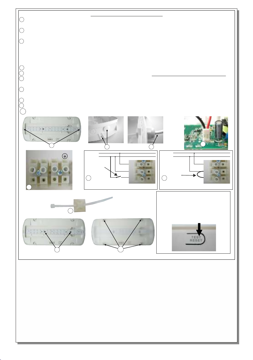
1 Remove the diffusor. Place simultaneously 2 flat blade screwdrivers and pull up gently the
INSTALLATION INSTRUCTIONS
reflector.
2 Install the included plastic cover in to the unused hole and install the base plastic (with the
included mounting screws and plugs).
3 Always use in any case round mains cable, with external diameter of 6-9mm (H05RN-F
type 2x1mm² or any other type, at least equal to it’s mechanical and electrical properties).
ATTENTION!! The cable must not be deformed in any way (This requirement is important
to ensure the tightness isolation IP 65). Install the cable gland, pass the round cable through
and tighten it all the way.
4 Place the battery’s connector to the corresponding connector on the P.C.B.
5 Connect the mains cables to the respective terminal block (connect the ground wire if required).
6 Ν for neutral, L for live wire and L1 for the maintained operation. The L1 wire can be connected
to an external switch to control the maintained or non maintained operation of the luminaire.
7 For permanent maintained operation use two wires to power the luminaire, Ν for neutral and L for
live wire, and link the L and L1.
8 Install the included tie (if needed) to fasten securely the power cables.
9 Refit the reflector and fasten the two small screws (included).
10 Finaly place the diffusor by using the 4 included screws (tightening torque 1.2 Nm).
L1 L N
5
1
N
L
External
switch
2
6
Controlled operation of the lamp
8
9
10
3
N
L
Link
L1 L N
7
Permanent maintained operation
Manual TEST or Resetting Errors
In order to test or reset the device you
must carefully remove the diffusor by
unfastening the 4 mounting screws.
Then push the button as described in
the according paragraphs on page 1.
4
L1 L N
Page 3 from 3
923940002_09_003
 Loading...