

Page 1

High Quality European based Manufacturers
GR-24/12-1
STABILIZED POWER SUPPLY 12V DC
TECHNICAL CHARACTERISTICS
OPERATION VOLTAGE
MAXIMUM POWER CONSUMPTION
SEALED LEAD ACID BATTERIES (Pb)
OUTPUT
BATTERY PROTECTION
INDICATIONS LED’s
CHARGING TIME
AUTONOMY (with maximum Load)
REMOTE INPUT VOLTAGE RANGE
DEGREES OF COVER PROTECTION
PRODUCED IN ACCORDANCE WITH
OPERATION TEMPERATURE RANGE
RELATIVE HUMIDITY
CONSTRUCTION MATERIALS
EXTERNAL DIMENSIONS
TYPICAL WEIGHT
GUARANTEE
Thank you for purchasing this product of
Oly m pia E l ect r oni c s. A Eur o pea n
manufacturer.
GENERAL
The GR-24/12-1 is a stabilized power supply
continuous operation that provides a voltage of
12V DC to independent devices (according to
the device). The output network is stabilized to
the 13,5 V DC with a maximum current 4Α.
It provides continuous power to the external
devices, with the incorporated power supply as
long as the mains power supply does not fail.
In case of mains failure the device gives power
to the external devices from the included
battery.
In fire detection systems it is used when the
detector’s power consumption is greater than
the maximum panel that the panel can provide.
It is also used to power any other device that
require 12 V DC and autonomous operation.
The device includes the SW1 switch which
activates or deactivates the output as long as
you desire.
The green indication LED indicates the output
status. The jumper LOCAL/REMOTE is also
used according to the input REMOTE in the
respective terminal blocks and concerns the
output status. If no external device to control
the GR-24/24-1 output is connected then the
jumper must be placed in pins 1-2 and the
output control can be done with the switch
SW1. If you want to control the output from an
external device,
then the jumper must be placed in pins 2-3,
85-265V AC/50-60Hz
163 VA
Network: 13.5V/ 4A (max.) / Battery : 12V / 4 A (max.)
Mains/battery charging red LED, output activation green LED
EN 55015, EN 61547, EN 60950-1, EN 61000-3-2, EN 61000-3-3
Bayblend FR3010, transparent polycarbonate
2x12V/7Ah (not included)
From overcharge and full discharge
24 h
6-30V DC / 1.5mA (maximum)
3 years (1 year for the battery)
3 h
IP 42
o
0 to 40 C
Up to 95%
300 x 95 x 230 mm
5150gr.
the switch SW1 in the ON position and the
control signal must be connected to the
REMOTE terminal blocks. In the input, when
the voltage exceeds 6V, then the GR-24/12-1
output is active and when the voltage remains
under 6V the output remains deactivated.
Autonomy calculation example
The autonomy of the device is proportional to
the battery (i.e 7Ah for GR-24/12-1 and
inversely proportional to the consumption of
the number of detectors. If you want to connect
10 devices that consume 200mA from the GR24/12 -1, then th e autonomy will be
approximately 6 hours, and if we want to
connect 20 devices, the autonomy will be
approximately 3 hours. In this way we can
calculate how many detectors will connect to
the power supply and how much autonomy we
have. The device has an electronic fuse that
protects its output from short circuits that could
cause serious problems.
When activated the
electronic safety output is disconnected
permanently and for restoring the functioning of
the device will be restored in a shortcircuit and
to disconnect the network and the battery for a
few seconds.Immediately after can function
normally.
ΑΤΤΕΝΤΙΟΝ!!!
1. Operations for installation, maintainance or
testing must be done by authorized personel
only.
2. The device must be connected to the mains
power supply thru a fuse dependent by the
total amount of the line’s power load.
923024005_23_006Page 1 from 2
Page 2
t i
3. I s not allowed to discard batteries in to
common trash bins, they must be
discarded only
in battery recycling
points. Do not incinerate.
INSTALLATION
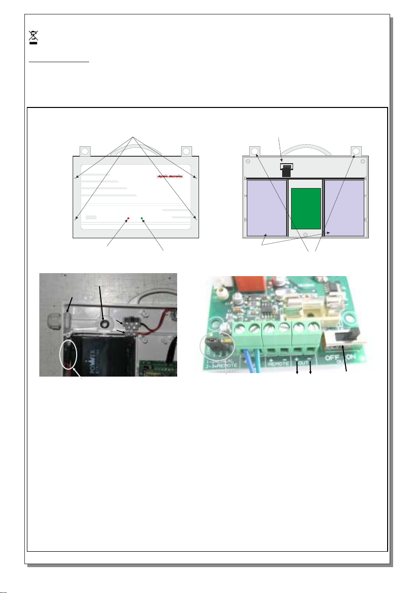
To install the device follow the installation
instructions bellow.
Battery replacement.
It can be done only by a competent person and
INSTALLATION INSTRUCTIONS
1
OUTPOWER
after the mains interruption.
1. Follow the step 1 of the installation
procedure. 2. Disconnect the cables and
remove the old battery. 3. Connect the new
battery with the same type (step 7 of the
installation procedure) and place it in the
position of the old one. 4. Follow the step 8 of
the installation procedure and power the
device.
Mains connection terminal block
Mains/battery charge
indication
Output activation
indication
Battery
4
3
2
L
N
7
1. Remove plastic cover by unscrewing the mounting screws.
2. Install the cable gland to pass the output cables.
3. With a drill (11mm) open a hole and place the included rubber ring to pass the mains cables. Pass
the mains cables and connect them to the L terminal block for live wire and to the Ν for neutral.
4. Install the included mounting accessories and hook the device from the mounting holes.
5. Pass the output cables thru the cable gland and connect them to the +OUT- terminal blocks
(respect the polarity). Attention!!! The output cables must have a diameter of 2,5mm minimum.
6. Make sure that the switch in the ON position and the jumper is placed on pins 1-2 .
7. Connect each cable terminal to the battery’s pole (red cable to (+) pole and black cable to (-)
pole). Place each battery in the respective area of the base plastic.
8. Refit the front plastic cover and mount it with the removed screws in step 1.
9. The device is ready to be activated.
NOTE!!
After finishing the installation you must power the device at least for 24 hours for battery charging
to perform the named autonomy.
front
6
5 6
Page 2 from 2
923024005_23_006
 Loading...