

Page 1
SELF TESTING NON-MAINTAINED EMERGENCY CEILING MOUNTED LUMINAIRES
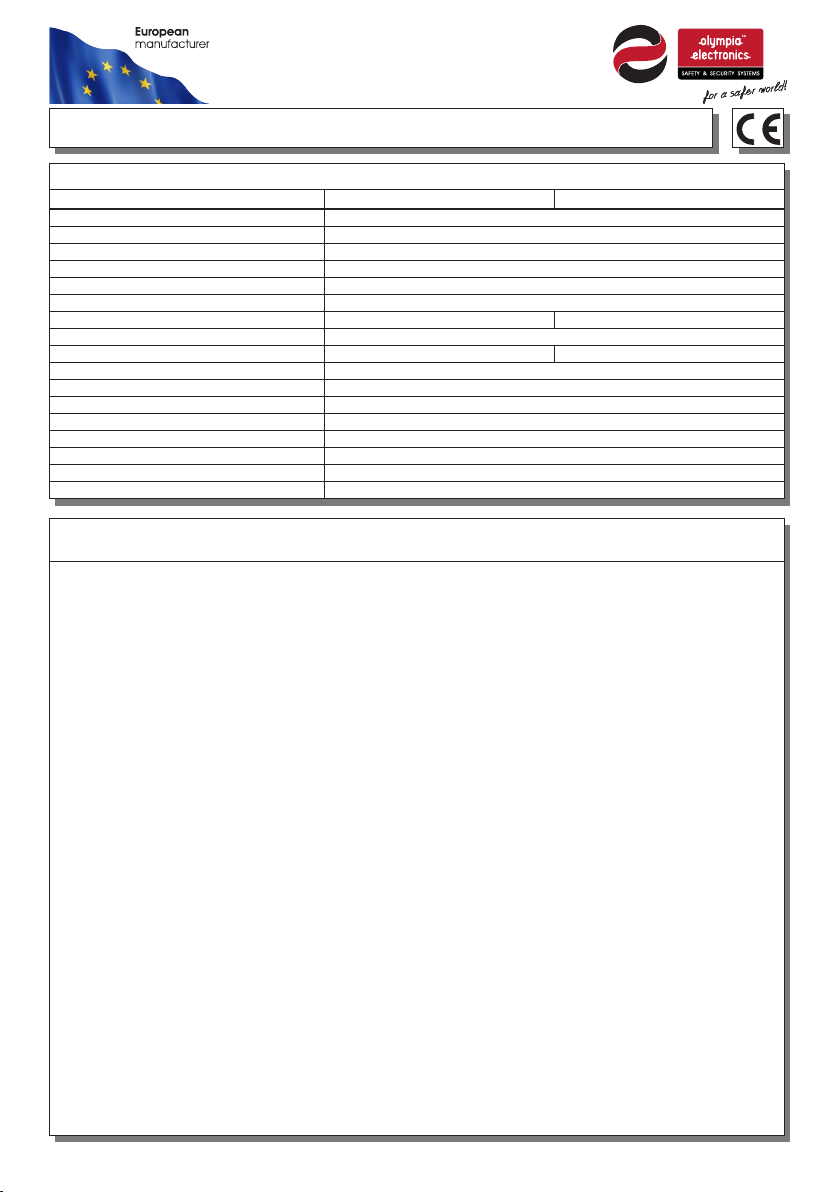
TECHNICAL CHARACTERISTICS (for LED MODULE specifications see page 5)
OPERATION VOLTAGE
MA XI M UM P O WE R C ON S UM PTI ON
BATTERY (NiMh)
BATTERY PROTECTION
INDICATIONS - CONTROLS
CHARGE TIME
MI NI M UM D U RAT I ON
LIGHT SOURCE
EMERGENCY ILLUMINATION
DE GR EES OF C O VE R P RO T EC T IO N
PRODUCED IN ACCORDANCE WITH
OP ER AT IO N TEM PE RATUR E R AN G E
RELATIVE HUMIDITY
CONSTRUCTION MATERIAL
EX TE R NA L DI M EN S IO N
WE IG H T
GU AR A NT E E
Thank you for your trust in our products
Olympia Electronics - European manufacturer
GENERAL
This device is used indoors (ta 40 C) in
places where emergency luminaires are
needed. The luminaire has pre-installed the
anti panic lens. The package also contains
the corridor lens that can be replaced by the
user. Each device must be permanently
connected to mains power supply. In normal
operation the battery is charging. In case of
a mains power supply failure, the device
enters emergency mode and the illumination
LED turns on. When the mains power
supply is restored the device turns to normal
operation.
INSTALLATION
To install the luminaire follow the installation
instructions οn page 3.
Battery Charging
The battery charging is completely
controlled. In this case, is achieved the
perfect battery maintenance , as well as the
elongation of its duration. When the battery
has completely charged, it charges with a
maintenance current.
Battery Cut-off
The device in this operation when the mains
power supply fails and battery has lost its
energy. During this operation the device
Page 1 from 6
GR-220/DUO/M
22 0- 240V A C / 50-6 0Hz
4. 3W / 4 . 7 VA
De ep d isch arge a nd ove rcha rge pr otec tion
Charge, lamp fault, battery fault, TEST button
1. 5 ho u r
30 0l m
EN 6 05 98 -1, EN 6 0598 -2-2 2, ΕΝ 55 015, Ε Ν 6154 7, ΕΝ 61 000- 3-2, Ε Ν 6100 0-3- 3
o
enters the idle state and battery consumption
is negligible, in order to be protected from
4. 8V / 1. 2 Ah
24 h ou rs
1 wh it e p ow e r LE D
IP 40
o
5 to 4 0 C
Up t o 95 %
AB S/ P C
Ø125 x 62 mm
3 ye ar s ( 1 y ea r f or t h e ba tte ry)
47 4g r.
deep discharge.
Manual Test
This test can be done by pushing the test
button. The light source and the emergency
circuit of the device is monitored. The manual
test can be conducted only if the main power
supply and the battery is connected. During
this test period all indication LEDs are OFF.
Automatic Operational Test
This test includes all the operations that
provide the manual test and is conducted
automatically every 15 days. In order to be
performed, the mains power supply and the
battery should be connected.
Automatic Autonomous Test
The Automatic Autonomous Test is conducted
and measures the device’s back up operation
and emergency duration. The BATTERY
FAULT LED blinks during the measurement,
indicating this process to the user. This test is
conducted automatically every six months. In
order to be performed, the mains power
supply and the battery should be connected
and fully charged. If the battery is not fully
charged, the test is postponed until the
battery is completely charged. If during this
test, the autonomy is less than the nominal
GR-221/DUO/M
3 ho ur s
15 0l m
923221000_09_001
Page 2
then the battery fault led turned on
continuously and the battery must be
replaced.
Back Up Operation
The autonomous duration of battery during
emergency mode is at least the one that is
stated in the list of the technical
characteristics. During emergency mode, a
light source test is also performed.
Resetting Errors
Push the Test button for >10 seconds, to
delete all the indicated LED errors. Then the
device enters regular operation mode.
Test Switch
Pressing the test switch less than 5 seconds
will initiate a light source test (last for 3 secs).
If the test switch is pressed for more than 10
seconds, the device will be reset (delete all
errors).
ΑΤΤΕΝΤΙΟΝ!!!
1. Operations for installation, maintainance or
testing must be done by authorized personnel
only.
2. The device must be connected to the
m a i n s p o w er s u pp l y th r ou g h a f us e
dependent by the total amount of the line’s
power load.
3. The replacement of the battery and the light
source must be done using parts of the same
type, by the manufacturer or by a competent
person.
4. In case of inactive use for a period greater
than 2 months, disconnect the battery by
pulling out the battery’s connector.
5. I s not allowed to discard batteries into t i
common trash bins, they must be
discarded only in battery recycling
points. Do not incinerate.
Connection to module (After request)
This luminaire can be connected to any of the
following modules: Remote module, address
module, wireless module and fault relay
module. If you connect it to a module that
supports inhibit or rest mode, you should
know that these commands can be cancelled
only during normal mode (ie. not in
emergency). For installation refer to step 3 of
the istallation procedure in page 3.
Also refer to the user’s manual of each
module for additional information.
NOTE: LED= Light Emitting Diode
LABELING EXPLANATION:
X: Self contained
0: Non maintained (*)
A: Including test device
E: With non-replaceable lamp(s)
F: Automatic test gear complying with IEC
61347-2-7 denoted EL-T
90: 1.5 hour duration
180: 3 hour duration
(*) Non Maintained operation: The luminaire
turns on illumination source, only in case of
power supply failure.
Note!! If a module will be used (except the fault
relay module), then the installer should fill in, on
the specification label, the letters B C.
X 0 9 0A E F
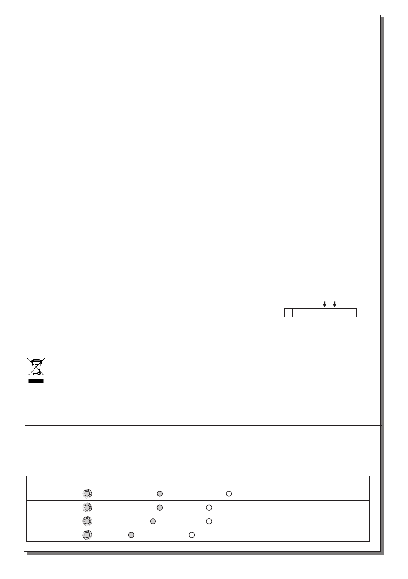
Status of LEDs
LEDs Description of indication
CHARGE : Battery charging, : battery charged, : disconnected or unfunctional battery
LAMP FAULT : Operation check, : lamp fault, : normal operation
BATT. FAULT : Autonomy test, : battery fault, : normal operation
Page 2 from 6
923221000_09_001
Page 3
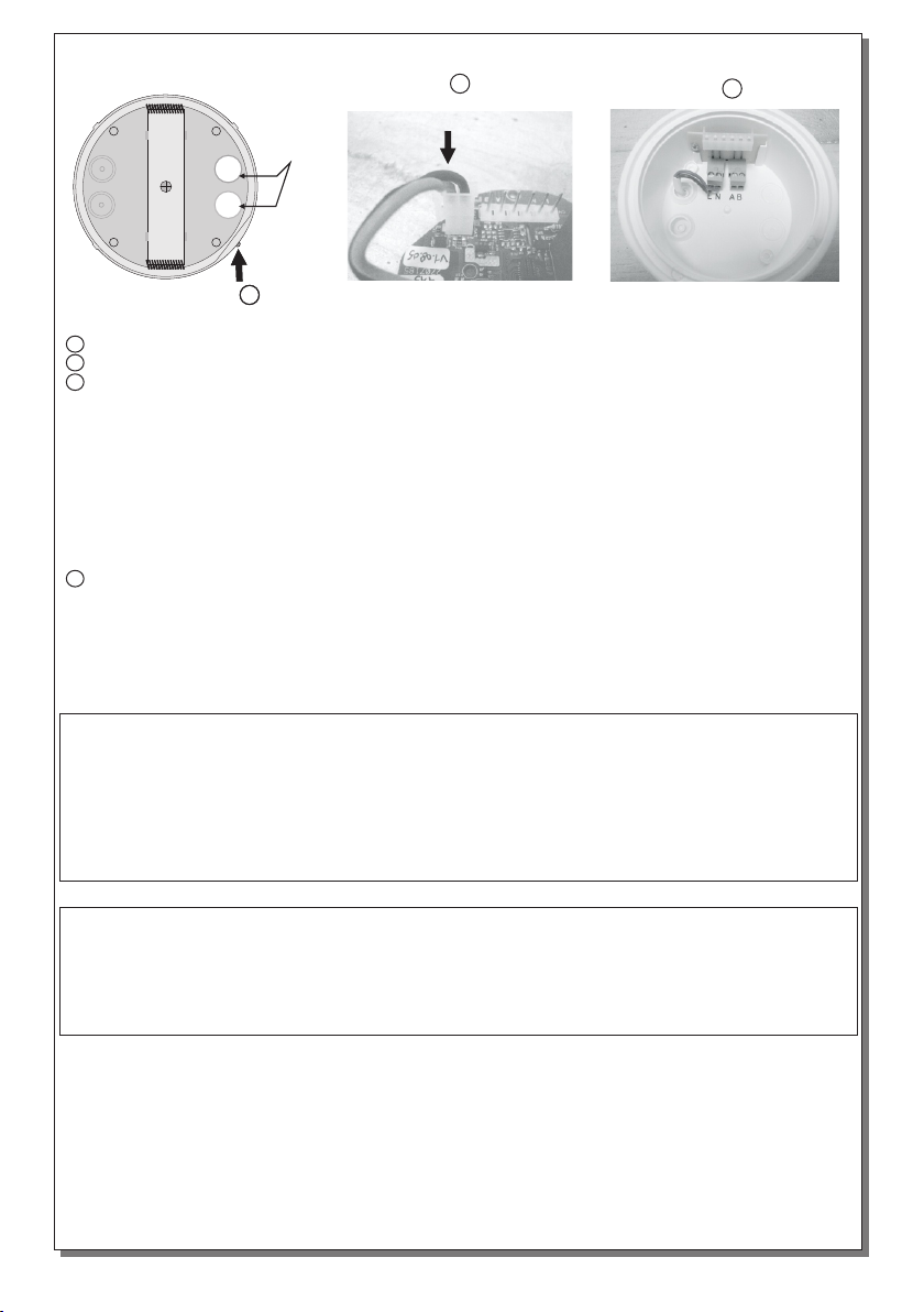
INSTALLATION INSTRUCTIONS
2
Cable
entry
holes
11
Initial installation
1 Untighten the screw but do not remove it and pull up the reflector.
2 Place the battery’s connector to the corresponding connector on the P.C.B.
3 Always use in any case round mains cable, with a diameter of 5-10mm (H05RN-F
type 2x1mm² or any other type, at least equal to it’s mechanical and electrical properties).
ATTENTION!! The cable must not be deformed in any way (This requirement is important
to ensure the ΙΡ rating). Install the included gaskets in to the cable entry holes (verify that are
not deformed). Make a hole in the center by using a small screwdriver. Pass the round cable
through the gasket. Detach the power terminal, connect the wires as shown in the picture and
attach the power terminal (10A max). If you use a module pass the 2 signal cables on the A, B
terminals Minding the correct polarity. Depending on the module that will be used, the cables that
will be used, have different names. In A, signal +L, C are also connected, while signals -L,
NC/NO in the terminal B.
4 Refit the reflector (mind the correct orientation), tighten the screw securely and the luminaire
is ready for mounting.
NOTE!! After finishing the installation you must power the luminaire for at least 24 hours in
order to completely charge the battery. The rated autonomy duration can be achieved after
that time.
3
Battery replacement.
It can be done only by a competent person and after the mains interruption.
1. Remove the luminaire from the suspended ceiling (figure 3).
2. Follow the step 1 of the installation instructions.
3. Disconnect the connector and remove the old battery.
4. Connect the new battery with the same type (step 2 of the installation instructions) and place it in
the position of the old one.
5. Replace the removed parts (step 1 and 4) and power the device.
Important notice for the installed luminaires in one area !!!
The installer must connect the battery’s connector first and then should power the luminaire.
The time between batteries connection must be, at least 1.5 minute.
With this variation, it is ensured that the non synchronized Automatic Autonomous Test for two or more
luminaires installed in one area, is not conducted in the same day.
Page 3 from 6
923221000_09_001
Page 4
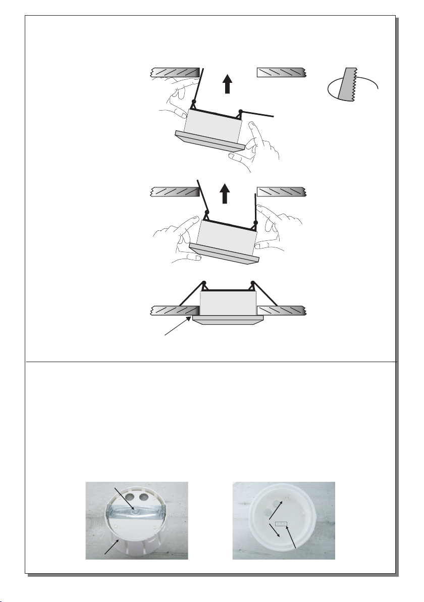
Mounting the lamp in suspended ceiling.
Set up the lamp to the suspended ceiling as it is shown bellow (Required opening 110mm):
Step 1
Bend the springs, to get into the hole of the suspended ceiling, as you can see to the next figure.
Figure 1
Ø110mm
Step 2
Push up the luminaire, as shown in figure 2.
Figure 2
Step 3
Continue to push upwards until the lamp locks.
Figure 3
If you want to pull off the device, put a flat blade
screwdriver, between the device and the ceiling.
Surface mounting.
Install the luminaire according to the following steps:
Step 1. Follow the step 1 of the installation instructions.
Step 2. Unfasten the retaining screw (Photo 1) and detach the part for suspended ceiling
installation.
Step 3. Drill 2 holes on the base using a 4mm drill bit in order to permit the retaining screws to pass.
Mark these two drilled points on the required mounting location, drill the holes and install the
supplied plastic plugs. ATTENTION!! When using the corridor lens ensure the correct orientation of
the light direction as shown on the luminaire’s base (Photo 2).
Step 4. Install the decorative rim (package included) as shown on photo 1. Next, use the 2 fasteners
to install the unit to the require location.
Step 5. Follow the steps 2,3 and 4 of the installation instructions.
Retaining fastener
Drill here
Decorative Rim
Photo 1
Page 4 from 6
Indications
Photo 2
923221000_09_001
Page 5
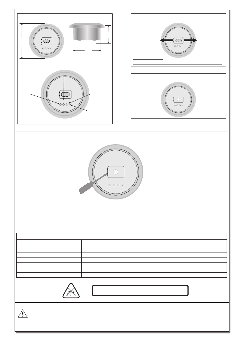
GR-220/DUO/M
125
Battery
charge
indication
LED
Figure 4
LAMP
BATT.
CHARGE
TEST
FAULT
Lamp fault
indication LED
62
96
Battery
fault
indication
LED
LAMP
BATT.
CHARGE
TEST
FAULT
Test
button
Corridor
lighting
LAMP
BATT.
CHARGE
TEST
FAULT
ATTENTION!!!
During installation follow this light direction.
GR-220/DUO/M
Open
area
lighting
LAMP
BATT.
CHARGE
TEST
FAULT
LENS REPLACEMENT
LAMP
BATT.
CHARGE
1. To replace the lens , first be sure that the luminaire in not connected in the mains power supply
and the battery is not connected.
2. Use a flatblade screwdriver to pry open the lens retaining cover.
3. Remove the placed lens and insert the newone taking care the two alignment pins on the lens are
inserted in the holes on the PCB. Be carefull not to touch the LED with your hand.
TEST
FAULT
LE D M O D U L E C H A R A C T E R I S T I C S
GR-220/DUO/M GR-221/DUO/M
Ma nuf a ctu r er
Mo del N u mbe r
Vol t age R a ng e
No min a l Pow e r
Co nne c tio n s
fi xed c o nne c tio n bet w een m a in pc b and l e d mod u le
Tempe rat u re (t c )
CAUTION : Do not view directly with bare eyes
The light source contained in this luminaire shall only be replaced by the manufacturer, or his
agent, or a similar qualified person.
NOTE! The light source is non-user replaceable.
Page 5 from 6
Ol ymp i a Ele c tro nic s S .A.
06 061 8 5
3- 3,2 V D C
1, 3W
6 °0 C m ax. a c ros s t he b o ard
923221000_09_001
Page 6

WARRANTY
Olympia Electronics guarantees the quality, condition and operation of the goods. The period of
warranty is specified in the official catalogue of Olympia Electronics and also in the technical leaflet,
which accompanies each product. This warranty ceases to exist if the buyer does not follow the
technical instructions included in official documents given by Olympia Electronics or if the buyer
modifies the goods provided or has any repairs or re-setting done by a third party, unless Olympia
Electronics has fully agreed to them in writing. Products that have been damaged can be returned to
the premises of our company for repair or replacement, as long as the warranty period is valid.
Olympia Electronics reserves the right to repair or to replace the returned goods and to or not charge
the buyer depending on the reason of defection. Olympia Electronics reserves the right to charge or
not the buyer the transportation cost.
HEAD OFFICE
72nd km. O.N.R. Thessaloniki-Katerini
P.C. 60300 P.O. Box 06 Εginio Pierias Greece
www.olympia-electronics.gr
[email protected]
Page 6 from 6
923221000_09_001
 Loading...