

Page 1
www.olympia-electronics.gr
S A A R R T C E
CERTIFICATE
VALID SYSTEM
EN ISO 9001 : 2008
Page 2
CONTENTS
1. INTRODUCTION
2. PART TYPES
3. COMPOSING A COMPLETE SYSTEM.
3.1. Systems up-to 48 zones-rooms.
3.2. Systems from 49 to 240 zones -rooms.
3.3. System with many keyboards (repeaters).
4 DESCRIPTION OF KEYS AND INDICATIONS.
5. ACCESS CODES
6. PROGRAMMING
6.1. PRO. Rooms - Zones programming.
6.2. SETUP. Option settings
6.2.1 Address
6.2.2. CLr?.
6.2.3. buzz
6.2.4. UCod.
6.2.5. Ccod
6.2.6. UsuP
6.2.7. dLoA
6.2.8. r-AL
6.3 TEST
7. SIGNAL NUMERATOR PANEL OPERATION MODE (OPERATING).
7.1. Start position operation.
7.2. Calling from one call point.
7.3. Calling from more than one call points.
7.4. Resetting indications - calls.
7.5. Resetting all the calls with a code.
7.6. Viewing the communication faults and the software version of
the keyboard.
7.7. Fault indication signals.
8 PRESENCE OPERATION MODE.
9. USEFUL INSTRUCTION FOR FAST AND EASY MOUNTING.
Instruction flow chart for fast and easy installations.
Page 2 from 18
921746000_09_003
Page 3
Page 3 from 18
1. INTRODUCTION
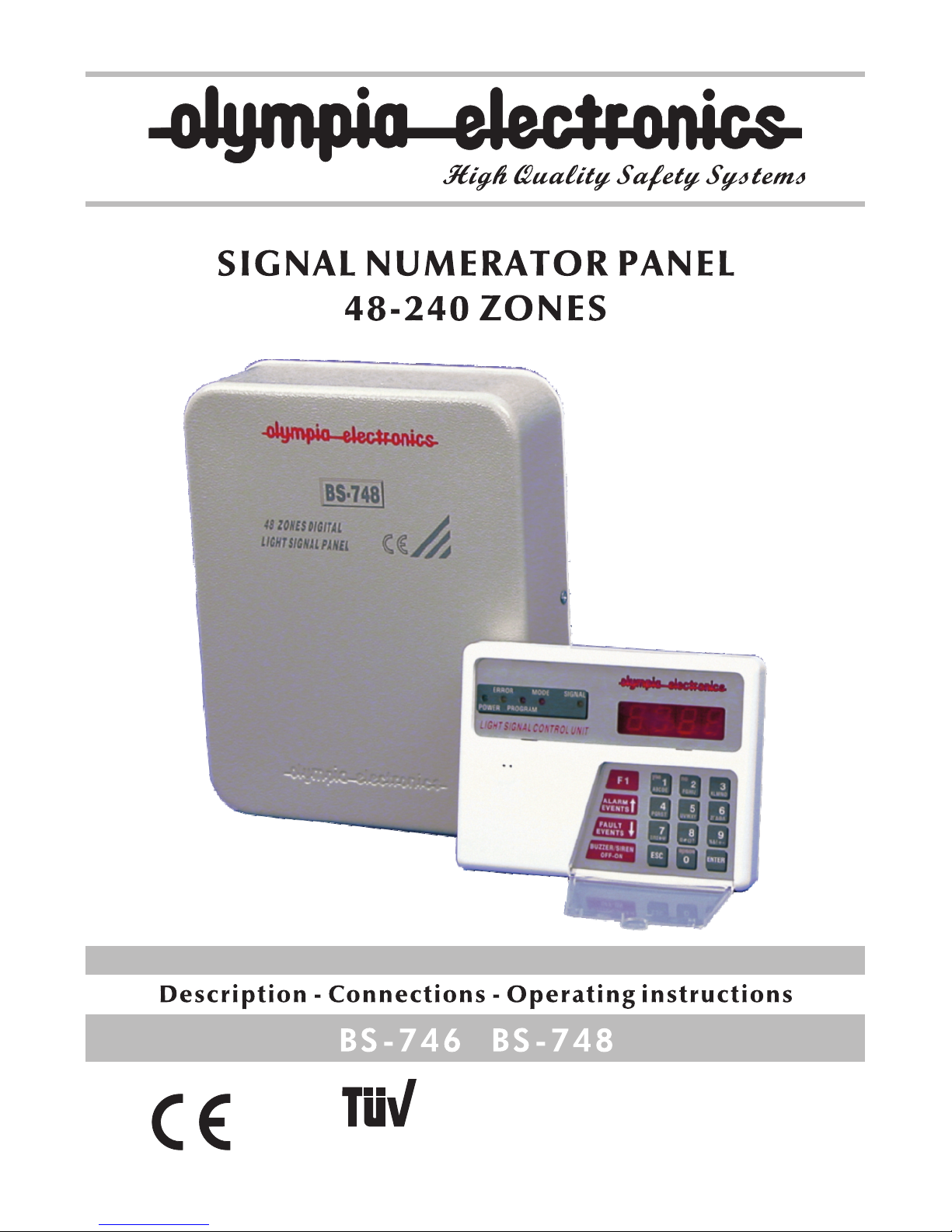
The BS-746 control keyboard cooperates only with the BS-748 panel and composes a
complete signal numerator panel. The device is used mainly for hotel installations.
Usually the BS-748 main panel is mounted in a place which is not visible (e.g. store,
cupboard) and BS-746 control keyboard is mounted in a place which is visible and has
easy access (e.g. RECEPTION). When a call is issued the the display on the keyboard
shows us the room number that issued the call.
2. PARTS TYPES.
BS-748: DIGITAL SIGNAL NUMERATOR PANEL WITH 48 ZONES
BS-746: CONTROL KEYBOARD UNIT OF SIGNAL NUMERATOR PANEL
3. COMPOSING A COMPLETE SYSTEM
3.1. Systems up-to 48 zones - rooms.
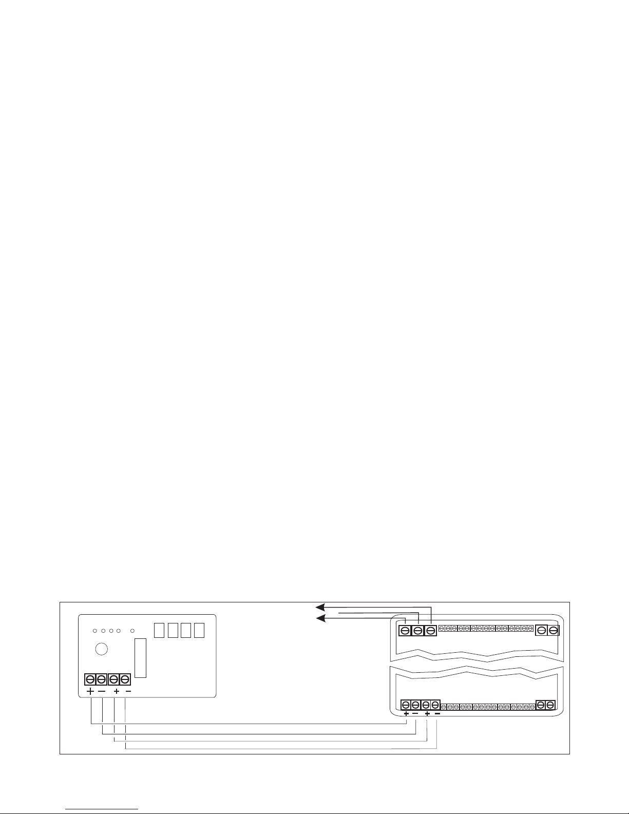
To monitor 48 zones - rooms we must use a BS-746 keyboard and a BS-748
panel(48 zones)These 2 devices are connected to each other with four 4 wires
(fig.1)
3.2. Systems from 49 to 240 zones - rooms.
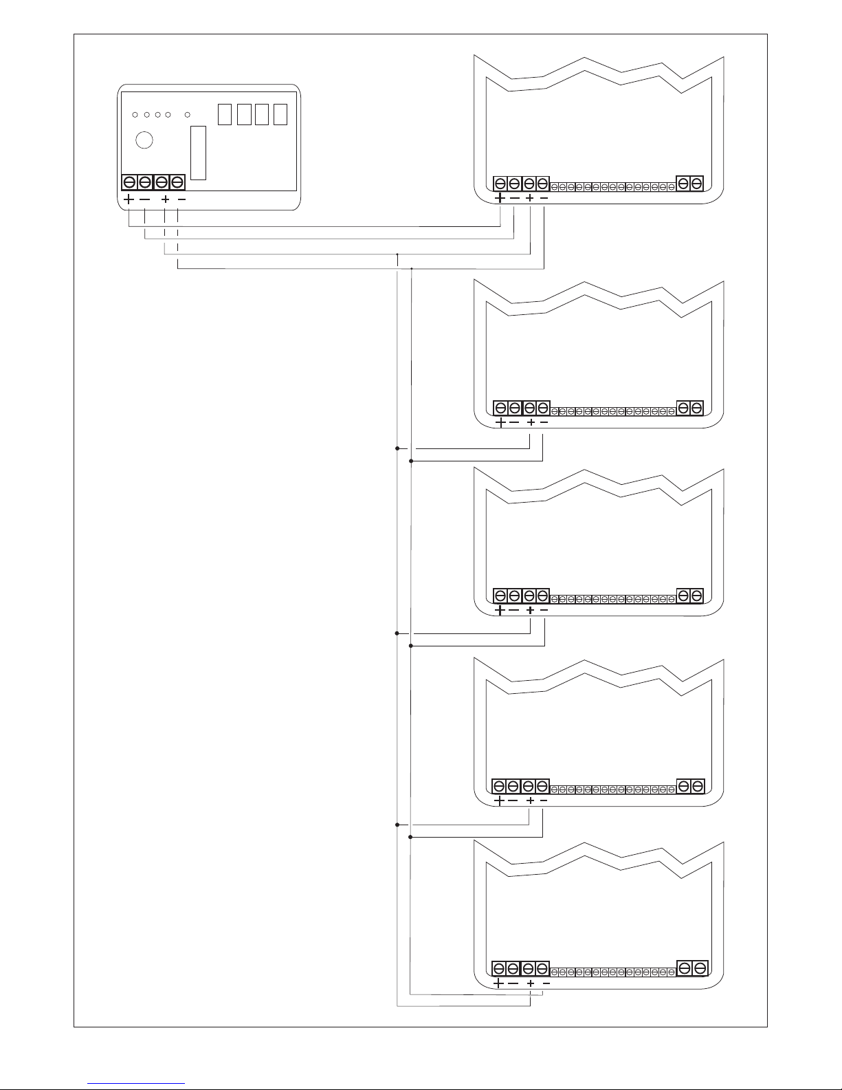
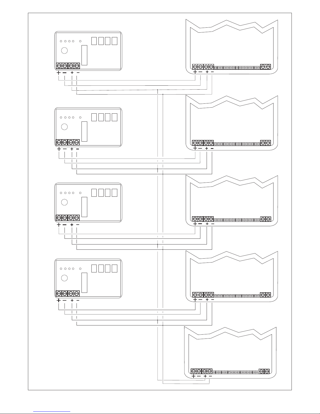
If we want to expand the zones - rooms from 49 to 240 we have to increase the
number of the panels according to the zones - rooms that we want to cover. For each
48 zones we must use an extra BS-748 panel. Every panel has a different address.
The connection diagram is shown in figure 2.
3.3. System with many keyboards (repeaters).
In many cases it is needed to have a system with many keyboards. For this reason
there are the keyboards - repeaters. Every repeater has a different address. The
connections for this type of system are shown in figure 3.
A
BS- 746
Fig1. 48 zones system
BS-746 & BS-748 connections
A
BS-74 8
230 V AC
230VAC
mains voltage
A
A
921746000_09_003
Page 4
Page 4 from 18
BS-74 8 ( master)
BS-74 8 ( slave)
BS-74 8 ( slave)
BS-74 8 ( slave)
BS-74 8 (slave)
BS-746
addre ss 5
addre ss 6
addre ss 7
addre ss 8
addre ss 9
AA
AA
A
A
A A
A
A
A
A
Fig 2.
Con nec tio ns sh ema tic d iag ram
wit h one k eyb oar d BS- 746 a nd 5
pan els B S-7 48
sig nal n ume rat or pa nel 4 8-2 40
zon es
921746000_09_003
Page 5
BS-74 8 (maste r)
A
BS-74 6
(mast er )
addre ss 1
addre ss 5
BS-74 8 (slave)
addre ss 6
BS-7 48 (sl ave)
A
A
addr ess 7
BS-7 48 (sl ave)
addr ess 8
BS-7 48 (sla ve)
addr ess 9
Fig 3.
Con nection diagr am wi th4 k eyb oar ds
BS- 746 and 5 panels BS -74 8 for a
com plete enumera tor p ane l sys tem .
BS-74 6
(slav e)
addre ss 2
BS-74 6
(slav e)
addre ss 3
BS-74 6
(slav e)
addre ss 4
A
A
A
A
A
A A
A
A
A A
A
A
A A
Page 5 from 18
921746000_09_003
Page 6
F1
HELP
ON - OFF
BUZZER
ALARM
EVENTS
FA ULT
EVENTS
ESC
AB CD E FGH IJ KL MN O
PQ RS T UV WX Y ZÃ ÄÈ Ë
ÎÐ ÓÖ Ø Ù #( )? %& !+ -
space
ENTER
21
5
4
87
0
3
6
9
yes no
PR OGRAM
MO DE S IGN ALER ROR
PO WER
LIG HT SIGNAL CONT ROL UNIT
OL-E
1
2
3
4
5
6
7
8
9
10
11
12
Page 6 from 18
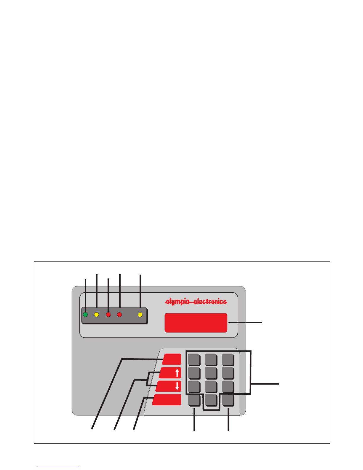
Fig.4 Keys and indications
4. KEYBOARD DESCRIPTION.
KEYS
4.1. The numeric keys 1, 2, 3, 4, 5, 6, 7, 8, 9, 0 are used to enter numbers.
4.2. The ESC key is used for cancelling and operation or exiting a menu.
4.3. The ENTER key is used to confirm an operation.
4.4. The F1 key show us the faults of the communications (if there are any) and
the keyboard software version.
4.5. The Up and Down arrow keys (ALARM EVENTS & FAULT EVENTS) show
us the inputs which have been activated . Also with these keys we can scroll
through the menus.
4.6. The ON-OFF BUZZER, HELP key is used to eliminate/reset individual calls.
INDICATORS
4.7. The POWER LED is lighted when the panel is supplied with 230V AC.
4.8. The ERROR LED is lighted when there is fault in the communications.
4.9. The PROGRAM LED is lighted when we are programming the panel.
4.10.The MODE LED is lighted when the system is in presence operation
mode.
4.11.The SIGNAL LED is lighted when the panel has accepted more than one
signals.
4.12. The LED Display shows the number of the room -zone that issued the
call. It is also used to display the menus used for programming.
921746000_09_003
Page 7

Page 7 from 18
5. ACCESS CODES
User code (0000). Using this code we can reset all calls accepted by the panel. The
default value is (0000)
Technical code (1111). Using this code we can access the programming menu. The
default value is (1111)
Reset code (9946). Using this code we can reset the user and the technical codes to
their default values.
6. PROGRAMMING
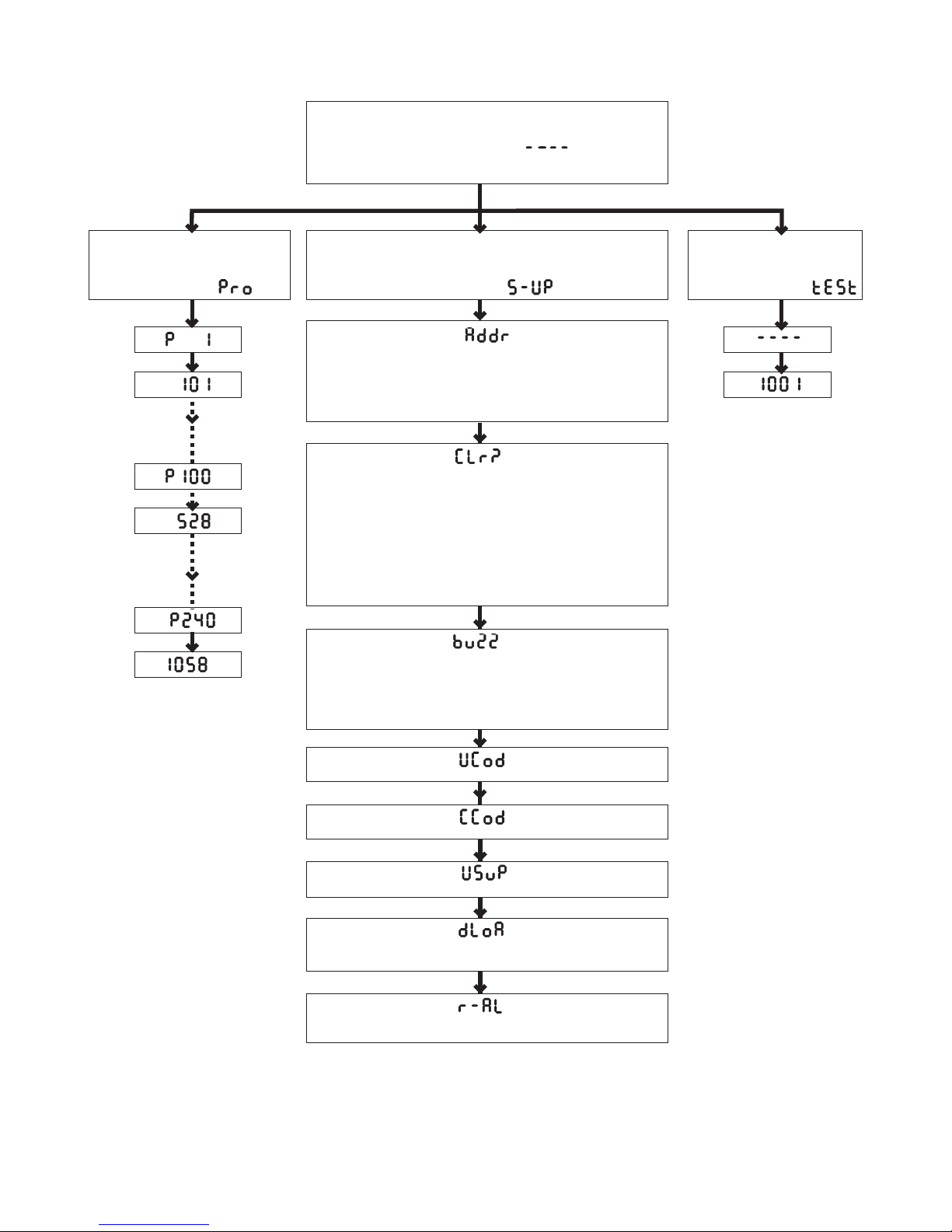
Insert the technical code (default=1111) and press the ENTER key. The Display
shows the indication PRO and the Program indicator led blinks. Now the system is
ready to be programmed.
6.1. PRO. Programming names of zones - rooms.
Insert the technical code (1111). The Display shows the indication PRO.
Press the ENTER key and the Display will show the indication P1 (this means that
the number which we will insert to the memory will correspond to terminal block 1).
Press the ENTER key again and the indication 1 appears (this is the preset name
which will appear on the Display every time that someone calls us from the zone
- room 1). If we want to change the name of the room we have to type the
number which we want to appear e.g. 101 and press the ENTER key to confirm
the process.
The Display shows the indication P 2 which is the next number of the memory
(second terminal block). Following the same process to name all the other memory
locations.
At the end of the process press successively the ESC key to exit programming mode.
6.2. SETUP. Adjusting the settings of the keyboard.
6.2.1. Address. Changing the address of the keyboard.
Insert the technical code (1111). The Display shows the indication PRO.
Press the key FAULT EVENTS until the Display shows the indication S-UP.
Then press the ENTER key again and the Display shows the indication Addr.
Press the ENTER key once more and the Display shows the indication _ _ _ 1 (this
means that this keyboard has address 1).
921746000_09_003
Page 8
0
1
2
3
4
0
1
2
3
4
5
Page 8 from 18
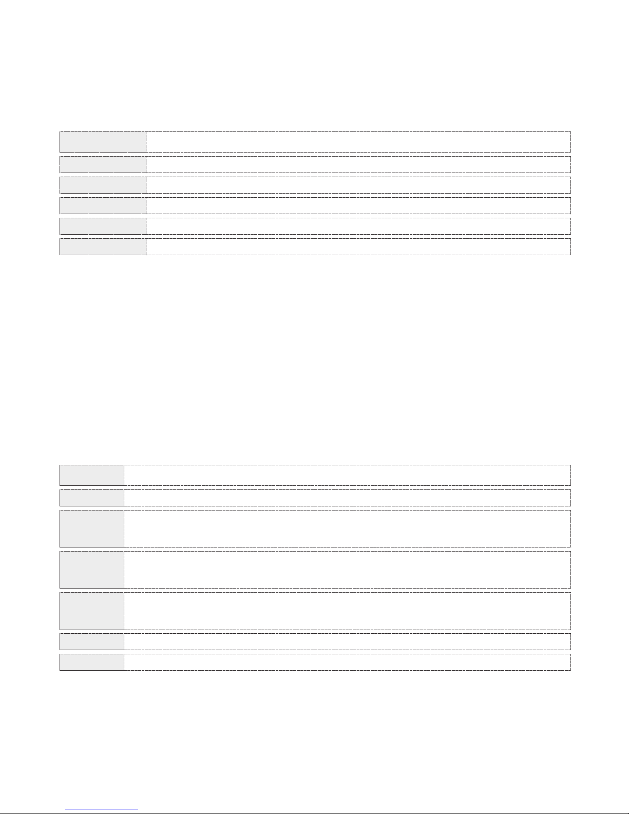
If we want to change the keyboard address we must type in the required number (1
to 4 according to the address selection table shown below) and at the end press the
ENTER key for the new value to be accepted.
At the end of the process press successively the ESC key to exit programming
mode.
ADDRESS PROGRAMMING
No communication (keyboard deactivated)
(Default) the keyboard operates as master (U1)
The keyboard operates as repeater keyboard (U2)
The keyboard operates as repeater keyboard (U3)
The keyboard operates as repeater keyboard (U4)
6.2.2 CLr?. Signal/Call resetting.
This programming operation changes the way that the user can reset the
signals/calls accepted by the system.
Insert the technical code (1111) and using the FAULT EVENTS key scroll to the
menu item S-UP and press ENTER. The indication Clr? Is shown on the display.
Press the ENTER key and the indication _ _ _ 1 is shown. (This means that this
keyboard has a value of 1) Depending on this value the calls are reset/cancelled as
shown in the table below .
If we want to change the value, press the required number (0 to 5) and then press
ENTER so the keyboard can store this new value.
At the end of the process press successively the ESC key to exit programming
mode.
VALUE
PROGRAMMING
The BUZZER ON-OFF HELP key has no affect
(default) The BUZZER ON-OFF HELP key resets only one signal
while the code 0000 resets all the signals.
The only one signal
while the code 0000 has no affect
BUZZER ON-OFF HELP key resets
The code 0000 resets only one signal while the
BUZZER ON-OFF HELP key has no affect
The all the signalsBUZZER ON-OFF HELP key resets
The code 0000 resets all the signals
921746000_09_003
Page 9
0
1
2
3
4
6.2.4 Ucod.
Changing the technical code (1111=default)
Insert the technical code (1111) and using the key FAULT EVENTS scroll to the
indication S-UP. Press ENTER and scroll to the Ucod indication using the arrow keys.
When the ENTER key is pressed the indication 1111 is shown on the display.
(This means that this keyboard has a programming - technical code of 1111).
If we want to change the code press the new four digit number (e.g. 1974) and
press the ENTER key, so as to accept the new four digit number.
At the end of the process press successively the ESC key to exit programming
mode.
Page 9 from 18
6.2.3 buzz.
Buzzer sound mode and mode operation system.
With this programming operation we can change the sound mode of the buzzer
when there is a call. Insert the technical code (1111) and using the key FAULT
EVENTS scroll to the indication S-UP, press the ENTER key and scroll to the
indication buzz using the arrow keys. Then press the ENTER key and the display
shows the indication _ _ _ 1. (This means that the buzzers sound mode is 1 ).
The table below explains the different sound mode that are available.
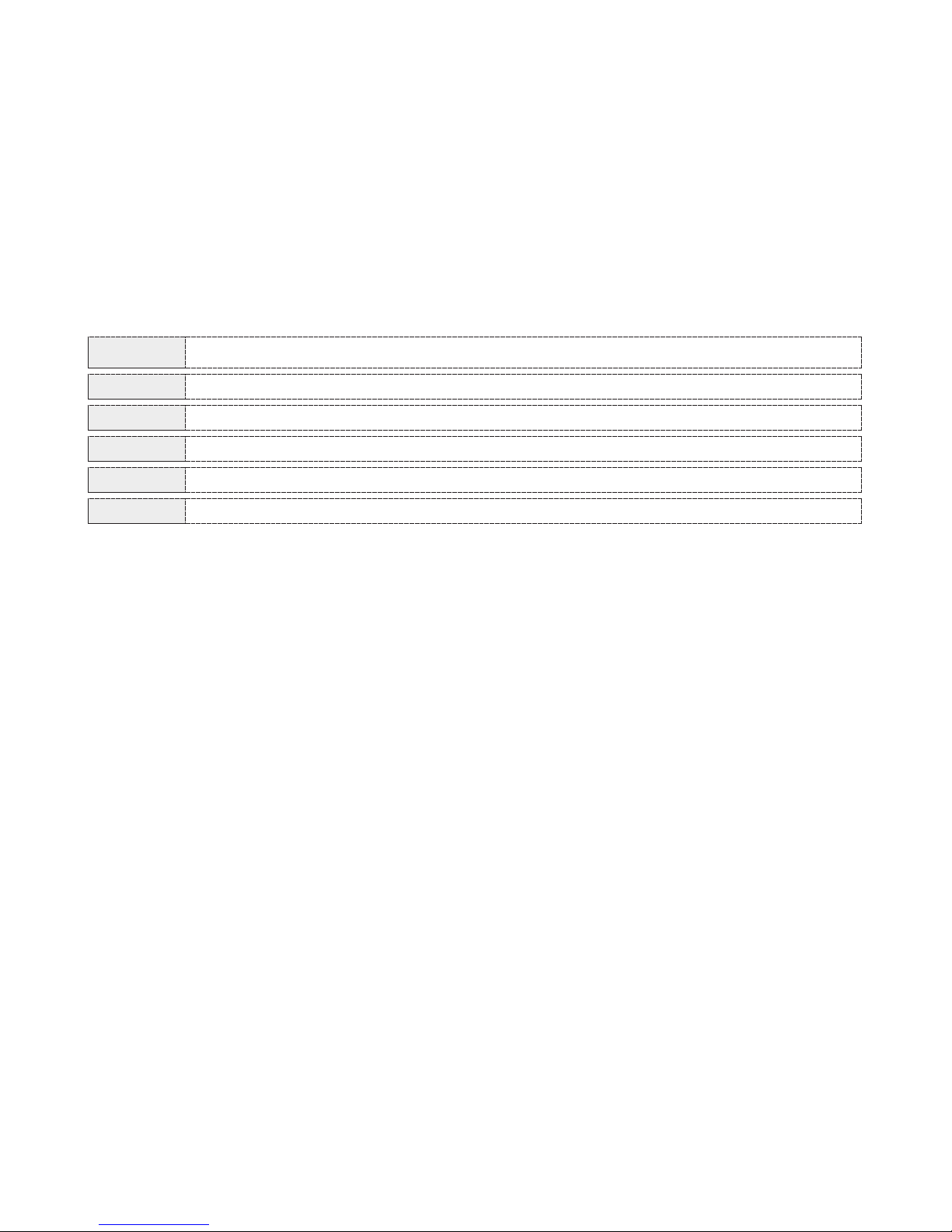
VALUE PROGRAMMING
Buzzer deactivated - Signal numerator panel operation mode
(default) 5 short sounds - Signal numerator panel operation mode
1 long sound - Signal numerator panel operation mode
3 continuous sounds - Signal numerator panel operation mode
Buzzer deactivated - Presence indication operation mode
If we want to change this value, press the required number (0 to 4)and then
press ENTER so the keyboard can accept the new value. At the end of the process
press successively the ESC key to exit programming mode.
If we give the value of 4, the buzzer will not sound. This sound mode is used only
when the system is configured to operate in Presence indication mode.
(See section 8).
921746000_09_003
Page 10

0
1
2
3
4
5
6
7
8
9
If a unit is found then the indication is shown on the display e.g. C _ _ 5, the buzzer
sounds briefly and the system stores in memory the unit that is found.
At the end of the process press successively the ESC key so as to exit programming
mode.
Page 10 from 18
6.2.5 Ccod.
Changing the user code (0000=default)
Insert the technical code (1111) and using the FAULT EVENTS key scroll to the
indication S-UP. Press the ENTER key and use the arrow keys to scroll to the
indication Ccod, then press the ENTER key so the indication 0000 is shown on the
display. (This means that this keyboard has a user code of 0000)
If we want to change the user code press the new four digit number (e.g. 1821) and
then press the ENTER key so as to accept the new value. At the end of the process
press successively the ESC key so as to exit programming mode.
6.2.6 USuP.
Connected unit recognition from the central keyboard (Master).
This programming operation recognizes all the peripheral devices (panels, repeater
keyboards ) which are connected to the main keyboard(Master). This process is
necessary and is the first step which we have to do when the panel operates for
first time.
Insert the technical code (1111) and using the FAULT EVENTS key scroll to the
indication S-UP, press the ENTER key and using the arrow keys scroll to the
indication UsuP, then press the ENTER key and the system will start to recognize
all the devices that are connected with the central keyboard (Master). The duration of
this process is a few seconds and the Display shows all the devices that the system
is searching for. (e.g. U2, U3, U4....U9, the value for every device appears in the
table below).
VALUE
PROGRAMMING
No communication
(default) Operates as central keyboard (master) (U1)
Operates as repeater keyboard (U2)
Operates as repeater keyboard (U3)
Operates as repeater keyboard (U4)
(default) Operates as central panel (master) (U5)
Operates as repeater panel (U6)
Operates as repeater panel (U7)
Operates as repeater panel (U8)
Operates as repeater panel (U9)
921746000_09_003
Page 11

6.2.7. dLoA.
Updating data on repeater keyboards using the master keyboard.
This programming operation is used to transfer the programmed rooms from the
central keyboard(master) to the repeaters keyboards. It is used only when we have
repeater keyboards connected to the system.
Insert the technical code (1111) and use the FAULT EVENTS to scroll to the indication
S-UP, press the ENTER key and using the arrow keys scroll to the indication dLoA,
then press the ENTER key and the programmed rooms will be transferred from the
central keyboard (master)to the repeater keyboards. The duration of this process is a
few seconds and the Display shows the programs in sequence. (e.g.P1, P2, P3,
P4....P240).
At the end of the process press successively the ESC key so as to exit the
programming procedure.
6.2.8. r-AL.
Clearing and resetting the keyboard to default conditions.
This programming operation resets all the names which have been programmed for
every room and returns these values to their default settings.
Insert the technical code (1111) and using the FAULT EVENTS key scroll to the
indication S-UP, press the ENTER key and using the arrow key scroll to the r-AL,
then press the ENTER key, the keyboard resets the memory and returns the default
programming values. The duration of the process is a few seconds and the Display
shows the programs in sequence (e.g.1, 2, 3, 4...P40).
At the end of the process press successively the ESC key so as to exit the
programming procedure.
Page 11 from 18
921746000_09_003
Page 12

6.3. TEST.
System check , call point and programming names
Insert the technical code (1111) and using the FAULT EVENTS key scroll to the
indication TEST. Press ENTER and the Display shows the indication ------ .
In this mode we can test the system and check if the call points which are mounted
on every room are operating and corresponding to the numbers that we have
programmed for every room.
For this test to be conducted two people are required. Also some form of
communication between them is also required (E.g. Wireless radio , intercom).
One person goes from room to room and presses the call points. The other person
verifies that all the call points are operating and that that there is a correspondence
between the call point and the displayed value.
When the call point is pressed, the Display shows the number of the zones - room
(e.g. P 1) and the room name which has been programmed (e.g. 101) .
At the end of the process press successively the ESC key so as to exit the
programming procedure.
Page 12 from 18
7. SIGNAL NUMERATOR PANEL OPERATION MODE.
This operation mode is for the user and is very simple.
When the mounting and programming process has finished and the system has been
tested and is operating then the user can do the following operations.
7.1. Starting position operation.
The system is ready to accept the calls of the zones - rooms and on the control
keyboard - unit we have the following indications.
The Display shows the indication ---- and the POWER LED is lighted (green led).
7.2. Calling from a call point.
If a call point is pressed in any room - zone, the keyboard shows the room number
which was programmed to correspond to the specific call point. The buzzer also
sounds.
7.3. Calling from more than one call points.
If two or more call points are pressed then the keyboard successively shows the
numbers from the call points that were pressed and the SIGNAL indication led lights
to indicate that we have multiple calls. The buzzer also sounds.
7.4. Resetting/cancelling indications and calls.
To reset/cancel calls press the ON - OFF BUZZER / HELP key and the call that is
shown will be reset/canceled.
921746000_09_003
Page 13

Page 13 from 18
7.5. Resetting/cancelling all calls using the user code.
In order to be able to cancel all the calls using the user code we must enable this
operation. To reset all calls using the user code simply insert the user code (e.g. 0000).
In this case all the calls will be canceled simultaneously .
7.6. Reading faults and keyboard software versions.
With F1 key we can see any communications errors that might have occurred as well
as the keyboards software version. If we have more than one communication faults then
we can view them one by one using the arrow keys.
7.7. Fault indicator LED.
If the FAULT indication LED should happen to light then this would mean that we had a
communication error and that the system is not operating normally. In this case we must
call the technician that installed the system.
8. PRESENCE INDICATION MODE.
This mode of operation is used to detect the presence of people in a room-zone after
the required programming has been done.
To use this mode we must connect a terminal in each room. This can be done using for
example a room activation switch that has a volt-free relay contact. This contact is then
connected to the zone of the panel.
To program the rooms follow the directions in section .6.1. If we want to correspond
the rooms with alias names or numbers (e.i. Zone 1 has a corresponding alias room
number 101).
In order for the system to operate in this mode it is mandatory for us to program the
keyboard to operate with buzz 4 mode as described in section 6.2.3.
After the above programming procedures are finished the system is ready to operate in
presence detection mode. Each time a person is in a room and has activated the room
using his activation card his presence in shown in the form of a room number on the
display of the keyboard. If more than one rooms are activated then they are shown
sequentially in the display.
The user also has the option of scrolling through the rooms using the arrow keys.
He can also press the ENTER key, type in the required room number and see the
status of a room.
If it is activated it will show (FULL).
If it is deactivated it will show (EMPTY).
921746000_09_003
Page 14

Page 14 from 18
9. USEFUL INSTRUCTIONS FOR FAST AND EASY INSTALLATION.
9.1. Connections.
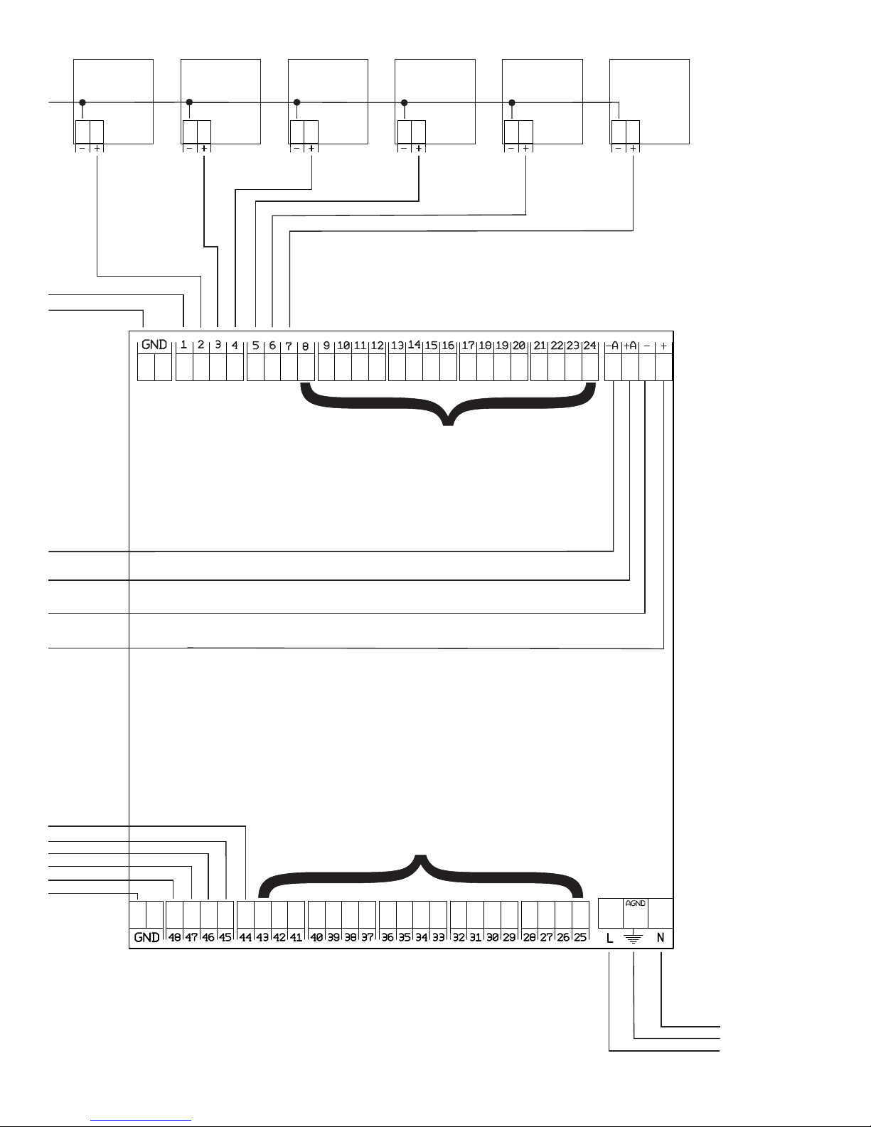
- Connect the panel BS-748 to the main power supply(230V AC).
Isolate the mains power supply before doing any connections.
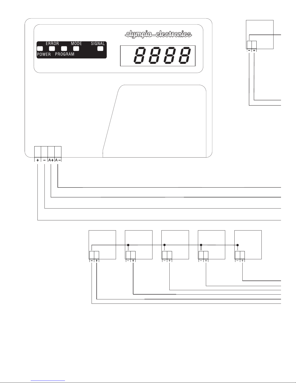
- Connect the keyboard BS-746 with 4 wires to the panel BS-748
(+, - used for supply purposes , +A, -A used for communication purposes)
- Connect the call points on the zones 1 to 48( Common ground, One wire from
each call point to one zone terminal block)
9.2. Address adjustment.
- Check that the panel BS-748 has the address 5 (default).
- Check that the keyboard has the address 1(default).
9.3. Recognize peripheral units.
- Type the technical code (1111) and the Display shows the indication PRO.
Press the FAULT EVENTS key and the Display shows the indication S-UP, then press
ENTER and use the arrow keys until the Display shows the indication UsuP. After that
press the ENTER key and the system will start the unit recognition procedure. This
procedure last for a few minute and the display shows the units that are searched for by
the keyboard in sequence (U2, U3, U4...U9,). If the keyboard detects a unit it will report
it. (e.i. C _ _ 5) . The buzzer sounds briefly and the detected unit is stored in memory.
After finishing the detection process press the ESC key as many time as it is required in
order to exit programming mode.
9.4. System checking and testing.
Checking the BS-748 panel
-Check the three indications LEDs on the BS-748 panel.
The green power LED must be lighted.
The red mode LED must be lighted.
The yellow communications LED must be blinking.
Checking the BS-746 keyboard
-Check the following BS-746 keyboards indications.
The green POWER LED must be lighted.
The Display shows the indications - - - - -When someone activates a call point, the Display shows the number which
is programmed (e.g. 14)
Checking the call points.
Activate a few call points(rooms) and check if the correspond numbers appear
on the keyboard`s display .
9.5. Operation - Resetting/canceling calls
- Press the ON-OFF BUZZER / HELP to reset the accepted call one by one.
921746000_09_003
Page 15
Page 15 from 18
MAIN MENU
TECHNICAL ACCESS CODE 1111
PROGRAMMING
MENU
SETUP
MENU
TEST
MENU
0 Does not communicate
1 (default) operates as central keyboard (master) (U1)
2 operates as repeater keyboard (U2)
3 operates as repeater keyboard (U3)
4 operates as repeater keyboard (U4)
0 Resetting cannot be done
1 (default) the CLEAR key resets only one call
while the code 0000 clears all the calls.
2 The CLEAR key resets only one call while
the code 0000 has no affect
3 The code 0000 resets only one call while
the CLEAR key has no affect
4 The CLEAR key resets all the calls
5 The code resets all the calls
Change the technical code
Change the user code
Recognize units which are connected with the central keyboard (Master)
Update information on the repeater keyboards from the
main keyboard (master).
Resetting all options on the keyboard to default settings.
INDICATION
INDICATION
INDICATION
INDICATION
BS-746. TECHNICAL MENU
FLOW CHART - COMMAND MENU FOR EASY AND FAST INSTALLATION .
0 Buzzer deactivated - Signal numerator panel operation mode
1 (default) 5 shorts sounds -
2 1 long sound - Signal numerator panel operation mode
3 3 endured sounds - Signal numerator panel operation mode
4 Buzzer deactivated - Presence indication mode
Signal numerator panel operation mode
921746000_09_003
Page 16
Call point
Page 16 from 18
Call point Call point Call point Call point Call point
921746000_09_003
Page 17
230V AC
Page 17 from 18
Call point Call point Call point Call point Call point Call point
The cal l po ints th at are co nn ected t o the ter mi nal blo cks
8-24 ar e conne ct ed in the s am e manne r as the
call po in ts on the t ermin al b locks 1 -7
The cal l po ints th at are co nn ected t o the ter mi nal blo cks 25- 43 a re
conne ct ed in t he s ame man ne r as the
call po in ts on the t ermin al b locks 4 4-48
921746000_09_003
Page 18

Page 18 from 18
921746000_09_003
 Loading...