

Page 1
BS-634, BS-636
4 and 6 zone Fire Detection Panels
92163 6 0 0 0_ 0 9_ 0 23
Thank you for purchasing this product of Olympia Electronics. A European manufacturer.
GENERAL
The family of fire detection panels consist of 2 types( 4 and 6 zone) with identical operation and indications. The panels have
2 independent siren outputs, Alarm relay, Programmable output for telephone operators and a relay per zone . The required
battery for the panels is the type Α-986 (12V/7Ah). All functions and indications are according to European Norms ΕΝ 54-2
and EN 54-4.
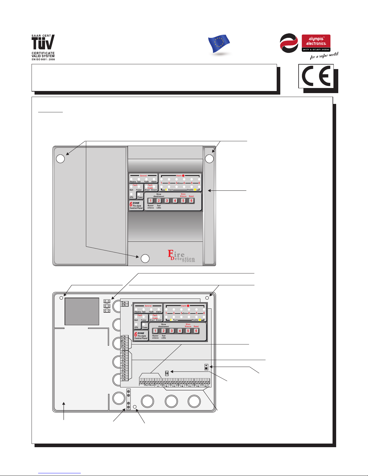
To p c o ve r
re t a in ing s c rew s
Co n t ro l Key b oar d a n d
in d i ca tio n l eds
Mo u n ti ng ho l es
Ba t t er y com p art m e nt
Α- 9 8 6
MO D E s el ect i on
mi c r os wit c h
Re l a y pe r zon e
co n n ec tio n t erm i n al s
Zo n e c on nec t ion t e r mi nal
Ge n e ra l out p ut co n n ec tio n ( Sir e n s,
re l a y al arm , 24V )
P
+A
_
A
Op e r at ion a d jus t m en t
of z o n e re lay
Ma i n s vo lta g e con n e ct ion
te r m in al bl o ck (2 2 0 -2 40V AC )
Figur e 1. Schema tic d iagr am of t he panel
Mo u n ti ng ho l e
Ex t r a ea rth
te r m in als
Page 1 fr o m 9
High Quality European based Manufacturers
Page 2
Ind icat ion LE D desc ript ion
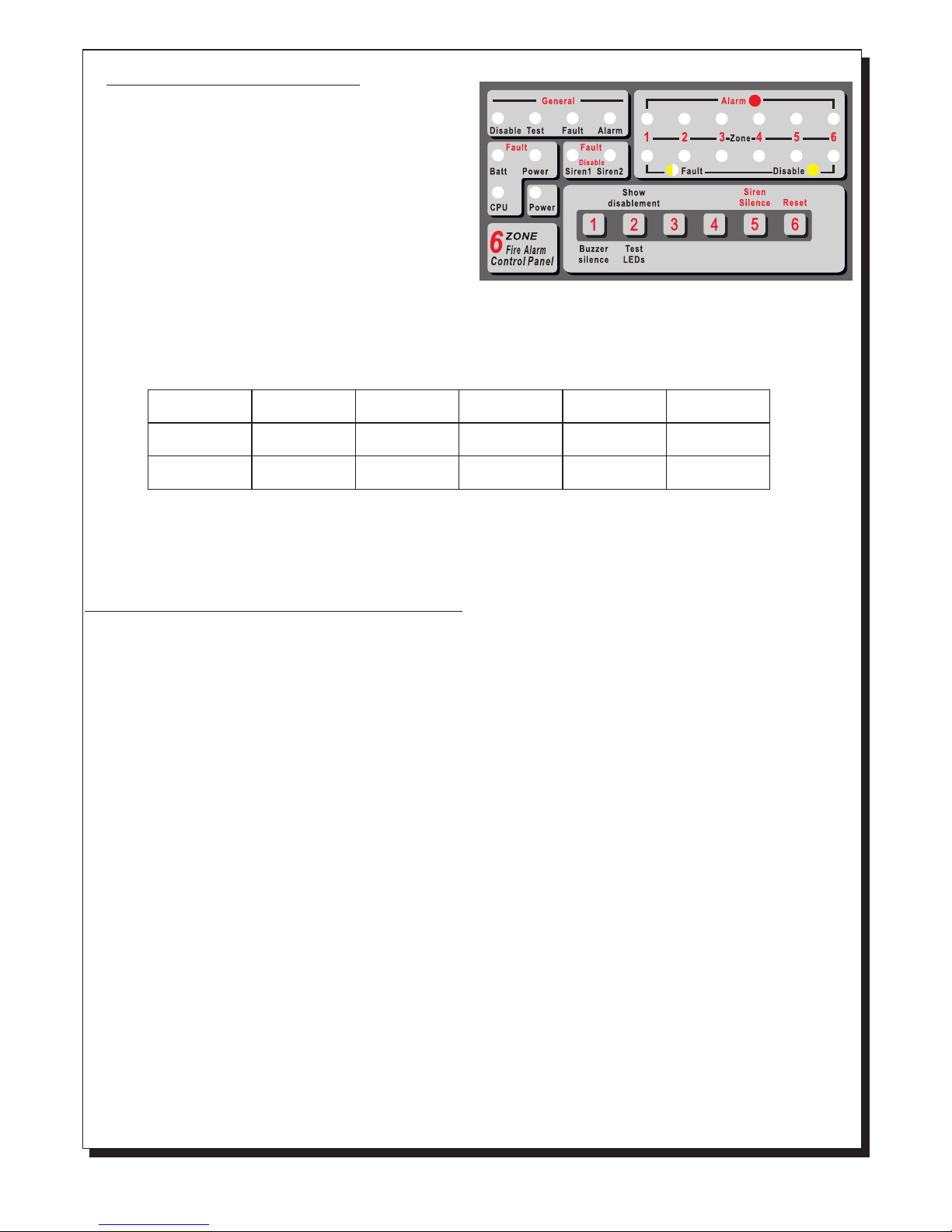
The schematic shows the control keyboard and the
indication plate of a 6 zone BS-636 panel. Starting from the
top left side we can see 4 indicators marked 'General'.
The 'Disable' LED lights in every DISABLE condition.
The 'Test' LED lights in every TEST condition .The panel
does not has test condition as specified in 11 of EN 54-2.
The 'Fault' LED lights in every FAULT condition. Blinks
when we have a FAULT and the buzzer is silenced.
The 'Alarm' LED lights when we have an ALARM condition.
Blinks when we have an ALARM and the buzzer is silenced.
The next group of indicators is the 'Alarm' indication LEDs.
These indicators light when a corresponding zone issues an ALARM condition. Below this group we have the
'Fault/Disable' indication for each zone. When the panel monitors an open or short circuit conditions in a zone then the
corresponding LED will blink. If a zone is disabled the corresponding LED will light.
Below the `General` indicator group we can find the indication group called `Fault`. The 'Batt' LED and 'Power' LED in
combination, show us faults concerning the power supply. These combination are shown in the panel below.
Ba t t F a u l t
Po w e r F a ult
La c k o f
AC v o l t a g e
Ba t t e r y
Ov e r c h a rgin g
Ba t t e r y
Di s c h a r ged
Ba t t e r y
Ab s e n t
Ch a r g e r
Er r o r
Lights
----
Lights
Lights
Lights
Blinks
Blinks
Lights
Blinks
Blinks
The 'CPU' LED lights to indicate a problem with the main processor unit (System fault).
The green 'Power' LED lights to indicate valid internal voltages and blinks when the mains AC power supply fails.
.
The LEDs marked 'Siren1' and 'Siren2' correspond to the siren outputs. If a siren out has a short circuit or open circuit then
the corresponding LED will blink. If a siren is disabled the corresponding LED will light.
Con trol k eybo ard de scri pti o n/o p era tion
The panel is controlled/ operated using the six numeric keys (1 to 6) found on the front panel. When a key is pressed a short
tone is issued.
The panel has three access levels.
Access level 1:
has all the functions that can be done directly from the user without using a code. These operations are:
Buzzer silence / Buzzer reactivation . If an alarm of fault condition is issued then the internal buzzer will sound. Pressing
the "1" key will silence the buzzer. ( The buzzer sounds periodically once every minute.) Pressing this key again will reactive
the buzzer.
Viewing disabled sirens-zones/Lamp test. Pressing the "2" key will have the following affect. If any sirens are disabled
then the panel will issue 3 short tones, by lighting the ‘General Disable’ LED, and the disabled sirens will be shown by
lighting the corresponding LEDs Siren1 and Siren2 of the disabled sirens. Then the LEDs will stop lighting and the panel
will issue again 3 short tone, by lighting the ‘Zone Disable’ LED, and the disable zones will be shown by lighting the
corresponding LEDs of the disabled zones. After a while these indicators are switched off and a lamp test is conducted by
lighting the LEDs. The panel then returns to normal operation. The above tests can be conducted only if the panel is in
quiescent state (No fault or alarm conditions).
Access level 2:
Includes all the functions that the user can do and an access code is required. The code is "34”, it is the same for all panels
and cannot be changed. The functions that can be implemented using this code are the following:
Siren Silence. When an alarm is issued and we want to silence the sirens then we must enter the user code
( 34 ) and then the keys number '5' and '5'. The sirens are silenced but the internal buzzer continues to sound. The panel
remains in normal operation. A new alarm from another zone will resound the sirens.
Panel Reset. When an alarm or fault condition has occurred and we want to reset the panel we must enter the user code
(34) and then the keys number '5' and '6’. The panel lights all LEDs in sequence and then enters normal operation.
Zone enable/disable. If we want to disable the operation of specific zones then we must enter the user code
( 34 ) and then the keys number '5' and '4'. The LED marked 'General disable' start to blink, and if a zone is disabled the
Page 2 fr o m 9 92163 6 0 0 0_ 0 9_ 0 23
Page 3
Access level 3:
These functions are implemented during the installation and need the technical code to be accessed. The technical code is
"364", it is the same for all panels and cannot be changed. These functions that can be implemented using the technical
code are activation methods used for the relays and can be done only if the panel has not issued an alarm or fault condition.
These functions are ancillary and not required by the EN 54-2.These methods of programming are:
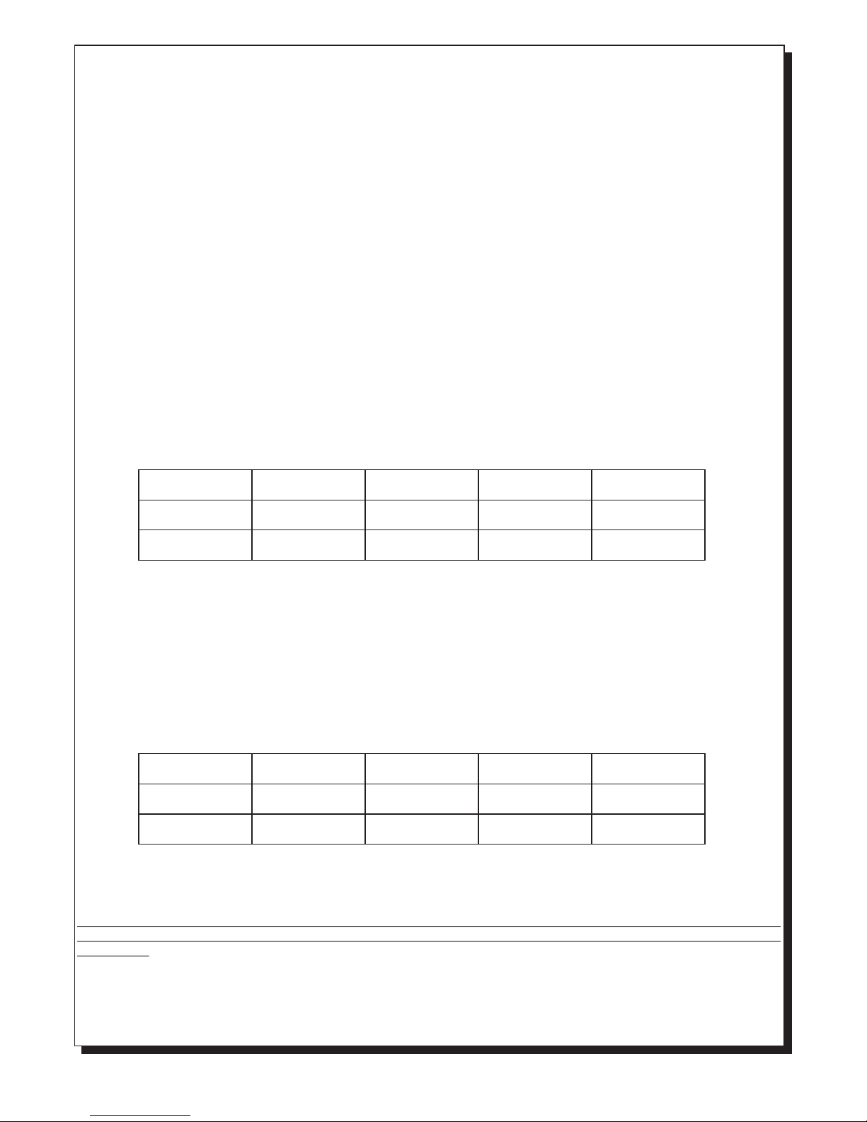
AUX RELAY programming. If we want to program the operation behaviour of the AUX RELAY we must enter the technical
code ( 364 ) and then press the number key '5'. The 'General fault' and 'General alarm' LEDs start to blink . The Alarm LED
of zone 1 and zone 2 show the way the AUX RELAY is programmed according to the table below.
corresponding 'Alarm' LED lights to indicate this. Using the keys 1, 2, 3, 4, 5 and 6 we can enable or disable the
respective zones. The disabled zones light the corresponding LED. The panel exits this mode if no key is pressed for
more than 30 seconds. The panel then conducts an automatic RESET and enters normal operation mode. All disabled
zones are supplied with the proper voltage but cannot issue an alarm or fault condition. If we have disabled zones then
this is indicated with the indicators 'General disable' and the corresponding Disable LED zone and the buzzer sounds
once every minute.
Siren enable/disable: If we want to disable the operation of specific sirens the we must enter the code (34) and then the
keys numbers '6' and ‘6’. The LED marked 'General Test' start to blink, and if a siren is disabled Siren1 LED lights for
siren 1 and Siren2 LED lights for the siren 2. Using the keys 1 and 2 we can enable or disable the respective sirens. The
disabled sirens have a LED lighted. The panel exits this mode if no key is pressed for more than 30 seconds. The panel
then conducts an automatic RESET and enters normal operation mode. All disabled sirens are supplied with the proper
voltage but the panel cannot enable them or read their condition. If we have disabled sirens then this is indicated with the
indicator 'General disable' and the buzzer sounds once every minute.
The default setting of this relay is set to be activated from a general alarm and immediately with no delay. In this
programming mode if the keys '1' and '2' are pressed , we can toggle the LEDs ON or OFF until we archive the desired
behaviour according to the table above. In order to exit this programming mode and to store the settings in memory press
the key '6' or do not press any key for more than 30 seconds. This system will conduct an automatic RESET and will enter
normal operation mode.
ZONE RELAY programming. If we want to program the operation behaviour of the zone relays then we must enter the
technical code ( 364 ) and then press the number key '5'. The 'General fault' and 'General alarm' LEDs start to blink. The
Fault/Disable LED of zone 1 and zone 2 show the programmed activation method of the zone relays according to the table
below.
The default operation method for the zone relay is set to permanent activation. Using the keys '3' and '4' we can
toggle the ON or OFF state of the LEDs until the desired activation programming has been reached. In order to exit this
programming mode and to store the settings in memory press the key '6' or do not press any key for more than 30 seconds.
This system will conduct an automatic RESET and will enter normal operation mode.
We can also program the RELAY so that it can cooperate with BS-680 or BS-684 type electrovalves by shorting
the adjustment jumper. In this case the RELAYS are activated for 10sec. during the alarm. After 10sec. they are
deactivated.
RESOUND sirens. It is possible to configure to automatically re-sound the sirens following an alarm in another zone. You
must enter the technical code (364) and then press the number key '5'. The 'General fault' and 'General alarm' LEDs start to
blink. If the Alarm zone 4 led is off the sirens resound following an alarm in another zone else if the led is on the sirens does
not resound. By pressing the key '5' you can change the configuration.
LE D A larm zo n e 2
Fa u l t z o ne 2
LE D A larm zo n e 1
Fa u l t z o ne 1
Ge n e r a l Al a r m
Di r e c t a ctiv a t i on
Pe r m a n ent
ac t i v a tion
Ge n e r a l Al a r m
De l a y 4 5 sec
Ac t i v a ted fo r
10 s e c
Ge n e r a l Al a r m
De l a y 2 m i n
Ac t i v a ted fo r
30 s e c
Ge n e r a l Faul t
Di r e c t a ctiv a t i on
Ac t i v a ted fo r
60 s e c
LED Off
LED Off
LED Off
LED Off
LED On
LED On
LED Off
LED Off
LED Off
LED Off
LED On
LED On
LED On
LED On
LED On
LED On
Page 3 fr o m 9 92163 6 0 0 0_ 0 9_ 0 23
Page 4
Conne ct ions
The two panels in the family have the same connections. The main differences in these panels is the number of zone
available and the number of zone relays. The common outputs, the maximum consumption and the operation
procedures are identical for all the panels.
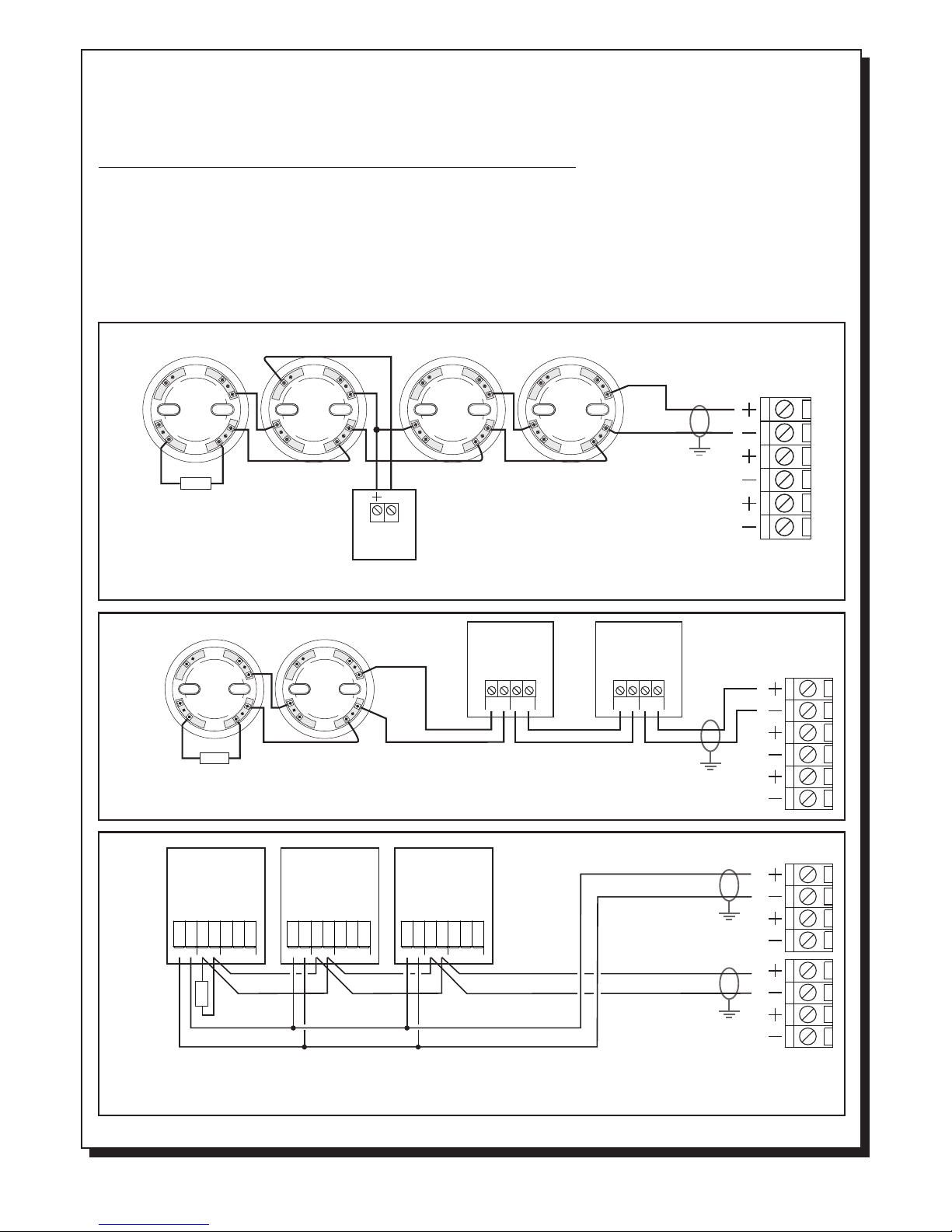
Connecting detectors and break-glass call points to zones.
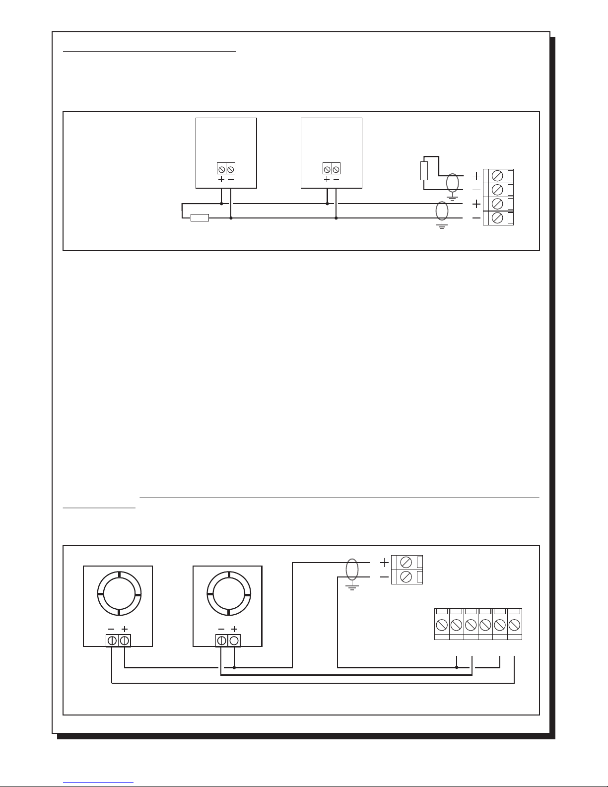
By default each zone terminal block has a pre-installed terminal resistor (5Κ6). This resistor must be removed and
installed on the last device of the zone or is left connected on the zone terminals if the zone is not used. The connections
to all the zone are identical. What is shown in figures 2, 3 and 4 for zone 1 is valid for all the zones.
The total number of connected devices per zone is 30.
All cable zones must be insulated, to earth ground, to meet EMC requirements.
The cable length for each zone must not exceed the 1.5 kilometres with a cross section cable of 1.5mm².
Page 4 fr o m 9
Figur e 2. Connec tin g 4 dete cto r bases to zo ne 1. Each ba se can acce pt BS-655 , BS-660 or B S-667
detec tors. A remote i ndicati on LED BS-5 72 is c onne cte d to one of the d etector s.
Figure 3. Connecting 2 ca ll poi nts BS -536 a nd 2 det ecto r base s to the s ame zo ne.
Figur e 4. Connec tin g
these d etector s mus t also be con nected to t he termin als 2 4V_M in ord er to be supp lied with p ower.
3 Gas det ectors BS -68 5 or BS-686 . Besides t he connec tio ns to the zon e termina ls
Ζ1 Ζ2 Ζ3Ζ1 Ζ2 Ζ3
5Κ6
BS-572
remote
LED
R
Terminal
resist or
Ζ1 Ζ2 Ζ3
Break-glass
call point
BS-536
OUT IN
Break-glass
call point
BS-536
OUT IN
Detect or
base
Detect or
base
Detect or
base
Detect or
base
5Κ6
Terminal
resist or
Ζ1
F_ O U T
24 V _ M
Ζ2
5Κ6
Terminal
resist or
ZON E
10- 30V
NCNO C
Gas
Detector
BS-685
ZON E
10- 30V
NCNO C
BS-685
Gas
Detector
ZON E
10- 30V
NCNO C
BS-685
Gas
Detector
-R
O
U
T
-
-
L
N
I
T
+
U
R
O
N
+
L
I
-R
O
U
T
-
-
L
N
I
T
+
U
R
O
N
+
L
I
-
R
O
U
T
-
-
L
N
I
T
+
U
R
O
N
+
L
I
-
R
O
U
T
-
-
L
N
I
T
+
U
R
O
N
+
L
I
-
R
O
U
T
-
-
L
N
I
T
+
U
R
O
N
+
L
I
-
R
O
U
T
-
-
L
N
I
T
+
U
R
O
N
+
L
I
Detect or
base
Detect or
base
92163 6 0 0 0_ 0 9_ 0 23
Page 5
Besides the terminals t hat we re des crib ed up to n ow the p anel a lso ha s the fo llowing outputs :
24V_M: A 24Vdc output tha t is interrupted i n the event of a pane l r eset . It is mainly used f or powering gas
detectors or other device s t hat need an inte rrupted power sup ply when the pan el is res etti ng. If this outp ut
is short-circuited th en the L ED mar ked 'G ener al fau lt' is l ight ed.
24V_P: A 24Vdc power output that is not interrupted in th e event of a reset. It ca n be used to power
electromagnetic doo r latc hes.
Relay AUX : Vol tage f ree relay con tacts that b y default are p rogrammed to ope rate w hen the p anel i ssues
an alarm condition.
Zone Relays : Voltage free relay contacts that are activated in the event of an ALARM on the
corresponding zone. A ll panels offer a relay per zone. We can use these conta cts to activate devices or
operations that mus t be d one w hen a spec ific zone issues an alarm ( i.e. Activating electrom agne tic d oor
latches, activating e lect ro-v alve s ). Fig ure 6 sh ows su ch an in stallation.
ATTENTION: Zones and aux relays are rate d a t 3 0VDC an d 5A maximum. No 230VAC signals can b e
connected to this r elay s.
F_OUT ( Faul t Output) : T his output is by default pro gram med to operate in every faul t condition issued
by the panel.
If it is required that this output be activat ed b y an alarm condi tion the n we mus t set the MODE swi tch 2 to
the ON positi on ( To mee t th e re quir ements paragraph 8.8 of E N 54 -2 the MOD E switch 2 must be placed
to OFF positi on). This output is an open-collector out put suitable fo r controlling the BS- 489 telephone
operator.
OUTPUT +A,-A. This output is used o nly for p rodu ctio n propo ses. This m ust not be use d by any other
technician only techn icia n from o lymp ia ele ctro nics .
Sir en - Sou nder C onne ctio ns
Each panel offers 2 independent circuits for connecting sirens, bells or other devices that need 24Vdc in order
to operate. Each circuit can supply a maximum of 300mA. Each terminal block by default has a pre-installed
terminal resistor (5Κ6). This terminal resistor is either removed and installed on the last siren of the line or is
left on the terminal block if the circuit is not used.
The connections of both circuits are identical.
Figure 5. Connect ing 2 BS -531 s iren s to the AL ARM 2 ou tput . Thi s connection requires polarity.
BS-531
Siren with
Beacon
BS-531
Siren with
Beacon
5Κ6
AL ARM 1 A LA RM2
5Κ6
Termi nal
Res istor
Termi nal
Res istor
Figure 6. Connecting
zone 1 and the other by zone 2.
2 electromagnetic doo r latc hes BS -510 /24 to t he pan el. On e is act ivat ed by
ZO NE 1 ZO NE 2
24 V_P
C C
NO NONC N C
24 V D C 24 V D C
BS-5 1 0 /2 4BS-5 1 0 /2 4
Page 5 fr o m 9 92163 6 0 0 0_ 0 9_ 0 23
Page 6
Ins tall atio n
In orde r t o m e e t EM C re q ui r em e nt s , co n ne c ti o ns o f pe r ip h er a ls t o t he p an e l mu s t be d o ne u si n g
shiel d e d c a bl es .
(220- 2 4 0 V AC)
The pan e l h a s ho l es o n t he b a ck s id e f or a l l th e w ir in g t o pa s s th r ou gh . Yo u c a n c on n ec t ca b le s w it h
max. Co n d u ct o r di a me t re o f 2. 5 mm t o t he p a ne ls t e rm i na l b lo ck s .
The mains power supply wiring must use a double insulation cable.
The con n e c ti o n wi t h th e m ai ns p o we r s up p ly m us t b e do n e to t h e te rm i na l b lo c ks l oc a te d o n th e pa n el s
up left a r e a . Fi g ur e 8 .
Bat tery c onne ctio n
The bat t e r y c om pa r tm e nt h a s th e ap p ro p ri at e d im e ns i on s fo r Α -9 8 6 ba t te ry o f o ly m pi a e le ct r on i cs .
The ch a r gi ng unit on PCB is also calcul a t e d for the sp e c i fi c bat t e r y. Repla c e the ba t te r y only wi th one of
the same typ e .
From the PCB , are conn e c t ed two ba t t e ry wire s with a spec i a l te r m i na l on the ed g e . They mus t be
conne c t e d to the two b at t er y p o l e s. C o n n ec t t h e bl a c k w i r e t o th e neg a t i ve po l e (m a r k ed ( - ) or a b l ac k
mark) and th e red wire to pos i t i ve pol e (mar k e d (+ ) or a r ed ma r k ) .
The ins t a l la t io n o f th e p an el m u st b e c ar r ie d ou t b y qu a li f ie d pe r so n ne l o nl y.
Disco n n e ct p o we r b ef o re s er v ic i ng .
Never i n s e rt o r r em o ve b o ar ds o r c om p on e ts w it h t he p o we r o n.
Durin g i n s ta l la t io n u se g ro u nd e d an t is ta t ic w r is t b an d to p r ot e ct t h is e qu i me n t fo r m ES D.
The pan e l m u st b e i ns t al l ed p er m an e tl y. It is not a l l o we d t o co n ne ct t h e de v ic e d ir ec t ly t o a ny s o ck et outle t .
Mount i n g t h e pa ne l t o th e w al l
The sit e c h o s en f or t h e lo c at i on o f th e p an e l sh ou l d be c l ea n a nd d ry a n d no t s ub j ec t to s h oc k o r
vibra t i o n.
In page 1 s h o w s th e m ou n ti n g ho le s o f th e p an e l.
The pan e l m u st b e p la c ed a b ov e 1m f r om t h e fl o or a nd a n d 1m b e lo w t he c ei l in g a nd m u st h av e
dista n c e 3 0c m f ro m a ny o t he r d ev ic e s. N o o th e r po we r l in e s mu st p a ss b e hi n d th e pa n el , o nl y t he
suppl y c a b le s o f th e p an e l.
Cabli n g
Each sc r e e n or s h ie l d br a id m us t p ro p er l y be c on n ec t ed t o t he e ar t h te r mi n al b lo c k pr o vi d ed , th u s
ensur i n g t he s h or t es t p os ib l e pa t h.
The max i m u m co n du c to r d ia me t er s i ze , w h ic h ca n b e te r mi n at ed , i s 2, 5 mm ²
Conne c t i n g th e ma i ns p o we r s up pl y
The main supply must include an earth conductor connected to the fixed installation earthing system of the building.
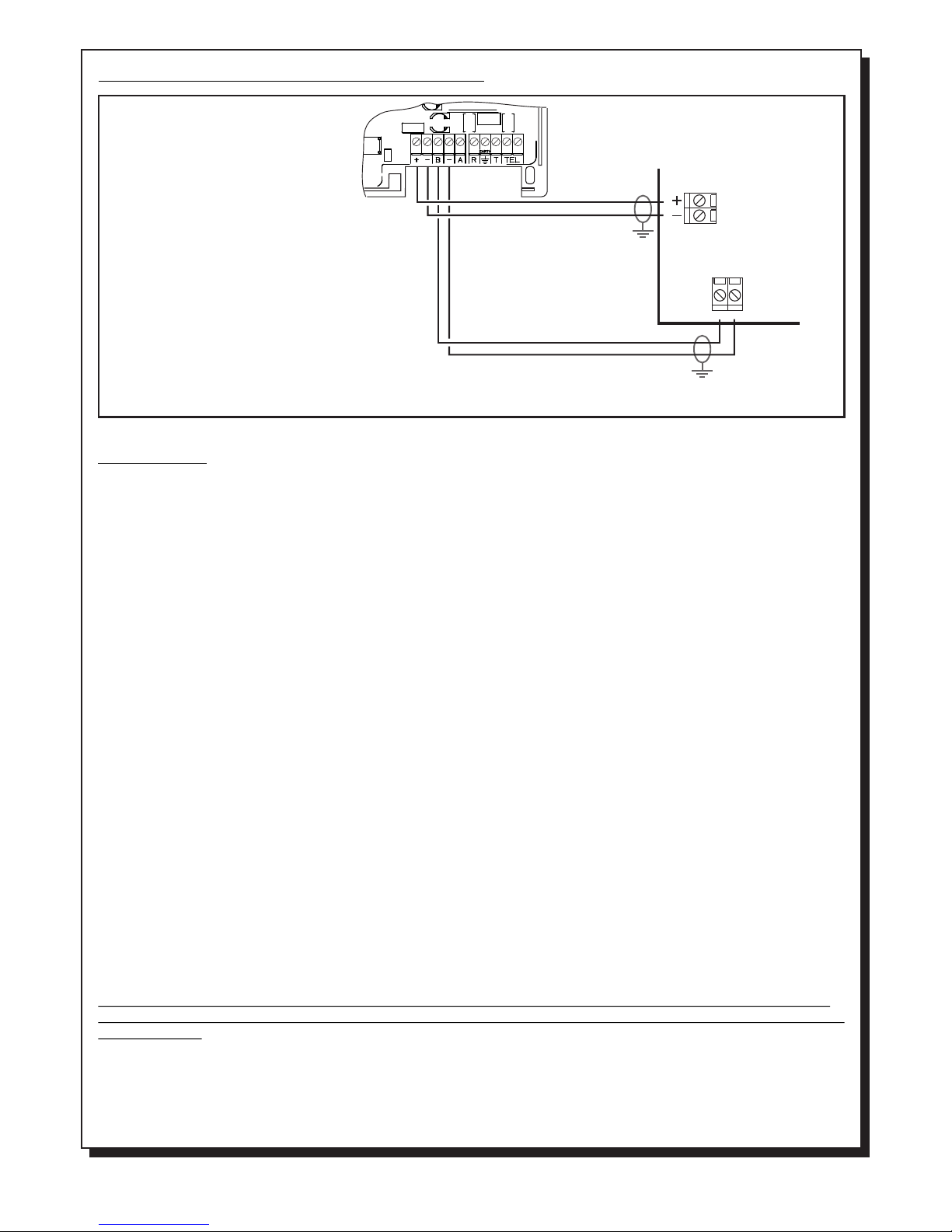
Figur e 7 . C o n ne ct i on d i ag r am o f BS - 48 9 t el e ph on e o pe r at o r.
24 V_P
-
+
Mo d e 2 O N - Al a r m
Mo d e 2 O F F - Fau l t
F_OUT
Fir e Dete ctio n
Pan el
In orde r t o u s e t he B S- 4 89 i n a la rm
condi t i o ns
in
fault c o n d it i on s
we must s e t t h e M OD E
switc h 2 t o t h e O N po si t io n , wh il e
we must s e t t h e M OD E
switc h 2 t o t h e O FF p os i ti o n.
Connecting the BS-489 telephone operator
Page 6 fr o m 9 92163 6 0 0 0_ 0 9_ 0 23
Page 7
Bat tery d ispo sal .
I s not al l o w e d t o di s ca rd ba t t er i es in to com m o n tr a sh bi n s , t h ey mu s t be di s c ar d ed on l y
Wa rnin gs.
1. Serv i c e a nd m a in t en c e ac t iv it i es s h ou l d be d on e o nl y w he n t he d e vi ce i s d is c on n et ed f r om t h e
mains p o w e r s up pl y a nd t h e ba t te ry.
2. Duri n g t h e i ns ta l la t io n t he c o nn ec t io n s to t h e ma in s p ow e r su p pl y a nd t he b a tt e ry m u st b e
done af t e r a l l ot he r c on n ec t io ns a r e fi n is h ed .
3. The pa n e l c o nn ec t io n w it h t he m a in s su p pl y m us t b e do n e vi a a1 0 A exte r n a l fu s e or a n
autom a t i c c ir cu i t br e ak e r ra te d a t 10 A .T hi s f us e h as t o b e a se p ar at e , la b el e d fu se .
4. Al w ay s u se c a bl e s wi th d o ub l e in s ul a ti on .
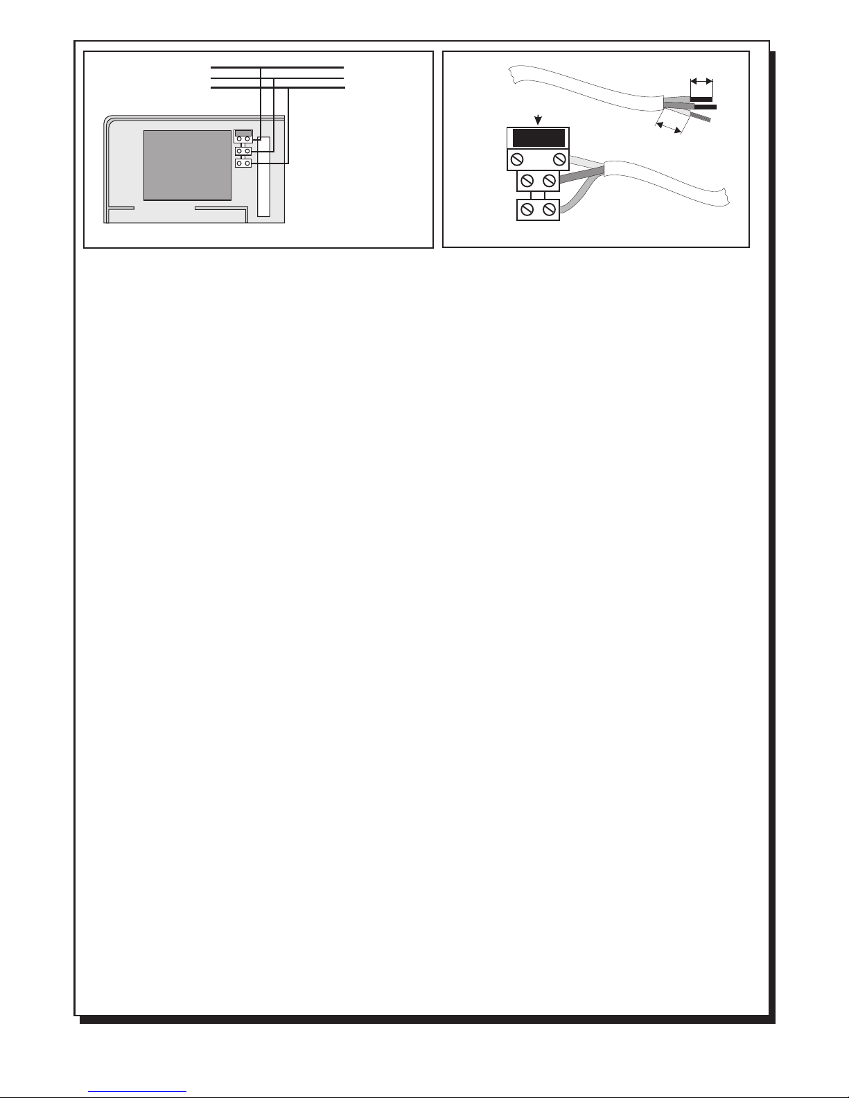
5. The di a m e t er o f th e c ab l e mu s t be a t le a st 1 m m. ( Fi gu r e 9)
6. The in n e r i n su la t io n o f ea c h ca b le m us t n ot b e c ut m o re t ha n 1 cm ( F ig u re 9 )
7. The ou t e r i n su la t io n m us t n ot b e c ut m or e t ha n 1 cm a w ay f ro m t he i n te r na l in s ul a ti o n.
8. The pa n e l ' s in te r na l f us e i s T2 5 0m AL 2 50 V w it h 5 x2 0 di m en s io n s.
9. The ba t e r y f us e is a r e se t ab l e fu se 3 A in s i d e th e p an e l.
When the connections to zones, sirens and other required outputs are finished the n w e m u s t c o n n e c t t h e m a i n s
power supply. In order to aid the installer during the initial i n s t a l l a t i o n , t h e p a n e l o ffers a special c o n f i g u r a t i o n . This
configuration is entered by setting MODE switch 1 to the ON position. Af t e r e n t e r i n g t h i s m o d e t h e p a n e l c o n d u c t s
an auto reset and the 'Power', 'Zone disable' and 'General disable' LEDs blink. The special functions that aid in
working out various problems that might arise are :
If all the pr oblems ar e corrected and th e installation is opera tin g normal ly th en the MODE switc h 1 must be place d in
the OFF position. The panel con duc ts a au to- res et an d is r ead y for opera tio n.
By using a special operation mode we can conduct a walk test of th e sys tem . To enter walk-test mode set the MOD E swi tch 1
to t he ON po sit ion . The ' Pow er' , ' Zon e dis able' and 'G ene ral d isable' L EDs blink. If an al arm i s m anu all y given by ei ther
activating a BS -53 6 call point or by activating a sm oke detector with sm oke or simul ate d smoke particles th e corresponding
Alarm LED of the zone will light and the sire n wi ll soun d for 2 seconds. Usi ng this met hod we can test the oper ati on of th e
zones.
In this state if we pre ss the nu mbe r k eys 1, 2, 3, 4, 5 a nd 6 then the corresponding zon e r ela y w ill be ac tiv ate d. All
devices that are connected to the se rel ays will also be activated indicating that the y are opera tin g prop erl y. Afte r
finishing the walk t est set th e MODE s wit ch 1 to the O FF position. The pane l con ducts an au tom atic r ese t and en ter s
normal operation mode .
The optional function w hic h is pr ovi ded b y the p ane l is th e fir e ala rm de vic es pa ragraph 7.8 of 54-2.
t i in bat t e r y
recyc l i n g p o i n t s.
Initi al I nstal la tion
When a zone has an open circu it then the internal buzzer sou nds and the corr esp ond ing LED ligh ts. If the
problem is corrected then th e buz zer i s dea cti vat ed an d the L ED is e xti ngu ish ed.
When a zone has a sh ort circuit then the internal buzzer sounds and the correspon din g LED blink s. If the pro ble m
is corrected then the buzzer is deactivated and the LED is extinguished.
When a siren out put has an ope n ci rcu it the n th e in ter nal buzzer is act iva ted and the correspondin g faul t LE D
lights. If the problem is corrected then the buzzer is deactivated and the LED is extinguished.
When a sir en outpu t has a sho rt circu it then the inter nal buzzer soun ds and the correspondin g LED blin ks. If the
problem is corrected then the buzzer is deactivated and the LED goes Off.
When a bat ter y fault e xis ts then t he 'Batt fa ult ' LED lig hts and the ' Pow er fault' LE D blinks. If the problem is
corrected then the LEDs are deactivated.
Walk - Testing
Optional Function of EN 54-2.
Figure 8. Panels connection with 220-240V AC.
220- 2 40V AC
L
N
1 cm
Fuse: T250mAL250V (5x20)
1 cm
Figure 9. Panels co nnec tion w ith 22 0-24 0V AC
PE
Page 7 fr o m 9 92163 6 0 0 0_ 0 9_ 0 23
Page 8
Certification
The 6 zo n e fire de t e c t i o n pa n e l BS-636 is ce r t i f ie d from VdS. Al s o VdS con t r o l s th e production un d e r CP D
number:
Page 8 fr o m 9
BS-6 3 6 6 zone f i re d etect i on
pane l
KOLI N DROS P I ER IAS
GREE C E
Prov i ded op t io ns:
Outp u t to fire a la rm devi c e(s)
0786 - CPD- 2 10 16 10
EN-5 4 -2: 19 9 7/ AC:19 99 ,
EN-5 4 -4: 19 9 7/ AC:19 99
0786
92163 6 0 0 0_ 0 9_ 0 23
Page 9
Tec hnica l Sp ecifi ca tions
BS- 634
4 zo n e f i r e
de t e c t i on pane l
BS- 636
6 zo n e f i r e
de t e c t i on pane l
Mains p o w e r su p pl y 22 0 - 2 4 0 VA C 50/60 H z
48 VA
On e 1 2 V 7A h m a x i m umLe a d a c i d s ealed
St a b i l i zed pow e r s u p ply 13. 8 V / m a x . 4 00mA
36 h o u r s ( w ithou t u s i n g the out p u t s 2 4 V_M and 2 4 V _ P )
Two 24V ci r c u i ts that a r e m o n i tored f o r o p e n a nd sho r t c i r c uit con d i t i o ns
(m a x i m u m curr e n t 3 0 0 mA ea c h). Eac h o u t p u t is pro t e c t e d
wi t h a s e l f -rese t i n g e lectr o n i c f u se.
26 V D C ( ± 3 V DC) pe r m a n e nt outp u t
Th e o u t p u t is pro t e c t e d with a se l f - r e setin g e l e c troni c f u s e .
wi t h m a x i mum cur r e n t o utput 0 . 3 A
AB S - p o l y c arbon a t e
Consu m p t io n
Batte r y t y p e
Charg i n g c ir c ui t
Auton o m o us d u ra t io n
Zone ci r c u it s
Alarm c i r c ui t s
Outpu t 2 4 P
Const r u c ti o n ma t er i al
4 ci r c u i t s monit o r e d f or
sh o r t a n d o pen cir c u i t
co n d i t i ons (ma x i m u m curre n t 3 5 m A )
6 ci r c u i t s monit o r e d f or
sh o r t a n d o pen cir c u i t
co n d i t i ons (ma x i m u m curre n t 3 5 m A )
26 V D C ( ± 3 V DC) re s e t i n t errup t e d o u t put wit h m a x i mum cur r e n t o u tput 0. 3 A
Th e o u t p u t is pro t e c t e d with a se l f - r e setin g e l e c troni c f u s e .
Outpu t 2 4 M
On e Aux re l a y a n d
ea c h . U n d er no cir c u m s tance s s h o u l d volta g e s o r c urren t s o u t s ide lim i t s
be c o n n e c ted. All rel a y s o u t put mus t b e p r o tecte d w i t h a f u se of the s a m e r a t ing.
6 re l a y s c o ntact s a r e r a ted at 30 V D C a n d 5 A ma x i mum Outpu t s AUX, Zon e R e l ay s
32 5 x 2 4 0 x 8 5 m m
20 4 0 g r ( 4 030gr w i t h b a ttery )
ΕΝ 5 4 - 2 , Ε Ν 5 4-4
2 ye a r s
Dimen s i o ns
We ig h t
Produ c e d i n ac c or d an c e to
Guara n t e e
Op e n c o l l ector o u t p u t signa l a s s p e c ified i n 8 . 8 o f E N 54.2 (m a x . 3 0 V DC/6m A )Outpu t F _ O U T
Up t o 9 5 % r e l ative h u m i d ityHumid i t y
o
0 to 5 0 C
Opera t i o n te m pe r at u re
Th e t o t a l outpu t c u r r e nt ( zone s c i r c uits, s i r e n c i rcuit , o u t p uts 24P, 2 4M)
mu s t n o t e x ceed 7 0 0 m A .
Total l o a d
IP 3 0
Ca b l e s f o r fire ra t e d c a bles sy s t e m s s uch a FIP 2 0 0 , MICC, P Y R O F I L
Th e p a n e l h as only o n e s e r vicea b l e f u s e to prot e c t i n comin g m a i n s s upply.
Th i s f u s e i s mu s t b e r e p laced w i t h a f u se
of t h e s a m e type an d r a t i n g
T2 5 0 m A L 250V
IP
Cable s
Fuse ra t i n gs
4 ci r c u i t s monit o r e d f or
sh o r t a n d o pen cir c u i t
co n d i t i ons (ma x i m u m curre n t 3 5 m A )
6 ci r c u i t s monit o r e d f or
sh o r t a n d o pen cir c u i t
co n d i t i ons (ma x i m u m curre n t 3 5 m A )
25 VA
Page 9 fr o m 9 92163 6 0 0 0_ 0 9_ 0 23
 Loading...