

Page 1
921489000_09_005
Page. 1 from 4
BS-489
Auto Dialer
TECHNICAL SPECIFICATION
Thank you for purchasing this product of
O l y m p i a E l e c tr o n i c s . A E u ro p e a n
manufacturer.
GENERAL
Auto dialer BS - 48 9 i s a d e vi c e t h a t
transmits the stored messages over the
phone line when it is properly triggered.
On the front panel there is a userfrienly control panel with 4 keys and a
display.
It is combined with all alarm panels
(e g B S - 4 1 7 , B S- 41 8) a nd w i t h f ir e
alarm panels (eg BS-632,BS-634,BS63 6, BS -11 6 ) ma de b y O ly mp ia
Electronics. It is also compatible with
similar products on the market. It can
be used with two different panels at the
same time, and transmits two different
messages, one for each panel. It has a
me mo ry f o r te n p ho ne n um be rs o f
twenty digits each and it is locked with
a four digit access code.
The device has a built-in microphone
fo r re co rd in g m e s s a g e s , a nd a n
earphone is included in the package,
for listening the messages.
Al l p h on e n umb ers , s ett in gs, an d
messages are recorded in the memory
and are n o t lost in cas e of a powe r
failure, and can be changed by the user
when needed.
It is us ed t o i mme di a te l y c all t h e
police, the fire department, the owners
etc, in case of emergency
When triggered, the auto-dialer dials
th e p ho ne nu mb er s st o r e d in it s
memory, in priority (0-9) as stored by
the user. The device skips the blank
memory positions.
MOUNTING
The bottom cover can be removed by
unscrewing the retaining screw at the
bot t om s ide o f the dev ice. For wal l
mounting the mounting h o l e s on the
two corners of the device (shown on
figure 1) can be used. The appropriate
mounting screws for wall mounting, are
included.
CONNECTIONS
At the bottom right side of the
device there are the terminal blocks
Operating Voltage
Degrees of cover protection
User interface
Consumption
Inputs
Outputs
Produced in accordance with
Operation temperature range
Humidity
Constructional materials
Dimensions ( L x W x H )
Weight
Guarantee
10 - 30 V DC
Idle 10mA (24V) or 25mA (12V). Active 25mA (24V) or 70mA (12V)
2 alarm inputs and 2 messages, built-in microphone and earphone
160 gr.
105 x 65 x 28 mm
Polycarbonate
Up to 95% Relative Humidity
ï
0 to 60 C
TBR-21, EN61000-3-2, EN 61000-3-3
IP 20
1 Display and 4 programming keys
tone or pulse call and transmission of messages through phone line
2 ye a r s
High Quality European based Manufacturers
Page 2
Page. 2 from 4
(figure 2). From right to left these are:
Two terminal blocks (+ and -) used
for powering the device.
Then there are the terminal blocks
B, - and A that are used to trigger the
dialer and are connected to the alarm
or fire panel. If the dialer is triggered
from input A, then message A will be
transmitted, and if triggered from input
B, message B will be transmitted. By
default in these terminal blocks there
are two jumper wires. In case one of
the two inputs is not used, then the
appropriate jumper wire must be left as
default.
On the next three terminal blocks
the phone line is connected. On the R
and T the phone line must be
connected, and in the terminal with the
sign the power network’s earth wire
must be connected. When the
available phone line is ISDN, then the
dialer is not connected directly to the
phone line, but through the
appropriate ISDN modem, and on the
modem’s RJ11 output, and not on the
RJ45 output. If there is a phone
connected on the first RJ11 output,
then the other RJ11 output of the
modem may be used.
On the last two terminal blocks,
labeled TEL the rest of the telephone
sets are connected. When the dialer is
idle then these telephone sets are
operating normally. In case of an alarm
the telephone sets are disabled and the
dialer takes control of the telephone
line.
OPERATION - PROGRAMMING
When powered, the device is in idle
state, and this is indicated with a
blinking dash.
In order to set up the device, we
have to enter the valid access code.
Entering the access code. When key
is pressed, the dialer shows on
the display. The preset access code is
.
By pressing key display shows .
By pressing we accept the
selection. The display then shows
again. By repeating the sequence of
and to enter all the digits of the
access code. Then the display shows
and we have entered the main
programming menu.
The dialer exits from the main
menu automatically, and returns in idle
state, if no key is pressed for about 2
minutes. If an alarm input is triggered
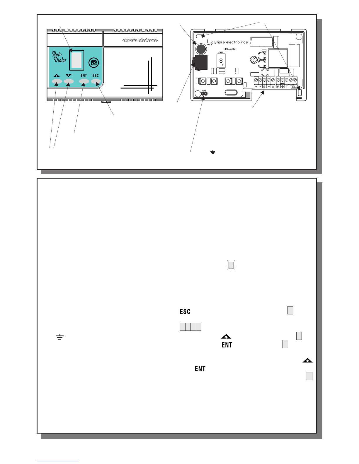
Na v i gati o n thro u gh
th e m e nu
En t e r Butt o n
Ac c e pts cu r rent s e lect i on
Es c a pe But t on
Us e d f or ent e ring t h e sett i ngs me n u
Di s p lay
Mo u n ting h o les
Mi c r opho n e
Ea r p hone p l ug
Ac c e ss cod e r eset j u mper
Ter m i n al Bl o c k s
+ 10 - 3 0 V DC
- 0V
B Me s s age  tr i gger i n put
- 0V
Á Me s s age A tr i gger i n put
R Te l e phon e l ine
Po w e r netw o rk ear t h wire
Ô Tel e pho n e l ine
TEL T e leph o ne set s
Figur e 1
-
P
000 0
-
0
-
921489000_09_005
Page 3
Page. 3 from 4
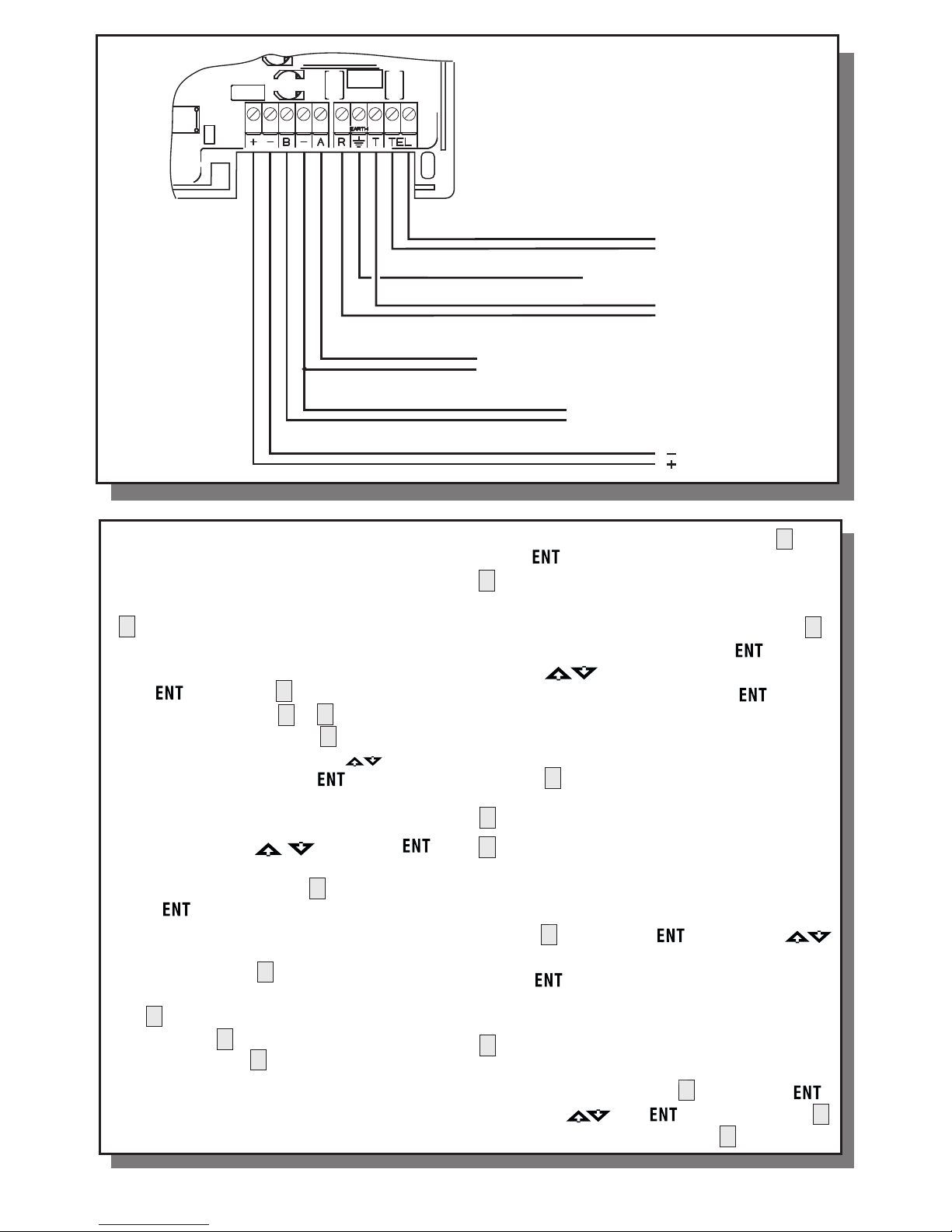
10 - 30V DC
from fire or alarm
panel
Connect to F_OUT
of fire panel
Connect to TEL.OPER (A and - or B and -)
or NC contact of alarm panel
Telephone LINE
Power network earth wire
To telephone sets
Figur e 2
the n the d evi c e dia ls th e num b ers
normally.
The full structure and the menu
operations are:
Entering phone numbers.
In this menu we can save up to 10
different numbers with 20 digits each.
With we select . Then we priority
of the number from to , with
maximum priority being .
We select the number with and we
save our selection with .
After the priority selection, we can
enter its digits one by one. We select
the number with and with
we save our selection. After entering
the last digit we select symbol and
press to save the phone number.
Then the number is saved and the
device returns in the priority selection
menu, at priority .
There also are some special symbols
as which stands for pause 0.8
seconds, th at st an ds fo r
asterisk (*) and that stands for sharp
(#).
If we want to delete an existing
phone number, we select its priority
and we replace the first digit with and
press .
Displaying saved phone numbers.
We can check which number is saved
in each memory position. We select
from the menu and press . With
keys we select the number’s
priority and we accept with . Then
the display starts displaying one-byone all the digits of the number. If
memory position is blank the display
shows . Then the device returns in
the priority selection menu, at position
.
Dialling check
In this menu we can dial any of the
numbers, in order to check the normal
connection of the device. To do this we
select and press . With keys
we select the number we want, and
press to accept. The device dials
the phone number and transmits the
recorded messages once.
Recording and listening messages.
We can Record up to two different
messages. We select and press .
With keys and we can select
to listen message A, or to listen
0
9
-
u
A
B
-
C
-
2
P
C
8
F
P
0
0
8
1
E
921489000_09_005
0
Page 4
Page. 4 from 4
message B.
In order to record a new message, we
select or respectively and press
. After a message is successfully
recorded, the message is replayed
on ce . In or de r to l i s t e n t o t he
messages, we must use the earphone
included with the package, that is
connected as shown in figure 1.
Tone or Pulse dialling selection
In th i s m en u we can se l e c t t he
preferred dialling method. When is
selected the device is set to pulse
dialling, and when is selected the
device is set to tone dialling. By default
this is set to Tone Dialling. Select pulse
dialling only if tone dialling is not
supported by your phone line or the line
is ISDN type.
Alarm operation setting
Selecting and we can configure
the settings referred to the operation of
the device when triggered from input A
or B.
If we select and then all the
st or ed nu mb er s wil l be dia ll ed
sequentially for as many times as the
pre-adjusted (2,3,4 etc). In the end of
the alarm the device starts dialling the
stored numbers for one time.
If we select and then in alarm
condition and after the end of it , the
de vi ce st ar ts d i a l l i n g t he st or ed
numbers for one time. If the alarm
co nt in ue s t he n th e de vi ce is
conti guously dialling all the stored
numbers.
If we select and , then the
device is dialling the stored numbers
for one time only, even when the alarm
condition continues.
Th e fact ory d efa ult s ett i ng for
dialler is set to .
Re-Dial Setting
We can set how many times every
number will be dialled. This can be
done by selecting and , and then
with from to and . The
factory default setting is .
Message re-play setting
We can set how many times a message
will be played in each call. This can be
done by selecting and , and then
with
From to and . The factory
default setting is .
Setting the access code
We can change the 4 digit access code
from the factory default , and set
the preferred one. From the main menu
we select and . Then with
and we set each digit of the new
access code.
Exiting the main menu
By selecting and the device
exits the main menu and gets in idle
mode.
Resetting access code
If we want to set the access code back
to factory setting( ) we have to
remove the power from the dialer, and
then place the jumper on pins Cn1
(image 1) located at the bottom left part
of t he p ri nte d cir cui t boa rd, and
connect the device back to power. The
display will show and after a while it
will turn off. Then the dialer will go back
to idle state with the default access
code. Then we can remove the jumper.
A
1
A
B
G
U
1
9
L
A
E
P
P
E
F
921489000_09_005
U
F
F
2
9
2
E
E
000 0
H
H
000 0
C
 Loading...