

Page 1
BURGLAR
ALARM PANEL
BS-468
Page 2

11-4-2017 2 921468001_09_015
Contents
1. Description ......................................................................................................................................... 3
2. Instructions for the user ................................................................................................................... 4
2.1Basic operations ............................................................................................................................. 4
Complete system. ............................................................................................................................................. 4
Split system. .................................................................................................................................................... 4
2.2 Armed system indication ............................................................................................................... 5
2.3 Advanced operations ..................................................................................................................... 5
2.4 Main User menu ............................................................................................................................ 7
3. Installation instructions .................................................................................................................. 12
3.1. Quick installation guide .............................................................................................................. 12
3.2. Connections ............................................................................................................................... 15
Connecting the battery and the mains power supply .................................................................................... 15
Keyboard connections .................................................................................................................................. 15
Siren connections ......................................................................................................................................... 16
Zone connections ......................................................................................................................................... 18
Smoke and heat detector connections ......................................................................................................... 19
3.3. Programming via the keyboard .................................................................................................. 20
Programming how the passwords function ................................................................................................... 21
General settings ........................................................................................................................................... 22
Automatic arming-disarming ......................................................................................................................... 23
Zone Programming ................................ ................................ ....................................................................... 24
Output programming ..................................................................................................................................... 26
Programming the general parameters of the system .................................................................................... 26
Programming the PSTN BS-465 telephone dialer ........................................................................................ 27
Programming the GSM BS-464 telephone dialer .......................................................................................... 28
3.4. Resetting to factory default passwords ...................................................................................... 31
3.5. Programming from the computer ............................................................................................... 32
Connection function ................................ ................................ ...................................................................... 33
Programming the panel ................................................................................................................................ 35
Zone settings ................................................................................................................................................ 37
Password settings ........................................................................................................................................ 38
Events ........................................................................................................................................................... 40
Timer settings ............................................................................................................................................... 41
Output settings ............................................................................................................................................. 42
New file ......................................................................................................................................................... 43
Open file ....................................................................................................................................................... 43
I - OLYMPIA APPLICATION ......................................................................................................................... 44
4. Technical Characteristics ............................................................................................................... 45
4.1. Peripheral device consumption chart ......................................................................................... 46
4.2. Information regarding the installation ......................................................................................... 47
Page 3
11-4-2017 3 921468001_09_015
1. Description
The BS-468 is an 8 zone burglar alarm panel. Using the special expansion card BS-469 it can be
expanded to 16 zones. For its operation, at least one BS-466 keyboard is required. Up-to 8 keyboards
can be connected to the panel. Each keyboard has an additional zone for connecting magnetic
contacts (zones 17–24). The main board of the panel has ports for connecting a RF-468 remote
control receiver and an automatic telephone dialer. On the telephone dialer port you can connect a
BS-465 wired PSTN telephone dialer or a BS-464 wireless GSM telephone dialer.
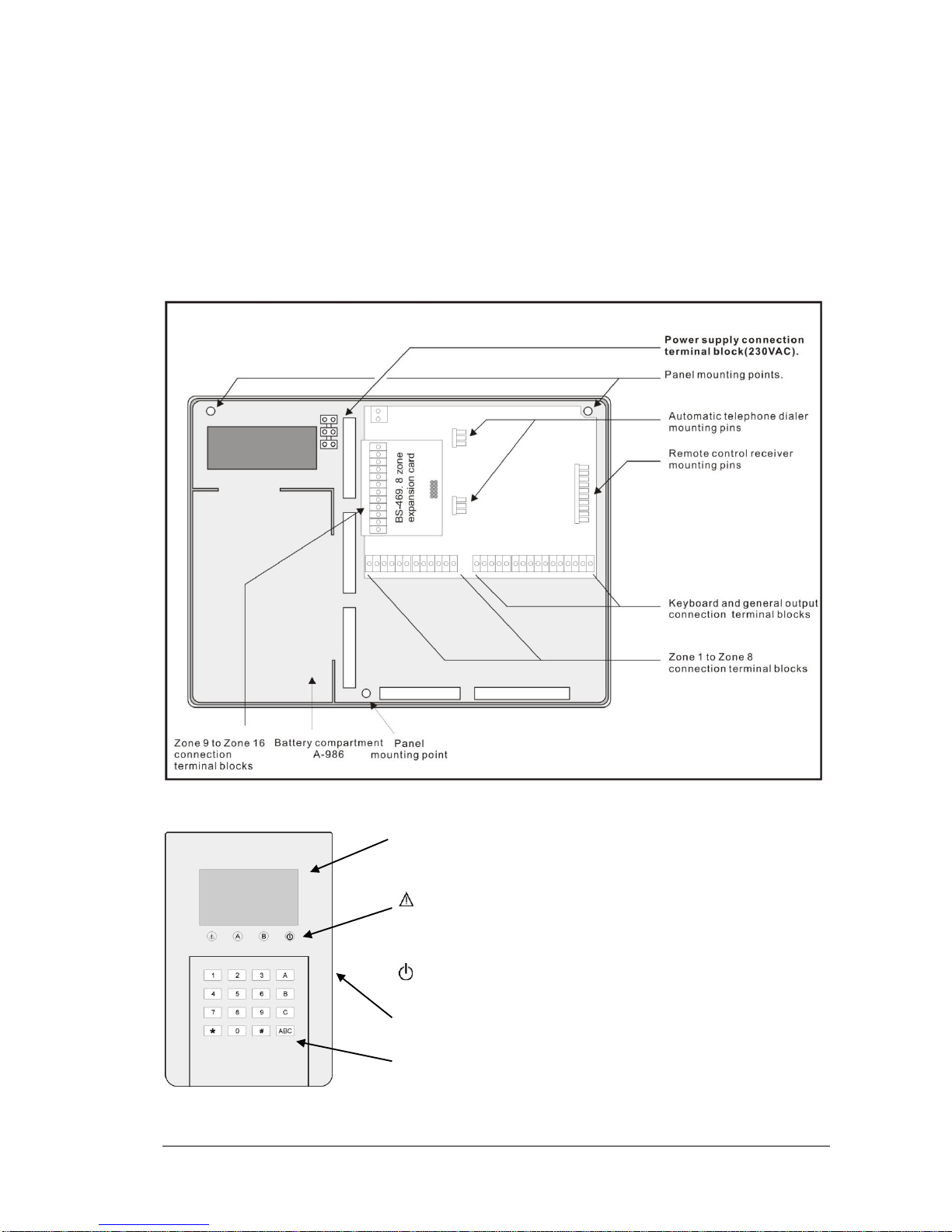
The diagram below shows the interior of the panel and the keyboard.
Οθόνη υγρού κρυστάλλου
USB port for programming
Indication LEDs
Lit means that there is an error, blinking means that there
is an alarm
Α System fully armed
Β System partially armed
The power is connected
Control keypad
Liquid crystal display
Page 4

11-4-2017 4 921468001_09_015
2. Instructions for the user
2.1Basic operations
The panel has 1 main code (master) which by default is set to [1 2 3 4] and up-to 50 user codes which
by default are not programmed. The system can operate with two different modes. Depending on the
mode of operation, the arm and disarm operations differ.
Complete system. In this case the system arms and disarms altogether
The arming can be done by using the master code or one of the user codes. The arming of the
system can also be done by simply pressing the ABC key during the installation if the option «one key
arming» has been selected.
The disarming can be done by entering the master code or one of the user codes.
Split system. In this case the system operates as three independent subsystems. You can arm
and disarm the whole system or each subsystem independent from the others.
The arming of all the system can be done by using the master code or one of the user codes that
have been programmed for general arming. The arming of the system can also be done by simply
pressing the ABC key if during the programming the option «one key programming» has been
selected.
The disarming of the system can be done by using the master code or one of the user code that
have been programmed for general disarming.
The individual arming of the subsystems Α,Β,C can be done by pressing one of the user codes
that have been programmed to arm each subsystem. The arming can also be done by pressing one of
the Α, Β or C keys if during the programming «one key arming» has been selected. The arming of one
subsystem does not affect the status (armed-disarmed) of the other subsystems.
The individual disarming of the subsystems Α,Β,C can be done by pressing one of the user codes
that have been programmed to disarm each subsystem. The arming of one subsystem does not affect
the status (armed-disarmed) of the other subsystems.
If during the arming procedure a zone is active then the keyboard show the message:
Which means that on zone 5(kitchen) a window has been left open.
If we press (#) the arm command is canceled.
If we press (*) or close the kitchen window we see:
This message is shown for 1 second and immediately the arming
process starts.
SYSTEM CAN NOT ARM
ZONE 05
KITCHEN
*: BYPASS ZONE
#: CANCEL
ZONES BYPASSED
READY TO ARM
Page 5
11-4-2017 5 921468001_09_015
2.2 Armed system indication
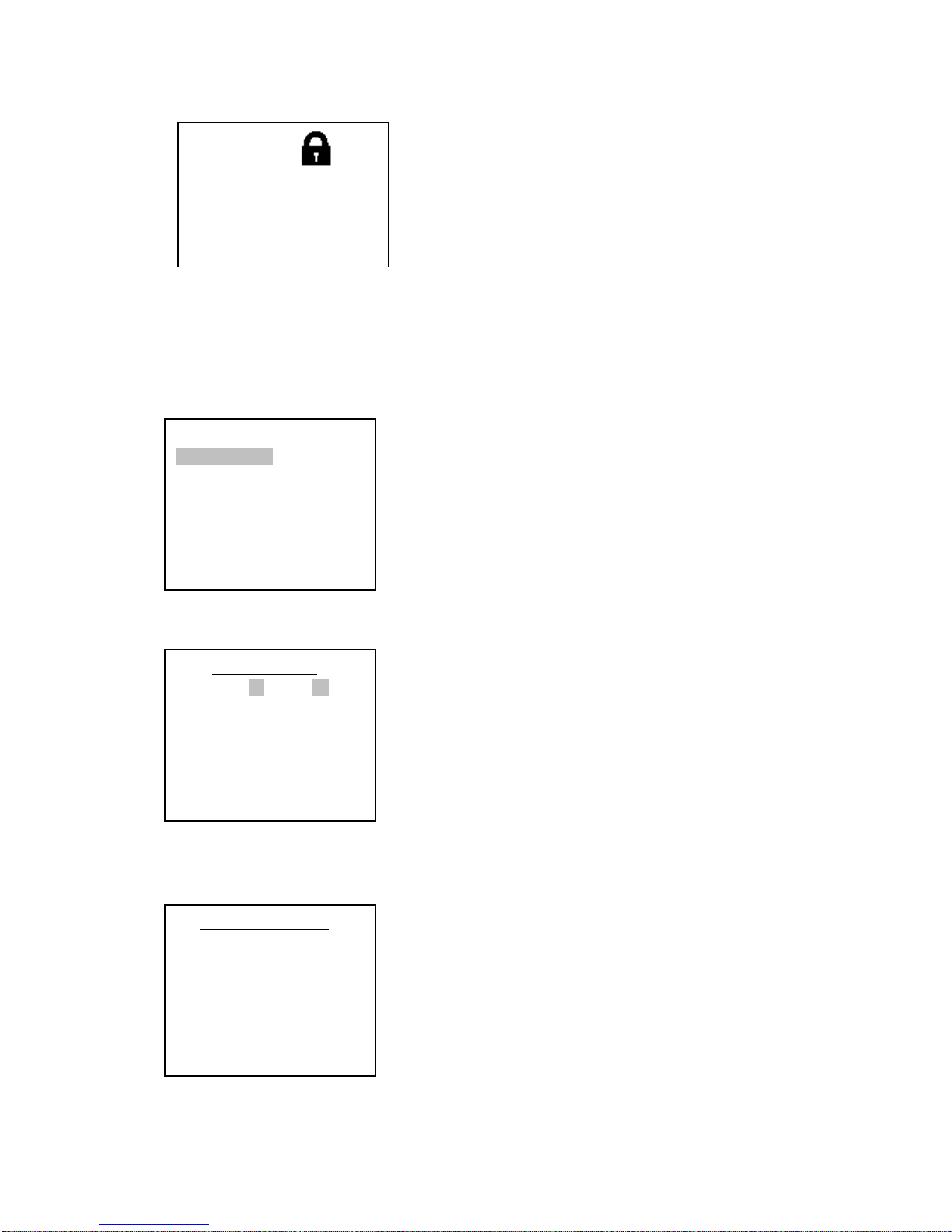
When the system is armed then next to the clock, instead of the
Olympia electronics logo there is a lock symbol. Next to the lock
symbol we can see which sections are armed. In this example we
can see that the system is partially armed because only the C
section is armed. If the system was fully armed then the symbols
Α, Β, C would be displayed. When the system is disarmed then
the lock is removed and the Olympia electronics logo is
displayed.
2.3 Advanced operations
Pressing the key (*) the display shows:
Using the up and down keys (keys 2 and 8) we can move the
cursor upwards or downward, using the key (*) we can make the
required selection or using the (#) we can go one level backward
or cancel a selection.
Selecting «BYPASS ZONES» we see:
Here we can select which zones are disabled (will not be armed)
during the next arming of the system. For example, if we enter 04
and then immediately 07, this means that the next time the system
is armed, zones 4 and 7 will be disabled. If a zone blinks, this
means that it is preventing the system from arming. If it is
blackened then this means that it is disabled. If it is blinking and
blackened then this means that it is disabled but would prevent the
panel from arming if it was not disabled.
Selecting «ZONES CONDITION»:
Here we can test the good operation of the zones and the devices
connected to them. For examples, if a magnetic contact of a
window is connected to zone 4 and the window opens then the
message of the display from «ALL ZONES OK» will be erased and
the indication 04 will start to blink. As soon as the window is closed
the screen will display the previous message «ALL ZONES OK»
With this method we can test the good operation of all the detectors
and magnetic contacts.
For the selection « MASTER OR TECH MENU » you will find information in the section Main User
Menu one page 7.
MENU
BYPASS ZONES
ZONES CONDITIONS
MASTER OR TECH MENU
ALL EVENTS
MANUAL OUTPUTS CHECK
INFORMATION
____ BYPASS ZONES ____
04 07
_____________________
CHOOSE FROM 01-24
BYPASS: --
___ZONES CONDITION ___
ALL ZONES OK
C
Page 6
11-4-2017 6 921468001_09_015
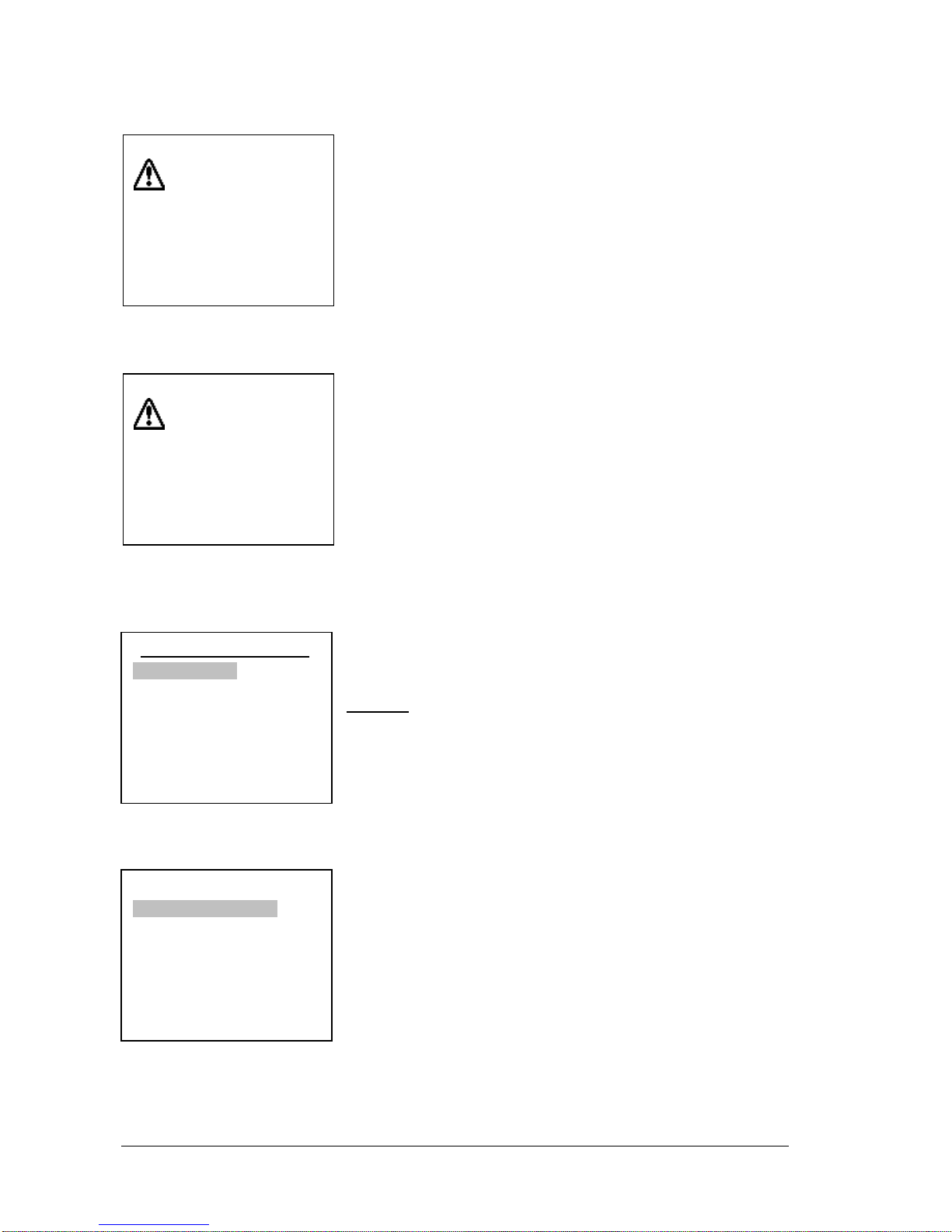
Selecting «LAST ALARMS» we can view the alarms that were registered during the last arming of the
system. The display will be like the one below:
This means that an alarm was registered for zone 8 which is a
TAMPER zone (24 hour operation). The alarm was issued on 12:20
on 07 March 2012 and that is the first of 3 events.
Using the up and down arrows (2 and 8) we can view all the
registered alarm events.
Selecting «ALL EVENTS» we can view all the events which are registered in memory. The display will
be like the one below:
This means that an error event was registered for zone1 at 12:20
on 07 March 2012. It also informs us this is the 70th event of a total
to 70. With the up and down arrow keys (2 and 8) we can see all
the registered events.
The event memory has a capacity of 250 events and once filled will
erase the oldest. The events that are registered are errors, alarms,
user and technician menu access as well as the arming and
disarming of the system. The main user and the technician can
both erase the events memory using there respective menus.
Selecting «MANUAL OUTPUTS CHECK» we can see:
With the up and down arrow keys we can select the required option
and by pressing (*) we can see or we can change the state of the
output Ρ1, Ρ2, Ρ3, RELAY.
Warning. In order for an output to be able to change state from this
selection it must be programmed as «ON OFF MANUAL». When an
output changes state, the device connected to it is activated. A
manual change of the output sets the output to a permanent
condition which can only change by manually changing the output
again. It is suggested to use this selection with caution and only if
we want to manually control a connected device.
Selecting «INFORMATION» we can see:
With the up and down arrow keys we can make the selection and
by pressing the (*) key we can view the keyboard firmware version,
the panel firmware version, the information regarding the technician
supporting the system and the signal level (If a GSM is connected)
The selection «TECHNICIAN INFO» by default has information of
Olympia electronics.
TAMPER
ZONE 08
ΖΟΝΕ 8
07/03/12 12:20
001/003
ERROR
ZONE 01
ΖΟΝΕ 1
07/03/12 12:20
070/070
_MANUAL OUTPUTS CHECK _
CHANGE OUTPUT
OUTPUTS STATUS
______INFORMATION______
KEYBOARD SOFT VERS.
PANEL SOFT VERSION
TECHNICIAN INFO
SIGNAL LEVEL
Page 7
11-4-2017 7 921468001_09_015
CHANGE PASSWORD
SELECT FROM 01-50
- -
If “SIGNAL LEVEL” is selected and a GSM module is not connected
then the following message is shown.
2.4 Main User menu
Via the user menu we can change critical parameters of the system. To enter the user menu we must
know the master code.
Pressing the key (*), selecting «MASTER OR TECH MENU» and pressing again (*) we see:
By default, the master code is: 1234 but can be changed by
the user.
Type the master code to enter the user menu. The display shows:
With the «EVENTS» selection we can delete the events memory.
If we make this selection, the system requests a confirmation and
then erases all the events from the events memory.
With the «CODES» option we can alter the master code or user
codes or delete the user codes.
Selecting «CODES» and pressing (*) we see:
With the «CHANGE PASSWORD» selection we can create or
alter the user passwords. Up to 50 user passwords can be set and
are named code01, code02 up to code50. By default all user
passwords are inactive and it is up to the user in cooperation with
the technician to create them during the installation phase. The
technician will program the permissions for each code and the
user will give the four digits.
If we want to alter a password we select «CHANGE PASSWORD»,
press the key (*) and the display shows:
INSERT CODE
TO ENTER MENU
- - - -
__ MASTER MENU __
EVENTS
CODES
SETTINGS
TIMERS
_______CODES________
CHANGE PASSWORD
DELETE PASSWORD
CHANGE MAIN PASSWORD
NO GSM CONNECTED
PRESS ‘#’ TO RETURN
Page 8
11-4-2017 8 921468001_09_015
We enter the number of the password (i.e. 03) which we want to change and we see:
After entering the 4 new digits the system request us to repeat them. We enter again the 4 digits. If the
codes match then the change is made and the display shows the relative message.
If we want to delete a password, from the CODES menu select «DELETE PASSWORD». The screen
changes and we enter the number of the password that we want to delete. After that the system
deletes the password.
If we want to change the main password, from the CODES menu select «CHANGE MAIN
PASSWORD». By pressing the key (*) we see:
After entering the 4 new digits of the password we are
prompted to repeat the process. We enter again the 4 digits
and if they match we the previous entry then the display
shows the relative message and the change is made. To
enter the user menu we must use the new main password.
Warning!! By default the main password is 1 2 3 4. The user
must change this password immediately after the installation
of the system is finished.
Selecting from the MASTER MENU the option «SETTINGS» we see:
With the selection «ARM WITH TECH. CODE» we select if the
system will be armed or disarmed with the password of the
technician. By default this selection is set to NO.
03:CHANGE PASSWORD
- - - -
CHANGE MAIN PASSWORD
- - - -
______SETTINGS_______
ARM WITH TECH. CODE
DAY OF WEEK SETTING
DATE SETTING
TIME SETTING
IDLE BACKLIGHT LEVEL
IDLE BACKLIGHT MODE
BUZZER SETTING
Page 9
11-4-2017 9 921468001_09_015
With the selection «CHANGE DAY OF WEEK» we see:
With the up and down cursor key we select the required day and
by using the (*) key we make the selection.
With the selection «DATE SETTING» we see:
We enter first the day then the date and last the 2 last digits
of the year.
With the selection «TIME SETTING» we see:
We enter the hour (in 24 hour format) and then the minutes.
After a while the display shows a confirmation message.
It is important that the above settings are made correctly in
order to have accurate logging of the events where the time
and date are also logged along with the event.
With the selection «IDLE BACKLIGHT LEVEL» we select the brightness of the display when the
system is idle. By default the selection is set to 40%.
With the selection «IDLE BACKLIGHT MODE» we can select when the illumination of the display is
active. There are 3 options:
ALWAYS OFF. The display is illuminated by pressing of any key. The brightness level drops
to the idle backlight level after 1 minute.
ONLY WHEN DISARMED. The display is always illuminated when the system is disarmed.
When the system is armed the display illumination turns ON after a key is pressed and the
brightness level drops after 12 minute.
ALWAYS ON (DEFAULT). The illumination of the display is always ON. This selection
reduces the autonomy of the system in case of power failure.
With the «BUZZER SETTING» we select if the buzzer is sounded during all the events or only during
alarm events. The default setting is «SOUNDS TO ALL EVENTS».
_ CHANGE DAY OF WEEK _
MONDAY
TUESDAY
WEDNESDAY
THURSDAY
FRIDAY
SATURDAY
SUNDAY
CHANGE DATE
^
02/05/12
CHANGE TIME
^
09:17
Page 10
11-4-2017 10 921468001_09_015
Finally the MASTER MENU has the option «TIMERS». With this selection we can program up to 10
automatic arming or disarming procedures of all or part of the system. Selecting «TIMERS» we see
the display below. If the «CHANGE TIMER» is selected then this means that the timer is active. If the
«DELETE TIMER» is highlighted then this means that the timer is
inactive. The inactive timer always has a default time of 12:00.
The selection «CHANGE TIMER» is also used to create a procedure.
By selecting «CHANGE TIMER» using the up down arrow keys and pressing the (*) key we see:
Select the number of the timer that we want to alter or create and we see:
Enter the hours and minutes that we want the timer to activate and we see:
Select the day of the week that we want the timer to operate. If we
select «EVERY DAY» it will operate all of the days.
______TIMERS________
CHANGE TIMER
DELETE TIMER
CHANGE TIMER
SELECT FROM 01-10
- -
CHANGE TIME
^
12 :00
_ SET DAY OF WEEK _
EVERY DAY
MONDAY
TUESDAY
WEDNESDAY
THURSDAY
FRIDAY
Page 11
11-4-2017 11 921468001_09_015
By pressing the (*) key we see:
We make the required selection of the function that we want the
timer to do and press the key (*). The system confirms the
selection.
The event memory logs the arming or disarming of the system but
also shows that the event has been launched by a timer.
Finally if we want to delete a timer select «DELETE TIMER» and the screen shows:
Enter the number of the timer that we want to delete.
_ CHANGE ACTION _
ARM ALL
DISARM ALL
ARM Α
ARM Β
ARM C
DISARM Α
DISARM Β
DISARM C
DELETE TIMER
SELECT FROM 01-10
- -
Page 12

11-4-2017 12 921468001_09_015
3. Installation instructions
3.1. Quick installation guide
By default the panel has the following settings
Zone 1 : Zone with delay section Α
Zone 2 : Zone with delay section Β
Ζone 3 : Zone without delay section Β
Ζone 4 : Zone without delay section Β
Ζone 5 : Zone without delay section Α
Ζone 6 : Zone without delay section Α
Ζone 7 : Zone without delay section Α
Zone 8 : TAMPER zone
Zone 17 (keyboard 1) : Zone with delay section Α
Entry time : 20 seconds
Exit time : 45 seconds
Siren time : 1 minute
Additional exit time : 20 seconds
We can return to this state if we select «RESET DEFAULTS» from the programming menu. With
these settings we can do a simple and typical installation in a residence with an additional perimeter
alarm.
Connect to zone1 or to the zone of the keyboard the magnetic contact of the main entrance door. On
zone 2 the radars that monitor the entrance area. On zones 3 and 4 the rest of the radars and on
zones 5 to 7 the magnetic contacts that we require to give an immediate alarm. Finally on zone 8
connect the TAMPER of the external siren. We can either arm section A (perimeter alarm) when we
are in the house or all the system (ABC).
For connection methods see the next section «CONNECTION».
There are 6 pre-made programs that you can select via the technician menu and from the selection
«SYSTEM» and « LOAD PANEL SETTING » (see page 26). These are:
1. Zone 1 : Zone with delay section Α with bell sound
Zone 2 : Zone with delay section Α
Zone 3 : Zone without delay section Α
Zone 4 : Zone without delay section Α
Zone 5 : Silent section Α
Zone 6 : Panic section Α
Zone 7 : Fire section Α
Zone 8 : TAMPER zone
Zone 17 (keyboard 1) : Zone with delay section A
This program is suitable for a store. Connect to zone 1 or to the zone of the keyboard the entrance
magnetic contact. On zone 2 the radars that monitor the entrance area. On zone 3 and zone 4 the rest
of the radars and the magnetic contacts that we require to give an immediate alarm. On zone 6
connect a manual button for a silent alarm in case of threat, on zone 6 the panic button and on zone 7
the fire detectors. Finally on zone 8 connect the TAMPER of the external siren.
Page 13

11-4-2017 13 921468001_09_015
All zones are on the same section and the system arms and disarms all together. On zone 1 the
magnetic trap activated the bell on the keyboard to warn us that the door has opened.
2. Zone 1 : Zone with delay section Α
Zone 2 : Zone with delay section Β
Zone 3 : Zone without delay section Β
Zone 4 : Zone without delay section C
Zone 5 : Zone without delay section C
Zone 6 : Zone without delay section Α
Zone 7 : Zone without delay section Α
Zone 8 : TAMPER zone
Zone 17 (keyboard 1) : Zone with delay section Α
This pre-made program is suitable for a 2-story house. Connect to zone 1 or to the zone of the
keyboard the entrance magnetic contact. On zone 2 the radars that monitor the entrance area. On
zone 3 the remaining radars of the ground level floor, on zones 4 and 5 the radars of the first floor and
on zones 6 and 7 the magnetic contacts of the ground floor and the first floor respectively. Finally
connect the TAMPER of the external siren to zone 8. By arming section A we have a parametric
alarm, with the arming of section A and B we have a parametric alarm with the simultaneous operation
of the ground floor radar detectors and if we arm sections ABC we have full operation of the system.
3. Zone 1 : Zone with delay section Α With bell sound
Zone 2 : Zone with delay section Α
Zone 3 : Zone without delay section Α
Zone 4 : Zone with delay section B
Zone 5 : Zone with delay section B
Zone 6 : Zone without delay section B
Zone 7 : Zone without delay section B
Zone 8 : TAMPER Zone
Zone 17 (keyboard 1) : Zone with delay section Α
This pre-made program is suitable for a house-store combination using the same alarm panel and the
same siren. Connect on zone1 or on the keyboard zone the magnetic contacts of the store entrance.
On zone 2 the radars that monitor the entrance area of the store. On zone 3 the remaining radars or
magnetic contacts of the store. On zone 4 the magnetic contact of the house entrance, on zone 5 the
radars that monitor the entrance of the house and on zones 6 and 7 the remaining radars and
magnetic contacts of the house. Finally on zone 8 connect the TAMPER of the external siren. By
arming section A we have an alarm system only for the store, by arming section B we have an alarm
system only for the house and by arming section ABC we have an full alarm system for both the store
and house.
4. Zone 1 : Zone with delay section Α
Zone 2 : Zone without delay section Α
Zone 3 : Zone without delay section Α
Zone 4 : Zone without delay section Α
Zone 5 : Zone without delay section Α
Zone 6 : Zone with delay section B
Zone 7 : Zone without delay section B
Zone 8 : TAMPER zone
Zone 17 (keyboard 1) : Zone with delay section Α
Page 14

11-4-2017 14 921468001_09_015
This program is identical to the previous program but with more zones for the store.
Zone 1 : Zone with delay section Α
Zone 2 : Zone with delay section Α
Zone 3 : Zone without delay section Α
Zone 4 : Zone without delay section Α
Zone 5 : Silent section Α
Zone 6 : Panic section Α
Zone 7 : Fire section Α
Zone 8 : TAMPER Zone
Zone 9 : Zone without delay section Α
Zone 10 : Zone without delay section Α
Zone 11 : Zone with delay section B
Zone 12 : Zone with delay section B
Zone 13 : Zone without delay section B
Zone 14 : Zone without delay section B
Zone 15 : Zone without delay section B
Zone 16 : Zone without delay section B
Zone 17 (keyboard 1) : Zone with delay section Α
This pre-made program is suitable for a big store with section A and B.
5. Zone 1 : Zone with delay section Α
Zone 2 : Zone with delay section Α
Zone 3 : Zone without delay section Α
Zone 4 : Zone without delay section Α
Zone 5 : Zone without delay section Α
Zone 6 : Zone with delay section B
Zone 7 : Zone with delay section B
Zone 8 : TAMPER Zone
Zone 9 : Zone without delay section B
Zone 10 : Zone without delay section B
Zone 11 : Zone without delay section B
Zone 12 : Zone with delay section C
Zone 13 : Zone with delay section C
Zone 14 : Zone without delay section C
Zone 15 : Zone without delay section C
Zone 16 : Zone without delay section C
Zone 17 (keyboard 1) : Zone with delay section Α
This pre-made program is suitable for a big store with section A, B and C.
Page 15
11-4-2017 15 921468001_09_015
3.2. Connections
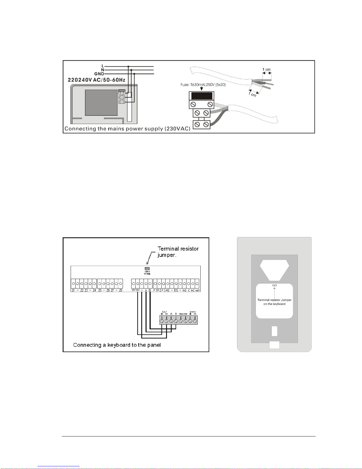
Connecting the battery and the mains power supply
For the battery there are two cables, red and black for connecting to the positive and negative pole
respectively.
Keyboard connections
To facilitate the installation, the keyboard has two parts, the base and the main body. The base is the
part that must be mounted to the wall. It contains only the connections terminals and a small alignment
vial that is used to correctly mount the base. After connecting the cables, the main body is fastened to
the base. A screw on the bottom side does not permit accidental removing of the main body from the
base.
To connect the panel to the keyboard of keyboards use the terminals 2V, -, A και Β. Respective
terminals are also found on the keyboard. The connection is a typical RS-485 connection and requires
a terminal resistor on the two outmost devices.
Connecting a keyboard to the panel. The jumper for the terminal resistor must be placed in order to
make contact with the 2 pins (activated terminal resistors).
Page 16

11-4-2017 16 921468001_09_015
Connecting 8 keyboards to the panel. The cables must be connected in such a way that will permit the
connection of the device one after the other. No terminal should contain 3 cables or more. The
jumpers of the terminal resistors must be placed only on the two outer most devices. On all the other
devices is should be removed or left in a open position.
This same connection can be used if we want to connect 2 to 7 keyboards.
Siren connections
Page 17

11-4-2017 17 921468001_09_015
For connecting the autonomous siren type BS-413 up-to 7 cables are required.
On the terminals (+) και (-) connect the voltage (AS), (-) which charges the siren.
When we supply the (ST) with 12V the siren and the beacon are activated. It is connected to the P1
contact of the panel which is programmed to provide 12V during an alarm and 0V during the idle state.
When the (SE) terminal is connected to (-) it prohibits the siren to operate. This cable is connected to
a (-) terminal of the panel during the installation procedure or any other time that the cover of the siren
must be removed (i.e. during a battery change). In normal operation the cable must be removed from
the (-) terminal of the panel.
When the (FL) terminal is supplied with 12V the beacon is activated. If it is connected to the terminal
P3 of the panel then the beacon will flash once for 2 seconds when the panel is armed and three times
(0.5 second duration) when the panel is disarmed.
The contacts (Τ1) and (Τ2) are the TAMPER contacts of the siren which are connected to a
respective zone on the panel which by default is zone 8.
To connect an internal siren BS-441, two cables are required. Connect the (ES) and (-) of the panel to
the respective (+) and (-) of the siren.
Each panel can accept up-to 2 external autonomous and 1 internal siren.
Page 18
11-4-2017 18 921468001_09_015
Zone connections
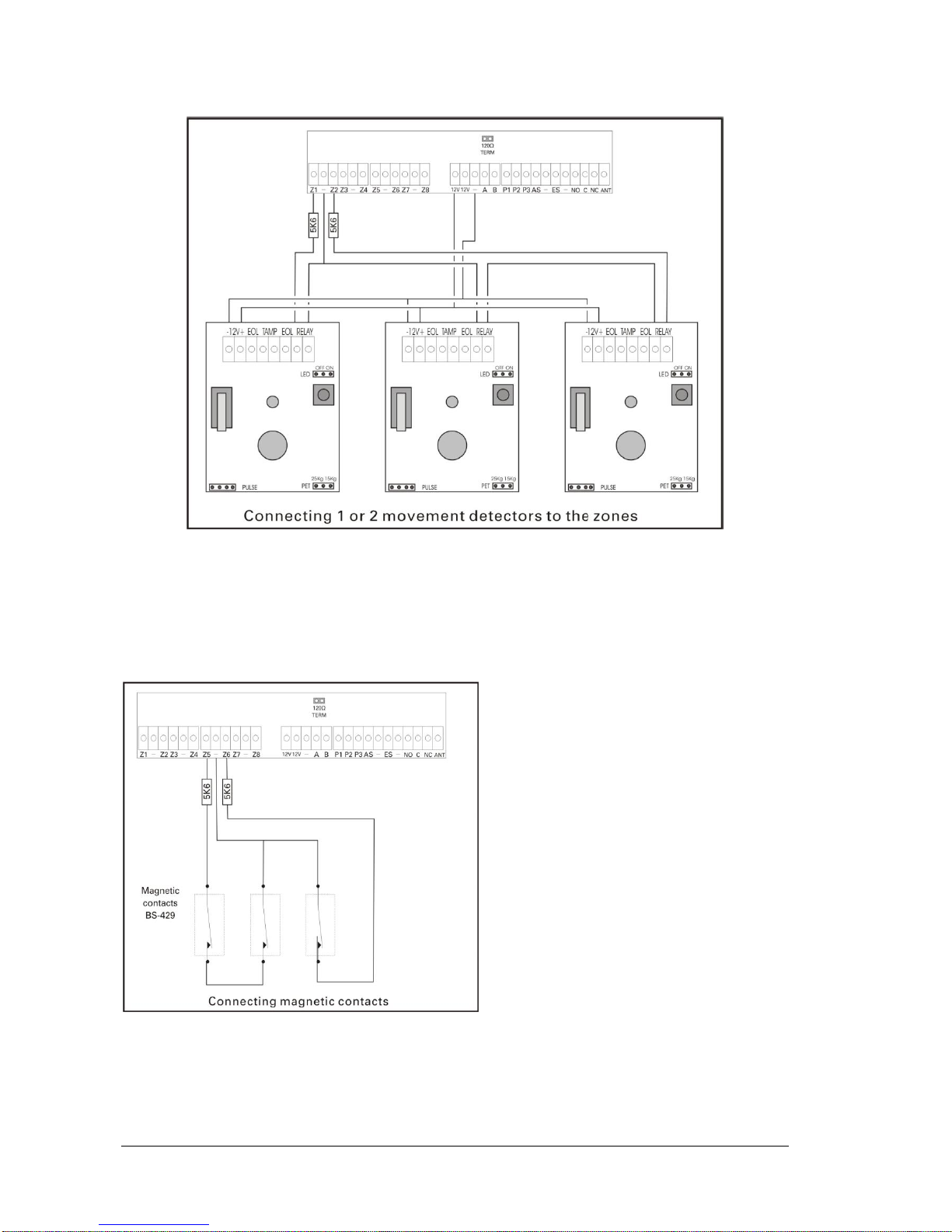
Connecting the panel with radars (infrared movement detectors, PIR) or other devices which require
power. For the connection, 4 cables are required (6 if the TAMPER is connected). The 2 cables are
connected to the (12V) and (-) of the panel and provide power to the respective terminals of all the
detectors. The other 2 cables connect in series the contacts RELAY (NC) of all the detectors of the
zone and the resistors found on the terminals of the panel. The diagram above provides examples for
connecting 1 or 2 detectors on the zones.For the connection of magnetic contacts or other devices
that do not require power only 2 cables are required.
These connect in series the contacts with the terminal resistors found on the zones of the panel. The
diagram above shows the connections with one or two magnetic contacts on the zones.
Page 19
11-4-2017 19 921468001_09_015
Smoke and heat detector connections
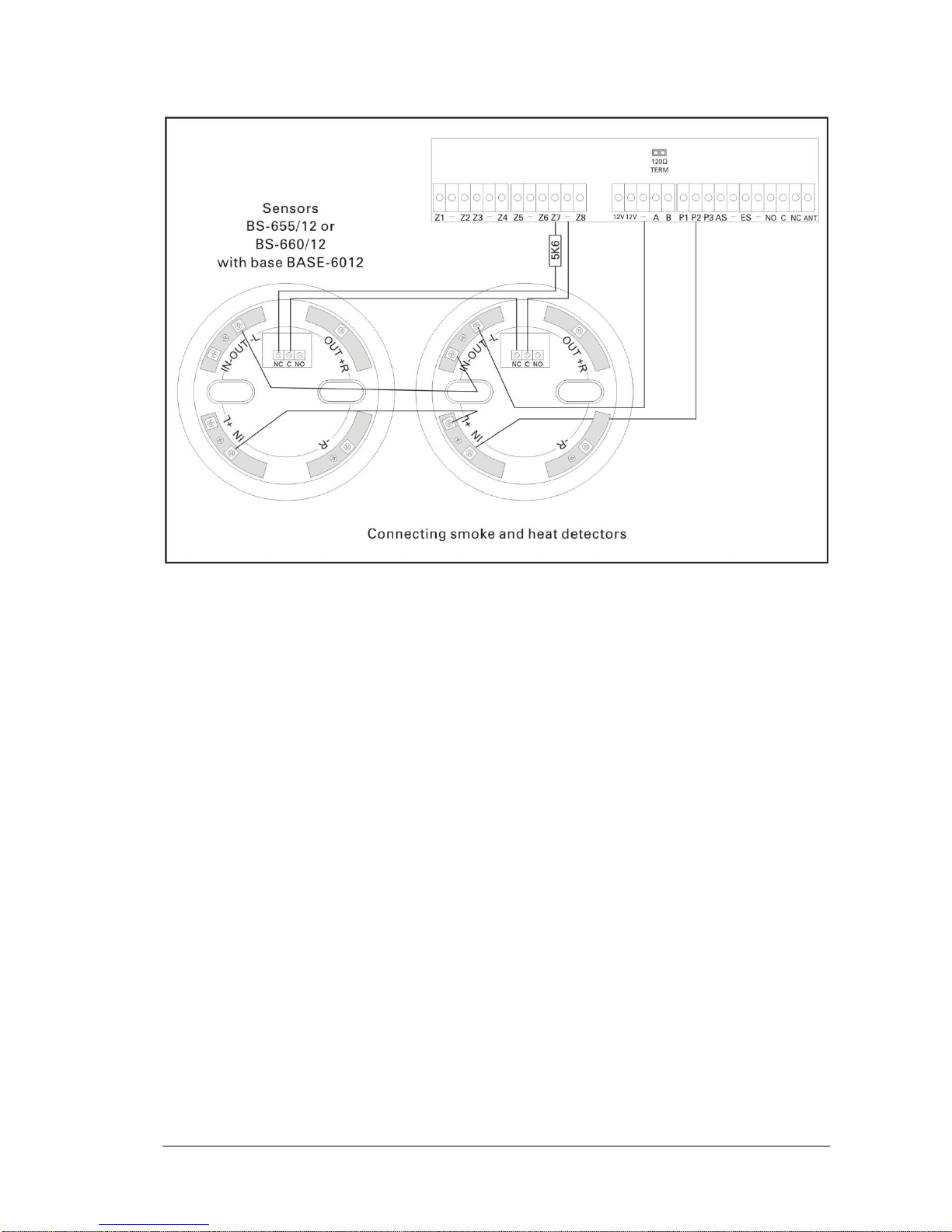
The connection of the fire detectors must be done to a zone which has been programmed as a
«FIRE» zone. The normally closed contacts of the relay on the base (NC,C) are connected in series
with the resistor of the zone of the panel.
The power to the base is done using (-) and the output Ρ2 which by default is programmed as «
SUPPLY FIRE DETECTOR ».
Page 20
11-4-2017 20 921468001_09_015
3.3. Programming via the keyboard
Let it be noted that when trying to change a setting in the user menu or the technician menu you can
view the current value of the setting. The only menus that do not offer the preview of default values
are the 2 menus «CALL ON» on the PSTN and GSM, as well as the 2 menus «EVENTS
NOTIFICATION» of the ARC (Alarm Receiving Center) of the PSTN and the GSM.
Also when a value is entered (i.e. entry time), and after the last digit is entered the value is stored
automatically without the need to press an additional key. If we do not reach the last digit of the value
and the ‘*’ is pressed then the value that is shown on the display is stored. There is always an
indication on the display that shows which digit is edited. This is shown with the symbol ‘^’ under the
current digit.
When the adjacent display is shown the system is in the process of an
important process which cannot be stopped by using the keyboard.
The process will finish and then the display will show the main menu.
If a problem occurs during the process then a relative message will be
shown before the return to the main menu.
Sometime a menu can contain content that cannot be shown in one
screen. In this case a scroll bar is shown and we can change screens using the up and down keys.
The scroll bar looks like the symbols below:
This shown that there is a next page from the current one.
This shows that there is a previous page than the current one.
This means that there is a previous and a next page than the current
one.
For entering a menu: While on the initial screen, press the key (*), and select with the up and down
keys (keys 2 and 8) « MASTER OR TECH MENU.» And by pressing again the key (*) we see:
The technician password by default is: 9999 but can be
changed by the technician that installs the panel.
INSERT CODE
TO ENTER MENU
- - - -
UPDATING DATA..
Page 21
11-4-2017 21 921468001_09_015
By entering the technician’s password we enter the technician menu and we see:
By selecting the «EVENTS» option we can erase the events log. If
we make this selection the system asks for a confirmation and
then erases the entire events log.
The «CODE» option permits us to change the technician’s
password and change the operation method of the user
passwords.
Programming how the passwords function
If after selecting «CODES» and pressing (*) we select «CHANGE PASSWORD» we see:
Via this option we can select the way that each user
password functions.
We enter the number of the password that we want to
program or to change the password function and we see:
For each code we must make one of the following selections which
mean:
«OFF». The password is present but does not have any function.
«NATURAL ARM DISARM.». The password arms and disarms the
panel. Making this selection by pressing the (*) we must select the
section that the password affects. We select A, B, C or ABC. By
default all passwords are set for «NATURAL ARM DISARM» and for
section ABC.
“PANIC 24 HOURS”. This password gives a panic alarm whichever state the panel is.
SET. The password arms (doe not disarm) the panel immediately. Making this selection and pressing
the (*) we must select the section that is affected by the password. We can select A, B, C or ABC.
UNSET. The password disarms (does not arms) the panel immediately. Making this selection and
pressing the (*) we must select the section that is affected by the password. We can select A, B, C or
ABC.
SET WITH DELAY EXTRA. The password arms only (does not disarm) the panel but with an exit
delay. Making this selection and pressing the (*) we must select the section that is affected by the
password. We can select A, B, C or ABC.
PG CONTROL. The password activates or deactivates one of the controllable outputs. Making this
selection and by pressing (*) we must select the output that the password affects. We can select Ρ1,
Ρ2, Ρ3 or RELAY.
__ TECHNICIAN MENU __
EVENTS
CODES
SETTINGS
TIMERS
ZONES
OUTPUTS
SYSTEM
PSTN
GSM
CHANGE PASSWORD
SELECT FROM 01-50
- -
__ CODE REACTION __
OFF
NATURAL ARM DISARM.
PANIC 24 HOURS
SET
UNSET
SET WITH DELAY EXTRA.
PG CONTROL
SILENT ALARM
Page 22

11-4-2017 22 921468001_09_015
SILENT ALARM. The code activates the silent alarm. When the user enters the code, the panel will
disarm (if the panel is armed) and will remain in idle state (the siren will not sound, and the alarm leds
will be off). The panel will call or send a message via BS-465 or BS-464 to the selected telephone
numbers.
General settings
From the «TECHNICIAN MENU» if we select «SETTINGS» we see:
From this menu we can adjust all the general settings of the panel.
«ENTRANCE TIME». This is the time that the zones delay to give an
alarm. This is valid only for zones that have been programmed as
zones with delay. By pressing (*) a new screen is shown and the
current entrance delay is shown (30) in seconds. Enter the new time
(05-99 2 digits are mandatory) i.e. 0 and 9 for 9 seconds. The
system stores the value and returns to the menu «SETTINGS».
«EXIT TIME». Is the time from when the arming password is entered
until the actual arming of the system. Pressing (*) reveals a new
screen where the current exit time is shown. By default it is 45
seconds. We enter the new required exit time with 2 digit numbers
(05-99 2 digits are mandatory) i.e. 6 and 0 for 60 seconds. The
system stores the value and returns to the menu «SETTINGS».
«ALARM TIME». Is the time that the siren is sounded. This time
counts from the instance that all activation devices have stopped
activating the panel. Select 1 or 2 minutes, press (*). The system
stores the value and returns to the menu «SETTINGS».
«EXTRA EXIT TIME.» Is the time that is added to the exit time when the system is activated with a
password which has an additional delay or by a zone with delay.
«SECTIONS EXIT TIME». With this selection if we will have an exit time for the sections (A, B, C). We
must reply YES or NO for each subsection.
«ENTRANCE DELAY BEEPS.» Select if the built-in buzzer will sound during the entry time.
«EXIT DELAY BEEPS.» Select if the built-in buzzer will sound during the exit time.
«BEEP PARTIALLY ARMED.» Select if the built-in buzzer will sound during the exit time in case of a
partial arming of the system (section arming Α, Β or C).
«BEEP PARTIALLY ARMED» Select if the system can be armed without a password, with the use of
the keys A. B. C. ABC. The selection only affects the arming, for the disarming a password is always
required.
«ARMED SYS INDICATORS». We have 2 selections «OFF» or «ON». It places in the according state
the 4 indication LEDs when the panel is armed. The indicators are lit when the panel is disarmed.
«IDLE BACKLIGHT MODE» This option regards the illumination of the display and the keypads during
the idle state of the system. The idle state is the state where there is not alarm and no key has been
pressed for 30 seconds. We have 3 options. ALWAYS OFF, ONLY WHEN DISARMED which means
off in an armed system and on in a disarmed system and ALWAYS ON.
«DOUBLE BUTTON PANIC» We select if a panic signal alarm can be issued from the keyboard. If we
select YES and we simultaneous press for two seconds the keys C and ABC then a panel alarm will
be produced.
«RECORD OUTPUTS EVENT». We select if the state of the outputs will be logged as individual
events (Ρ1, Ρ2, Ρ3 and RELAY).
______SETTINGS______
ENTRANCE TIME
EXIT TIME
ALARM TIME
EXTRA EXIT TIME
SECTIONS EXIT TIME
ENTRANCE DELAY BEEPS
EXIT DELAY BEEPS
BEEP PARTIALLY ARMED
ARM WITHOUT CODE
ARMED SYS INDICATORS
IDLE BACKLIGHT MODE
DOUBLE BUTTON PANIC
RECORD OUTPUTS EVENT
AUTOMATIC BYPASS
REMOTECONTROL ACTION
ANNUAL CHECK WARNING
Page 23
11-4-2017 23 921468001_09_015
«AUTOMATIC BYPASS» By selecting YES, all zones that have be programmed with bypass
capabilities (see zone programming), if during the arming are active (i.e. an open window) are
bypassed automatically by the system. When the zones are deactivated (i.e. the window has closed)
they are automatically activated. If we select NO then if there are active zones during the arming
procedure the system will request a bypass confirmation for each active zone.
«REMOTE CONTROL ACTION» We select the operation mode of the remote control (if available)
between ARM-DISARM, PANIC, ALL FUNCTIONS and DEACTIVATION. When ‘’ALL FUNCTIONS‘’
is selected, we can perform arming, disarming, panic alarm and silent alarm. For wireless operation
use the RF-468 remote control receiver and RF-467 remote control transmitter.
«ANNUAL CHECK WARNING» We select if the system will issue a reminder signal after
1 year of operation to reminder the user for the annual technical inspection.
Automatic arming-disarming
The next selection in the technician menu is the selection «TIMERS». Via this selection we can
program up-to 10 automatic arming or disarming of the whole or partial system. Selecting «TIMERS»
we see:
The selection «CHANGE TIMER» is also used to create a
procedure. When this menu is selected it is significant if the cursor
goes to change timer or delete timer, see timers on the user
menu.
Using the up and down keys and select «CHANGE TIMER» and after pressing the (*) we see:
We select the number of the timer which we want to change or create and we see:
______TIMERS________
CHANGE TIMER
DELETE TIMER
CHANGE TIMER
SELECT FROM 01-10
- -
CHANGE TIME
^
12: 00
Page 24
11-4-2017 24 921468001_09_015
We enter the hours and minutes that we want the timer to activate and we see:
We select the day of the week when we want the timer to activate.
If we select «EVERY DAY» the timer will activate all of the days.
By pressing the (*) key we see:
We make the required selection of the function that we want the
timer to do and press the key (*). The system confirms the
selection.
The event memory logs the arming or disarming of the system but
also shows that the event has been launched by a timer.
Finally if we want to delete a timer select «DELETE TIMER» and we see:
Enter the number of the timer that we want tot delete.
Zone Programming
The next option in the TECHNICIANS MENU is «ZONES» via which we can adjust the parameters of
the zones. When the selection is made we see the name of the zone for 2 seconds and then:
We select the required zone and after a while we can see in
sequence all the menus where we can program the zone. In
every menu the cursor highlights the current setting. First we
have the menu «ZONE MODE» which gives us the options
below:
«DISABLE OFF». The zone does not function and cannot
issue and alarm or fault signal. In this state are all the zone
that are not physically installed on the system (i.e zones 0916 if there in no expansion card). Usually we set to this state
all the zones that are not used.
_ CHANGE DAY OF WEEK _
EVERY DAY
MONDAY
TUESDAY
WEDNESDAY
THURSDAY
FRIDAY
DELETE TIMER
SELECT FROM 01-10
- -
CHOOSE ZONE
SELECT FROM ΑΠΟ 01-24
- -
_ CHANGE DAY OF WEEK _
ARM ALL
DISARM ALL
ARM Α
ARM Β
ARM C
DISARM Α
DISARM Β
DISARM C
Page 25

11-4-2017 25 921468001_09_015
«ZONE WITH DELAY». The zone will issue an alarm after an entrance delay. This selection is used
for the magnetic contacts that are used for the main entrance and also for the radar the will detect the
user before he reaches the panel to disarm it.
«"ZONE WITHOUT DELAY». The zone will issue an immediate alarm. This selection is used for radar
detector and magnetic contact that are used in other areas.
«PANIC». This zone will issue an immediate alarm even if the panel is disarmed. It will also produce a
panic alarm message if a telephone dialer is installed. It can be used on zones that have a panic
button.
«FIRE». This zone will issue an immediate alarm even if the panel is disarmed. It will also produce a
fire alarm message if a telephone dialer is installed. It can be used on zones that have smoke and
heat detectors.
«SILENT». The zone will issue an immediate silent alarm. It will activate the telephone dialer if
installed and not the sirens. It can be used in zones that have a panic button that can manually be
operate by a human that is been threatened.
«ZONE NEXT DELAY.». This zone if activated will issue an alarm signal after an exit delay plus the
additional exit delay.
«SET SECTION». When this zone is activated it will arm the whole system or a section of it. It can be
used to arm the panel via some other system such as a BMS or fire alarm system. The zone must be
connected with the close relay contact of the other system.
«UNSET SECTION». When this zone is activated it will disarm the whole system or a section of it. It
can be used to arm the panel via some other system such as a BMS or fire alarm system. The zone
must be connected with the close relay contact of the other system.
«SET UNSET SECTION.». When this zone is activated it will change the state of the panel or a
section of it from armed to disarmed and visa versa. It can be used to arm the panel via some other
system such as a BMS or fire alarm system. The zone must be connected with the close relay contact
of the other system.
«PG CONTROL». This zone for all the time that it is active will also activate the output that it controls.
«TAMPER». This zone will issue an immediate alarm even if the panel is disarmed. It can be used as
a zone for connecting the TAMPER outputs of the external siren or the other devices.
«RADAR 2 PULSES». This is a special zone setting used for avoiding false alarms. Only radars must
be connected to this zone. With the panel armed it operates with the following way:
If the panel receives the first alarm signal from the zone it waits for 5 minutes. If during this wait it
receives a second signal it issues an immediate alarm. If during the 5 minute wait a second signal is
not received then the first signal is considered to be a false alarm and is discarded.
After selecting the zone mode we must select the section (A,B,C). If we want to operate the panel as
a whole system then this selection is important.
The next setting is «ZONE BELL». If we select YES when the panel is armed and the zone is
activated then the keyboard buzzer will sound. This function can be used for example to warn us that
the door of a store has opened by connecting its magnetic trap to this zone.
With the next selection, «BYPASS» we select if a zone can be bypassed either manually or
automatically. By default this setting is set to YES for all zones. Select NO only for critical zones, (i.e.
zone with magnetic contact used for protecting a safe) so that the system cannot be armed when the
specific zone is active.
The «FORCED ARM» setting has 2 different operation modes. If we select YES then if the zone
during the arm process is active (i.e. open window) the system will be armed without regarding this
Page 26

11-4-2017 26 921468001_09_015
zone. The zone is regarded again by the system when it stops being active ( i.e. when the window
closes). If we select NO and the zone during the arming process is active (i.e. open window) and the
automatic bypass has been selected, the system will warn us that the arming is not possible.
For the last three setting if we select ZONE MODE the panel will automatically select the correct
setting. If no special setting are require then it is good practice to no alter these.
Output programming
The next setting of the technician menu is «OUTPUT». Via this
setting we can program how each of the outputs Ρ1, Ρ2, Ρ3 and
RELAY will operate. When an output is activated we mean that it
has 12V or the relay has been activated. When an output has been
deactivated it has 0V and the relay is in the idle state.
If we press (*) select the output and press again the (*) key we are
presented with the following options:
«DISABLE OFF». The output does not operate
«LIKE SIREN». Activates the external siren (via the START terminal) with positive logic. It has 0V in
the idle state and 12V in alarm. By default this is how the P1 output is programmed.
«ON ALARM». It is activated when we have an alarm on the zone which has been programmed like:
ZONE WITH DELAY.
ZONE WITHOUT DELAY.
ZONE NEXT DELAY.
TAMPER
RADAR 2 PULSES.
«ON FIRE». It is activated when we have an alarm from a FIRE zone.
«ON PANIC». It is activated when we have an alarm from a PANIC zone.
«ON FAULT». It is activated when we have any fault.
«ON ARM». It is activated when the panel is armed.
«FLASH». It produces 3 short pulses during the arming of the panel and one long pulse during the
disarming. It can be connected to the FLASH or FL of the external siren. It is useful if the system is
control by remote control. By default the output P3 is programmed with the function.
«ON OFF MANUAL». It is activated manually by the keyboard of by a zone that has been
programmed as PG CONTROL. By default the output RELAY is programmed like this.
«AC STATUS». It is activated in the event of an AC power supply failure.
«SUPPLY FIRE DETECTOR». It is suitable for powering smoke and heat detectors. It has a
permanent voltage of 12V which is disrupted for 5 seconds after every disarming. By default this is
how the output P2 has been programmed.
«ΟΝ SILENT ALARM». It is activated when an alarm has been issued by the SILENT zone.
Programming the general parameters of the system
The next selection in the technician menu is «SYSTEM». Via this selection we can adjust various
parameters f the system:
«DEVICE ADDRESS». Change the address of the keyboard. By default each keyboard BS-466 has
address 2. If we only have one keyboard there is no reason to change the address. If we have more
that 1 keyboard, each keyboard must have its own address in order to be acknowledged by the panel.
«SCAN KEYBOARDS». If we press (*) the system scans for all connected keyboards and shows then
on the display.
«SCAN EXTENSIONS». If automatically detects the expansion cards. It must be used every time that
we connect one of the expansion cards such as the zone expansion card, GSM telephone dialer or
PSTN telephone dialer.
__ OUTPUT SELECTION __
P1
P2
P3
RELAY
Page 27
11-4-2017 27 921468001_09_015
«RESET DEFAULTS». It reset all settings to factory defaults (see
page 13).
«LOAD PANEL SETTINGS». The memory of the panel contains 6
groups of preset settings that can be used for simple and usual
installations. With this selection we can automatically adjust the
system to use one of these presets. For a complete description of
these preset groups see page 13.
«ANNUAL CHECK DONE». It erases the annual inspection counter. If
we press (*) the annual inspection warning will be shown again after
365 days.
Programming the PSTN BS-465 telephone dialer
The entry to the PSTN menu is allowed only if the system has registered a PSTN telephone dialer
(see the menu «SYSTEM» «SCAN EXTENSIONS»).
If the entry to the PSTN menu is prohibited then the adjacent display
is show.
If the entry to the PSTN menu is allowed then the adjacent screen is
shown.
«CALLING NUMBERS». The option permits us to store into memory a telephone number and give it
the properties that we require.
We can store up to 6 telephone numbers that can be either a
mobile or land line numbers, local or international. Using this
menu we select the number of the telephone that we want to
alter. Select from 1 to 6
After selecting the number of the phone that we want to alter the following screen is shown:
Here we select to which events the current telephone number is
called. The options available are more than the one shown on the
display. More option can be viewed only with the computer software
PC-468 that accompanies the panel BS-468.
Due to the fact that in this menu not all option are shown, the cursor
does not highlight the current option but always the top most.
____SYSTEM____
DEVICE ADDRESS.
SCAN KEYBOARDS
SCAN EXTENSIONS
RESET DEFAULTS
LOAD PANEL SETTING
ANNUAL CHECK DONE
NO PSTN CONNECTED
PRESS ‘#’ TO RETURN
____ PSTN_______
CALLING NUMBERS
INCOM. CALL REACTION
TELEPHONE LINE CHECK
ALARM RECEIV. CENTER
PHONE SERIAL NUMBER.
SELECT FROM 1 TO 6
_____ CALL ON ______
ALARM AND FAULT
ALARM ONLY
FAULT ONLY
PANIC AND FIRE ONLY
TAMPER ONLY
MAINS ABSEND ONLY
Page 28
11-4-2017 28 921468001_09_015
After making the required selection it is time to enter the actual telephone number.
Due to the fact that the ‘*’ and or ‘#’ can be part of the number, the
storage is done using the ‘Α’ key, the cancellation is done using ‘Β’
key and finally with the ‘C’ we can clear the currently displayed
number (it is filled with dashes) and the cursor is moved to the first
digit.
Be noted that in order for the pressing of the keys ‘Α’, ‘Β’ and ‘C’ to be valid they must be pressed for
at least 1 second.
«INCOM. CALL REACTION». This setting permits us to adjust how
the PSTN dialer acts during an incoming call. The options available
are «DO NOT ANSWER» or « AFTER 15 SEC.» as well as after
10,15,20,25,30,or 40 seconds. There is also an option to respond
after a second call has been received. It is obvious that if the fist
option is selected then the PSTN dialler cannot accept remote
commands for telephone calls. Also, regarding the other selections,
the call will be answered.
In the «ARC STATUS» we select if the ARC(Alarm Receive Center)
is activated or deactivated, in the «ARC PHONE NUMBER» we can
enter the telephone number of the ARC and with the PANEL ID, 0-9
& B-F we can enter the ID of the alarm panel, using the numbers 0
to 9 and the letters from B to F. Next in the menu is «EVENTS
NOTIFICATION» were we can select from which events the ARC
will be informed by during the «COMM. TEST). We can adjust the
panel to not do a communication test with the ARC or to doa test
every 4,8, or 24 hours. Finally with the option «COMM. TEST(WAIT)
we can manually establish a communication between the panel and
the ARC and see the results in a few seconds
Programming the GSM BS-464 telephone dialer
The entry to the GSM menu is allowed only if the system has registered a GSM telephone dialer (see
the menu «SYSTEM» «SCAN EXTENSIONS»).
If the entry to the GSM menu is prohibited then the adjacent display is
show.
If the entry to the GSM menu is allowed then the adjacent screen is
shown.
NO GSM CONNECTED
PRESS ‘#’ TO RETURN
____ GSM ____
CALLING NUMBERS
INCOM. CALL REACTION
ENTER SIM CARD PIN
REMOTE ACCESS ENABLE
LINE NUMBER ENTRY
6977123456-----------
Α: CONFIRM
Β: CANCEL
C: CLEAR ALL
INCOM. CALL REACTION
DO NOT ANSWER
AFTER 5 SEC.
AFTER 10 SEC.
AFTER 15 SEC.
AFTER 20 SEC.
AFTER 25 SEC.
AFTER 30 SEC.
AFTER 40 SEC.
ALARM RECEIV. CENTER
ARC STATUS
ARC PHONE NUMBER
PANEL ID, 0-9 & B-F
EVENTS NOTIFICATION
COMMUNICATION CHECK
COMM. TEST(WAIT)
Page 29
11-4-2017 29 921468001_09_015
«CALLING NUMBERS». The option permits us to store into memory a telephone number and give it
the properties that we require.
We can store up to 6 telephone numbers that can be mobile or
land line numbers, local or international. Using this menu we
select the number of the telephone that we want to alter. Select
from 1 to 6
After selecting the number of the phone that we want to alter the following screen is shown:
Here we can select if during the selected events the GSM will call and send
an SMS to the telephone number, will only call the telephone number or will
only send an SMS to the telephone number. It is advised to use SMS
notification and not phone calling since charging can be verified easily (a
phone call can be transferred to an automatic telephone dialer instead of the
phone)Also the use of SMS is simpler that the use of phone calling.
After selecting one of the above options the following screen is shown:
This selection is valid only if we have enabled remote access in the initial
GSM menu. Here we select if the current number can send remote
commands to the GSM or not.
After this option has been set the following screen is shown:
Here we select to which events the current telephone number is called. The
options available are more than the one shown on the display. More option
can be viewed only with the computer software PC-468 that accompanies
the panel BS-468.
Due to the fact that in this menu not all option are shown, the cursor does
not highlight the current option but always the top most.
After making the required selection it is time to enter the actual telephone number.
Due to the fact that the ‘*’ and or ‘#’ can be part of the number, the storage
is done using the ‘Α’ key, the cancellation is done using ‘Β’ key and finally
with the ‘C’ we can clear the currently displayed number (it is filled with
dashes) and the cursor is moved to the first digit.
Be noted that in order for the pressing of the keys ‘Α’, ‘Β’ and ‘C’ to be
valid they must be pressed for at least 1 second.
_____ SMS CALL _____
CALL AND SMS
CALL ONLY
SMS ONLY
REMOTE ACCESS ENABLE
YES
NO
_____ CALL ON ______
ALL EVENTS
ALARM ONLY
FAULT ONLY
PANIC AND FIRE ONLY
ON ARM
MAINS ABSEND
ALARM AND FAULT
LINE NUMBER ENTRY
6977123456-------
Α: CONFIRM
Β: CANCEL
C: CLEAR ALL
PHONE SERIAL NUMBER.
SELECT FROM 1 TO 6
Page 30
11-4-2017 30 921468001_09_015
Also note that the local number are entered without the country code (i.e. 6977123456), whereas the
international number are entered with the country codes (i.e. 00506977123456).
This was the menu «CALLING NUMBERS» in the initial GSM menu. The remain 3 menu are
described below:
«INCOM. CALL REACTION». This setting permits us to adjust how the GSM dialer acts during an
incoming call. The options available are «DO NOT ANSWER» ή « AFTER 15 SEC.». It is obvious that
if the fist option is selected then the GSM dialer cannot accept remote commands for telephone calls,
even if the calling telephone number has been programmed to send remote commands. Also,
regarding the second option, the 15 seconds is not and absoluter value. Small 1 second differences
can be observed for this time value
«ENTER SIM CARD PIN». Here we see the options «ENTER PIN» and «CARD HAS NO PIN ». The
second option is for the case that the installed card does not have a PIN number.
If the installed card has a PIN number (first option), then this PIN number must entered in this menu or
else the GSM will not be able to operate until a PIN is entered.
It is advised to use SIM cards with no PIN number. To
remove the PIN number for the SIM card ,remove the card
from the GSM unit (be sure that the GSM dialer is not
powered) and place it in a mobile phone. Use the phones
menus to remove the PIN number. Remove the card from
the phone and replace it in the socket of the GSM card.
Reinstall the GSM card on the panel BS-468. Please note
that the PIN code is requested twice. For the code to be
considered correct we must enter it correctly both times.
.
«REMOTE ACCESS ENABLE». With this option we select if the GSM will be able to accept remote
commands.
If «DEACTIVATED» is selected, then the GSM will not accept
commands from any telephone number.
If «ACTIVATED», is selected, the stored telephone number can send
commands to the GSM, only if the option “remote access” is activated
for this telephone number.
If «ACTIV BY UNKNOWN NUM» is selected then any telephone
number can issue commands to the GSM.
For more details information regarding the GSM card BS-464 (i.e remote access, SMS command
syntax) refer to the user manual of the BS-464.
ENTER SIM CARD PIN
REMOTE ACCESS ENABLE
DEACTIVATED
ACTIVATED
ACTIV BY UNKNOWN
NUM.
Page 31

11-4-2017 31 921468001_09_015
3.4. Resetting to factory default passwords
The main board of the panel contain 2 pins with the marking CODE RESET. With this we can reset the
passwords to the factory defaults by following the procedure below:
1. Connect the cable SERVICE of the siren to a (-) on the panel.
2. Isolate the mains power supply and disconnect the battery
3. Link the pins CODE RESET with the jumper.
4. Connect the mains power supply and the battery
5. Remove the jumper when the display of the keyboard lights
After this procedure the main master code is 1234 and the technician code is 9999 and all the user
codes are empty.
Page 32
11-4-2017 32 921468001_09_015
3.5. Programming from the computer
The programming of the panel can be done easily by using the special computer software PC-468 that
is provided free by Olympia Electronics. To connect the panel to the computer a simple mini-USB
cable is required. This is provided with the BS-468/KEYPAD as well as the newest version of the
software.
WARNING!!! The latest version of the software PC-468 is available in the following web address
http://www.olympia-electronics.gr/support_gr.asp
The pane must not be connected to the computer before installing the software.
The installation of the program is done automatically by inserting the CD in the drive or by running the
file BS-468setup.exe found in the installation CD. After the installation connect the USB cable to the
USB port of the BS-466 keyboard in order to establish a connection with the panel.
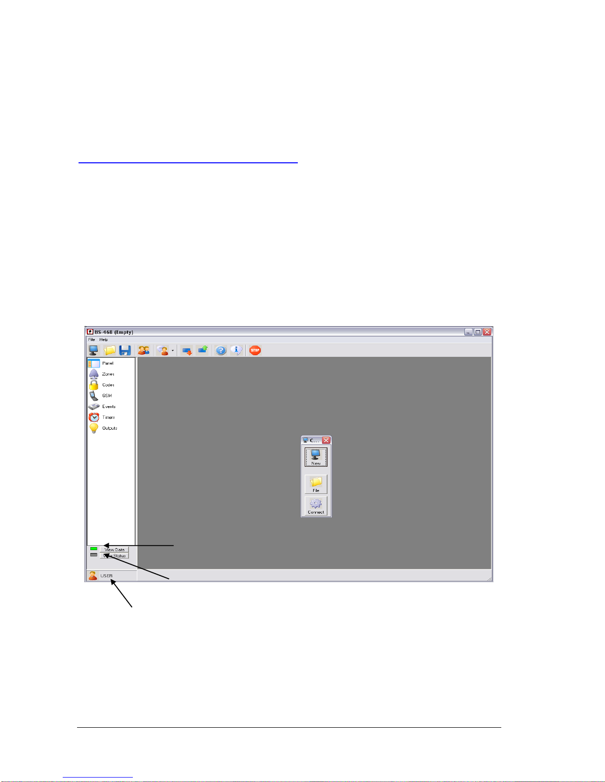
When the program starts we have 3 options:
1) New (to create a new file)
2) File ( to open or modify a file)
3) Connect ( establish a connection with the BS-468 panel)
Every time it lights there is a communication with the panel
Access lever Technician, User.
When green there is a connection and when red there in not
Page 33
11-4-2017 33 921468001_09_015
Connection function
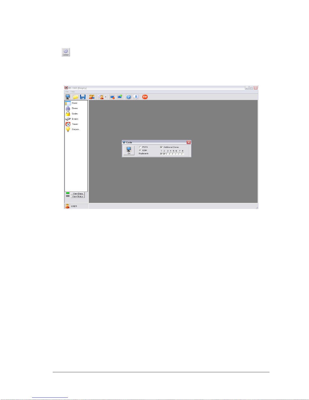
To establish a connection with the panel, connect the usb cable to the keyboard BS-466 and click on
the as shown in the screen above.
The indicators on the bottom left corner must be green.
After the connection is established the panel settings are shown. (below screen)
Next the connected devices and the keyboards are shown. Press OK to continue.
Page 34
11-4-2017 34 921468001_09_015
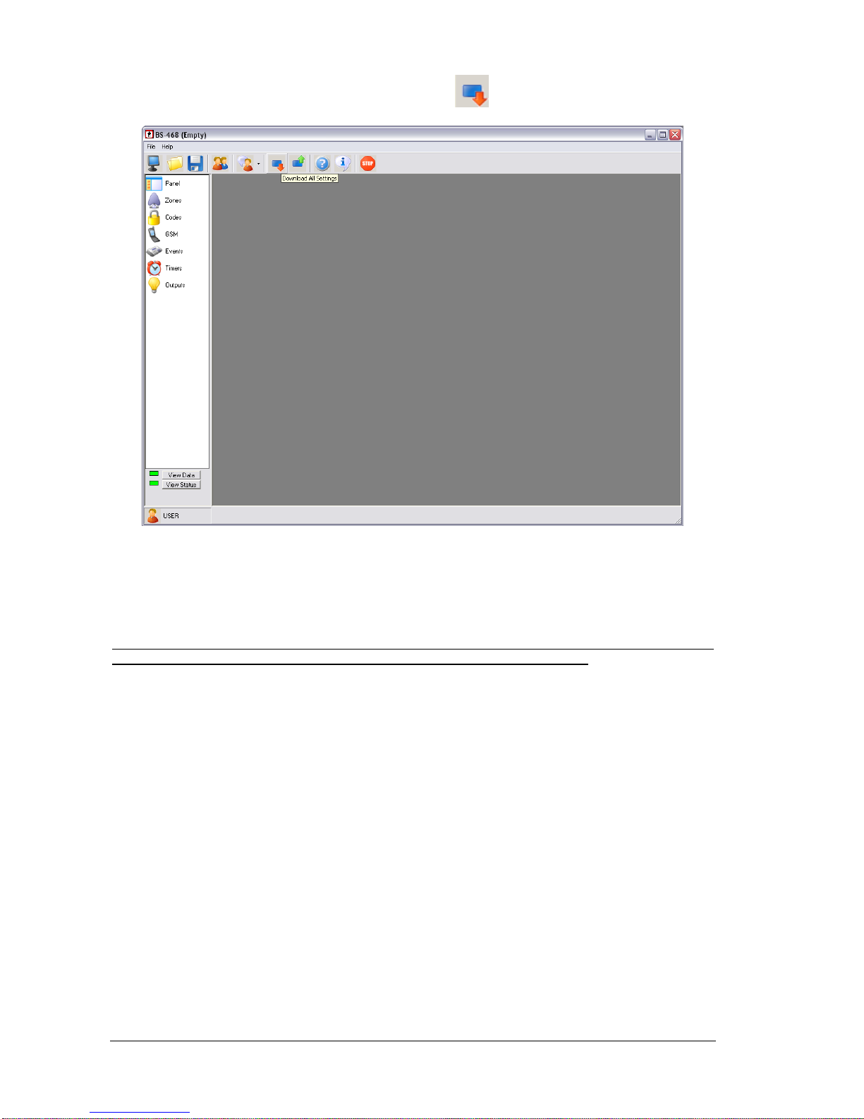
We can receive all the settings of the panel by clicking on , as shown below.
The panel requests a password for this operation. We must enter either the technician code ( 9 9 9 9 )
or the main user password ( 1 2 3 4 ) to receive all the settings of the panel.
Next we can set or view all the settings of the panel such as zones, passwords, events, timers and
outputs.
Be noted that depending on which password was entered, technician or main user the access level
changes and only the settings that correspond to the current level can be altered.
Page 35
11-4-2017 35 921468001_09_015
Programming the panel
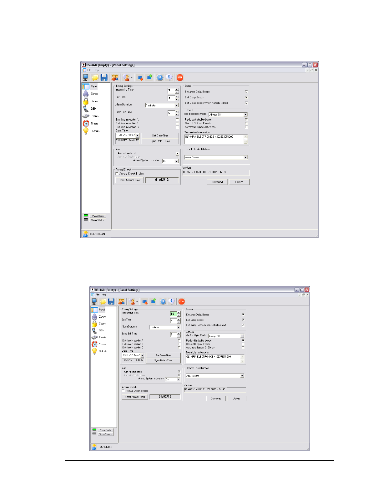
We can view or alter the settings of the panel.
The above settings can be altered only be using the keyboard but by using the software we have a
better visual perspective and the programming is easier.
Also by using the software we can easily synchronize the date and the time of the computer to that of
the panel by clicking on the corresponding button.
Page 36
11-4-2017 36 921468001_09_015
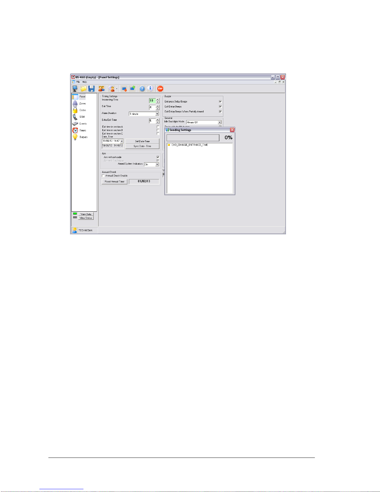
If for example we want to change the entrance time to 10 seconds press the up arrow next to the 7
second entrance time as shown below. We see that the entrance time 10 is highlighted. This means
that we have changed this setting but the have not been stored yet. By clicking on the button «Send»
a window is shown for sending the new settings to the panel. When the transfer has finished the
windows closes and the highlight is removed.
This procedure is adhered too for every change in the settings.
Page 37
11-4-2017 37 921468001_09_015
Zone settings
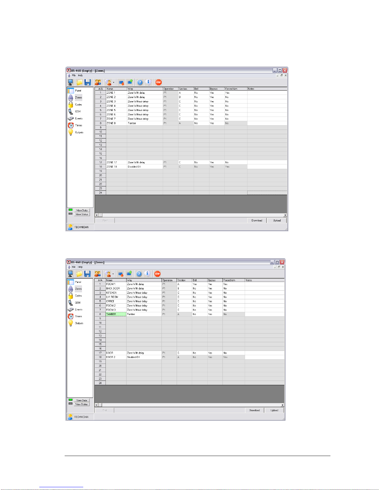
To set the zones of the panel we select the option «Zones». And a screen like the one below is
shown.
The technician can alter the operation of each zone whereas the main user can give a name to each
zone so it can be easily recognized.
The screen above shows how we can change the name of each zone.
Warning!! The name of the zone can change only by using the PC software.
Page 38
11-4-2017 38 921468001_09_015
Password settings
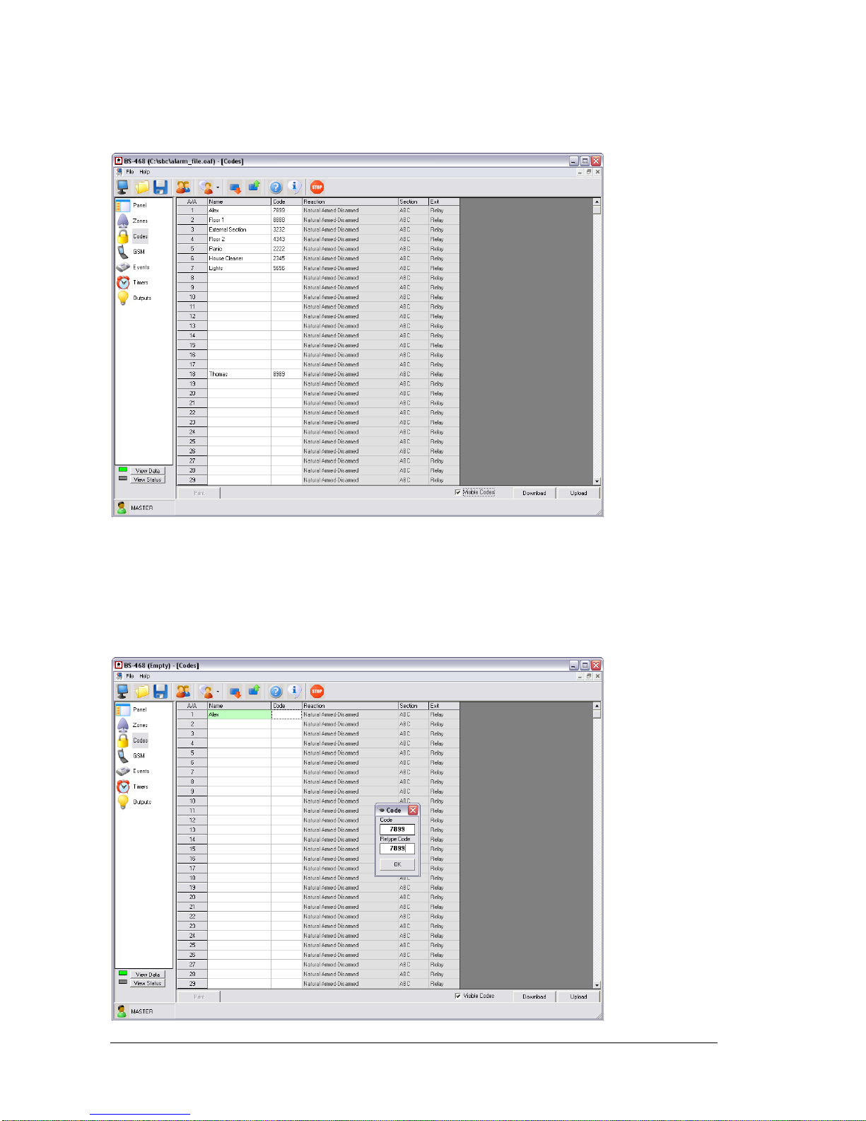
If the technician enters the password option he can change only the reaction, section and output as
shown in the screen below.
The technician can also make changes to the codes which can also be done from the BS-466
keyboard.
If the main user enters this option he can only change the name and the password.
The name of the password is not sent to the panel. It is used as information for the person
responsible.
Page 39
11-4-2017 39 921468001_09_015
When we enter a code it request for us to enter it 2 times in order to avoid errors.
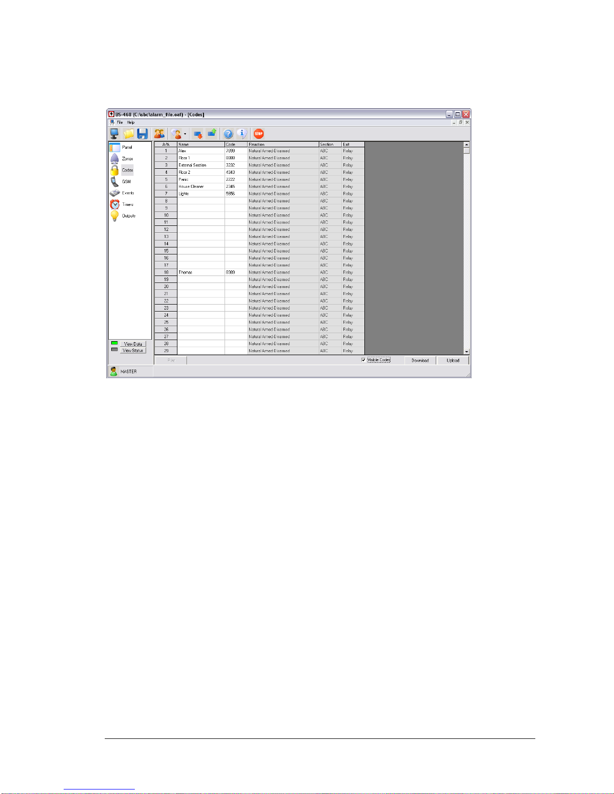
In the previous screen we a can see an option «Visible codes». With this option the main user can
later if the codes will be shown or if they will be in the form an asterix.
The screen above shows a typical system.
Page 40
11-4-2017 40 921468001_09_015
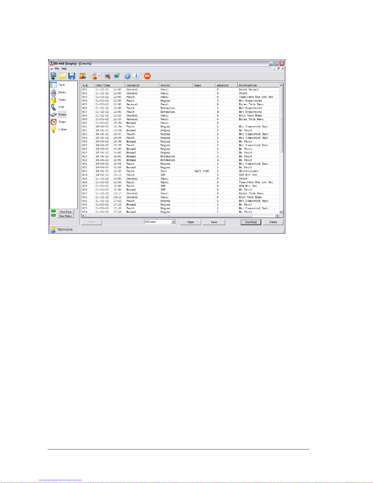
Events
We this option we can see all the events of the panel.
Clicking the button «Receive» to view all the events that have occurred
The columns shown are:
- Α/Α the number of the event
- Date and time of the event.
- Category. It can be an alarm, fault, general, normal, bypass, warning e.t.c.
- Source. From where the event came from. It can be by the panel, keyboard, zone, GSΜ,
code, output e.t.c.
- Name. If the source is a zone then the name of the zone is shown.
- Address. If the source of the event has an address.
- Description. A short description of the event.
Page 41
11-4-2017 41 921468001_09_015
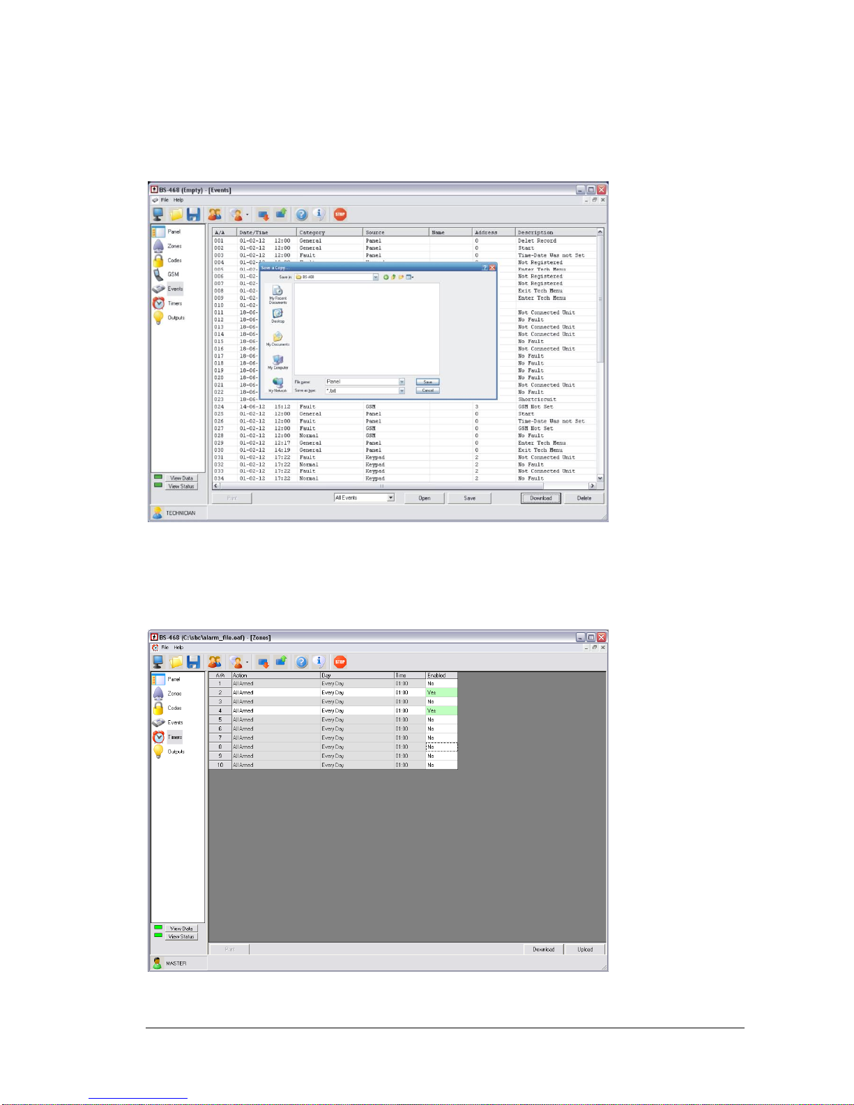
Warning!!
The events of the panel are not stored with the settings of the panel.
If we want to have the events of the panel we can store them in a separate file by clicking the button
«Save» on the lower right side as shown on the screen below.
With the button «Open» we can open a stored events file.
Timer settings
With the timers option we can program automatic arming and disarming of the system.
Page 42
11-4-2017 42 921468001_09_015
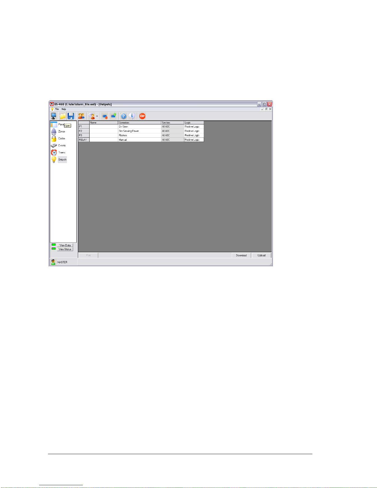
The screen above shows timer 2 used to disarm section A every Wednesday at 7:00 AM whereas
timer4 arms the system every Wednesday at 7:00 PM.
Output settings
The option OUTPUTS is used to show all the outputs. The function is as described in altering the
outputs by the BS-466 keyboard.
In the name column we can enter a name of the output so we can remember its function i.e.
WATERING. This information is only available in the software file and it is not transferred to the panel.
Page 43
11-4-2017 43 921468001_09_015
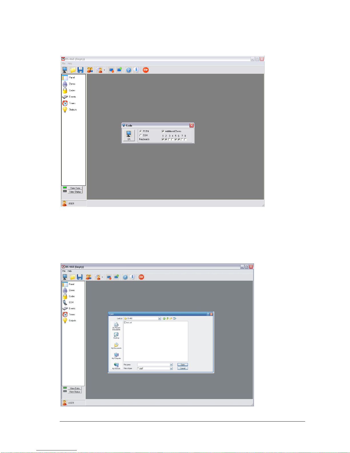
New file
With this option we can start a new installation without the panel being connected.
First we select what the panel will contain e.g. GSM, keyboards 1,2,5 and 6.
Next we alter all the required settings and save the file using the selection File Save.
Open file
When we select to open a file, a window in shown like in the screen below.
Page 44
11-4-2017 44 921468001_09_015
Select the file you want to open, e.g. the test.oaf.
To program the panel with the settings of the file we must first connect the PC with the BS-466
keyboard using the mini-USB cable.
Then we can do a transfer of the settings to the panel as shown in the screen above.
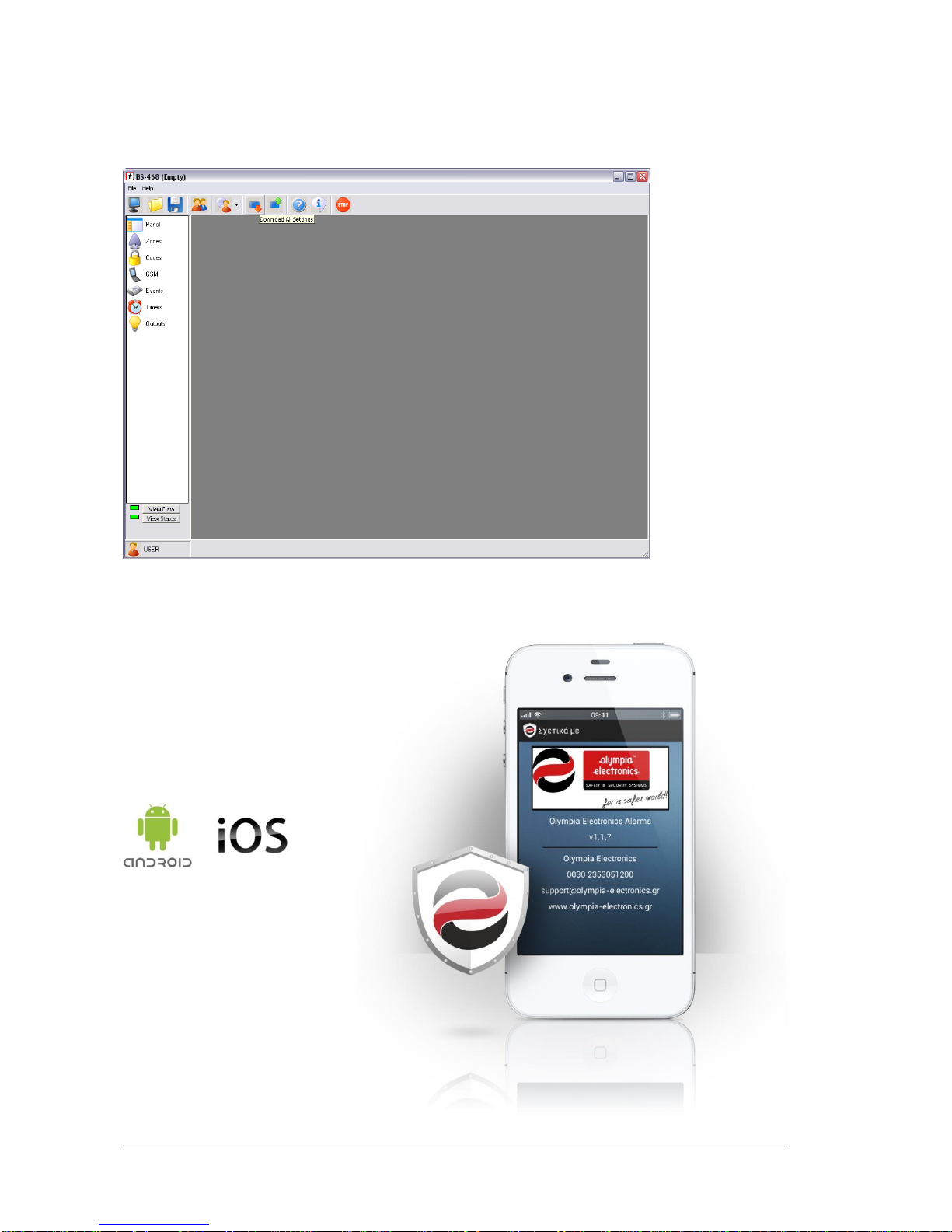
I - OLYMPIA APPLICATION
“Olympia Electronics Alarm” application is available
for smart phones and tablets for Android or IOS.
You can download it at Google play
or Apple store.
Page 45

11-4-2017 45 921468001_09_015
4. Technical Characteristics
Description
BS-468 Burglar alarm system
Power Supply
220-240V AC/50-60Hz
Consumption
25VA
Battery type
Sealed lead acid (Pb) battery 12V / 7Ah Max (not included)
Charger
Stabilized power supply 13,8V / 400mA
AS siren circuit
The AS output powers the external sirens and is used to charge the
battery of the siren with a rating of 13,8V 500mA. This output continuously
provides power.
ES siren circuit
The ES output is used to power the internal siren and provides13,8V up to
500mA. It is activated during an alarm and is deactivated when the alarm
is finished.
Outputs P1,P2,P3
General outputs with a 13,8V 200mA rating. These outputs are activated
depending on the settings of the panel.
Output Relay
A relay output with volt-free contacts ( NC,C,NO). The contact has the
following rating 1A and up to 30VDC.
Output 12V
General power output for devices (13,8V 500mA).
Zones
8 to 24 independent zone inputs. Terminal resistor 5,6kOhm
Maximum load
The maximum load connected to the panel(Outputs P1,P2,P3, BS-466,
12V e.t.c) must not exceed 1Α.
Degrees of cover
protection
IP30
Humidity
Up to 95% relative humidity
Constructional material
ABS - polycarbonate
Dimensions
322 x 241 x 97 mm
Weight
1300 gr
Produced in accordance with
EN 50131-1_Grade 2_Class II and EN 50131-6_Type A
Guarantee
2 years (6 months for A-986 battery)
Page 46
11-4-2017 46 921468001_09_015
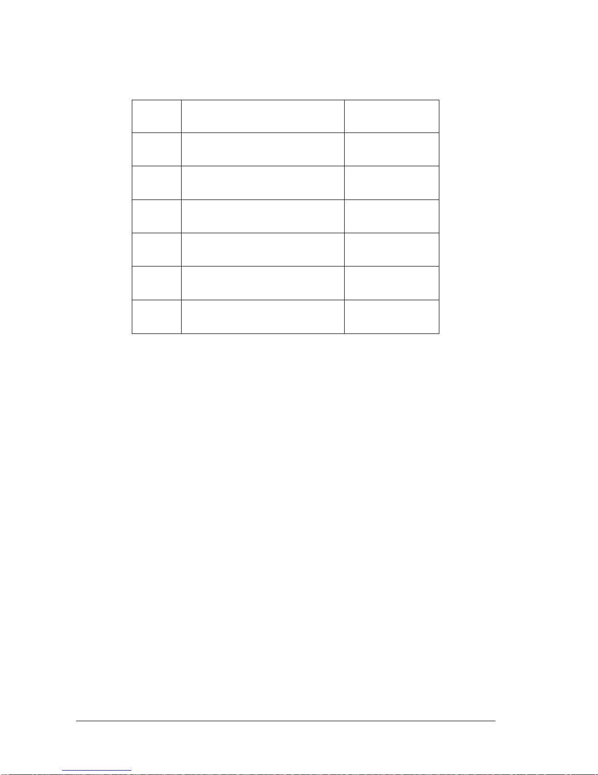
4.1. Peripheral device consumption chart
Type
Description
Consumption in mA
BS-463
Keyboard without display
40mA
BS-464
GSM telephone dialer card
120mA
BS-465
PSTN telephone dialer card
40mA
BS-466
Keyboard with LCD display
45mA
BS-469
8 zone expansion card
40mA
RF-468
Remote control card
10mA
WARRANTY
Olympia Electronics guarantees the quality, condition and operation of the goods. The period of
warranty is specified in the official catalogue of Olympia Electronics and also in the technical leaflet,
which accompanies each product. This warranty ceases to exist if the buyer does not follow the
technical instructions included in official documents given by Olympia Electronics or if the buyer
modifies the goods provided or has any repairs or re-setting done by a third party, unless Olympia
Electronics has fully agreed to them in writing. Products that have been damaged can be returned to
the premises of our company for repair or replacement, as long as the warranty period is valid.
Olympia Electronics reserves the right to repair or to replace the returned goods and to or not charge
the buyer depending on the reason of defection. Olympia Electronics reserves the right to charge or
not the buyer the transportation cost.
HEAD OFFICE
72nd km. O.N.R. Thessaloniki-Katerini
P.C. 60300 P.O. Box 06 Eginio Pierias Greece
www.olympia-electronics.gr
[email protected]
Page 47
11-4-2017 47 921468001_09_015
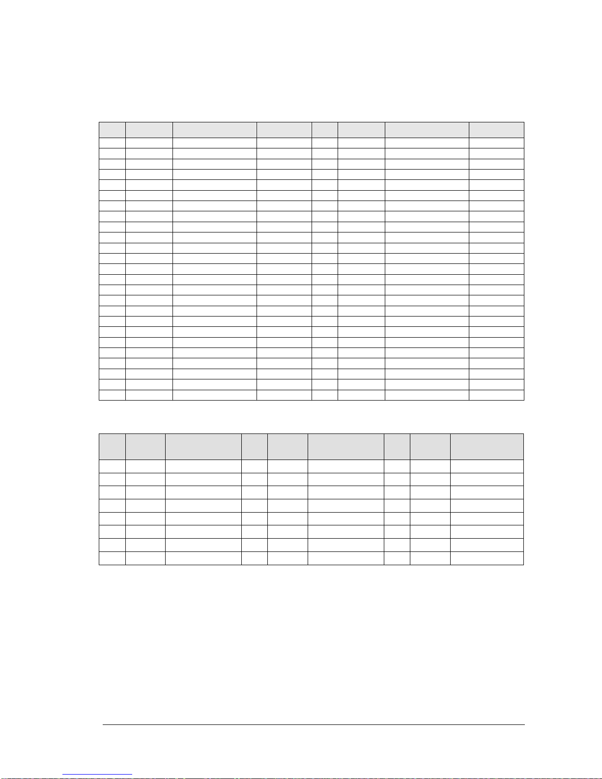
4.2. Information regarding the installation
Passwords
Master password: (1 2 3 4 ) ____________
Α/Α
Password
Owner
Function
Α/Α
Password
Owner
Function
01 26 02 27 03 28 04 29 05 30
06 31
07 32 08 33 09 34 10 35
11 36
12 37 13 38 14 39 15 40 16 41 17 42
18 43
19 44 20 45 21 46 22 47
23 48
24 49 25 50
Zones
Α/Α
Section
(Α Β C)
Area
Α/Α
Section
(Α Β C)
Area
Α/Α
Section
(Α Β C)
Area
01
09
17
02
10
18
03
11
19
04
12
20
05
13
21
06
14
22
07
15
23
08
16
24
Various information
Entry time : ________ seconds Exit time : _________ seconds
Siren time : ________ minutes
Technician password: ( 9 9 9 9 ) ____________
 Loading...