

Page 1

921413000_09_008
Page 1 from 4
13 ,6 -1 4, 8V D C
6m A
Ba yb le nd F R3 01 0, c le ar p ol yc ar bo na te ( re d)
USAGE
BATTERY TYPE
For external use
12V/1 ,3Ah Pb ( seale d lead- acid) ( not inc lu ded )
IP 20
115 d B / 1m
-1 0 60 C
o
έω ς
Up t o 95 %
2 ye ar s (6 m on th s fo r A-989 battery)
17 00 gr.
29 0x 95 x1 90 mm
BS-413
EN 5 01 30 -4 , EN 5 50 22 , EN 6 09 50 -1
TECHNICAL CHARACTERISTICS
RELATIVE HUMIDITY
CONSTRUCTION MATERIAL
WE IG HT
EX TE RN AL DIAMENSIONS
GU AR AN TE E
OPERATION VOLTAGE
QUIESCENT CONSUMPTION
SOUND LEVEL
PRODUCED IN ACCORDANCE WITH
OP ER ATI ON TEMPERATURE RANGE
DE GR EE S OF C OV ER P RO TE CT IO N
Auton omous ele ctronic s iren
with b e acon for b u rglar ala rm panels
GENERAL
tampered with.
The BS-413 alarm siren is of robust design and
If you require, the siren to also be activated if the
can be used with conventional burglar alarm
siren is dismounted from the wall. you must
panels such as the BS-468. It has a red beacon
connect the T1, T2 (TAMPER) inputs.
that blinks when the siren is activated and a
In case of maintenance or if the siren is moved
piezo speaker that produces a sound level of
from it’s mounting position, the SE (Service)
115dB at 1 meter.
input of the siren must be connected to the (-) of
The incorporated tamper mechanism protects
the panel and the panel must be set to OFF.
the siren from unauthorized access when the
cables are cut, the cover is removed or when
Battery
the siren is unmounted from the wall.
If the battery has not been connected then the
siren produces a single tone sound every 1
Mounting
second.
It is mounted externally on a flat surface and at
Whereas if the battery does not operate
a height of about 2,5 meters. Also it should be
correctly, a 3 tone sound is emitted every 12
placed in an area that does not obstruct the
hours.
sound.
Beacon
WARNING!!!
There is a two position (ON, OFF) jumper on the
All 4 mounting screws must be used.
siren which is marked (LED FLASΗ). If a link is
placed on the (ON) position, the beacon blinks
Connection
every 4 seconds in the quiescent state. If no
The connection between the siren and the BS-
jumper is placed then the beacon is OFF during
468 panel is shown on figure 1.
the quiescent state and blinks during the alarm.
After finishing with the connections, connect the
battery cables, install the internal cover and the
Start signal
front fascia of the siren by installing the screws
There is also another 2 position jumper marked
on the bottom side. Finally remove the cable
(TRIGGER) with the positions (-) and (+).
connected to the SE (Service) of the siren from
This jumper sets if the trigger in positive or
the (-) of the panel. The siren will sound once to
negative. Α positive trigger means that the ST
indicate that it is ready to operate and receive a
(START) signal must be a positive voltage for
command from the panel.
the siren to be activated.
The siren now charges the battery and is ready
to accept an ALARM signal from the panel or if
the cables are cut. If we connect the Τ1, Τ2
(TAMPER) signals then it will be activated if it is
Thank you for your trust in our products
Olympia Electronics - European manufacturer
Page 2
Alarm Alarm duration
The siren sounds the alarm in 2 cases, when The siren is activated for as long as an alarm
the ST (START) signal is activated or when it’s signal is issued but stops after 7 minutes. The
power is interrupted. siren will be reactivated with a new alarm signal.
A total of 7 cables are needed for connecting the siren.
2 cables are needed for connecting the siren power supply.
The third cable is used for the ST (START) signal.
The fourth cable is the signal for the beacon FL (FLASH), which in not mandatory for the operation of
the siren.
The fifth cable is for the SE (SERVICE) signal that prevents the siren from sounding during the
installation. It must be connected during the connection procedure and disconnected (from the panel
side) after the installation has finished.
The remaining 2 cables are used for connecting the T1, T2 (TAMPER) inputs of the siren to the Ζ8 zone
TAMPER of the panel. This method permits the siren to sound if tampered with and will also activate the
auto telephone dialer.
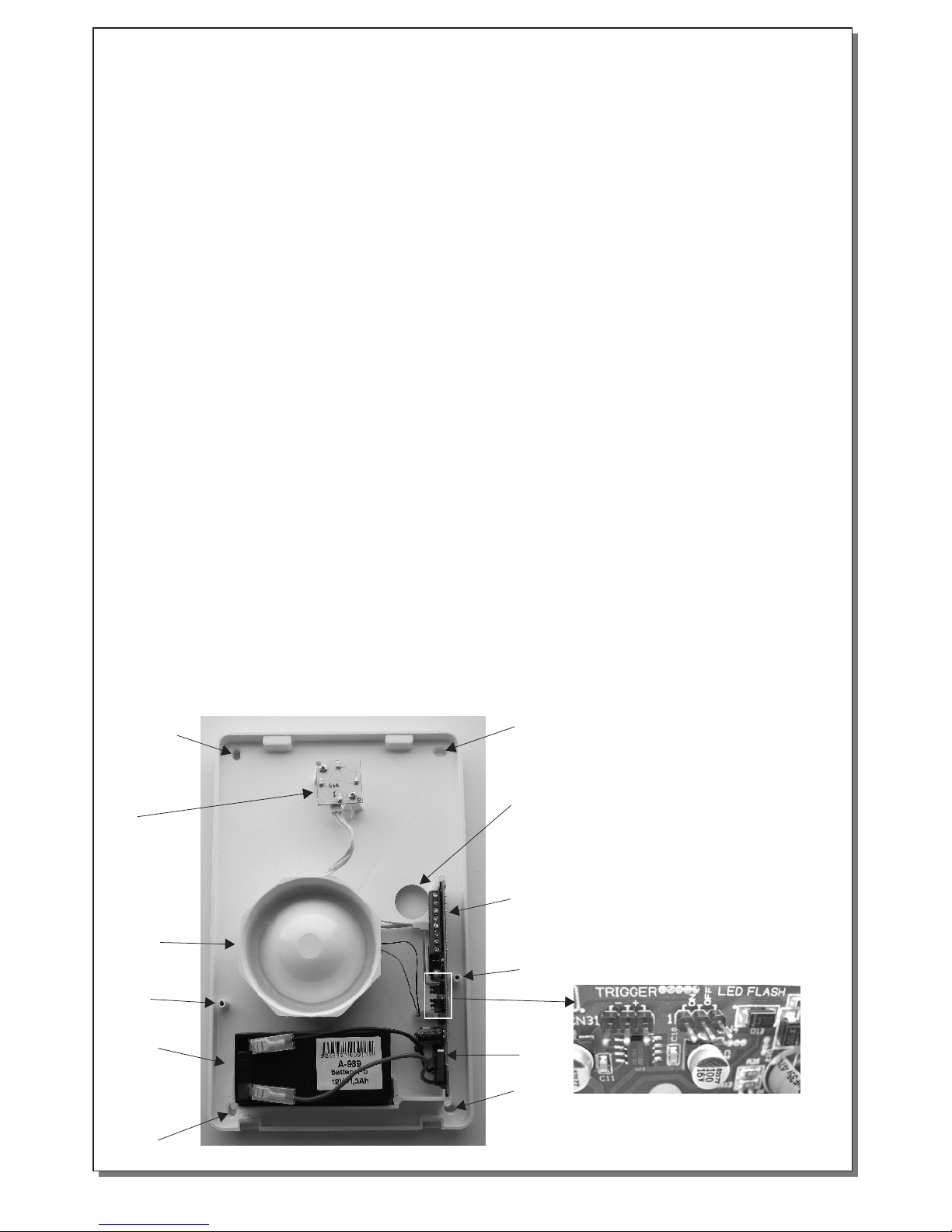
1. Mo untin g poin ts (Al l four s crew s
mus t be use d )
2. In ner cov er mou ntin g poin ts
3. Pi ezo meg apho ne
4. Co nnect ion te rmin als
5. Ba ttery c ompa rtme nt 12V /1,2 Ah
6. TAM PER pr otec tion me chan ism
7. Be acon
8. Ca ble ent ry hol e
Fig ure 2. Th e main p arts o f the si ren
1
1
1
1
2
6
2
7
3
4
5
8
Jum per s
921413000_09_008
Page 2 from 4
Installation Instructions
Page 3
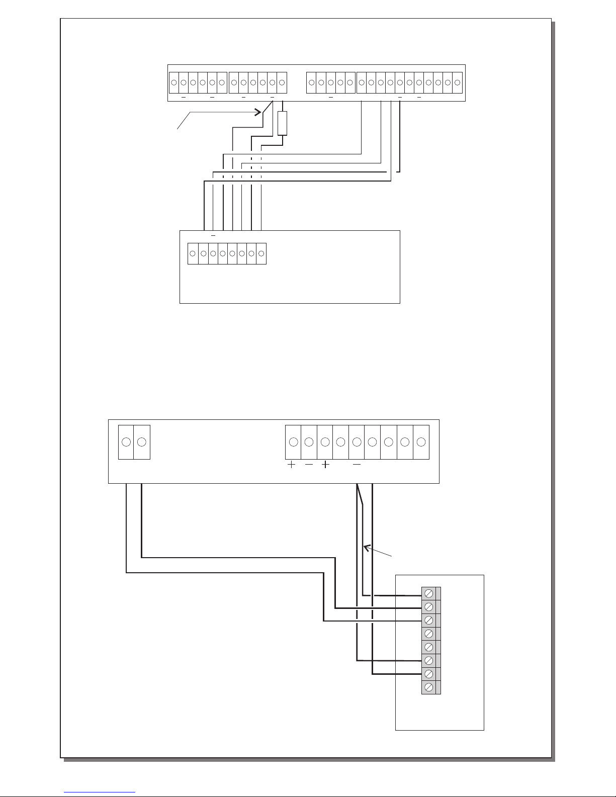
Connections
Z1 Z2 Z3 Z4 Z5 Z6 Z7 Z8
12V12V
A B P1 P2 P3 AS ES NO C NC ANT
5K6
Siren BS-413
Figure 1. Connecting a BS-413 siren to the BS-468 panel
Remove this
cable after the installation
has finished
24_H
C C
12V
ALARM RELAY
SIRENS
NOCNC
TC
EXT AUTO
Remove this
cable after the installation
has finished
Si ren
BS -413
Figure 2. Connecting a BS-413 siren to the BS-418 panel
921413000_09_008
Page 3 from 4
SE
T1
T2
+
+
-
++ ST SE T1 T2FL
Page 4
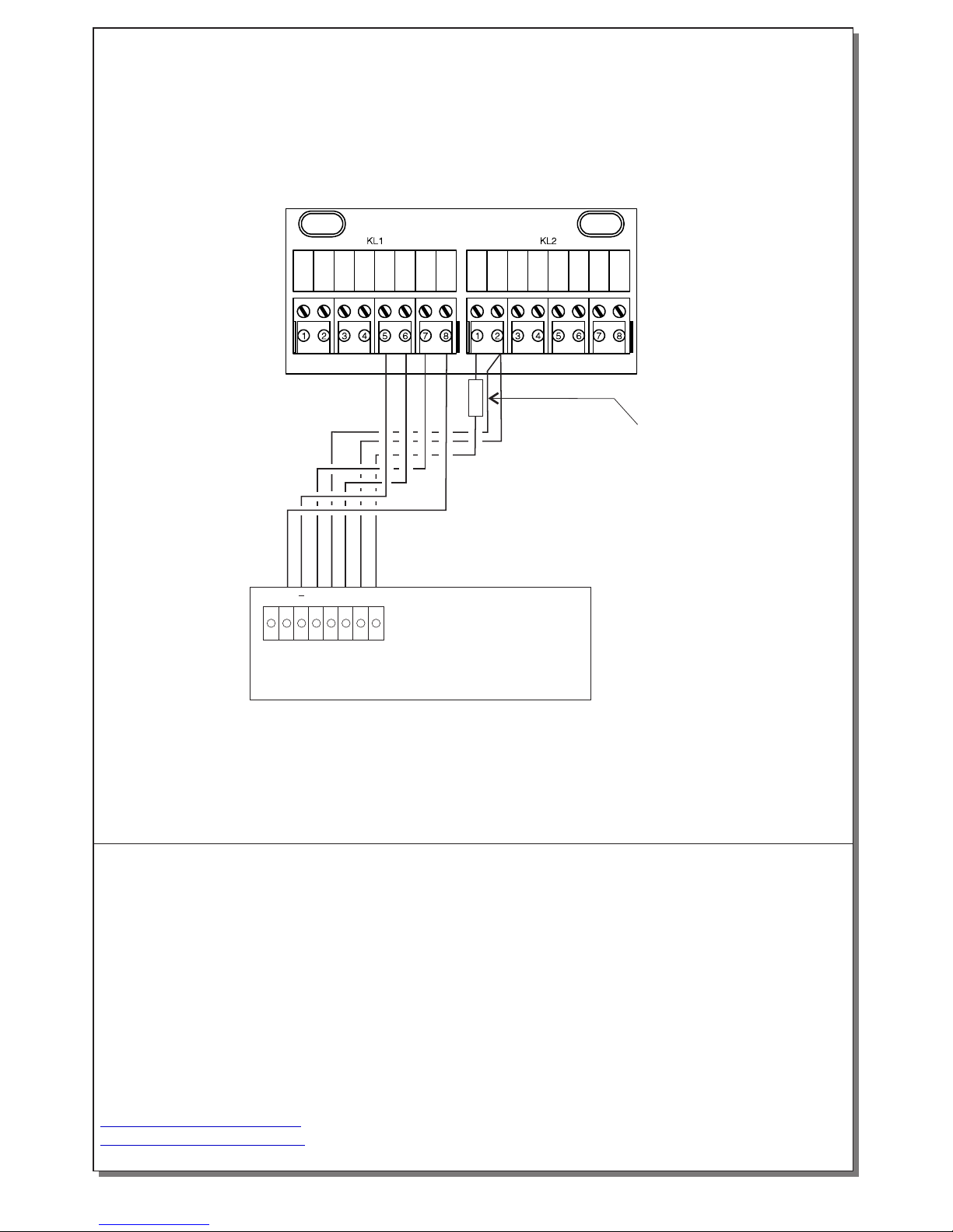
Figure 3. Connecting a BS-413 siren to the BS-458 panel
Remove this
cable after the installation
has finished
BS-458
N
L
P2
P1
Z1
Z2
Z3
Z4
AS
TAMPER
-12V
-
-
-
-
+12V
Siren BS-413
++ ST SE T1 T2FL
5K6
921413000_09_008
Page 4 from 4
WARRANTY
Olympia Electronics guarantees the quality, condition and operation of the goods. The period of
warranty is specified in the official catalogue of Olympia Electronics and also in the technical leaflet,
which accompanies each product. This warranty ceases to exist if the buyer does not follow the
technical instructions included in official documents given by Olympia Electronics or if the buyer
modifies the goods provided or has any repairs or re-setting done by a third party, unless Olympia
Electronics has fully agreed to them in writing. Products that have been damaged can be returned to
the premises of our company for repair or replacement, as long as the warranty period is valid.
Olympia Electronics reserves the right to repair or to replace the returned goods and to or not charge
the buyer depending on the reason of defection. Olympia Electronics reserves the right to charge or
not the buyer the transportation cost.
HEAD OFFICE
72nd km. O.N.R. Thessaloniki-Katerini
P.C. 60061 Greece
www.olympia-electronics.gr
[email protected]
 Loading...