

Page 1
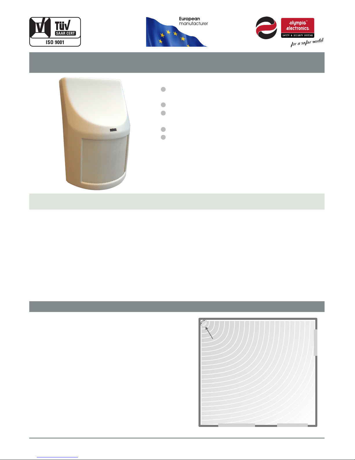
Infrared movement detector for
conventional burglar alarm panels
BS-405/A
BS-405/A
Shielded input stage to protect against
external interference
1, 2 or 3 pulse panel activation selection
Normal or high sensitivity selection to avoid
activating from small pets
Maximum coverage on the vertical axis, 12m.
Elegant design.
Thank you for your trust in our products
Olympia Electronics - European manufacturer
The BS-405/A movement detector incorporates a
special high efficiency, multi-focal and wide angle
lens. Microprocessor controlled improved circuitry
along with a shielded input stage ensure maximum
protection and external interference avoidance
thus avoiding false triggering of the device.
The product can be mounted either flat on a wall, at
an angle or in a corner depending on the area.
The sensitivity selection can be used to avoid false
triggering in the presence of small pets.
1, 2 or 3 pulse activation is used in areas with
electromagnetic interference to avoid false
unwanted alarms.
Page 1 from 4 921405003_09_007
MOUNTING THE DEVICE
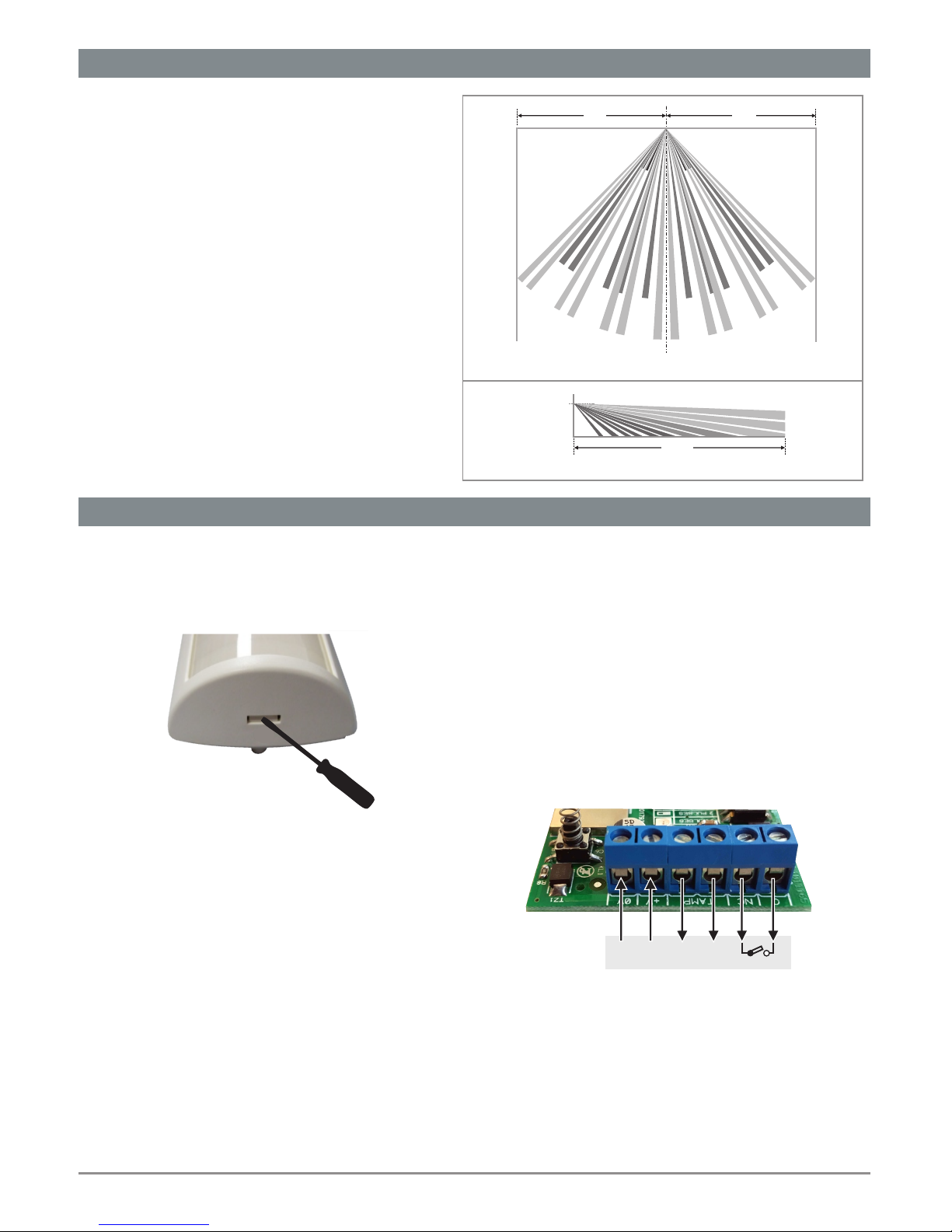
The device must be mounted is such a position in
order to permit the biggest possible surveillance. It
must be mounted at a height between 2,2 and 2,5
meters and ideally at 2,4 meters.
In order to avoid unwanted false alarms, the
detectors must not be mounted in areas that have
hot air or air drafts in general such as over
radiators. It must not be mounted near devices that
emit radio waves such as WiFi repeaters and also
must not be in the path of direct sunlight.
If normal sensitivity is selected then care must be
taken that house pets do not have access to
furniture that is near or at the same height as the
detector in order to avoid false triggering. Physical
obstructions such as walls, furniture, separators,
glass dividers e.t.c must be avoided because they
Room
Door
Balcony Door Window
Mounting example in a typical room
BS-405/A
Page 2
will degrade the detection area of the detector.
The room’s ambient temperature is a great
factor that plays a significant role in the
detection range of the detector. In hot summer
months the detection range is degraded and
can be compensated if we select high sensitivity
during these months.
The product is unsuitable for outdoor use.
MOUNTING THE DEVICE
9m9m
12m
Surveillance zone distribution in the horizontal plane
Surveillance zone distribution in the vertical plane
Page 2 from 4
921405003_09_007
INTERNAL LAYOUT AND SETTINGS
To remove the top cover insert a flat blade screw
driver in the slot . Push the screw driver gently to
unlock the latch and remove the cover.
After removing the top cover it is suggested to
gently remove the circuit board by removing its
retaining screw. Take care not to touch the IR
sensor surface. This will affect is operation.
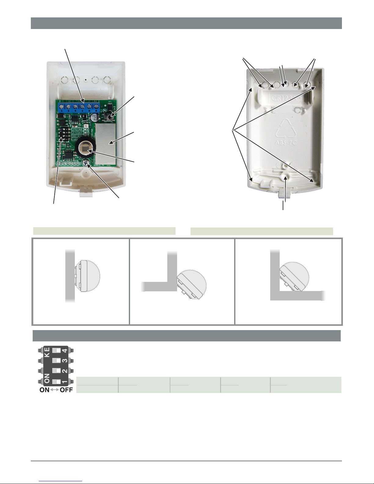
Photograph 1 shows the interior of the plastic
base as well as the cable entry and mounting
hole positions.
To mount the unit to the wall, increase the hole
diameter of points Α to 4 mm. using a suitable
drill bit and mount the unit using the supplied
mounting accessories.
The same can be done if we require to mount
the unit at an angle or in a corner. Drill out
points Β, on the side that will have contact with
the wall and use the supplied mounting
accessories. In corner mounting you can use
one screw on each side to mount the unit.
When mounting has been finished reinstall the circuit
board, if it was removed, and fasten it using the
respective screw. Care should be taken when using
the screw driver in order to avoid any damage.
Finally you can complete the required connections as
shown below: Contacts 1 & 2 are for powering the
device and should be connected to the detector
power supply contacts of the panel. Contacts 3 & 4
are connected to the zone marked 24Η (24hour
zone) and contacts 5 and 6 to any other alarm zone.
-12V+ Tamper
1 2 3 4 5 6
Page 3
INTERNAL LAYOUT AND SETTINGS
Photograph 1
Photograph 2
MICROSWITCH SETTINGS
DS1
Switch 1: Position ΟΝ= The indication LED operates and lights with every detection
Position OFF= The LED in not activatedΗ
Switch 2: Position ΟΝ= High sensitivity detector setting
Position OFF= Normal sensitivity detector settingΗ
Switch 3 OFF ON OFF ON:
Switch 4 OFF OFF ON ON:
1 pulse
2 pulse 3 pulse Not allowed
High sensitivity must be set only in special cases and must be avoided for general use in order to prevent
false triggering of the unit.
“Pulse” defines the full activation of the device. 2 or 3 pulse operation means that the device, after
activation goes to quiescent operation and then is triggered for a second or third time before it sends an
alarm command. It is proposed the 2 pulse operation for typical city environments, with relatively low
electromagnetic noise (factory default). In environments with very low electromagnetic noise the 1 pulse
operation can be selected and in very noisy environments, it is proposed the selection of 3 pulse
operation.
Page 3 from 4
921405003_09_007
Point A, mounting point
for wall mounting
Point Β
Angle or
corner
mounitng
Point C
Cable entry
Point C
Cable entry
Point A
mounting point
for
wall mounting
INTERNAL LAYOUT AND SETTINGS (continued)
Connection
terminals
Settings
Micro-switch
Tamper
switch
Input stage
shield
Infrared sensor
Circuit board
retaining screw
Wall mounting Angle mounting Corner mounting
Page 4
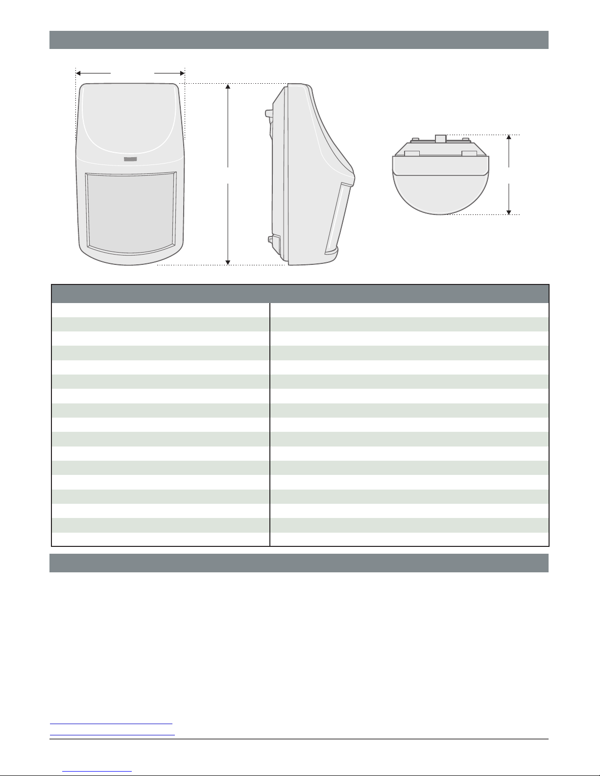
EXTERNAL DIMENSIONS
61,5mm
52,5mm99mm
Page 4 from 4
921405003_09_007
Olympia Electronics guarantees the quality, condition and operation of the goods. The period of warranty is
specified in the official catalogue of Olympia Electronics and also in the technical leaflet, which accompanies
each product. This warranty ceases to exist if the buyer does not follow the technical instructions included in
official documents given by Olympia Electronics or if the buyer modifies the goods provided or has any repairs
or re-setting done by a third party, unless Olympia Electronics has fully agreed to them in writing. Products that
have been damaged can be returned to the premises of our company for repair or replacement, as long as the
warranty period is valid. Olympia Electronics reserves the right to repair or to replace the returned goods and to
or not charge the buyer depending on the reason of defection. Olympia Electronics reserves the right to charge
or not the buyer the transportation cost.
HEAD OFFICE
72nd km. O.N.R. Thessaloniki-Katerini
P.C. 60300 P.O. Box 06 Εginio Pierias Greece
www.olympia-electronics.gr
[email protected]
8 - 16V
12mA
14mA
9 - 12 meters, adjustable
0.25 - 0.3 sec.
30V - 0.2A DC
1 minute (the indication led blinks)
o
-10 to 50 C
Up to 95%
2
ΙΙ
ΙΡ40
ΕΝ50131-1, ΕΝ50131-2-2, ΕΝ50130-4, ΕΝ61000-6-3
Bayblend Fr3010
99 x 61 x 54 mm
70 gr.
2 years
TECHNICAL CHARACTERISTICS
OPERATION VOLTAGE
QUIESCENT CONSUMPTION
ACTIVATION CONSUMPTION
DETECTION RANGE
ACTIVATION TIME
OUTPUT RELAY RATING
INITIAL SETUP TIME
OPERATION TEMPERATURE RANGE
RELATIVE HUMIDITY
DEGREES OF PROTECTION
ENVIRONMENTAL CLASS
DEGREES OF COVER PROTECTION
PRODUCED IN ACCORDANCE WITH
CONSTRUCTIONAL MATERIAL
EXTERNAL DIMENSIONS
TYPICAL WEIGHT
GUARANTEE
WARRANTY
WARRANTY
 Loading...