

Page 1
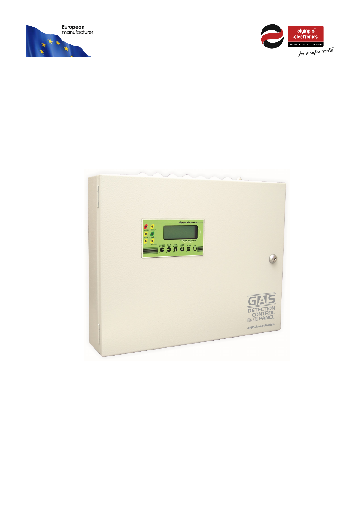
BS-304, BS-308, BS-312, BS-316
Gas detection control panel
up to 16 inputs
Installation – operation manual
Page 1 from 22 921316000_09_016
Page 2

Contents
1 Operation instructions -------------------------------------------------------------------------------------------- 3
1.1 Description ............................................................................................................................ 3
1.2 Indications and Controls ............................................................................................................ 3
1.3 Access level 1 ........................................................................................................................ 4
1.3.1 Events Menu ................................................................................................................... 5
1.4 Access level 2 (User access level) ................................................................................................. 5
2 Installation instructions ------------------------------------------------------------------------------------------- 6
2.1 General description ................................................................................................................. 6
2.2 Security ............................................................................................................................... 6
2.3 Mounting .............................................................................................................................. 6
2.4 Description of the internal parts of the panel ..................................................................................... 7
2.5 Cabling ................................................................................................................................ 7
2.5.1 Connecting the panels with the mains power supply (230V AC) and with the battery ............................... 7
2.5.2 Sensor connectivity ............................................................................................................ 8
2.5.3 Output connectivity ........................................................................................................... 10
2.5.4 Other outputs and their use.................................................................................................. 11
2.6 Network connection ................................................................................................................ 11
3 Technician menu -------------------------------------------------------------------------------------------------- 12
3.1 Access Technician menu .......................................................................................................... 12
3.2 Configuration ........................................................................................................................ 13
3.2.1 Sensor configuration ......................................................................................................... 13
*The parameter increase must be set to NO. ......................................................................................... 14
3.2.2 Relay programming .......................................................................................................... 14
3.2.3 Zones configuration .......................................................................................................... 15
3.3 Information menu .................................................................................................................. 16
3.4 Parameters menu ................................................................................................................... 17
3.5 Enable menu ........................................................................................................................ 19
3.6 Disable menu ........................................................................................................................ 19
3.7 Check menu ......................................................................................................................... 19
3.8 Useful notes to setup the panel BS-316 ......................................................................................... 20
4 Technical Characteristics ---------------------------------------------------------------------------------------- 20
4.1 Record Setup ........................................................................................................................ 22
Page 2 from 22 921316000_09_016
Page 3
General Alarm
General Fault
Disable Point
Power
Test
Fault
Battery
Operation instructions
Thank you for purchasing this product of Olympia Electronics. A European manufacturer.
This section contains general information and information regarding the use of the panel. All users of the panel
should read these instructions very carefully in order to be able to act in the event of an alarm or a fault condition.
1.1 Description
The BS-316 is a gas detection panel with 16 inputs. On each input it can be connected only one gas detector 4-20
mA.
1.2 Indications and Controls
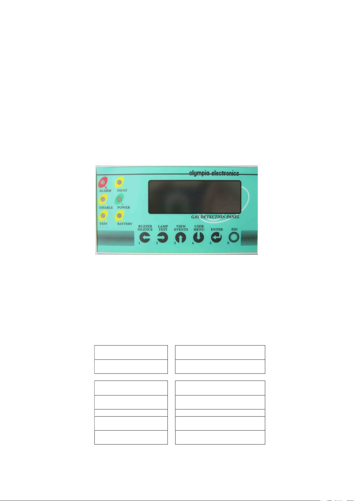
The panel incorporates one liquid crystal display (LCD) and a series of indication LEDs that informs the user about
its status. The indication LEDs give general information (i.e. if an alarm becomes true, then the general alarm
indicator LED will turned ON.) and on display appears information about each event ( i.e. Alarm sensor 1,that
means alarm from sensor 1) .
Figure 1: Main screen of BS-316
Under the display there are 6 buttons for controlling the panel. On each button there is a number 1-6 and
corresponds to the functions left, right, up, down, enter, escape (exit or one step back). Generally by pushing a
button one action happens immediately or one menu appears with some functions. Inside the menu the buttons 1,
2, 3, 4 operate as dimension buttons and we can move inside the menu, the button 5 (enter) to select and button 6
(esc) to come back.
During the next pages we will refer to the buttons using the corresponding numbers.
All LEDs are grouped for easier indication. In detail the LEDs show the following:
(RED)
General alarm indicator Lights in the event of a
(Yellow)
Lights to show a disabled
General operation indicator of
inputs
(Yellow)
Lights to show that we
Lights to show a battery
are in TEST mode
(Yellow)
Fault
(Green)
the panel
(Yellow)
problem
Page 3 from 22 921316000_09_016
Page 4
1.3 Access level 1
This level contains 2 functions that can be implemented by pressing a single key.
- In the event of an Alarm or Fault condition, if the key number (1) is pressed then the internal buzzer is
silenced. For as long as the event is in effect the internal buzzer sounds once in every 30 seconds. Should
the panel see a new event in this state then the buzzer will start to sound continuously.
- When the panel is in standby mode (no alarm or fault events have occurred) then if the key number (2)
(lamp test) is pressed the system conducts a sequential LED and Display test.
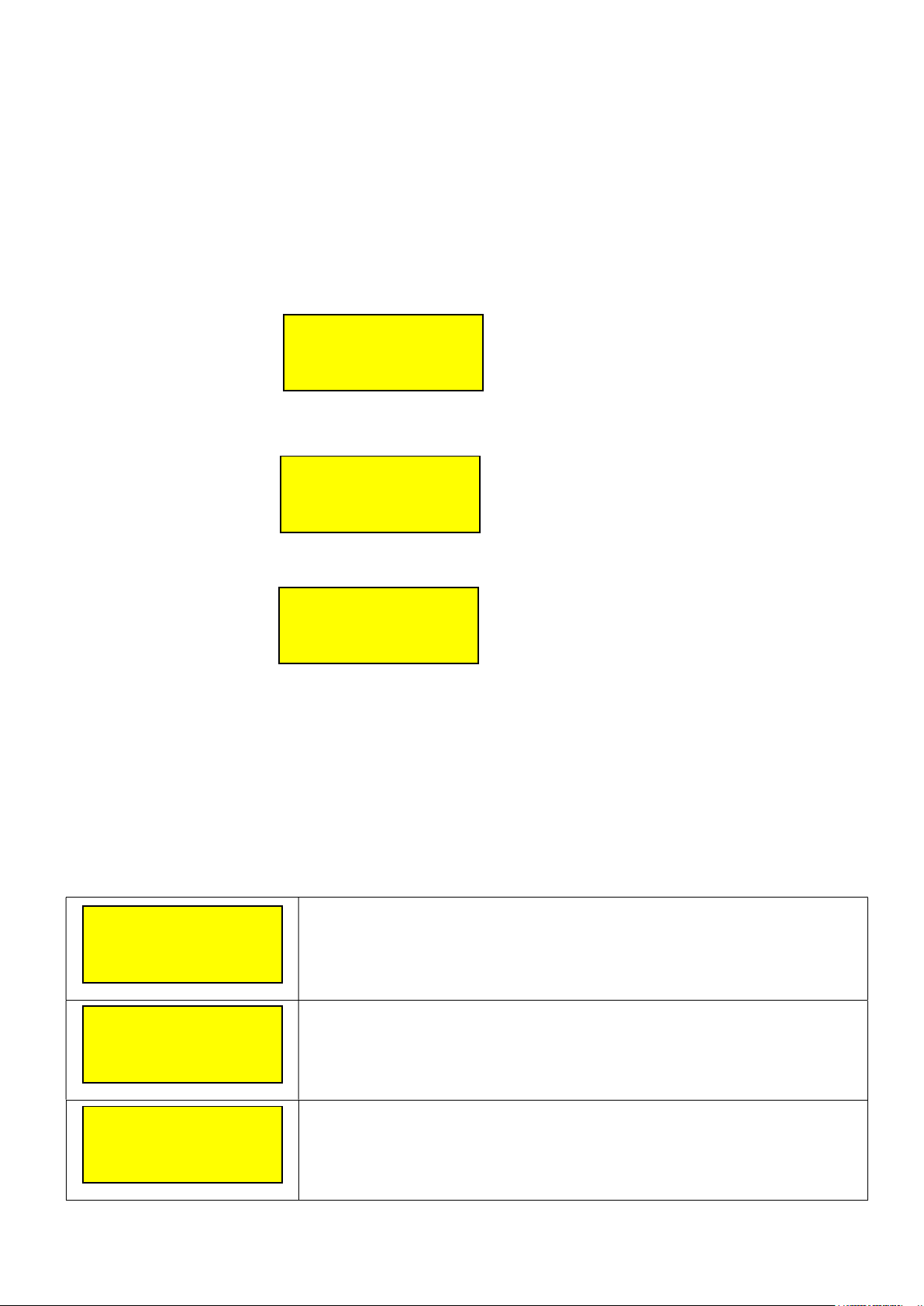
When the system is in quiescence state, the lcd screen shows info about the system.
The below screen shows some information about the system
OLYMPIA ELECTRONICS
BS-316 V.055
12:00:00 20/01/10
SYSTEM READY
The below screen shows the panel name and the technician information.
PANEL NAME
MAIN BUILDING
TECHNICIAN INFO
OLYMPIA ELECTRONICS
The next screen shows the condition of each sensor (input)
1: 0%LIE NORMAL
2: NO CONFIGURATION
3: NO CONFIGURATION
4: 5ppm NORMAL
The sensors 4-20mA incorporates the current have the next situations:
FAULT - (<1 mA)
UNDERFLOW (from 1 to 3.5 mA)
NORMAL (from 3.5 to 21 mA) inside these limits we can do the setup of alarm 1, alarm 2 and
alarm 3)
OVERFLOW (from 21 to 24mA)
FAULT+ (24mA and Higher).
There is the disable situation (ΝΟ CONFIGURATION)
In case alarm or fault the LCD display shows the corresponding message.
EVENTS IN SYSTEM
ALARMS 10
This screen shows a summary of the events in the system.
FAULTS 5
ALARM 10
4: 14%LIE ALARM 2
9: 60ppm ALARM 3
16: 20ppm ALARM 1
FAULT 5
1: FAULT +
3: FAULT BATTERY
The alarm screen show which inputs are in alarm condition.
For example the second line 4: 14% LIE ALARM 2 means that the 4th input
sensor has detected 14% LIE of a gas and it is at ALARM 2 state.
The screen on the left shows the faults of the system.
For example the second line 1: FAULT + means that the 1st input sensor has a
FAULT +.
Page 4 from 22 921316000_09_016
Page 5
1.3.1 Events Menu
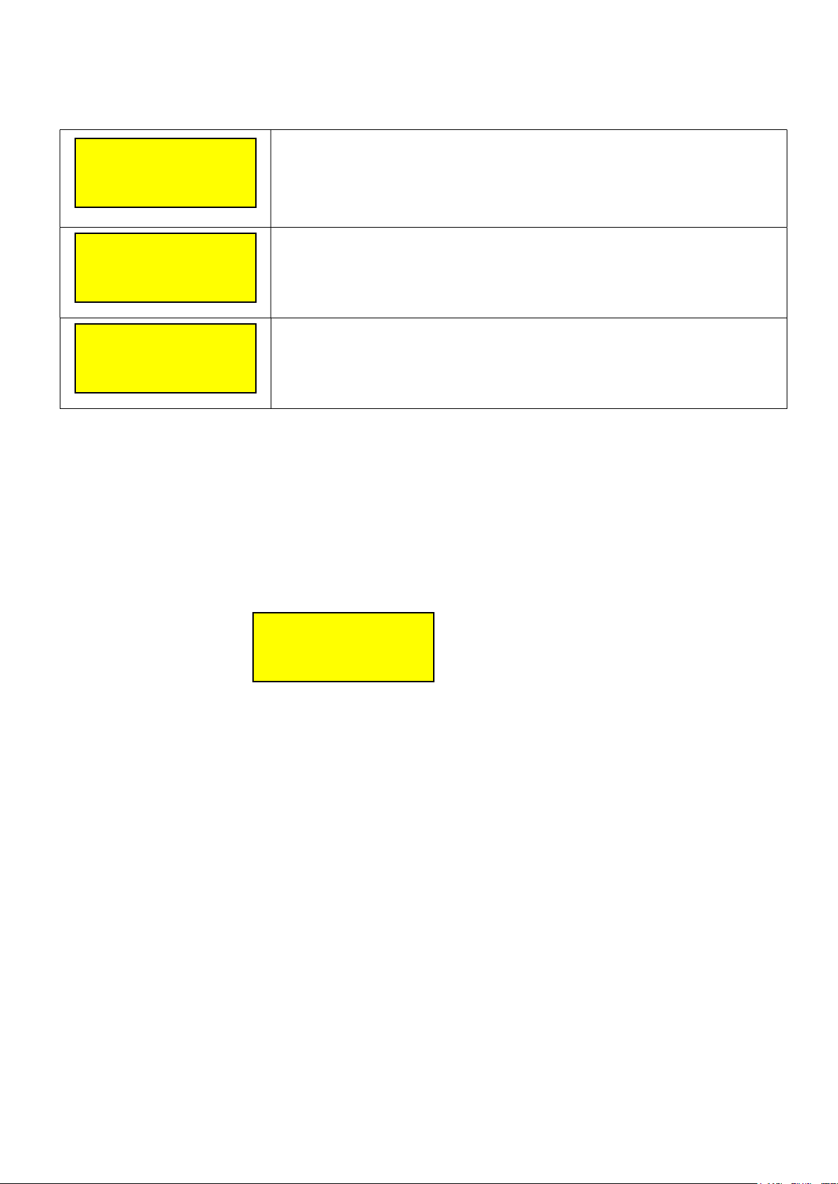
All the events of the system can be shown by pressing the key “3” View Events and then the key Enter.
ALARM 1 ( 59/ 59)
15%LIE S= 4 Z= 2
11:03:45 20/01/10
CAR PARKING - LPG
FAULT ( 13/ 59)
BATTERY
11:00:05 18/01/10
This screen on the left shows that the system has recorded 59 events. The
event shown in the example shows that this event is a ALARM 2 of the 4th
sensor (S=4) which belong to zone 2 (Z=2).
The third line in the timestamp when the event occurred.
The last line is the name of the sensor.
This screen on the left shows that the battery was disconnected at 11:00 on
18/01/10.
BATTERY DISCONNECTED
GENERAL ( 5/ 59)
PANEL
The screen on the left shows the panel start operating from 09:00 on 10/01/10.
09:07:00 10/01/10
START
1.4 Access level 2 (User access level)
All the functions of access level 2 can be accessed from a menu that is displayed when we push the button “4"
User menu.
To Reset the panel, from the central menu, we press button “5” and button “ENTER” and the next message is
displayed.
====================
TYPE USER CODE
---====================
The user code is 1-1-1-1. So the key “1” must be pressed four times.
After this the panel resets.
Page 5 from 22 921316000_09_016
Page 6

Installation instructions
In this section there is information about the connectivity of panel, its peripherals, the programming of all the
functions and troubleshooting. All installers who want to connect and enable the gas detection panel must read this
manual carefully. The whole knowledge of the panel and its peripherals is necessary for work and installation.
General description
Input peripheral analysis for panel BS-316 :
- BS-380. LPG detector waterproof IP65.
- BS-381. Methane gas detector waterproof IP65.
- BS-382. Carbon monoxide detector waterproof IP65.
- BS-383. Ammonia detector waterproof IP65.
- BS-390. LPG detector anti-explosive type.
- BS-391. Methane gas detector anti-explosive type.
- BS-393. Ammonia detector anti-explosive type.
On the AUX input we can connect fire detection buttons, like the BS-536, BS-7000 (IP-65).
We can program and work the panel by using only the buttons that are on its keyboard.
Security
The panel cannot be installed correctly if the installation guide is not read.
This product must be installed, operated and maintained by skilled technician:
Using all rules of electrical product installation in buildings.
Installation guide.
- The operation voltage is 220-240V AC / 50-60Hz.
- Must be connected to the electrical panel of the building, but with a separate fuse.
Mounting
The mounting of panel must be in a visible place with easy access by the users. The panel BS-316 is a product for
easy wall mounting and indoor use. The mounting on the wall can be done by using plugs and screws that are
included in the panel package.
Page 6 from 22 921316000_09_016
Page 7
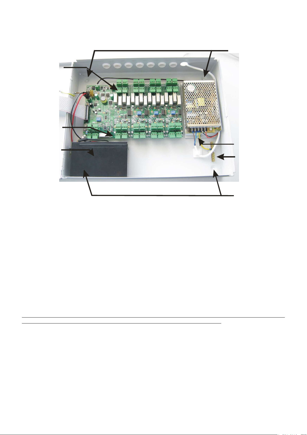
Connect power cable
Description of the internal parts of the panel
Relay terminals
Inputs terminals
Place batteries
Mounting holes
Ground terminals
Mounting holes
Figure 2: Inside the panel
Cabling
The panel has pre-opened passages from where the installation cables will enter the panel.
The terminal blocks of the panel are capable of handling cable with a cross-section of up-to 2.5mm.
Connecting the panels with the mains power supply (230V AC) and with the battery
To connect the cable with the mains power supply, a cable with double insulation must be used. The connection is done
using the special terminals found on the right side of the panel as shown in the.
The battery can be placed on the bottom side of the panel.
The battery Α-986 of olympia electronics can be used. The charging circuit of the panel is also calculated for the
specific battery type. In case of replacement, the new battery must be of the same type.
Two cables with connectors are used to connect the battery to the panel. The black cable is connected to the
negative pole of the battery (marked with (-) or with black color) and the red cable is connected to the positive pole
of the battery (marked (+) or with red color).
Warnings.
1. During the installation, the connections to the mains power supply and the battery must be done after all
other connections are finished.
2. The panel connection with the mains supply must be done via a 16A external fuse or an automatic circuit
breaker rated at 16A.
3. Always use cables with double insulation.
4. The diameter of the cable must be at least 1mm.
5. The inner insulation of each cable must not be cut more than 1cm
6. The outer insulation must not be cut more than 1cm away from the internal insulation.
Page 7 from 22 921316000_09_016
Page 8
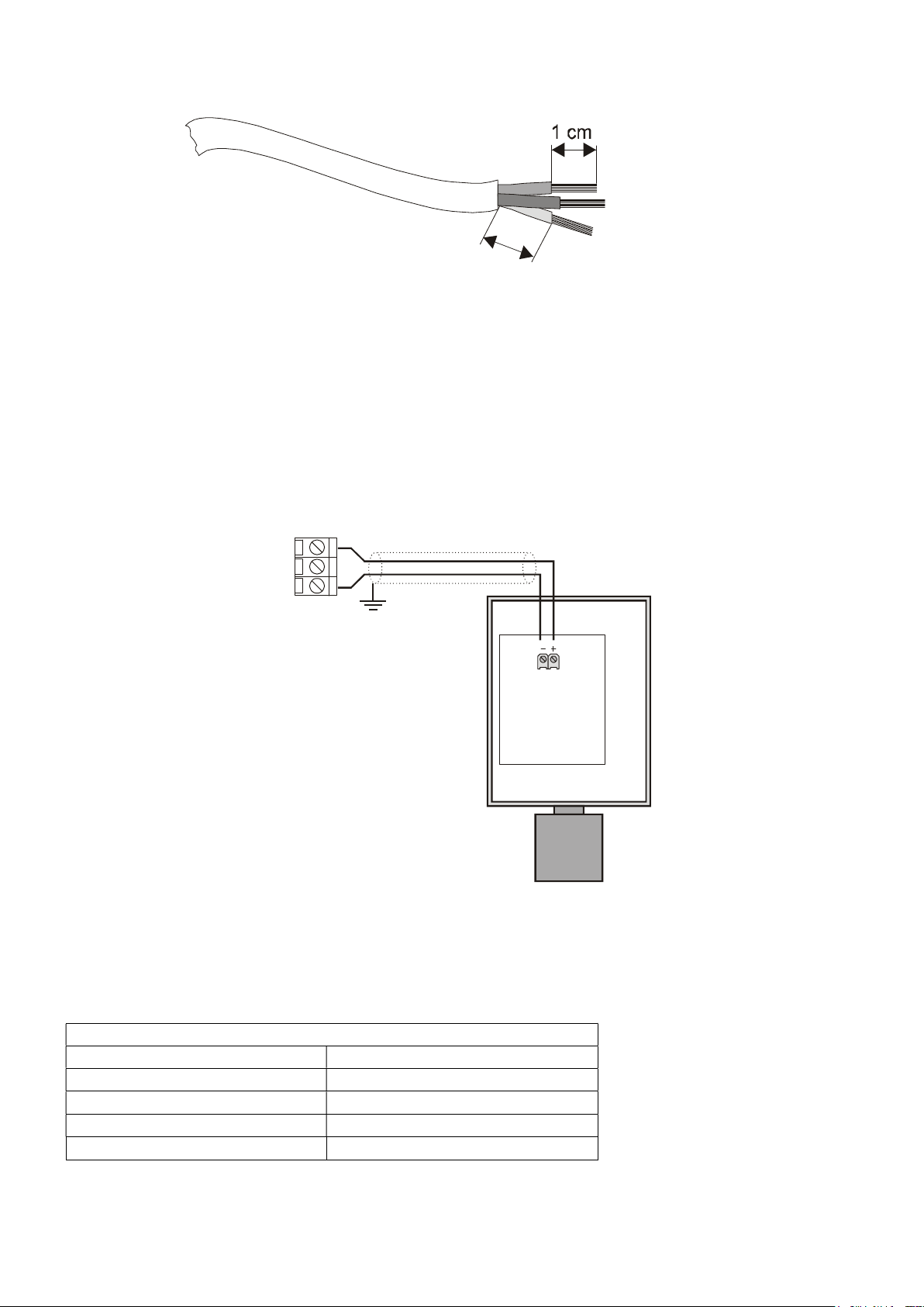
Sensors
with
two contacts
Ranges
Cable type
Power
Figure 3:
cable
Sensor connectivity
Before connecting any sensor to the panel, the main power supply must be disconnected. There are two ways of
connect the sensors depending on the number of contacts.
Α) Sensor with 2 contacts 4÷20mA
The connection of sensors with 2 contacts 4÷20mA must be between «+» and «-» of the sensor connector, that
correspond to «+» and “S” of the panel as shown in figure 4.
+
-
S
Figure 4: Connection diagram with two contact sensors
The cross-section of the cable depends on the length (see next table). On all sensors with 2 contacts you must
connect a coaxial cable. The shielding of the cable must be connected to the «-» of sensor.
From 0 to 100 meters 2 x 0,5 mm² shielded
From 100 to 200 meters 2 x 1 mm² shielded
Frοm 200 to 500 meters 2 x 1,5 mm² shielded
Frοm 500 to 1000 meters 2 x 2,5 mm² shielded
Β) Sensors with 3 contacts 4÷20mA
Page 8 from 22 921316000_09_016
Page 9
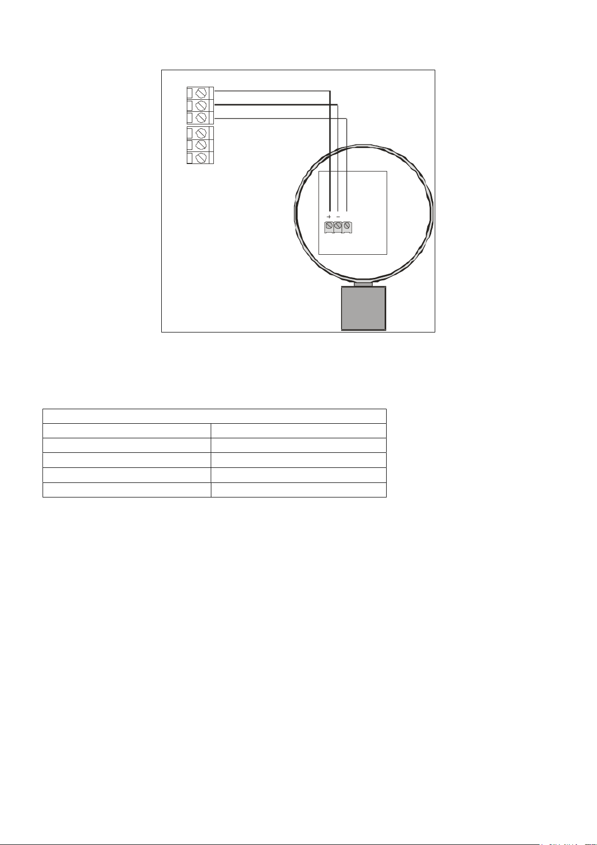
Ranges
Cable type
The connection of sensors with 3 contacts 4÷20mA, must be between «+», «-» and “S” of sensor that correspond
to «+», «-» and “S” of panel as shown in figure 5.
+
-
S
+
-
S
S
BS-390
Figure 5: Connection diagram with three pad sensor
The cross-section of the cable depends on the cable length (see next table). The sensors with 3 contacts do not
require coaxial cables.
Sensor series with three contacts
From 0 to 300 meters 3 x 0,75 mm²
Up to 400 meters 3 x 1 mm²
Up to 500 meters 3 x 1.5 mm²
Up to 600 meters 3 x 2.5 mm²
The gas sensors, need a preheat time, in clear air, for about 20 seconds. After this time the sensor can sense
gases, but the maximum sense ability is after 3 hours of continuous operation. So a sample gas test should be
done after 3 hours.
The sensors BS-382, BS-383 have maximum sense ability, in clear air, after about 1-2 hours of continuous
operation.
After the electrical connection of the sensors, the technician must power the panel and setup all sensors.
About sensor setup see paragraph 2.6.1.
Page 9 from 22 921316000_09_016
Page 10
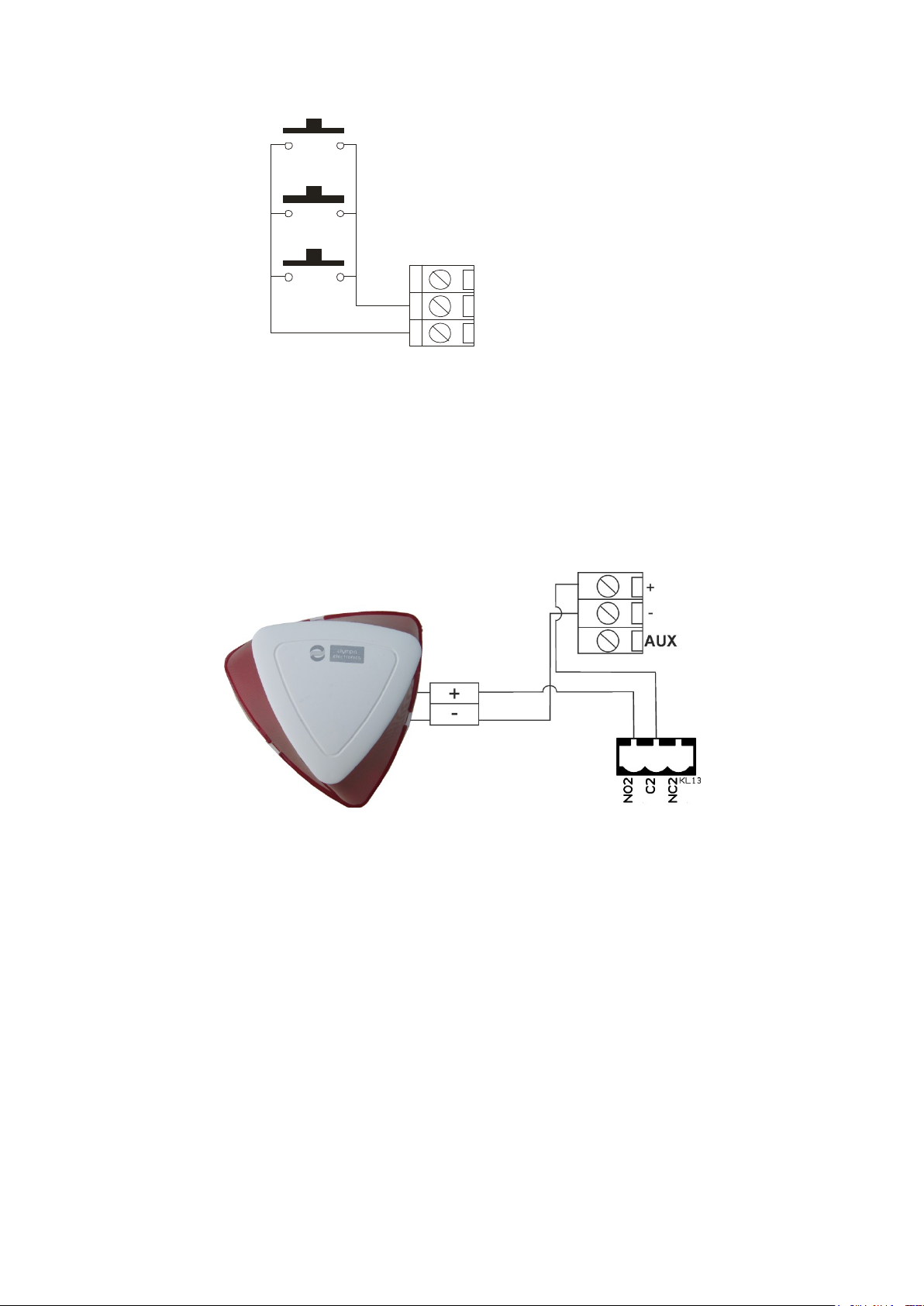
Finally on the AUX input we can connect fire detection buttons between inputs «-» and “S” of (Figure 6).
+
AUX
Figure 6: Connection device diagram on helpful input.
Figure 7: Connection diagram for BS-531.
Output connectivity
On the panel there are 16 programmable outputs relay. Each relay has a triple connector NO, NC, C. For more
information about output setup see paragraph 2.7.1.
Page 10 from 22 921316000_09_016
Page 11
Other outputs and their use
The panel has the following outputs:
- Output AUX. This is an auxiliary power output (between «-» and «+») that has the capability of providing
20Vdc for maximum load of 300mΑ.
- Connectors F_OUT. Open collector output. If there is a general fault (Fault) it is enabled (0V).
NOTE The maximum drawn from output “AUX” must not be more than 300mA.
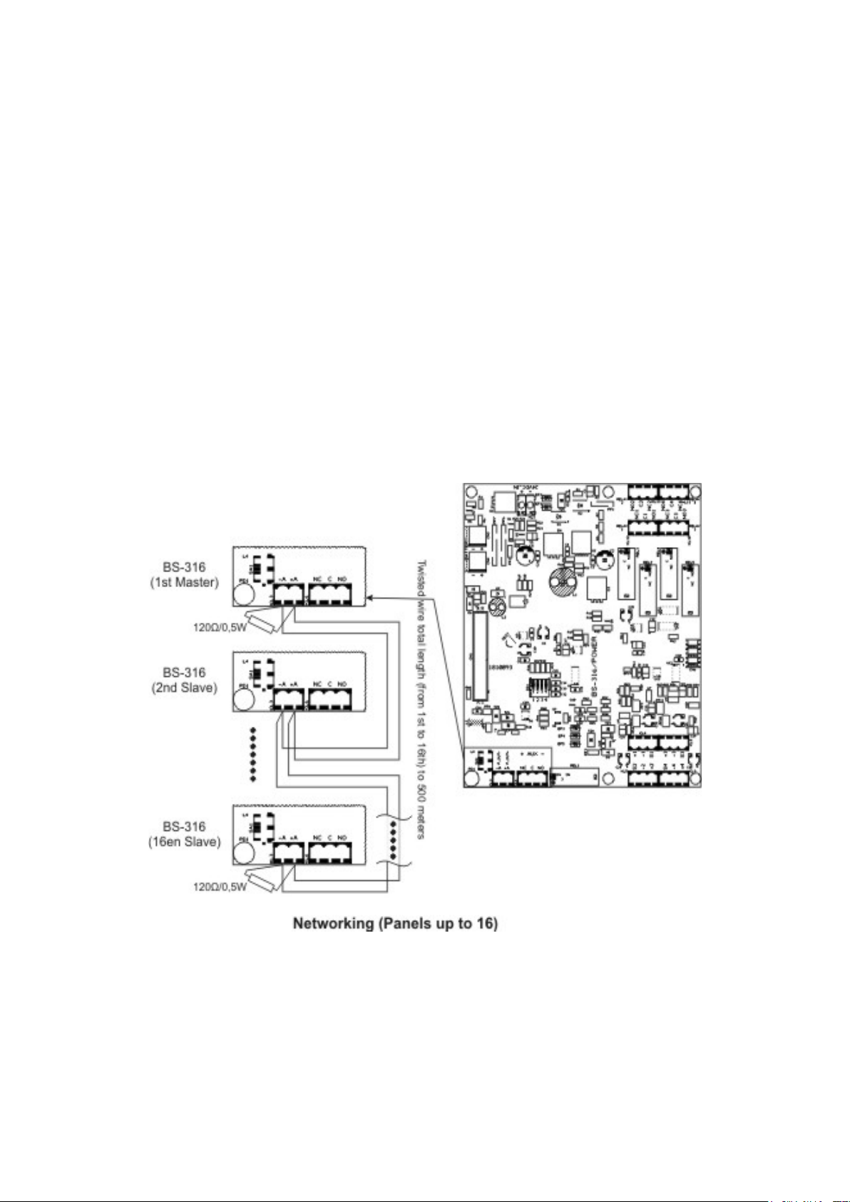
Network connection
It is possible to have network of panels. In each network, each panel has a unique address.
The central panel has address 1 and sub-panels have address from 2 to 16. The figure below shows the network
connection.
The interface cable is two cable twisted. The connection topology is parallel, for example should the cable from one
table to go to another and there are no interconnections
Caution resistors 120Ohm / 0,5 W should be placed at the beginning and end of the cable.
Figure 8: Netowrk connections
Page 11 from 22 921316000_09_016
Page 12
Technician menu
Access Technician menu
All the functions of access level 3 can be accessed from the menu that displayed when we press button “5" in the
technician menu.
The panel prompts for the technician code
====================
TYPE TECHNICIAN CODE
---====================
The technician code is 2-3-3-3.
After the code in entered, the operator has access to level 3 functions.
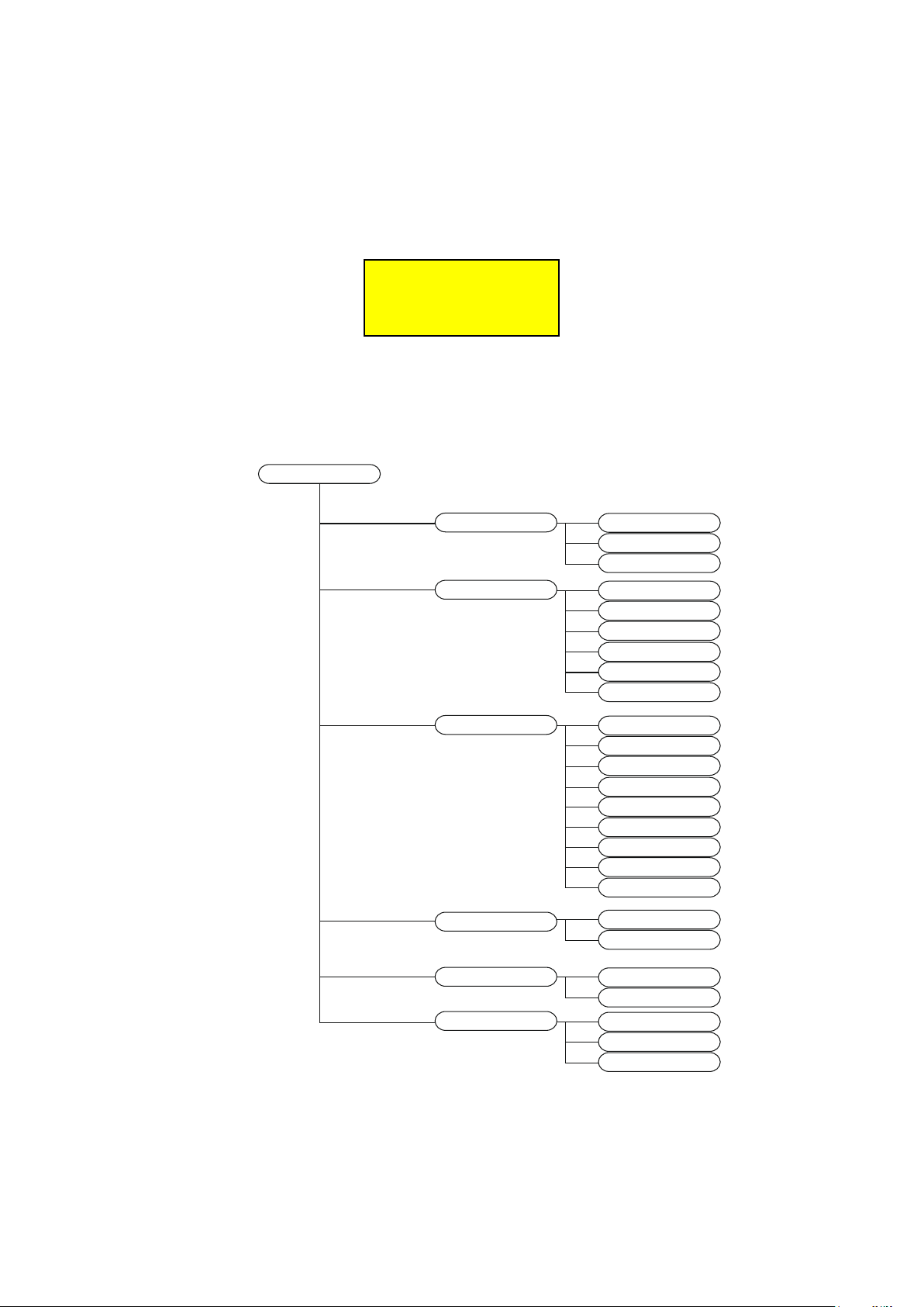
TECHNICIAN MENU
CONFIGURATION
INFORMATION
PARAMETERS
ENABLEMENT
SENSORS
RELAY
ZONES
SENSOR
RELAY
ZONES
BATTERY
MAINS SUPPLY
VCC VOLTAGE
SCREEN BACKLIGHT
BUZZER AT FAULT
FACTORY DEFAULTS
CHANGE LANGUAGE
HOUR ADJUST
DATE ADJUST
DELETE RECORD
PANEL NAME
TECHNICIANS INFO
ENABLE ALL SENSORS
ENABLE A SENSOR
Page 12 from 22 921316000_09_016
DISABLEMENT
CHECK
Figure 9: Technician Menu
DISABLE ALL SENSORS
DISABLE A SENSOR
SENSORS
RELAY
ZONES
Page 13
SELECT ENTER
SELECT ENTER
SELECT ENTER
Figure
10: Menu to setup a sensor
Configuration
In the configuration menu the technician can configure the sensors, the relays and the zones.
Sensor configuration
The available options in the configuration sensor menu, are shown below,
===== SENSORS =====
SETUP SENSOR
====================
===== SENSORS =====
COPY SENSOR
====================
with Setup you can setup a sensor from scratch, with Copy you can copy the setup from one sensor to
another and with Delete you can delete the setup of a sensor.
If you choose the setup a sensor the next screen is shown:
===== SENSORS =====
SELECT SENSOR
[1..16]: 1
====================
where you can choose which sensor you want to setup.
SETUP SENSOR
===== SENSORS =====
DELETE SENSOR
====================
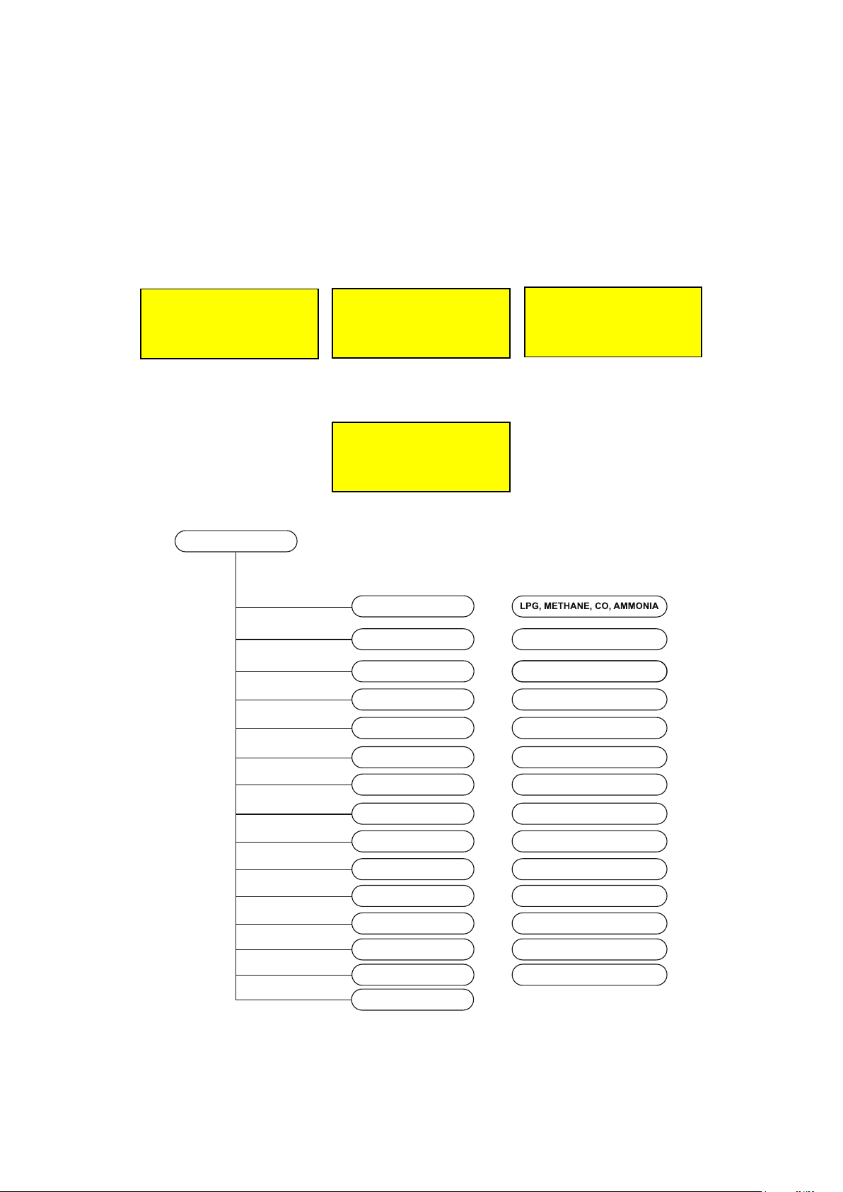
LOAD SETUP SENSOR
NAME
UNIT
INCREASING
ZERO
RANGE
ALARM1
ALARM2
ALARM3
RELAY ALARM1
RELAY ALARM2
RELAY ALARM3
RELAY FAULT
ZONE
SAVE SENSOR?
Maximun 20 characters
ppm, %LEL, %
YES, NO
0...300
0...300
0...300
0...300
0...300
0...17
0...17
0...17
0...17
0...16
The above picture shows the menu to setup a sensor. With the help of the first selection “LOAD SETUP
SENSOR” the defaults values are loaded to the variables of the sensor.
Page 13 from 22 921316000_09_016
Page 14

Type
Gas Zero Limit
Unit Alarm
1
Alarm
2
Alarm
3
SELECT ENTER
SELECT ENTER
SELECT ENTER
The variables above are:
NAME: the name of the sensor. You can put up to 20 characters.
UNIT: Units to meter the gas. There are two kinds of units in ppm or %LIE or %.
INCREASING: if the value is increasing or decreasing.
ZERO: Minimum (start up of scale). Default is 0.
RANGE: Maximum (maximum value of scale). The value range is from 20 to 300.
ALARM 1: Alarm 1 level.
ALARM 2: Alarm 2 level.
ALARM 3: Alarm 3level.
RELAY ALARM 1: the relay that will be activated when there is an Alarm 1 level at the sensor.
RELAY ALARM 2: the relay that will be activated when there is an Alarm 2 level at the sensor.
RELAY ALARM 3: the relay that will be activated when there is an Alarm 3 level at the sensor.
RELAY FAULT: the relay that will be activated when there is a fault at the sensor.
ZONE: the zone of the sensor.
At next table we can see some typical values.
BS-380 LPG 0 20 %LIE 7 10 20
BS-381 Methane
0 20 %LIE 6 10 20
gas
BS-382 Carbon
0 300 ppm 25:50 100 200
Monoxide
BS-383 Ammonia 0 300 ppm 10 20 50:100
BS-390 LPG 0 20 %LIE 7 10 20
BS-391 Methane
0 20 %LIE 6 10 20
gas
BS-393 Ammonia 0 300 ppm 10 20 50:100
- Oxygen* 0 25 % 18 19 22
TC-100N/LPG LPG 0 100 %LIE 8 12 20
TC-100N/CNG Methane
0 100 %lie 8 12 20
gas
*The parameter increase must be set to NO.
Relay programming
All the relays of panel are programmable for connecting any application. The relay programming options in the
configuration of relay menu are shown below,
===== RELAY ======
SETUP RELAY
====================
==== RELAY =======
COPY RELAY
====================
====== RELAY ======
INITIALISE RELAY
====================
with Setup you can setup the relay from scratch, with Copy you can copy the setup from one relay to
another, and with Initialise you can load the default values.
Page 14 from 22 921316000_09_016
Page 15
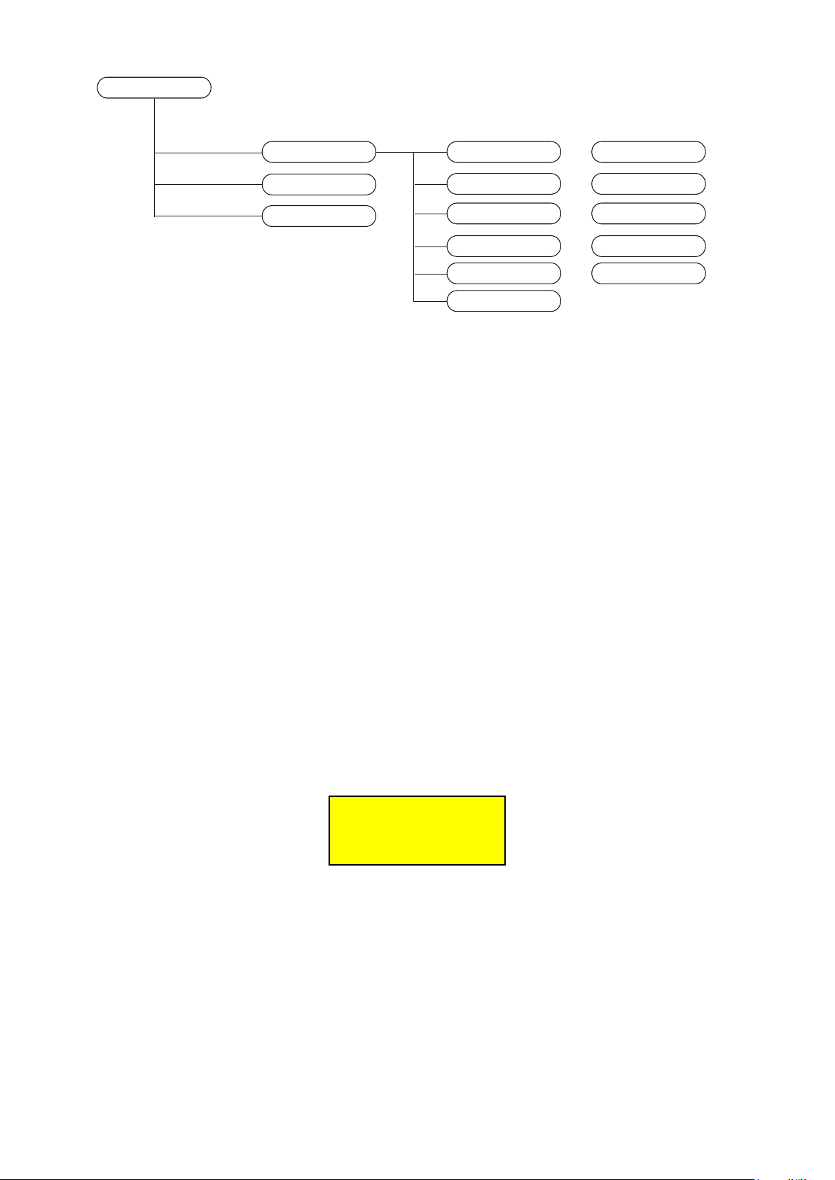
SETUP RELAY
SETUP RELAY DELAY ON
COPY RELAY
INITIALIZE RELAY
DELAY OFF
TIME ON
LOGIC CONTACT
LATCHED OUTPUT
SAVE RELAY?
0..250
0..250
0..250
POSITIVE NEGATIVE
NO YES
Figure 7: Diagram menu setup relay
The above diagram shows the menu for the configuration of a relay:
The parameters are:
DELAY ON : it is the delay time (max 250 seconds) of the output activation from the moment when the gas
concentration is in the alarm setting.
DELAY OFF : it is the delay time (max 250 seconds) of the output deactivation from the moment when the
gas concentration returns under the alarm setting.
TIME ON : it is the maximum time (max 250 seconds) of the output activation when the sensor is in an
alarm condition. After this time the relay is deactivated.
LOGIC CONTACT: it indicates if the relay works normally activated (Positive Logic) (NC) or normally
deactivated (Negative Logic) (NO).
LATCHED OUTPUT: it indicates if you want to keep the output active even if the gas concentration returns
under the alarm setting.
Zones configuration
Zones configuration is a useful procedure to unify the procedures when a sensor is activated. When some
sensors belong to the same zone they activate the same relays, as the zone configuration indicates.
This menu is used for the configuration of the zone. First you must choose which zone you want to change
===== ZONES =====
SELECT ZONES
[1..16]: 1
====================
Below is the zone menu
Page 15 from 22 921316000_09_016
Page 16
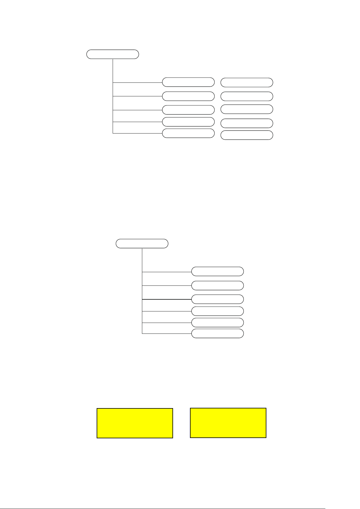
SETUP ZONE
RELAY ON ALARM1
RELAY ON ALARM2
RELAY ON ALARM3
RELAY ON FAULT
SAVE ZONE
1..17
1..17
1..17
1..17
1..17
Figure 12: Diagram menu of the zone configuration
Information menu
From this selection the technician can be informed for all the system. The below diagram shows the menu
INFORMATION
SENSORS
RELAY
ZONES
BATTERY
MAINS SUPPLY
VCC VOLTAGE
Figure 8: Information menu
An example of the information of a sensor screen are
4: FAULT I = 2.0 mA
LPG FLOOR 1
====================
The above left screen shows the number of the sensor, the condition (FAULT -), the current consumption
and the name of the sensor.
4:Z=0 R=20 (+)
A1= 7 A2= 10 A3= 20
O1= 1 O2= 2 O3 = 3
OF= 4 ZONE = 0
Page 16 from 22 921316000_09_016
Page 17
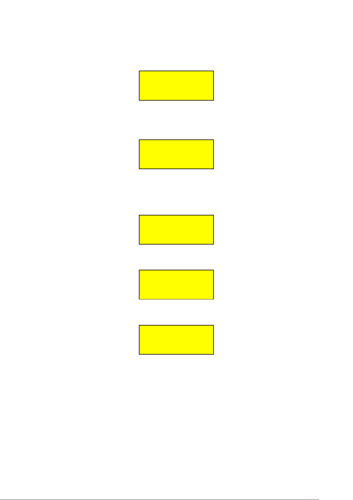
The right screen shows the ZERO, RANGE, ALARM1, ALARM2,ALARM3, RELAY ON ALARM1, RELAY
ON ALARM2, RELAY ON ALARM3, RELAY ON FAULT and ZONE respectively.
To change the sensor, use the button “3” or “4”.
An example of the information relay screen is
==== RELAY 2 =======
D0= 10 DF= 40 TO=20
LOGIC = NO
====================
the above screen shows the delay on, delay off, time on and positive logic respectively
To change the relay, use the button “3” or “4”.
An example of the information zone screen is
==== ZONES 8 =======
O1= 10 O2= 4 O3= 2
OF= 0
====================
the above screen shows the relay on alarm 1, relay on alarm 2, relay on alarm 3 and relay on fault
respectively
To change the relay, use the button “3” or “4”.
An example of the battery information
=== INFORMATION ===
VOLTAGE OF BATTERY
IS 12,2V
An example of the main supply information
=== INFORMATION ===
MAINS SUPPLY
IS GOOD
An example of the VCC voltage
=== INFORMATION ===
VCC VOLTAGE
IS 24,3V
Parameters menu
The parameters menu is for configuration of the general parameters of the system.
Page 17 from 22 921316000_09_016
Page 18
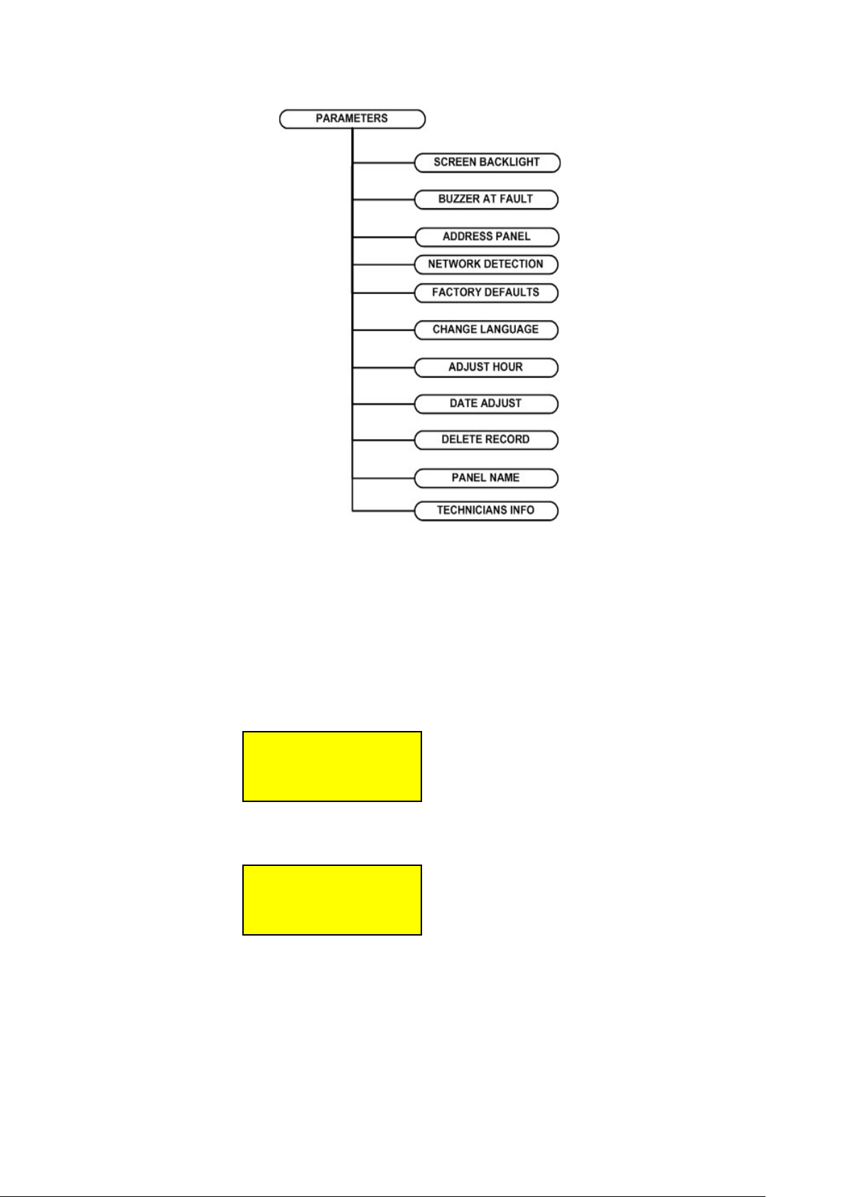
Figure 9: Parameters menu
The selections are:
SCREEN BACKLIGHT: “CONTINUOUS” means that the screen panel is lighting continually (this selection reduces
the autonomy of the system) “NO CONTINUOUS” means the backlight of the display will be ON when there are
events or one button is pressed.
BUZZER AT FAULT: “NO SOUND” no sound if there is a fault only on alarm. “SOUNDS” the panel buzzer sounds
on alarms and on faults.
ADDRESS PANEL: we can change the address of the panel
If we put address 0 the network is disabled. If the address is the panel is a master panel. If the the address is
from 2 to 16 the panel is a subpanel.
NETWORK DETECTION: if the panel is a master panel ( address 1) we can make a network detection.
FACTORY DEFAULTS: Load factory defaults to the panel.
CHANGE LANGUAGE: change the language of the screen ( Greek or English)
ADJUST HOUR : adjust the time of the panel
DATE ADJUST: adjust the date of the panel.
DELETE RECORD : this option deletes all the recorded events from memory.
PANEL NAME: the name of the panel with a maximum of 20 characters.
TECHNICIAN INFO: change the technician information with a maximum of 20 characters.
=== MODIFICATION ===
ADDRESS PANEL
[0..16]: 1
====================
PANEL IN NETWORK :
1 2 5
TOTAL ==> 3
Page 18 from 22 921316000_09_016
Page 19
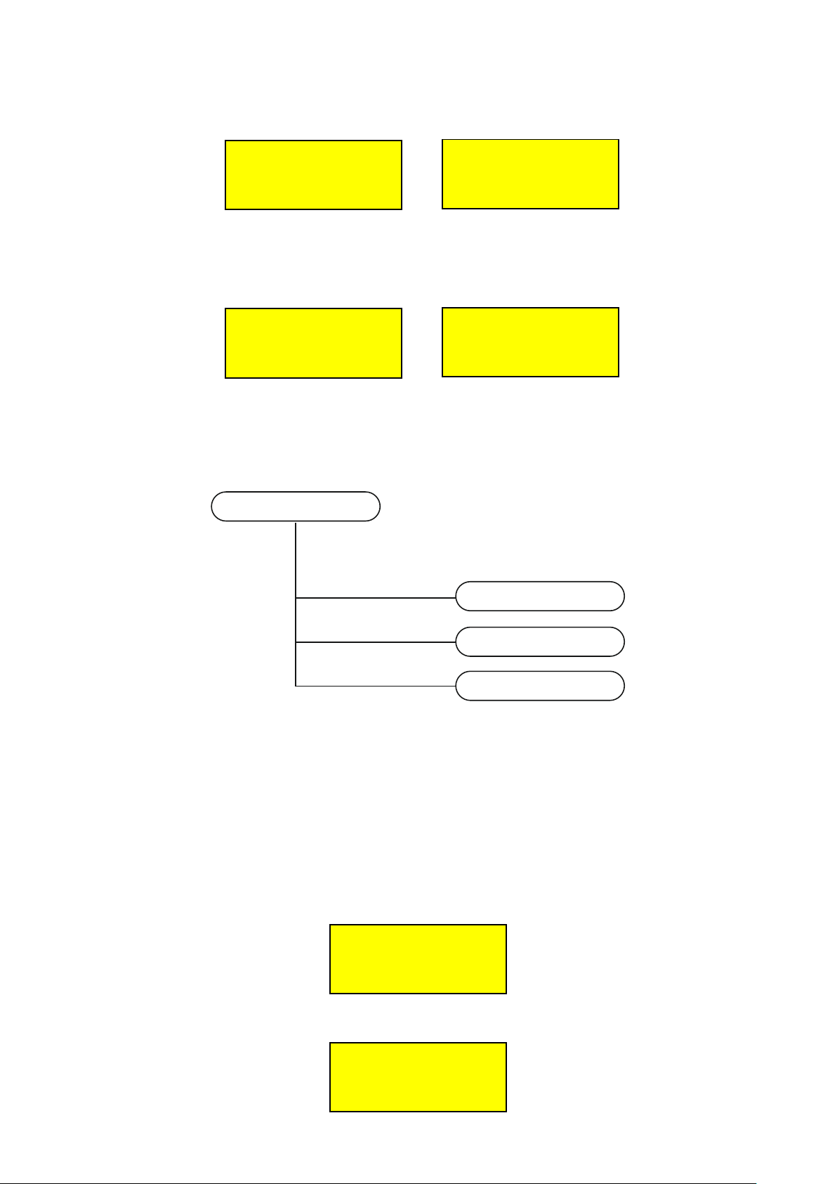
Enable menu
The enable menu is used to enable a sensor or all the sensors:
=== ENABLEMENT ====
ENABLE ALL SENSORS
SELECT → ENTER
====================
=== ENABLEMENT ====
ENABLE A SENSOR
SELECT → ENTER
====================
Disable menu
The disable menu is used to disable a sensor or all the sensors:
=== DISABLEMENT ===
DISABLE ALL SENSORS
SELECT → ENTER
====================
=== DISABLEMENT ===
DISABLE A SENSOR
SELECT → ENTER
====================
Check menu
This menu is used to check the hardware of the pane
l
CHECK
SENSOR
RELAY
LAMP TEST
Figure 15: Check Menu
On Check sensors the below screen appears
to see the other sensors press “3” or “4”
The screen to check the relay is
Page 19 from 22 921316000_09_016
1: I= 5,0 mA
2: I= 11,1 mA
3: I= 4,3 mA
4: I= 4,0 mA
====== CHECK ======
RELAY 1
STATUS ACTIVE
===================
Page 20

BS-316
To change the relay press button “3” or “4”. To change the status press button “ENTER”.
With lamp test you can test all the LEDs and LCD backlight for correct operation.
Useful notes to setup the panel BS-316
For the correct mounting and setup of the panel BS-316, the user must do some basic steps:
1) First of all, the technician has to design the schematic which includes the way of installation of the panel
and the devices, the length of the cable and the point where the device is connected. This diagram will be
useful for the fault detection (short-circuits, alarms and faults).
2) The user disables all the system.
3) Next the user configures the sensors and the inputs.
4) When finished the user enables the inputs that are required.
5) The panel must be isolated from the main power supply when we install the sensors. After all connections
are finished, the power to the panel is restored.
6) Leave the panel working for about 20 minutes without cutting off the power supply. Check the current of
every sensor. The current must not be over 4mA. If it isn’t, wait about 1 hour and then re-check. If the
current of the sensor is not about 4mA, then perhaps the sensor needs setup.
7) If there is one short circuit in the power supply of a sensor (terminals +,-) for a moment, the panel shows a
fault. To clear the fault first we have to correct the short circuit and then to reset the panel via the keyboard.
In case there is a fault you must check point to point, which is out of communication.
Technical Characteristics
Power Supply 220-240V AC / 50-60Hz
Consumption 60VA
Battery type 12V / 7Ah Pb or 2X12V/7Ah
Charge Circuit Power supply 13.8V / 500mA
Outputs 17 programmable relays (5Α/230VAC), Standard output 20V/300mA
Wrap protection class IP 30
Operating temperature range 5 to 40 oC
Humidity Up to 95% humidity
Dimensions 445 x 345 x 95 mm
Weight 6160 gr
Produced by ΕΝ 50270:2006, ΕΝ 60335-1:2012 +A11:2014 +AC:2014, EN 50194-1:2009
Warranty 2 years
Gas detection control panel up to 16 inputs
Page 20 from 22 921316000_09_016
Page 21

WARRANTY
Olympia Electronics guarantees the quality, condition and operation of the goods. The period of
warranty is specified in the official catalogue of Olympia Electronics and also in the technical le aflet,
which accompanies each product. This warranty ceases to exist if the buyer does not follow the
technical instructions included in official documents given by Olympia Electronics or if the buyer
modifies the goods provided or has any repairs or re-setting done by a third party, unless Olympia
Electronics has fully agreed to them in writing. Products that have been damaged can be returned to
the premises of our company for repair or replacement, as long as the warranty period is valid.
Olympia Electronics reserves the right to repair or to replace the returned goods and to or notcharge
the buyer depending on the reason of defection. Olympia Electronics reserves the right to charge or
not the buyer the transportation cost.
HEAD OFFICE
nd
72 . . . .
km O N R Thessaloniki-Katerini
P C P.O. Box 06 ginio Pierias Greece. . 60300 Ε
www.olympia-electronics.gr
[email protected]
Page 21 from 22 921316000_09_016
Page 22

1 2 3 4 5 6 7 8 9 10 11 12 13 14 15
16 Sensor’s Model
ZERO
RANGE
UNIT
Alarm
1
OUTPUT
1
Alarm
2
OUTPUT
2
Alarm
3
OUTPUT
3
1 2 3 4 5 6 7 8 9 10 11 12 13 14 15
16
DELAY ON
DELAY OFF
TIME ON
POSITIVE (YES
/NO)
LATCHED
Record Setup
We suggest completing the next tables for your setup and keep them for future reference.
Title : …................................................................................................................
Notes
................................................................................................................................................................................................................................................................................
................................................................................................................................................................................................................................................................................
................................................................................................................................................................................................................................................................................
................................................................................................................................................................................................................................................................................
................................................................................................................................................................................................................................................................................
................................................................................................................................................................................................................................................................................
................................................................................................................................................................................................................................................................................
Operator Code 1 1 1 1 Technicians Code 2 3 3 3
Page 22 from 22 921316000_09_016
 Loading...