

Page 1
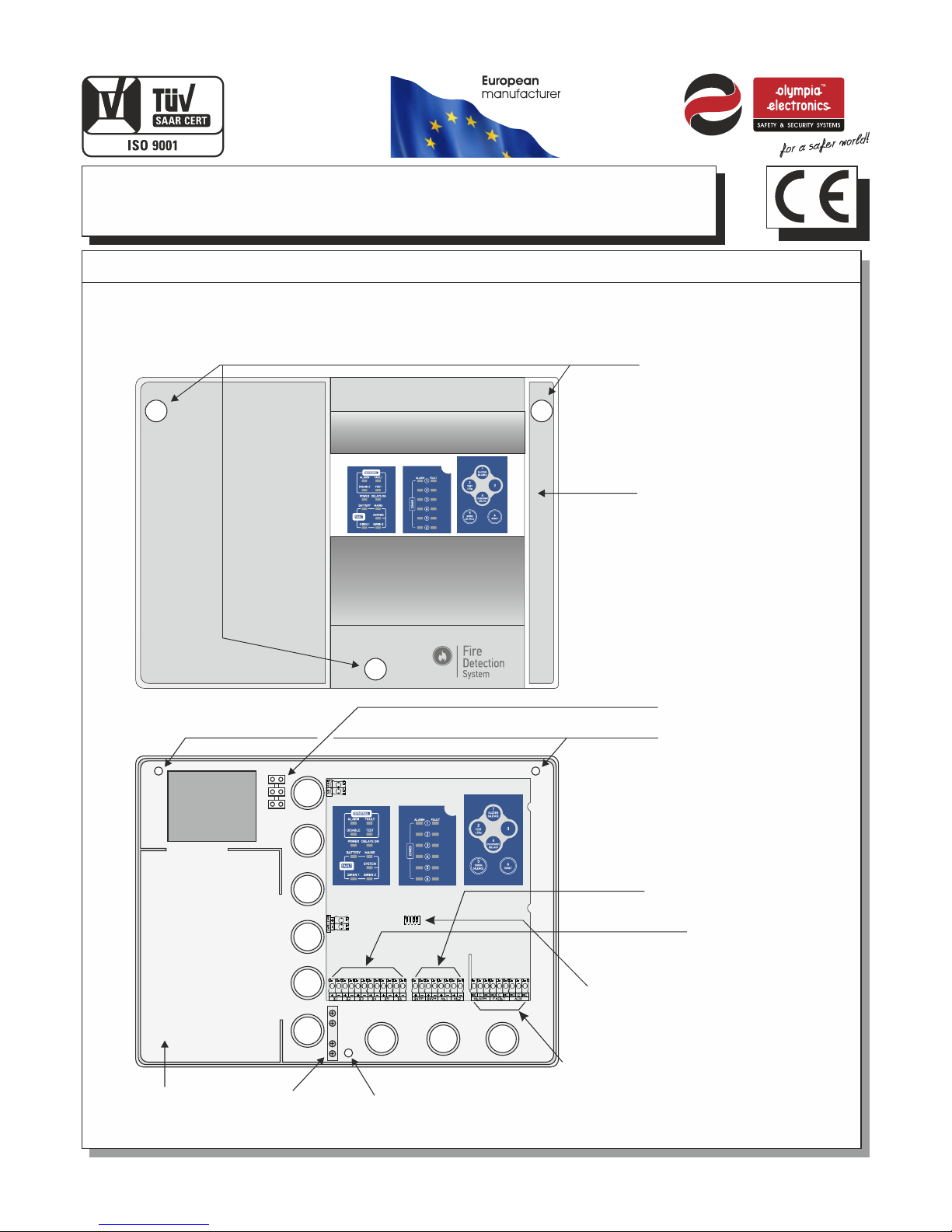
BS-1632, BS-1634, BS-1636
Conv en ti on al 2, 4 and 6 zone Fire Al ar m Pa ne ls
92116 3 6 0 0_ 0 9_ 0 22
GENERAL
The family of fire detection panels consist of 3 types (2, 4 and 6 zone) with identical operation and indications. The panels have
2 independent siren outputs, Alarm, Fault Relay and a programmable AUX relay. The required batteries for the panels are two
A-920 (12V/2.6Ah). All functions and indications are according to European Norms EN 54-2 and EN 54-4.
To p c o ve r
re t a in ing s c rew s
Co n t ro l Key b oar d a n d
in d i ca tio n l eds
Mo u n ti ng ho l es
Ba t t er y com p art m e nt
tw o Α- 9 2 0
MO D E s el ect i on
mi c r os wit c h
Re l a y ou tpu t s
co n n ec tio n t erm i n al s
Zo n e c on nec t ion t e r mi nal
Ge n e ra l out p ut co n n ec tio n
(S i r en s,2 4 V)
Ma i n s vo lta g e con n e ct ion
te r m in al bl o ck (2 2 0 -2 40V AC )
Figure 1. S chematic diagram of the panel
Mo u n ti ng ho l e
Ex t r a ea rth
te r m in als
Page 1 fr o m 1 0
Thank you for your trust in our products
Olympia Electronics - European manufacturer
Page 2
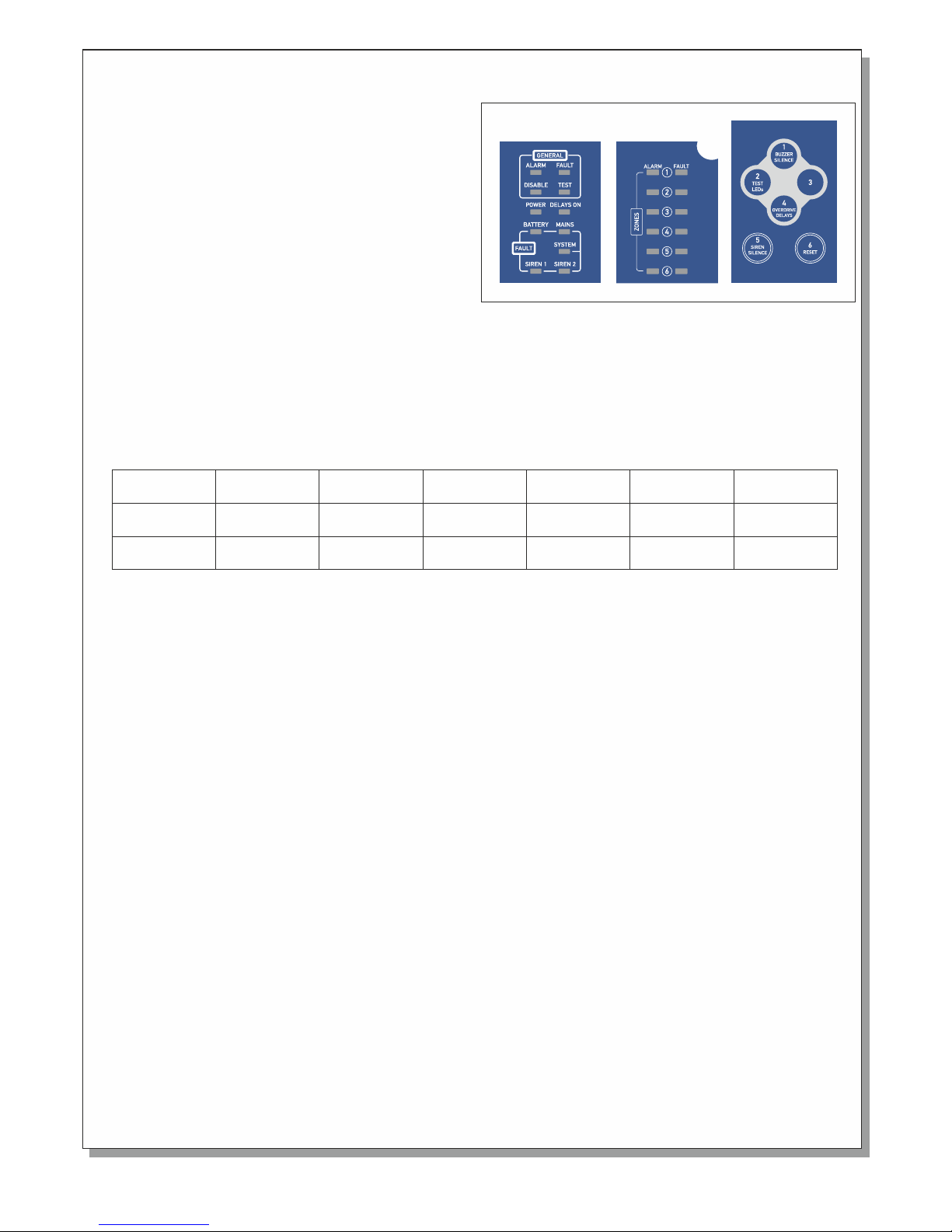
Indic at ion LED d escri pt ion
The schematic shows the control keyboard and the
indication plate of a 6 zone BS-1636 panel. Starting from
the top left side we can see 4 indicators marked
'General'.The 'Disable' LED lights in every DISABLE
condition.
The 'Test' LED lights in every TEST condition .The panel
does not have a test condition as specified in paragraph
11 of EN 54-2.
The 'Fault' LED lights in every FAULT condition. Blinks
when we have a FAULT condition and the buzzer is
silenced. The 'Alarm' LED lights when we have an ALARM
condition. Blinks when we have an ALARM condition and
the buzzer is silenced.
Below is the indicator “POWER” which is on when the panel is working and blinks when there is mains supply
failure.
On the right of the “POWER” indicator is the “Delays ON” indicator which shows if the delays of the output are
enabled or disabled.
Below the `General` indicator group we can find the indication group called `Fault`.
The 'Battery ' LED and 'Mains' LED in combination, show us faults concerning the power supply. These
combinations are shown in the panel below.
The 'System LED lights to indicate a problem with the main processor unit (System fault).
BATT E RY Faul t
MA I N S F a u lt
La c k o f
AC v o l t a g e
Ba t t e r y
Ov e r c h a rging
Ba t t e r y
Di s c h a r ged
Ba t t e r y
Ab s e n t
Ch a r g e r
Er r o r
Lights
----
Lights
Lights
Lights
Blinks
Blinks
Lights
Blinks
Blinks
The LEDs marked 'Siren1' and 'Siren2' correspond to the siren outputs. If a siren out has a short circuit or open circuit
then the corresponding LED will blink. If a siren is disabled the corresponding LED will light.
The next group of indicators is the 'Alarm' indication LEDs.
These indicators light when a corresponding zone issues an ALARM condition. Next to this group we have the
'Fault/Disable' indication for each zone. When the panel monitors an open or short circuit condition in a zone then
the corresponding LED will blink. If a zone is disabled the corresponding LED will light.
Contr ol k eyboa rd desc ri ption /operat ion
The panel is controlled/ operated using the six numeric keys (1 to 6) found on the front panel. When a key is pressed a
short tone is issued.
The panel has three access levels.
Access level 1:
has all the functions that can be done directly from the user without using a code. These operations are:
Buzzer silence / Buzzer reactivation: If an alarm of fault condition is issued then the internal buzzer will sound.
Pressing the key "1" will silence the buzzer. ( The buzzer sounds periodically once every minute.) Pressing this key
again will reactive the buzzer.
Lamp test: Pressing the key "2" a lamp test is conducted by lighting the LEDs. The panel then returns to normal
operation. The above tests can be conducted only if the panel is in quiescent state (No fault or alarm conditions).
Override Delays: If an alarm occurs and the delays are active the user can overrride the delays by pressing the key “4"
. The output will be immediately activated.
Page 2 fr o m 1 0
Ba d
Ba t t e r y
----
Lights
92116 3 6 0 0_ 0 9_ 0 22
Page 3

Access level 2:
Includes all the functions that the user can do and an access code is required. The code is "34”, it is the same for all
panels and can not be changed. The functions that can be implemented using this code are the following:
Evacuate: Gives evacuate signal to the panel.
The user must enter the user code ( 34) and then the keys '4' and '4'. Then the panel will go to alarm state. The sirens
will sound and the internal buzzer also.
Siren Silence: When an alarm is issued and we want to silence the sirens then we must enter the user code
( 34 ) and then the keys '5' and '5'. The sirens are silenced but the internal buzzer continues to sound. The panel
remains in normal operation. A new alarm from another zone will resound the sirens. To resound the sirens press again
the same code.
Panel Reset: When an alarm or fault condition has occurred and we want to reset the panel we must enter the user
code (34) and then the keys '5' and '6’. The panel lights all LEDs in sequence and then enters normal operation.
Zone enable/disable: If we want to disable the operation of specific zones then we must enter the user code
( 34 ) and then the keys number '5' and '4'. The LED marked 'General disable' start to blink, and if a zone is disabled the
corresponding 'Fault' LED lights to indicate this. Using the keys 1, 2, 3, 4, 5 and 6 we can enable or disable the
respective zones. The disabled zones light the corresponding LED. The panel exits this mode if no key is pressed for
more than 30 seconds. The panel then conducts an automatic RESET and enters normal operation mode. Disabled
zones does not give alarm or fault condition. If we have disabled zones then this is indicated with the indicators 'General
disable' and the corresponding Disable LED zone and the buzzer sounds once every minute.
Siren enable/disable: If we want to disable the operation of specific sirens we must enter the code (34) and then the
keys '6' and ‘6’. The LED marked 'General Test' start to blink, and if a siren is disabled Siren1 LED lights for siren 1 and
Siren2 LED lights for the siren 2. Using the keys 1 and 2 we can enable or disable the respective sirens. The disabled
sirens have a LED lighted. The panel exits this mode if no key is pressed for more than 30 seconds. The panel then
conducts an automatic RESET and enters normal operation mode. All disabled sirens are supplied with the proper
voltage but the panel can not enable them or read their condition. If we have disabled sirens then this is indicated with
the indicator 'General disable' and the buzzer sounds once every minute.
Delays ON/OFF: If we want to disable the delays of the outputs. We must enter the code (34) and then the keys '6' and
‘4’. Then the delays will be disable, the LED marked “Delays ON” will turn off. To enable the delays we must press again
the code.
Page 3 fr o m 1 0 92116 3 6 0 0_ 0 9_ 0 22
Access level 3:
These functions are implemented during the installation and need the technical code to be accessed. The technical
code is "364", it is the same for all panels and can not be changed. These functions can be implemented using the
technical code are activation methods used for the relays and can be done only if the panel has not issued an alarm or
fault condition. These functions are ancillary and not required by the EN 54-2.These methods of programming are:
AUX RELAY programming: If we want to program the operation behaviour of the AUX RELAY we must enter the
technical code ( 364 ) and then press the key '5'. The 'General fault' and 'General alarm' LEDs start to blink. The Alarm
zone LEDs and the fault LED zone show the way the AUX RELAY . If the Alarm led of the zone is on then we have logic
AND for the aux relay activation. If the fault led of the zone is on then we have logic OR for the aux activation.
For example if Alarm Zone 1 and 2 is on and Fault Zone 3 and 4 is on, then the relay will be activated when Z1 and Z2 is
in alarm condition or Z3 or Z4 are in alarm condition
To change the state of each zone, press the corresponding number each time.
In order to exit this programming mode and to store the settings in memory do not press any key for more than 30
seconds. This system will conduct an automatic RESET and will enter normal operation mode.
Page 4
Page 4 fr o m 1 0
RESOUND sirens: It is possible to configure to automatically resound the sirens following an alarm in another zone.
You must enter the technical code (364) and then press the key '4'.
The 'General fault' ,'General Disable' and 'General alarm' LEDs start to blink. The Alarm LED of zone 2 led is off the
sirens resound following an alarm in another zone else if the led is on the sirens does not resound. By pressing the key
'5' you can change the configuration.
Programming the delay of general relay (AUX RELAY). If you want to program the delay of the AUX RELAY must
enter the technical code ( 364 ) and then press '6' . The LED " General fault " ," General Alarm " and “DELAYS ON”
begin to blink .
The indicative Zone " Alarm" and " Fault LED” indicates delay activation of “AUX RELAY”.
To change the mode press ' 1 ' 2' , ' 3' and '4'. To exit the programming mode and store the settings in memory , press the
button <5 > . The system will automatically RESET and will enter normal operation.
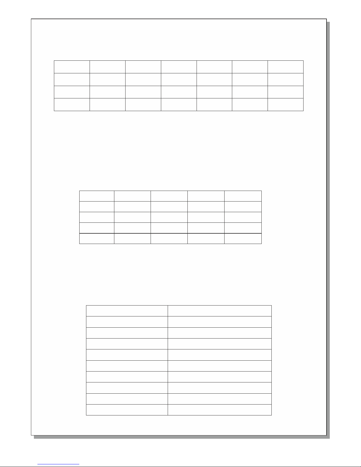
Below is a table that summarizes all the code and corresponding functions.
92116 3 6 0 0_ 0 9_ 0 22
Fa u l t z o n e 1
Al a r m z o n e 2
Al a r m z o n e 1
Wi t h o ut
De l a y
30 s e c o n d
De l a y
60 s e c o n d
De l a y
90 S e c o n d
De l a y
LED ON
LED OFF
LED OFF
LED OFF
LED OFF
LED OFFLED ON
LED OFF LED OFF
LED OFF LED ON LED OFF
Fa u l t z o ne 2
LED OFF LE D O F F L E D O F F L E D O N
Code
3-4-4 - 4
3-4-5 - 4
3-4-5 - 5
3-4-5 - 6
3-4-6 - 4
3-4-6 - 6
3-6-4 - 5
3-6-4 - 4
3-6-4 - 6
Evacu a t e
Enabl e / D is a bl e Z on e s
Funct io n
Silen c e / Re s ou n d Si r en s
Reset
Delay s O N / OF F
Enabl e / D is a bl e S ir e ns
Progr a m AUX rel a y
Resou n d a n d De l ay s i re n s
Progr a m P r ed e la y o f AUX Re l a y
Fa u l t z o n e 1
Fa u l t z o n e 2
Al a r m z o n e 1
Ze r o
De l a y
De l a y
1m i n
De l a y
2m i n
De l a y
3m i n
De l a y
4m i n
De l a y
5m i n
LED ON
LED Off LED Off
LED Off LED Off LED Off LED Off LED On
LED Blink
LED Off LED Off LED Off LED Off
LED Off LED OffLED On
LED Blink
LED Blink
Program Siren delay. If we want to program the delay of the sirens we must enter the technical code ( 364 ) and then
press the key '4'. The 'General fault', 'General Disable' and 'General alarm' LEDs start to blink. The Alarm, the
Fault/Disable LED of zone 1 and Fault/Disable LED of zone 2 show the programmed delay of the sirens according to the
table below. By pressing the key '1' you can change the configuration.
Page 5
Conne ct ions
The three panels of the family have the same connections. The main differences in these panels is the number of the
available zones and the number of the relays zones. The common outputs, the maximum consumption and the
operation procedures are identical for all the panels.
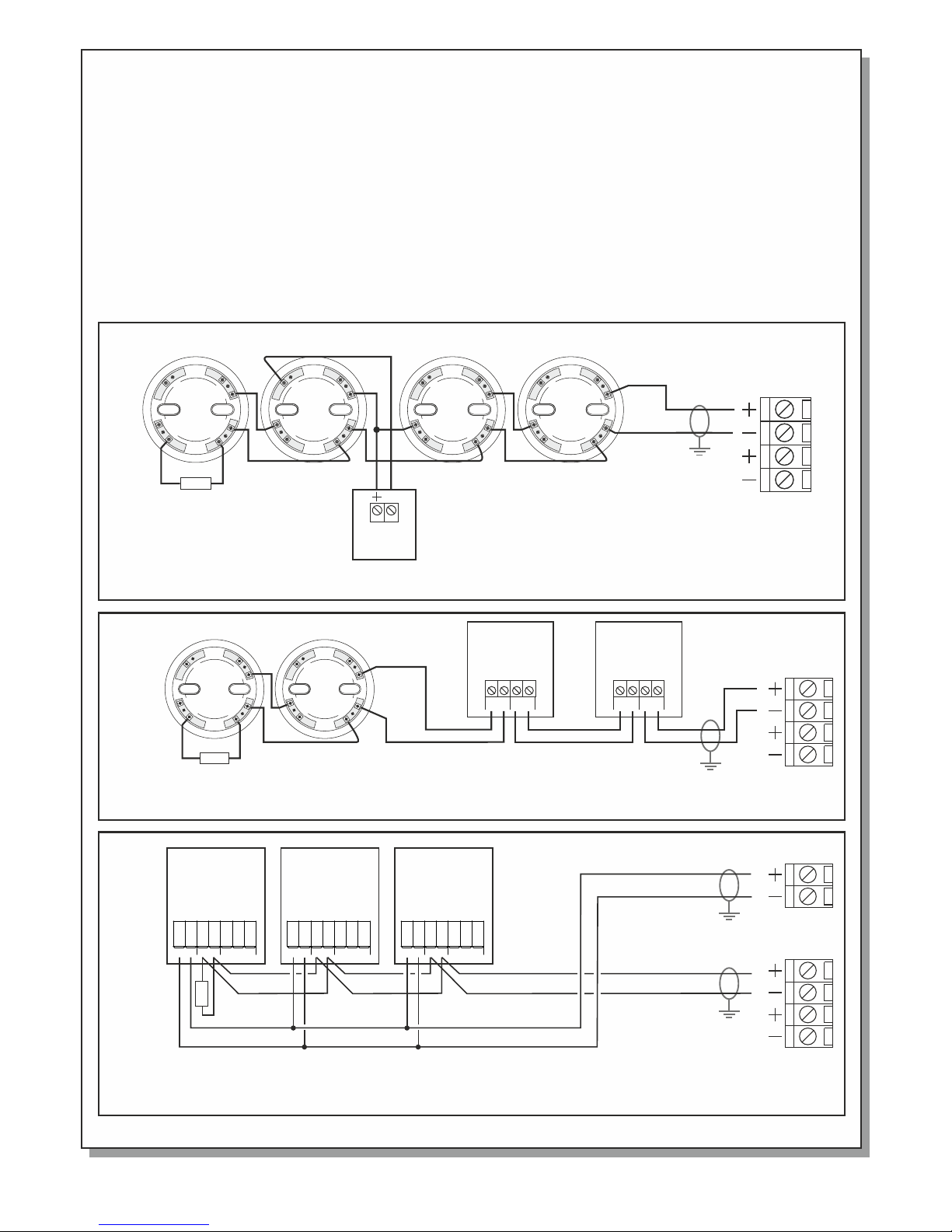
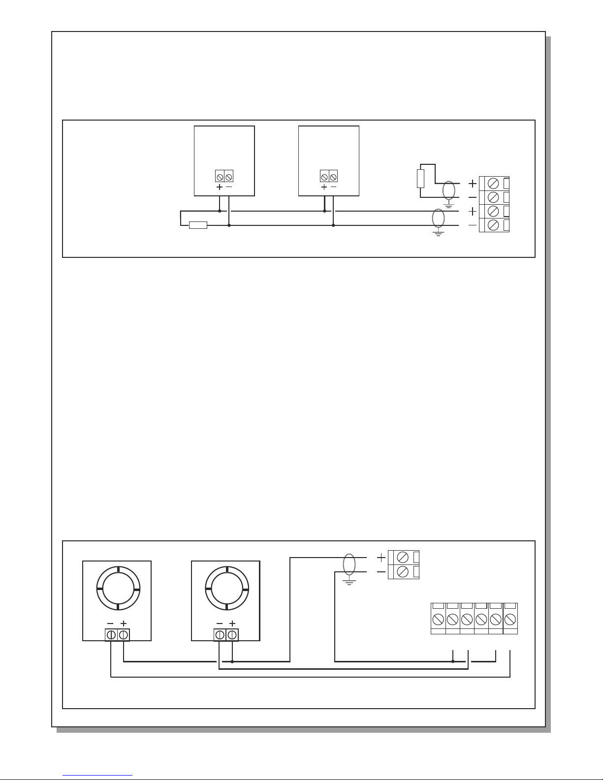
Connecting detectors and break-glass call points to zones
By default each zone terminal block has a preinstalled terminal resistor (8Κ2). This resistor must be removed and
installed on the last device of the zone or is left connected on the zone terminals if the zone is not used. The connections
to all the zones are identical. What is shown in figures 2, 3 and 4 for zone 1 is valid for all the zones.
The total number of connected devices per zone is 20.
All cable zones must be insulated, to earth ground, to meet EMC requirements.
The cable length for each zone must not exceed the 1.5 kilometres with a cross section cable of 1.5mm².
Page 5 fr o m 1 0
Figur e 2. Connec ting 4 dete cto r base s to zo ne 1. Each ba se can acce pt BS-655 , BS-660 or B S-657
detec tors. A re mote indi cation LE D BS-572 is c onnecte d to one of the d etector s.
Figure 3. Connecting 2 ca ll poi nts BS -536 a nd 2 det ecto r base s to the s ame zo ne.
Figur e 4. Connec tin g 3 Gas detec tors BS-6 85 or BS-68 6. Beside s the c onne cti ons to the zo ne termin als
these d etector s mus t also be con nected to t he termin als 24V_M i n ord er to be s upp lied with p ower.
Ζ1 Ζ2Ζ1 Ζ2
8Κ2
BS-572
remote
LED
R
Terminal
resist or
Ζ1 Ζ2
Break-glass
call point
BS-536
OUT IN
Break-glass
call point
BS-536
OUT IN
Detect or
base
Detect or
base
Detect or
base
Detect or
base
8Κ2
Terminal
resist or
Ζ1
24 V _ M
Ζ2
8Κ2
Terminal
resist or
ZO N E
10 - 30 V
NCNO C
BS-685
Gas
Detector
ZO N E
10 - 30 V
NCNO C
BS-685
Gas
Detector
ZO N E
10 - 30 V
NCNO C
BS-685
Gas
Detector
-R
O
U
T
-
-
L
N
I
T
+
U
R
O
N
+
L
I
-R
O
U
T
-
-
L
N
I
T
+
U
R
O
N
+
L
I
-
R
O
U
T
-
-
L
N
I
T
+
U
R
O
N
+
L
I
-
R
O
U
T
-
-
L
N
I
T
+
U
R
O
N
+
L
I
-
R
O
U
T
-
-
L
N
I
T
+
U
R
O
N
+
L
I
-
R
O
U
T
-
-
L
N
I
T
+
U
R
O
N
+
L
I
Detect or
base
Detect or
base
92116 3 6 0 0_ 0 9_ 0 22
Page 6
Besides the terminals that we re des crib ed up to n ow the p anel a lso ha s the fo llow ing ou tput s :
24V_M: A 24VDC output tha t is inte rrupted in the even t of a pane l reset. It is mainly us ed for powering gas
detectors or other devices t hat need an inte rrup ted power sup ply whe n the pan el is resetting. If this output
is short circuited then the LED m arke d 'Gen eral f ault ' is lig hted .
24V_P: A 24VD C power ou tput that is no t interrupte d in the event of a r eset. It can be us ed to po wer
electromagnetic door latc hes.
Relay Alarm : Voltage free relay con tact s are ac tiva ted wh en the re is an a larm c ondi tion .
Relay Fault : Voltage free r elay c onta cts ar e deac tiva ted wh en the re is an f ault c ondi tion .
Relay AUX : Voltage free relay conta cts th at by de faul t when o ne zon e is in al arm co ndit ion.
ATTENTION: T he relays are ra ted at 30 VDC and 5A maximum. N o 2 30VAC signals can be c onne cted
to these relays.
Sir en - Sou nder C onne ctio ns
Each panel offers 2 independent circuits for connecting sirens, bells or other devices that need 24VDC in order
to operate. Each circuit can supply a maximum of 300mA. Each terminal block by default has a pre-installed
terminal resistor (8Κ2). This terminal resistor is either removed and installed on the last siren of the line or is
left on the terminal block if the circuit is not used.
The connections of both circuits are identical.
Figure 5. Connect ing 2 BS -531 s iren s to the AL ARM 2 ou tput . Thi s conn ecti on req uire s pola rity.
BS-531
Siren with
Beacon
BS-531
Siren with
Beacon
8Κ2
AL ARM 1 A LA RM2
8Κ2
Termi nal
Res istor
Termi nal
Res istor
Figure 6. Connecting 2 electr omag neti c door l atch es BS- 510/ 24 to th e pane l.
AL ARM FAU LT
24 V_P
C C
NO NONC N C
24 V D C 24 V D C
BS-5 1 0 /2 4BS-5 1 0 /2 4
Page 6 fr o m 1 0 92116 3 6 0 0_ 0 9_ 0 22
Page 7
Installation
The ins t a l la t io n o f th e p an e l mu s t be c a rr i ed o u t by q u al i fi e d pe r so n ne l o nl y.
Disco n n e ct p o we r b ef o re s e rv i ci n g.
Never i n s e rt o r r em o ve b o ar d s or c o mp o ne t s wi t h th e p ow e r on .
Durin g i n s ta l la t io n u se g r ou n de d a nt i st a ti c w ri s t ba n d to p r ot e ct t h is e q ui p me n t fo r m ES D .
The pan e l m u st b e i ns t al l ed p e rm a ne t ly. I t is n o t al l ow e d to c o nn e ct t h e de v ic e d ir e ct l y to a n y so c ke t outle t .
Mount i n g t h e pa n el t o t he w a ll
The sit e c h o se n f or t h e lo c at i on o f t he p a ne l s ho u ld b e c le a n an d d ry a n d no t s ub j ec t t o sh o ck o r
vibra t i o n.
In page 1 s h o w s th e m ou n ti n g ho l es o f t he p a ne l .
The pan e l m u st b e p la c ed a b ov e 1 m fr o m th e f lo o r an d a nd 1 m b el o w th e c ei l in g a nd m u st h a ve
dista n c e 3 0c m f ro m a ny o t he r d ev i ce s . No o t he r p ow e r li n es m u st p a ss b e hi n d th e p an e l, o n ly t h e
suppl y c a b le s o f th e p an e l.
Cabli n g
In orde r t o m e e t EM C re q ui r em e nt s , c on n ec t io n s of p e ri p he r al s t o th e p an e l mu s t be d o ne u s in g
shiel d e d c ab l es .
Each sc r e e n or s h ie l d br a id m u st p r op e rl y b e co n ne c te d t o th e e ar t h te r mi n al b l oc k p ro v id e d, t h us
ensur i n g t he s h or t es t p os i bl e p at h . Th e m ax i mu m c on d uc t or d i am e te r s iz e , wh i ch c a n be u s ed , i s
2,5mm ²
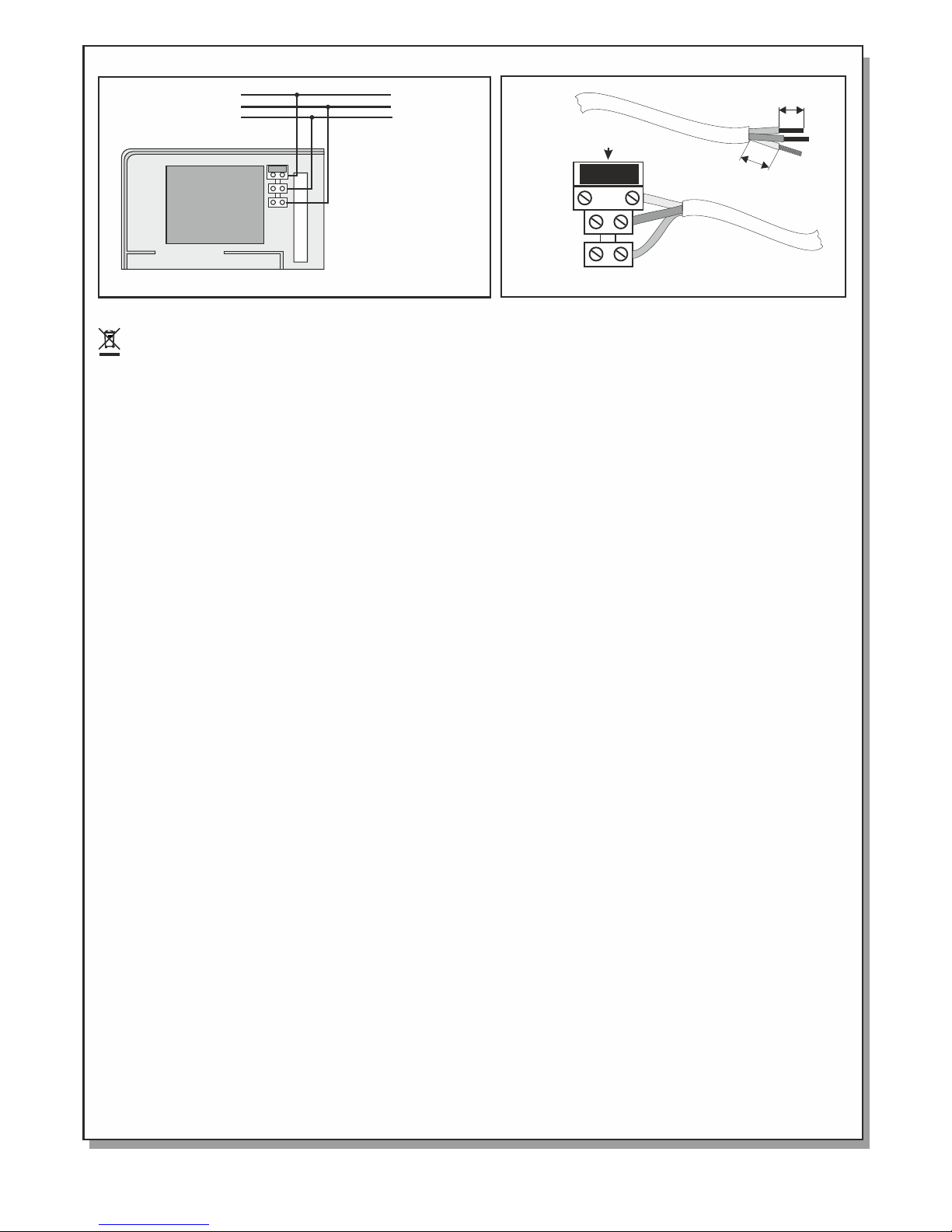
Conne c t i ng t h e m ai ns p o we r s up p ly ( 22 0 -2 4 0V AC)
The pan e l h a s ho l es o n t he b a ck s i de f o r al l t he w i ri n g to p a ss t h ro u gh . Yo u c a n c on n ec t c ab l es w i th
max. co n d u ct o r di a me t re o f 2 .5 m m to t h e pa n el s t er m in a l bl o ck s .
The mains power supply wiring must use a double insulation cable.
The main supply must include an earth conductor connected to the fixed installation
earthing system of the building. The connection with the mains power supply must be
done to the terminal blocks located on the panels up left area Figure 8 .
Bat tery c onne ctio n
The bat t e r y co m pa r tm e nt h a s th e a pp r op r ia t e di m en s io n s fo r Α -9 2 0
batte r i e s of O l ym p ia E l ec t ro n ic s .
The charg i n g un i t on PCB is a ls o ca l c u la t ed for the speci f i c ba t t e ri e s.
Repla c e the m only with batte r i e s of the same type .
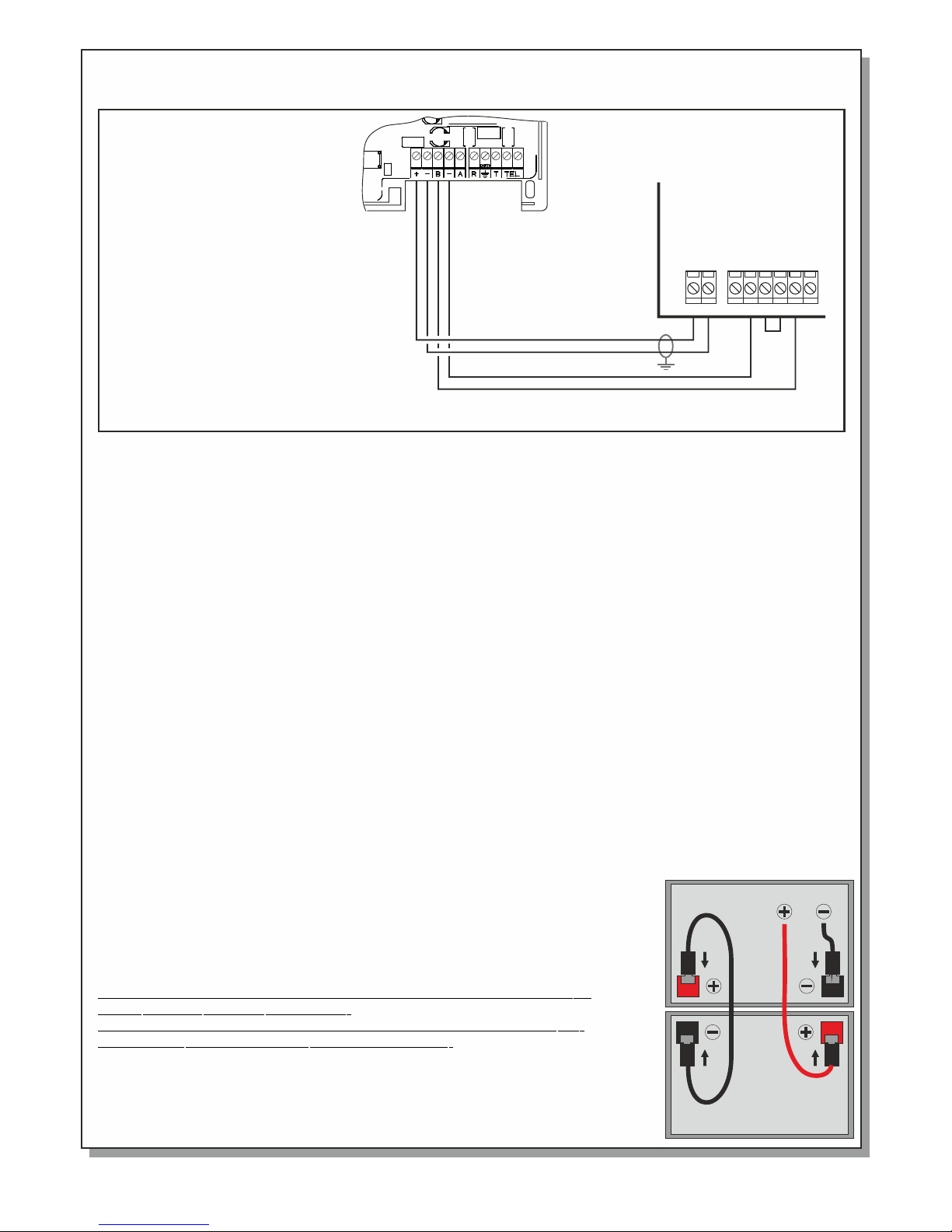
From th e P C B , a re c o nn e ct e d tw o b at t er y w ir e s wi t h a sp e ci a l te r mi n al o n t h e
edge. The y mu s t be conn e c t ed to the two ba t t er y poles . Co n ne c t t he black wi r e
to the ne g a t iv e p ol e (m a rk e d (- ) o r a bl ac k m ar k) , t he r e d wi re t o p os i ti v e po le
(mark e d (+) or a r ed mark) an d connec t th e inclu d e d wire fo r the lin k as showe d
in t he sid e figu r e .
Figur e 7 . C o n ne c ti on d i a gr a m of B S- 4 89 t e le p ho n e op e ra t or .
-
+
24_P
Fir e Dete ctio n
Pan el
Connecting the BS-489 telephone operator
Page 7 fr o m 1 0
NO
ALARM
C NC NO
FAULT
C NC
Pan e l conn ecti on
Lin k
92116 3 6 0 0_ 0 9_ 0 22
Page 8
Bat tery dis posa l
I s no t allow e d to d i s ca r d batt e r i e s into c om m on tras h bins, t he y mu s t be d i s ca r de d onl yt i in
batte r y rec y c l in g poi n t s .
Wa rnin gs
1. Serv i c e a nd m a in t en c e ac t iv i ti e s sh o ul d b e do n e on l y wh e n th e d ev i ce i s d is c on n et e d fr o m
the mai n s p o w er s u pp l y an d t he b a tt e ry.
2. Duri n g t h e i ns t al l at io n t h e co n ne c ti o ns t o t he m a in s p ow e r su p pl y a nd t h e ba t te r y mu st b e
done af t e r a l l ot h er c o nn e ct io n s a re f in i s he d.
3. The pa n e l c o nn e ct io n w i th t h e ma i ns s u pp l y mu s t be d o ne v i a a1 0 A exte r n a l fu s e or a n
autom a t i c c ir cu i t br e ak e r ra t ed a t 1 0A . Th i s fu s e ha s t o be a s e pa r at e , la b el e d fu s e.
4. Al w ay s u se c a bl e s wi t h do u bl e i ns u la t io n .
5. The di a m e te r o f th e c ab l e mu s t be a t l ea s t 1m m .( F ig u re 9 )
6. The in n e r i n su l at i on o f e ac h c ab l e mu s t no t b e cu t m or e t ha n 1 cm ( Fi g u re 9 )
7. The ou t e r i n su l at io n m u st n o t be c u t mo r e th a n 1c m a wa y fr o m th e i nt e rn a l in s ul a ti o n.
8. The pa n e l ' s in t er na l f u se i s T 63 0m A L2 5 0V w i th 5 x 20 d i me n si o ns .
9. The ba t e r y fu s e is a r e se t ab l e fu s e 90 0 mA ins i d e t he p a ne l .
Ini tial I nsta llat ion
When the connections to zones, sirens and other required outputs are fi n i s h e d t h e n w e m u s t c o n n e c t t h e m a i n s
power supply. In order to aid the installer during the in i t i a l i n s t a l l a t i o n , t h e p a n e l o f f e r s a s p e c i a l c o n f i g u r a t i o n .
This configuration is entered by setting MODE switch 1 to the ON position. Af t e r e n t e r i n g t h i s m o d e t h e p a n e l
conducts an auto reset and the 'Power', 'Zone disable' and 'General di s a b l e ' L E D s b l i n k . The special func t i o n s
that aid in working out various problems that might arise are:
When a zo ne ha s an open cir cui t the n the internal buzzer s oun ds an d the correspo ndi ng LE D lig hts. If the
problem is corrected th en th e buz zer i s dea cti vat ed an d the L ED is t urn ed off.
When a z one h as a short cir cui t the n the i nte rna l buzzer sounds and th e cor res pon din g LED b lin ks. I f the
problem i s corre cted then th e buzze r is d eac tiv ate d and the LED is turn ed off.
When a s ire n outp ut has an open ci rcu it the n the int ern al buz zer is activated and the corr esp ond ing faul t LED
lights. I f the probl em is cor rec ted the n the buzze r is d eac tiv ate d and the LED is turn ed off.
When a siren output has a sho rt ci rcu it th en th e internal buzzer sound s and the correspon din g LED blinks. If the
problem i s corre cted then th e buzze r is d eac tiv ate d and the LED is turn ed off.
When a ba tte ry fault exists t hen the 'Batt fault' LED lig hts and th e 'P owe r fa ult ' LED b lin ks. If the problem is
corrected th en th e LEDs ar e deact iva ted .
If all th e pro ble ms are cor rec ted an d the inst all ati on is op era tin g nor mal ly then the MOD E swi tch 1 mu st be placed
in the OFF position. The panel con duc ts an aut o-r ese t and is ready fo r operation.
Walk - Testing
By using a spe cia l ope rat ion mode we can con duc t a walk test of the sys tem . To ente r wal k-t est mode set th e MOD E swi tch
1 to the ON position. The 'Power', 'Zon e disa ble ' and 'Gen era l disa ble ' LEDs bli nk. If an alarm is man ual ly given by eith er
activating a BS-536 c all p oin t or by activating a smo ke detect or wi th smoke or s imulated smo ke pa rti cles t he
corresponding Al arm LED of the zon e will lig ht and the siren will sou nd for 2 secon ds. Usi ng this me thod we can test the
operation of t he zo nes .
Aft er finishing the walk test set the MODE sw itc h 1 t o the OFF position. The pane l conducts an autom ati c res et and ent ers
normal op eration mode.
Optional Function of EN 54-2.
The o ptional fu nction whi ch i s pr ovi ded by t he panel is th e fi re a lar m de vic es p ara gra ph 7 .8 of EN 54 -2 a nd d ela ys t o
outputs (paragraph 7. 11 of E N 54- 2).
Design
Components o f the panels have bee n selected for the intended purpo se, a nd are expected to opera te within t hei r
specification wh en th e env iro nme nta l con dit ion s out sid e the c abinet of the panel comply with cl ass 3 k5 of
EN 60721-3-3:199 5.
Figure 8. Panels c onnection with 220-240V AC
220- 2 40 V AC
L
N
1 cm
Fuse: T630mAL250V (5x20)
1 cm
Figure 9. Panels connection w ith 22 0-24 0V AC
PE
Page 8 fr o m 1 0 92116 3 6 0 0_ 0 9_ 0 22
Page 9
Page 9 fr o m 1 0
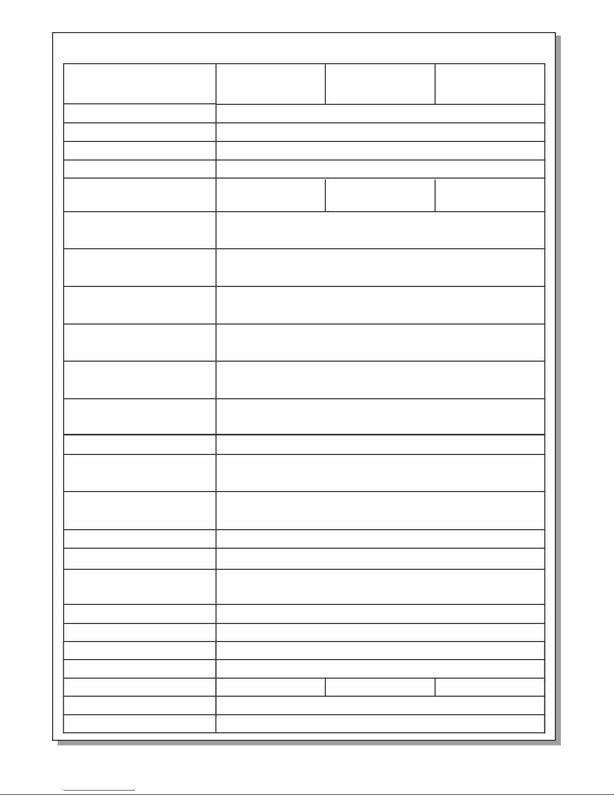
Tec hnica l Specifi catio ns
BS- 1634
4 zo n e f i r e
de t e c t i on pane l
BS- 1636
6 zo n e f i r e
de t e c t i on pane l
Mains p o w e r su p pl y 22 0 - 2 4 0 V AC / 50-6 0 H z
Two 12V Le a d a c i d s ealed 2 . 6 A h
St a b i l i zed pow e r s u p ply 27. 6 V / m a x . 4 00mA
Two 24V ci r c u i t s that a r e m o n i tored f o r o p e n a nd shor t c i r c uit con d i t i o ns
(m a x i m u m curre n t 3 0 0 mA ea c h). Eac h o u t p u t is prot e c t e d
wi t h a s e l f -rese t i n g e lectr o n i c f u se.
24 V D C ( ± 3 V DC) per m a n e nt outp u t w i t h m aximu m c u r r e nt outp u t 0 . 3 A
Th e o u t p u t is prot e c t e d with a se l f - r e setin g e l e c t ronic f u s e .
AB S - p o l y c arbon a t e
Consu m p t io n
Batte r y t y pe
Charg i n g c ir c ui t
Zone ci r c u it s
Alarm c i r c ui t s
Outpu t 2 4 P
Const r u c ti o n ma t er i al
2 ci rcuit s mon ito red for
sh ort and o pen c irc uit
co nditi ons ( max imum cu rre nt 35 mA)
24 V D C ( ± 3 V DC) res e t i n t errup t e d o u t put wit h m a x i m um cur r e n t o u tput 0. 3 A
Th e o u t p u t is prot e c t e d with a se l f - r e setin g e l e c t ronic f u s e .
Outpu t 2 4 M
Th r e e r e l ays con t a c t s are rat e d a t 3 0 V DC and 5A maxim u m
ea c h . U n d er no cir c u m s tance s s h o u l d volta g e s o r c u rrent s o u t s ide lim i t s
be c o n n e c ted. All rela y s o u t put mus t b e p r o t ected w i t h a f u se of the s a m e r a t ing.
Outpu t s R e la y s
32 5 x 2 4 0 x 8 5 m m
ΕΝ 5 4 - 2 , Ε Ν 5 4-4
2 ye a r s
Dimen s i o ns
We ig h t
Produ c e d i n ac c or d an c e to
Guara n t e e
Up t o 9 5 % r e l ative h u m i d ity
Humid i t y
o
0 to 5 0 C
Opera t i o n te m pe r at u re
Th e t o t a l o utpu t c u r r e nt ( zone s c i r c u its, si r e n c i rcuit , o u t p u ts 24P, 24 M)
mu s t n o t e x ceed 60 0 m A .
(I m a x A = Ima x B = 6 0 0 mA, Imi n = 3 0 m A )
Total l o a d
IP 3 0
1O h m
90 0 m A
21 V
Ca b l e s f o r fire ra t e d c a bles sy s t e m s s uch a FIP 2 0 0 , M ICC, P Y R O F I L
Th e p a n e l h as only o n e s e r vicea b l e f u s e to prot e c t i n c oming m a i n s s upply.
Th i s f u s e i s 6 3 0 mu s t b e r e p laced w i t h a f u se T mA L 2 5 0 V
of t h e s a m e t ype and r a t i n g
IP
Batte r y m a xi m um i n te r na l
resis t a n ce R i ma x
Batte r y c u t of v o lt a ge
Maxim u m c u rr e nt
batte r i e s di s ch a rg e
Cable s
Fuse ra t i n gs
4 ci rcuit s mon ito red for
sh ort and o pen c irc uit
co nditi ons ( max imum cu rre nt 35 mA)
6 ci rcuit s mon ito red for
sh ort and o pen c irc uit
co nditi ons ( max imum cu rre nt 35 mA)
50 VA
Auton o m y
72 hour s ( M a xi m um c o nn e ct e d de t ec t or s 7 2 an d
no load a t o u t pu t 2 4V M a nd 2 4 VP )
BS- 1632
2 zo n e f i r e
de t e c t i on pane l
92116 3 6 0 0_ 0 9_ 0 22
13 6 0 g r ( 3 080gr w i t h b a ttery ) 13 5 0 g r ( 3 070gr w i t h b a ttery ) 13 4 5 g r ( 3 065gr w i t h b a ttery )
Page 10
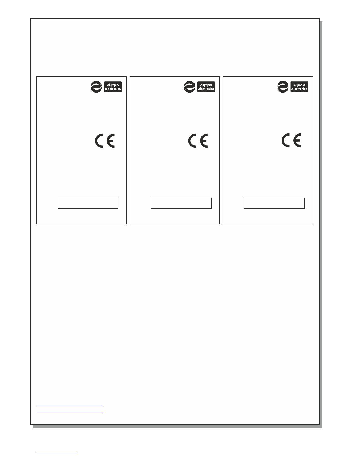
Certi fi catio n
The pan e l s B S -1 63 2 , BS - 16 3 4 an d B S- 1 63 6 a re c e rt i fi e d fr o m HE E QA C . Also H E E Q AC c o nt r ol s
the pro d u c t io n u nd e r CP R n um b er : 0 84 8- C PR - 00 2 -1 f o r th e p an e l BS - 16 3 2, 0 8 48 - CP R -0 0 3- 1 f or
the pan e l B S -1 6 34 a n d 08 4 8- C PR - 00 4 -1 f o r th e p an e l BS - 16 3 6.
Below a r e t h e ma r ki n gs :
Page 10 f r o m 1 0 92116 3 6 0 0_ 0 9_ 0 22
WARRANTY
Olympia Electronics guarantees the quality, condition and operation of the goods. The period of warranty is
specified in the official catalogue of Olympia Electronics and also in the technical leaflet, which accompanies each
product. This warranty ceases to exist if the buyer does not follow the technical instructions included in official
documents given by Olympia Electronics or if the buyer modifies the goods provided or has any repairs or resetting done by a third party, unless Olympia Electronics has fully agreed to them in writing. Products that have
been damaged can be returned to the premises of our company for repair or replacement, as long as the warranty
period is valid. Olympia Electronics reserves the right to repair or to replace the returned goods and to or not
charge the buyer depending on the reason of defection. Olympia Electronics reserves the right to charge or not the
buyer the transportation cost.
HEAD OFFICE
72nd km. O.N.R. Thessaloniki-Katerini
P.C. 60300 P.O. Box 06 Eginio Pierias Greece
www.olympia-electronics.gr
[email protected]
CONVENTIONAL 6-ZONE
FIRE ALARM PANEL
INSTALL IN ACCORDANCE WITH
PRODUCT MANUAL:
921163600_08_021 (GREEK)
921163600_09_022 (ENGLISH)
POWER SUPPLY:
220-240V AC/50-60Hz
EN 54-2:1997 +A1:2006
EN 54-4:1997 +A1:2002 +A2:2006
0848-CPR-004-1
DoP No: 921163600_59_004
Provided option:
Output to fire alarm device(s),
delays to outputs
DISCONNECT POWER BEFORE
SERVICING
Production
Date:
/ /
BS-1636
14
0848
72nd km. O.N.R. Thessaloniki-Katerini
P.C. 60300 P.O. Box 06 Eginio Pierias Greece
CONVENTIONAL 4-ZONE
FIRE ALARM PANEL
INSTALL IN ACCORDANCE WITH
PRODUCT MANUAL:
921163600_08_021 (GREEK)
921163600_09_022 (ENGLISH)
POWER SUPPLY:
220-240V AC/50-60Hz
EN 54-2:1997 +A1:2006
EN 54-4:1997 +A1:2002 +A2:2006
0848-CPR-003-1
DoP No: 921163400_59_004
Provided option:
Output to fire alarm device(s),
delays to outputs
DISCONNECT POWER BEFORE
SERVICING
Production
Date:
/ /
14
0848
BS-1634
72nd km. O.N.R. Thessaloniki-Katerini
P.C. 60300 P.O. Box 06 Eginio Pierias Greece
CONVENTIONAL 2-ZONE
FIRE ALARM PANEL
INSTALL IN ACCORDANCE WITH
PRODUCT MANUAL:
921163600_08_021 (GREEK)
921163600_09_022 (ENGLISH)
POWER SUPPLY:
220-240V AC/50-60Hz
EN 54-2:1997 +A1:2006
EN 54-4:1997 +A1:2002 +A2:2006
0848-CPR-002-1
DoP No: 921163200_59_004
Provided option:
Output to fire alarm device(s),
delays to outputs
DISCONNECT POWER BEFORE
SERVICING
Production
Date:
/ /
14
0848
BS-1632
72nd km. O.N.R. Thessaloniki-Katerini
P.C. 60300 P.O. Box 06 Eginio Pierias Greece
 Loading...