

Page 1

Page 2

CONTENTS
1. Preface
2. Device Types
3. Configuration selections
4. Connections
5.Starting configuration (Setup)
6. Operation procedures
6.1 Operation level 1
6.2 Operation level 2
6.3 User instructions
7. Programming - tests - information
7.1 Tests
7.2 Programming
7.3 Information
7.4 Deactivation
7.5 Activation
7.6 History record deletion
7.7 Automatic unit recognition
7.8 Setting the user code
7.9 Setting the service code
7.10 Setting the service telephone
Technical characteristics
2 fr om 21
9211160 00
Date
File
Code
Page
9211160 00 _0 9_ 01 6
13/03/2013
Page 3
1. Preface
A fully integrated fire detection system consisting of independent modules is a new idea in
the safety systems area. A group of 6 different devices can be combined with vario us wa ys in
order to realize a 16 to 64 zone fire detection systems with the capability to monitor and drive
extinguishing devices, electro valves, electromagnetic door latches and all the devices that
are needed to build even the most complicated fire detection system. The programming and
monitoring of these devices is done using a single control device. This i s the only device that
must be in the control area.
2. Device types
The system consists of the following device types :
BS-116 16 zone fire detection panel
Keyboard- fire detection control and programming device
Indication device (repeater)
16 Relay device
Extinguishing device with adjustable delay
Public-address megaphone device with microphone
Type Description
BS-114
BS-115
BS-117
BS-118
BS-119
3. Configuration selections
The minimal required d evi ces nee ded in order to develop a fully operational fire detection
system are a Bs116 fire detection panel and a Bs114 control and programming keyboard.
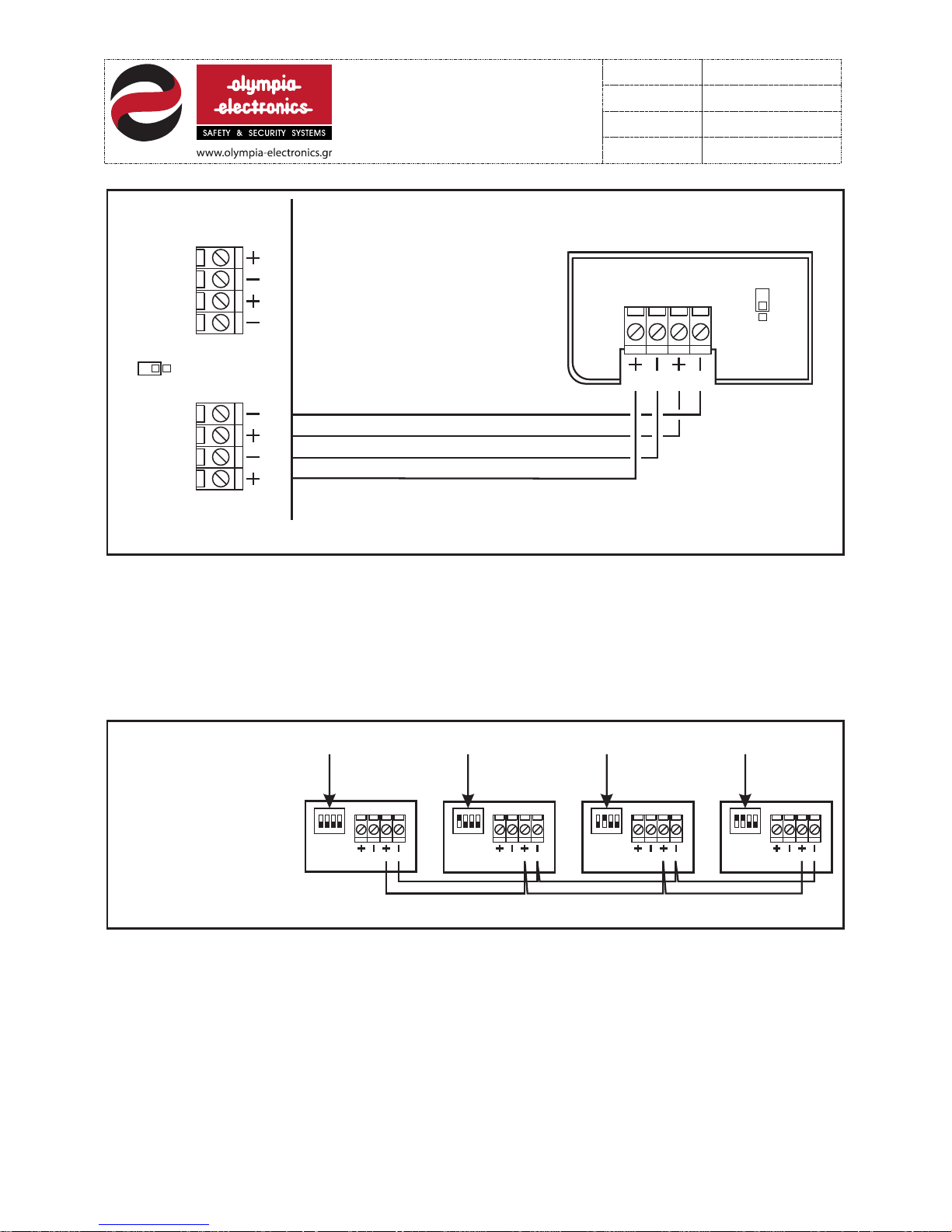
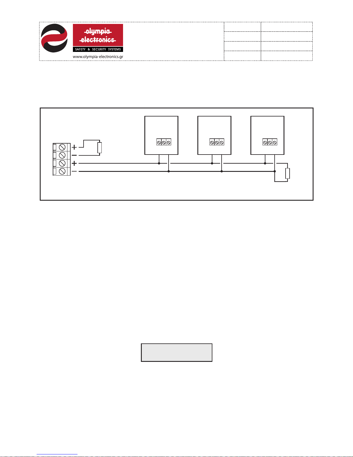
These de vic es are connected with 4 cables as shown in figure 1. The maximum cable length
must not exceed 500 metres.
The below figure shows the connection between BS-116 and BS-114. The same connection
is with BS-116 and BS-115, BS-117, BS-118.
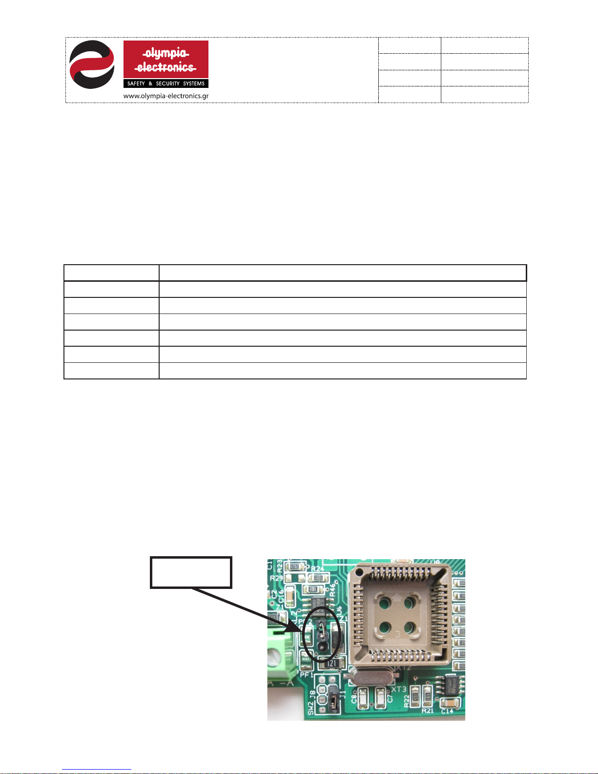
To activate the terminal resistor 120Ohm the J6 jumper must be connected to both pins
inside the PCB.
All the above devices are powered by the fire alarm panel BS-116.
3 fr om 21
9211160 00
Date
File
Code
Page
9211160 00 _0 9_ 01 6
13/03/2013
Jumper
J6
Page 4
4 fr om 21
9211160 00
Date
File
Code
Page
BS-116 conn ection
ATTENTION!!
ONLY 4 PANELS BS-116 CAN
BE CONNECTED IN ONE
INSTALLATIO N. To connect
the panels use ONLY the +A
and -A te rm in al s. D ON ’T U SE t he
+ and - terminals.
BS-116
pane l
BS-116
pane l
BS-116
pane l
BS-116
pane l
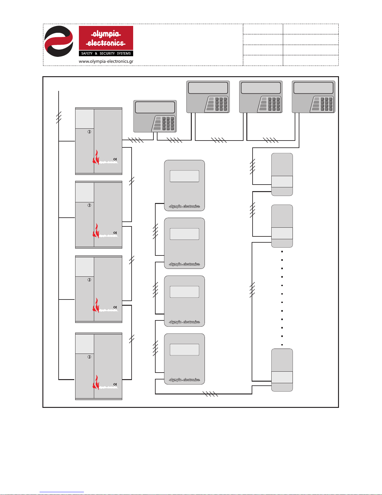
The maximum possible configuration consists of one BS-114 control keyboard, four BS-116
panels , three BS-115 repeaters, four BS-117 rel ay devices and eight BS-118 extinguishing
devices. Each device has it’s own address number. The connection between all of these
devices is shown in figure 2. Each panel can also accept a BS-620 megaphone driving
device.
Any configuration between the minimum and maximum described is possible. In this way a
fire detection panel with the required capabilities can be configured.
Figu re 1 C onnection of a BS -11 4 control keybo ar d with a BS-116 pa ne l
BS-11 4
Prog ra mming and
cont ro l keyboard
BS-11 6
Fire d et ection panel
-Connection between panels.
The make a network between pan only the +A, -A must be connected. Below picture shows
the connection between panels.
Attention!!! To give an address to each panel use the dip-switches as shown in the
following diagram (Address 1,2,3 and 4).
A
A
A
A
A
A
1 2 3 4 1 2 3 4 1 2 3 4 1 2 3 4
A
A
Address 1 Address 2 A ddress 3 Address 4
9211160 00 _0 9_ 01 6
13/03/2013
A
A
A
A
Siren 1 Siren 2
JP 1
J 6
Page 5
5 fr om 21
9211160 00
Date
File
Code
Page
No 4
Repeater
BS-115
No 1
No 2
No 3
No 4
Nο 2
No 1
No 2
No 3
BS- 116
ΨΗΦΙΑΚΟ Σ ΠΙΝΑΚ ΑΣ
ΠΥΡΑΝΙΧ ΝΕΥΣΗ Σ
16 ΕΩΣ 64 ΖΩ ΝΩΝ
Repe ater
BS-115
No 2
Repeater
BS-115
No 3
BS- 116
ΨΗΦΙΑΚΟ Σ ΠΙΝΑΚ ΑΣ
ΠΥΡΑΝΙΧ ΝΕΥΣΗ Σ
16 ΕΩΣ 64 ΖΩ ΝΩΝ
BS- 116
ΨΗΦΙΑΚΟ Σ ΠΙΝΑΚ ΑΣ
ΠΥΡΑΝΙΧ ΝΕΥΣΗ Σ
16 ΕΩΣ 64 ΖΩ ΝΩΝ
BS- 116
ΨΗΦΙΑΚΟ Σ ΠΙΝΑΚ ΑΣ
ΠΥΡΑΝΙΧ ΝΕΥΣΗ Σ
16 ΕΩΣ 64 ΖΩ ΝΩΝ
BS-118
fire
exti nguis hing
devi ce
No 8
Figu re 2
BS-118
fire
exti nguis hing
devi ce
No 1
Control
keyb oard
BS-114
Pane l
BS-116
230V AC
BS-117
16 rel ay devi ce
No 1
9211160 00 _0 9_ 01 6
13/03/2013
Page 6
4. Connections
All connections to the panel must be made before connecting the battery and the
mains power supply.
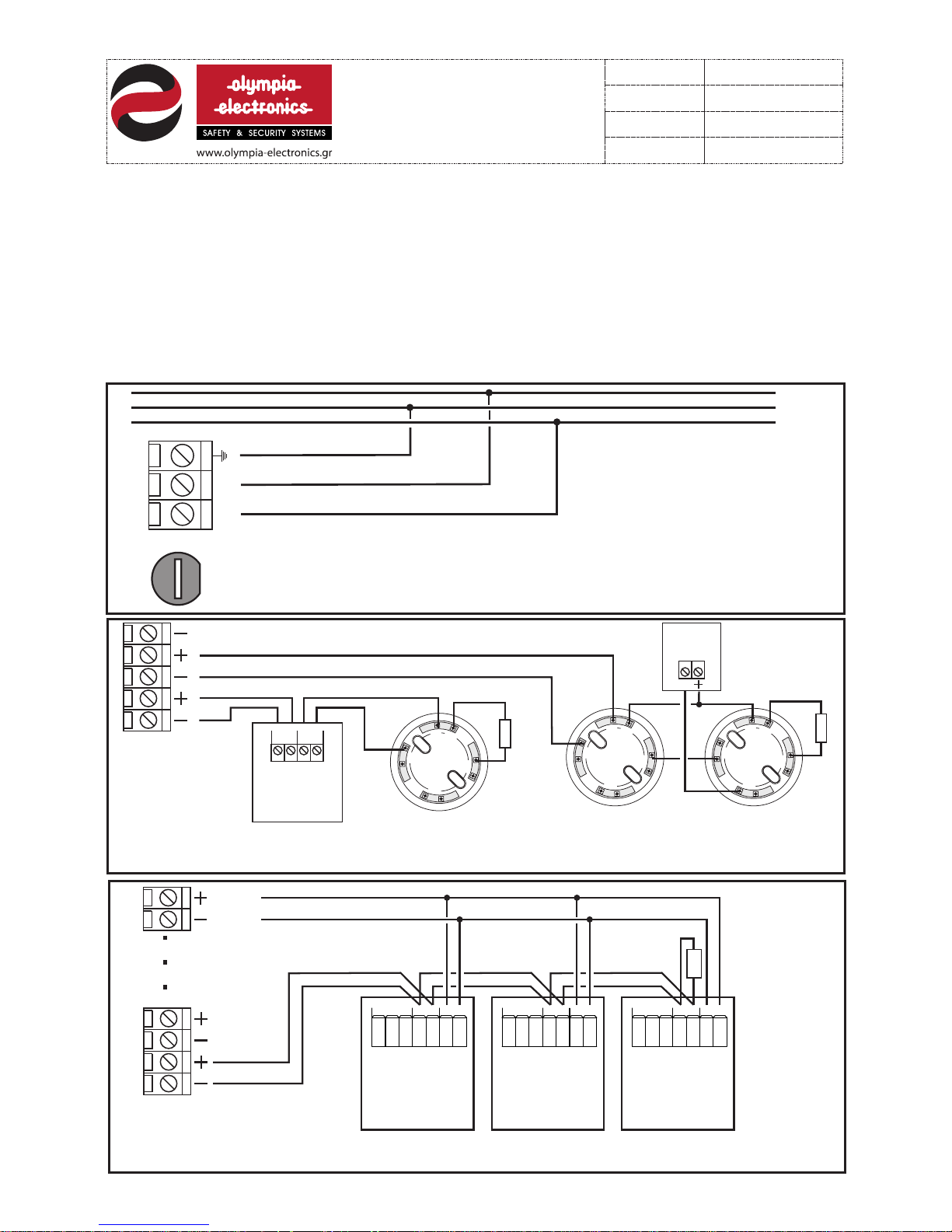
Each panel has terminal blocks for connecting 16 zones of detectors, break-glass call points
or o ther input devices. Each zone terminal block has a pre-fitted terminal resistor (5K6). This
resistor is removed and placed on the last device of the zone or it is left in it’s place if the
zone is not used.
The connections for all 16 zones are identical. What it show in figures 4 and 5 for zone 1 is
also valid for all the other zones.
1
2
3
5
4
Figu re 4 . Connecting 1 ma nu al call point BS- 536 and 1 detecto r ba se on zone 1and con necting 2 bases o f
dete ct ors on zone 2. One de te ctor also has a BS- 572 remote LED in di cator connect ed to it.
Det ector
bas e
Det ector
bas e
5Κ6
I
N
IN
O
U
T
O
U
T
R
I
N
IN
O
U
T
O
U
T
R
Remote
LED
BS-572
R
Termi nal
res istor
Det ector
bas e
I
N
I
N
O
U
T
O
U
T
R
Manual call
point
BS-536
OUT IN
5Κ6
Termi nal
res itor
FUSE
5x20 3A
L N
L
N
230V
~
Figu re 3. Con nection d iagram with the ma ins voltage .
ΖΟΝΕ 1
ΖΟΝΕ 2
GND
6 fr om 21
9211160 00
Date
File
Code
Page
5Κ6
1
2
3
4
24 Vdc
monitor
ZON E
10- 30V
NCNO CZON E
10- 30V
NCNO CZON E
10- 30V
NCNO C
Figu re 5 . Connecting 3 ga s de tectors BS-68 5 or BS-686. Besi de s connecting th es e detectors t o th e
zone w e mu st also power the m fr om the 24V dc monit or output.
Terminal
resistor
Gas
detector
BS-675
Gas
detector
BS-675
Gas
detector
BS-675
9211160 00 _0 9_ 01 6
13/03/2013
Page 7
Besides the terminal blocks mentioned the panel also has the following output:
24V uninterruptible : A 24Vdc uninterruptible power output that does not break in the event
of a panel reset. It can be used to power electromagnetic door latches.
Relay ALARM : A voltage free relay contact that is activated when a zone on the panel
issues an alarm.
Relay FAULT : A voltage free relay contact that is activated when the panel issues an error
or a fault.
The panel also has 2 cables for connecting the battery. The cable with the red connector is
for connecting the positive (+) terminal of the battery and the cable with the black connector
is for connecting the negative (-) terminal of the battery.
5. Starting configuration( Setup)
After all the connections to the panel are finished we can connect the battery and the 230V
AC power supply.
The first action that the BS-114 control keyboard must take is to recognize all the external
devices that are connected to the network. If the ENTER key is pressed then the display
shows:
Each panel has the required terminal blocks for connecting 2 siren circuits, bells or other
output devices that operate with 24Vdc. Each circuit can power devices with a maximum
consumption of 600mA. Each of these circuits has a pre-fitted terminal resistor (5K6). This
resistor is removed and placed on the last siren or it is left in it’s place if the circuit is not
used. The connections on both of these circui ts ar e ide ntical.
Figu re 6. Con necting 3 B S-531 sounders w ith beacon on the SI REN 1 output circu it.
When c onnec ting thes e devic e to the circ uit ensure that th e polarity is righ t.
SIREN 1
SIREN 2
5Κ6
5Κ6
Terminal
resistor
Terminal
resistor
BS-531
Sounder
with
beacon
GND
12V
24V
BS-531
Sounder
with
beacon
GND
12V
24V
BS-531
Sounder
with
beacon
GND
12V
24V
ENTER YOUR CODE
----
7 fr om 21
9211160 00
Date
File
Code
Page
9211160 00 _0 9_ 01 6
13/03/2013
Page 8
GENER A L S YSTEM
RESET 1 5
Enter the code ”9999” and the device will start the automatic recognition procedure and the
Display shows in sequence:
SEARC H I N G U N IT ΧΧ
SCI POI N T - > X X
Every time that a device is found it is shown on the display(e.g. Panel Νο 1) :
UNIT FO U N D
PANEL 1
When the detection procedure is finished the display shows in sequence :
GENER A L S YSTEM
RESET
HISTO RY FI L E H A S
DELET E D
SYSTE M R E A D Y
olymp i a e l e c tronics
The system has deleted the history record and is ready for testing and operation .
6. Operation procedures
There are 3 operations level on the panel.
Level 1.Level 1 operation can be done directly without the need of a code.
Leve 2. Level 2 operations are operations that are done by the user and need the user code
in order to be accessed.
Level 3. Level 3 operation are operations and setting that are done by the installation
technician and need the technician code (service code) in order to be accessed.
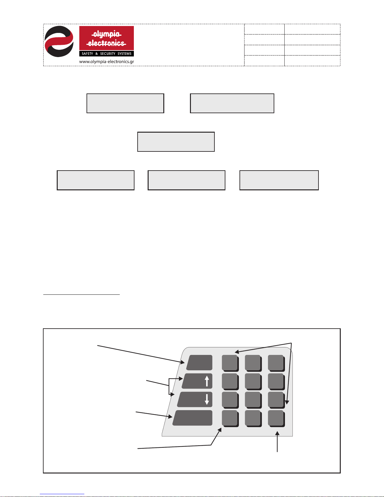
All operations are done using the BS-114 control and programming keyboard. The keys of
the devices operate the same on all operation levels.
6.1 Level 1 operations are all operations that are done by all personnel and d o not require
an access code. The keys that operate in thi s lev el ar e :
F1
HELP
ON - OFF
BUZZER
AL A R M
EVENTS
FAULT
EVENTS
ESC
ABCDE FGHIJ KL M N O
PQRST UV W X Y Z Ã Ä È Ë
ОРУЦШ Ù#()? % & ! + -
space
ENTER
21
5
4
87
0
3
6
9
yes no
To enter the hi story
record
Used for sc rolling up o r down
when in men us. Displa ying Alarm
or Fault ev ents.
Interna l buzzer act ivation
and deact ivation.
Cancell ing and operation or ret urning
to the prev ious menu.
Accepti ng and opera tion
or advanc ing to the nex t menu setti ng
Numeric
Keypad
8 fr om 21
9211160 00
Date
File
Code
Page
9211160 00 _0 9_ 01 6
13/03/2013
Page 9
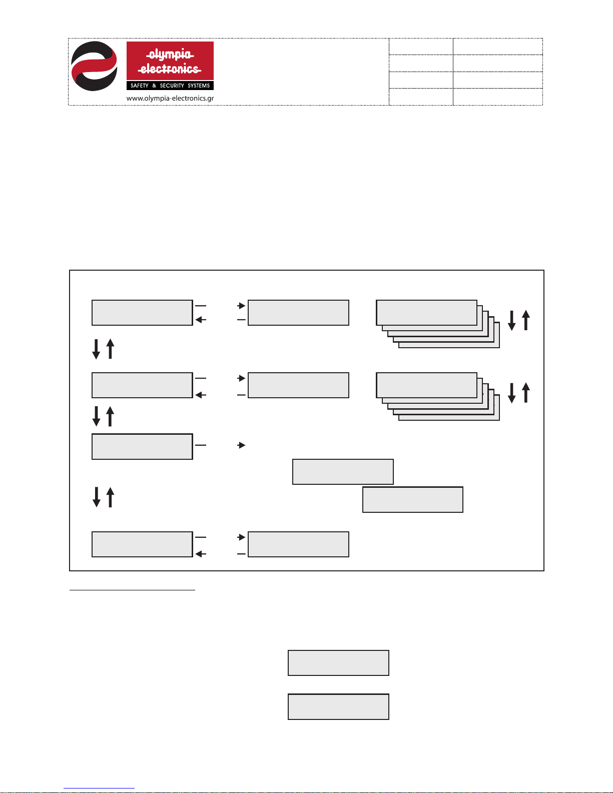
The function of Level 1 are:
Α. Activating or deactivating the internal buzzer. In the case of an alarm or a
fault condition the in ter nal buzzer will sound. To de act iva te the buzzer press the ‘ON-OFF
BUZZER HELP’ key. Press the key again to activate the buzzer.
Β. Display the history record. using the ‘F1’ key we can see the history record of
the system. In the same menu we can also see the version number of the software installed
in the device. The structure of th e men u and t he co rresponding indications is :
6.2 Level 2 oper ations are all operat ions that the us er can do. These op erations are found in a
menu. In order to access this menu the user must ent er a 4 digit access code. By default this
access code is set to <0000> , but can be chang ed with an other 4-digit code if it is required. In
order to en ter level 2 (u ser level) w e must follo w the follow ing proced ure.
Press the ‘ ENTER’ key . Th e Display sh ows:
If the‘0’ key is pressed 4 time then the
Display s hows:
Now we have e ntered the l evel 2 user me nu . The structure , operations and functions are:
ENT E R YOU R C ODE
--- -
SEL E CT->ENT E R
SYS T EM RES E T
SEL E CT->ENT E R
ALA R M HIST ORY
NOT E X IST
AL ARM EV E NTS
NOT E X IST
FAULT EVE N TS
×× ÓÕ Ì ÂÁÍ ALARM
ÆÙÍ Ç Ó ×
×× ÂÑ Á ×ÕÊÕÊËÙ ÌÁ
ÓÔÇ Æ Ù ÍÇ ×
×× ÂÑ Á ×ÕÊÕÊËÙ ÌÁ
ÓÔÇ Æ Ù ÍÇ ×
×× ÂÑ Á ×ÕÊÕÊËÙ ÌÁ
ÓÔÇ Æ Ù ÍÇ ×
ΧΧ ΒΡΑ Χ Υ ΚΥΚΛ Ω Μ Α
ΣΤΗ Ζ Ω ΝΗ Χ
ΧΧ S H ORT C I RCU I T
AT ZON E Χ
×× ÓÕ Ì ÂÁÍ ALARM
ÆÙÍ Ç Ó ×
×× ÓÕ Ì ÂÁÍ ALARM
ÆÙÍ Ç Ó ×
×× ÓÕ Ì ÂÁÍ ALARM
ÆÙÍ Ç Ó ×
ΧΧ ALARM E V ENT
ZON E Χ
SER VICE P H ONE
ΧΧΧ Χ ΧΧΧΧ Χ
SEL E CT->ENT E R
FAULT HIS TORY
SEL E CT->ENT E R
SER VICE P H ONE
CHE C K
ALL D ISPL AY
F1
ENTER
ESC
ESC
ESC
or
Or
ENTER
ENTER
ENTER
If no history record
is available
If a history record
is available
Sequential blinking of
the LEDs and then
oly m pia
ele c tron i cs
MAS T ER KEY B OARD
V1. 0 8 BS114 001 2
Exiting the menu
If no history record
is available
If a history record
is available
9 fr om 21
9211160 00
Date
File
Code
Page
9211160 00 _0 9_ 01 6
13/03/2013
Page 10
SEL E CT->ENT E R
SYS T EM RES E T
GEN E RAL SY STEM
RES E T 15
SEL E CT->ENT E R
EVAC U AT E
SEL E CT->ENT E R
SIR E N SILE N CE
ALA R M->S I LENC E D
ZON E Χ
SEL E CT->ENT E R
DIS A BLE ZO N ES *
DIS A BLE
ZON E S OF PANEL 1
ENA B LE
ZON E S OF PANEL 1
DIS A BLE
ZON E 0 7
ENA B LE
ZON E 0 7
xxx x xxxx x xxxx x x x
123 4 5678 9 0123 4 5 6
123 4 5678 9 0123 4 5 6
x -
123 4 5678 9 0123 4 5 6
123 4 5678 9 0123 4 5 6
SEL E CT->ENT E R
ENA B LE ZON E S *
<0000>
ENTER
ESC
ESC
ENTER
ENTER
ENTER
ENTER
ENTER
ENTER
ENTER
ENTER
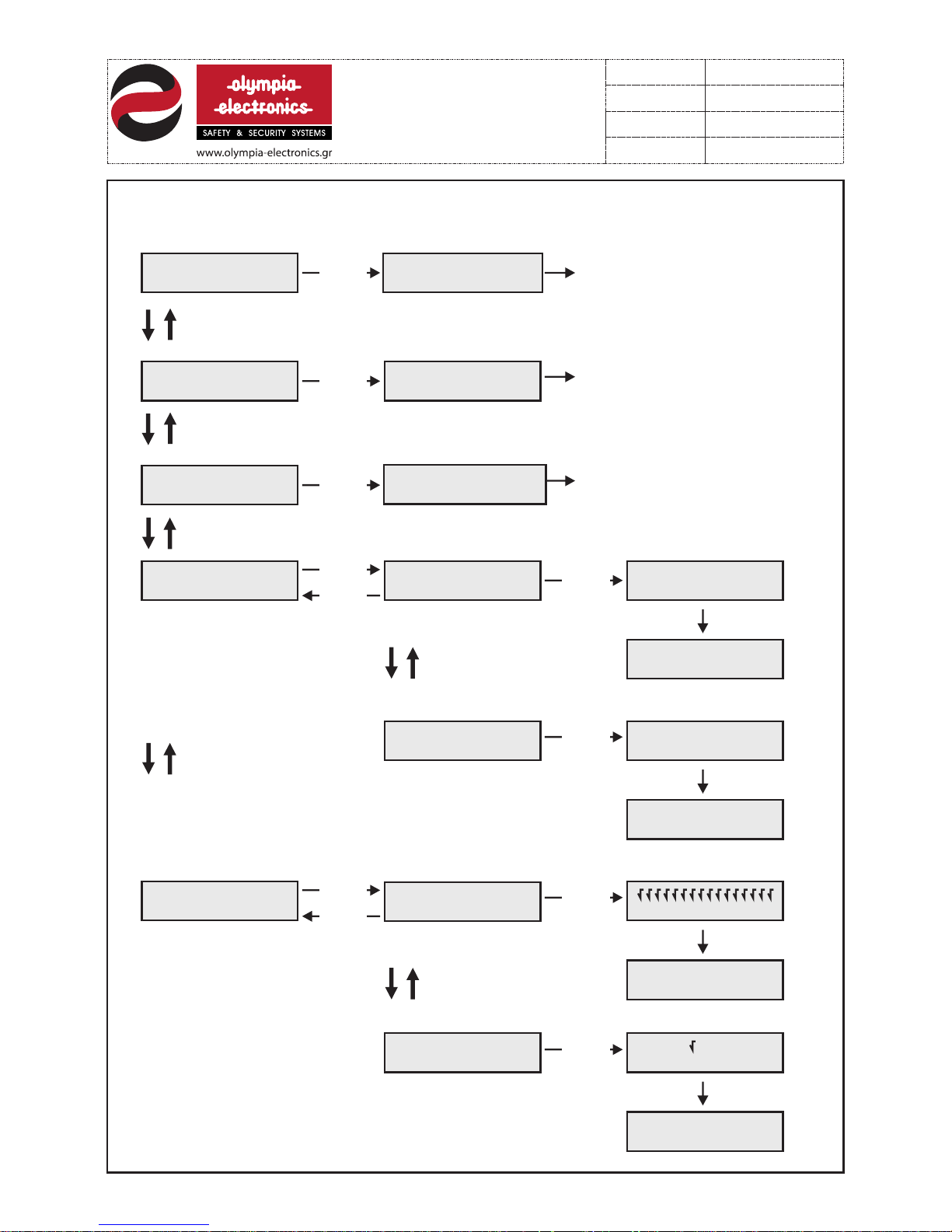
The detectors are reset, the LEDs are
tuned off, the sirens are silenced and
the relays are deactivated. After 15sec.
The panel enters normal operation.
A manual alarm is issued. The sirens are
sounded and the ALARM relays
are activated.
The sirens are deactivated. This setting
is only available only if an alarm condition
has occurred.
GEN E RAL SY STEM
RES E T
GEN E RAL SY STEM
RES E T 15
GEN E RAL SY STEM
RES E T
GEN E RAL SY STEM
RES E T 15
1 AL ARM
EVAC . F ROM KEY B .
10 f ro m 21
9211160 00
Date
File
Code
Page
9211160 00 _0 9_ 01 6
13/03/2013
Page 11
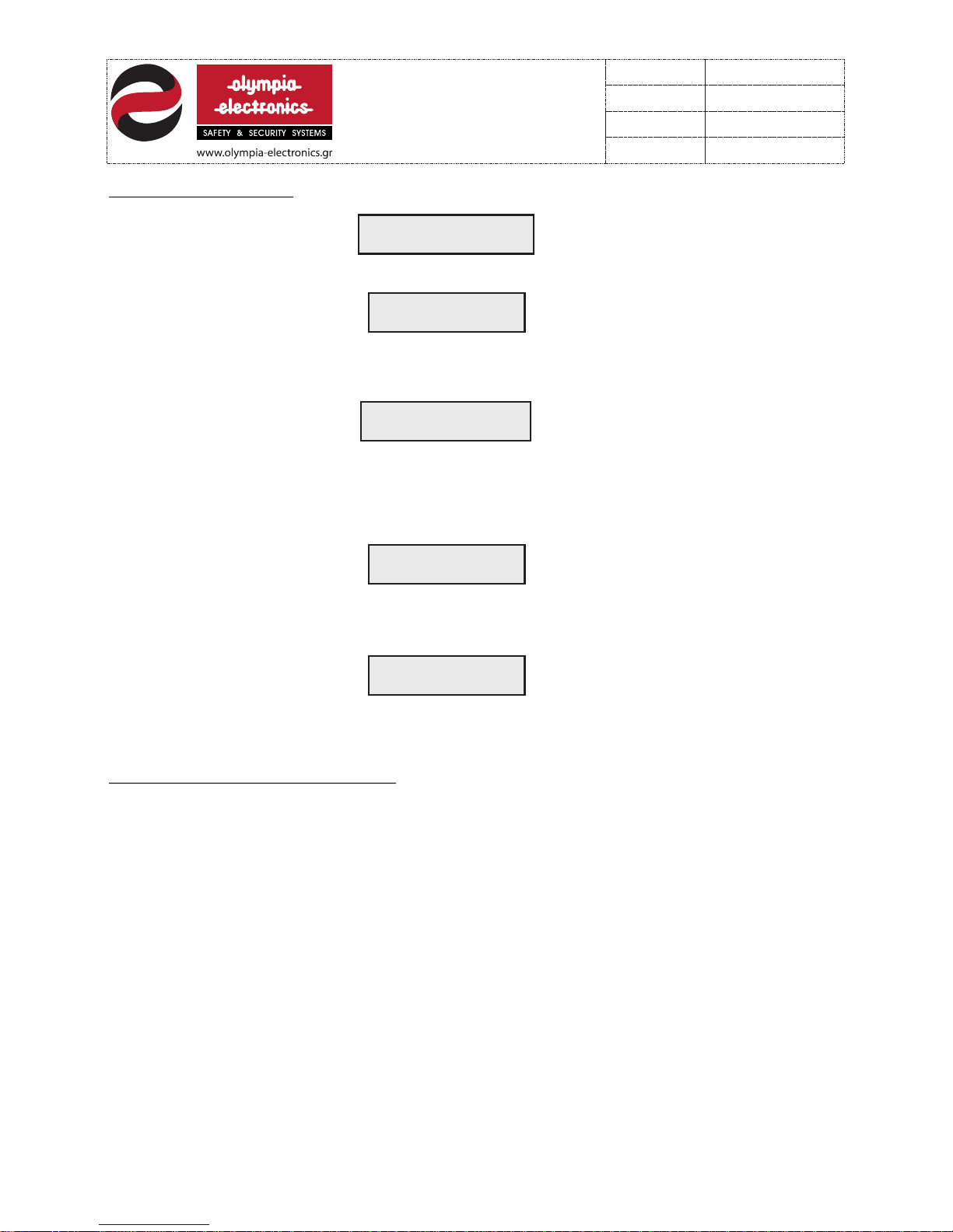
Sys t em Rea d y
oly m pia el e ctro n i cs
1 FAULT
AT PANEL 1
1 DIS C ONNE C TED B
AT PANEL 1
6.3 User instructions. In quiescent state the panel shows :
If the panel detects an error (e.g. Disconnection of the battery) the Display shows :
Simultaneously the internal buzzer sounds, the LED BATTERY lights and the FAULT relay is
activated. To deactivate the buzzer press the ‘ON -OFF BUZZER’ key. More information
concerning the problem can be obtained by pressing the ‘FAULT EVENTS’ key. In this case
the Display shows:
If mo re than 1 errors oc cur e then the Display sho ws the last error and the LIST LED lights to
indicate multiple errors. For more information press the ‘FAULT EVENTS’ key. After
correcting all errors we must RESET the system. Press the ‘ENTER’ key, enter the 4 di git
code, select‘SYSTEM RESET’ from the menu and press ‘ENTER’. The Display shows:
GEN E RAL SY STEM
RES E T
And after 15 sec the system enters normal operation mode.
If an alarm occurs on a zone (e.g. zone 8) the Display shows:
1 AL ARM
ΖON E 8
Simultaneously the internal buzzer sounds, the ALARM LED is activated and the ALARM
relay is energized.
Τo silence the buzzer and the sirens press the ‘ON-OFF BUZZER’.
To silence οnly the sirens press the ‘’ENTER’’ key and enter the user code.
|In order to RESET the system when the sirens are silenced press the ‘’ENTER’’ key, enter
the user code and select the appropriate option from the user menu.
11 from 21
9211160 00
Date
File
Code
Page
9211160 00 _0 9_ 01 6
13/03/2013
Page 12
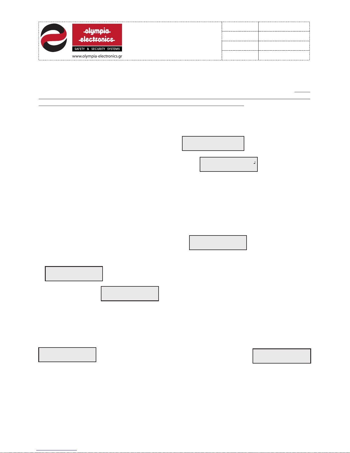
7. Programming - tests - information
:
Press the ‘ENTER’ button. The Display shows:
Then press the‘1’ key four times: The Display shows:
And we have entered in the technician menu.
After this we can conduct a full systems check, we can modify the configuration of the
system, we can see the various voltages in different stages of the system, we can also
activate or deactivate the various options. The deletion of the history record and the
modification of the user and technician codes can also be done in this level of operation.
Level 3 operation are operation the change the default factory settings of the system. For a
simple fire detection installation without any special requirement, there is no need for
any changes and the system can operate with the factory settings. It is mandatory to enter
this level only if th e installation requires special operations or settings.
In order to enter level 3 programming mode the technician code(service code) is required. This
is preset to <1111> but can be changed to any other 4-digit code. In order to access level 3
operations follow the procedure described bellow
ENT E R YOU R C ODE
--- -
SEL E CT->ENT E R
SYS T EM CHE C K *
SEL E CT->ENT E R
TES T *
TES T M ODE
WALK TE S T
ACT I VAT E 60:0 0
ZON E O NE BY ON E
When the system is in this state it can be
activated by an alarm in any zone. It activates the
sirens for 2 seco nds and then deactivates them
automatically.
Sequentially the technician can test the required zo nes by activating a
detector or call point. To exit this mode press the‘ESC’ key. This mode will
also be exited when the time shown on the Display has elapsed.
RES E T
ZON E S OF PANEL 1
setting ‘2=RESET’ starts to blink. Pressing the ‘ 1’ key reactivates all the
zones.
PANE L Z ONES 1
1=A C TIVE 2 = RESE T
When ‘ENTER’ is pressed the Display shows:
The setting ‘1=ACTIVE’ blinks.
In this state the technician can conduct a full systems check . When the
‘ENTER’ key is pressed the Display shows:
7.1 Tests
The first selection of the technician menu is If we press the
‘ENTER’
12 f ro m 21
9211160 00
Date
File
Code
Page
9211160 00 _0 9_ 01 6
13/03/2013
Page 13
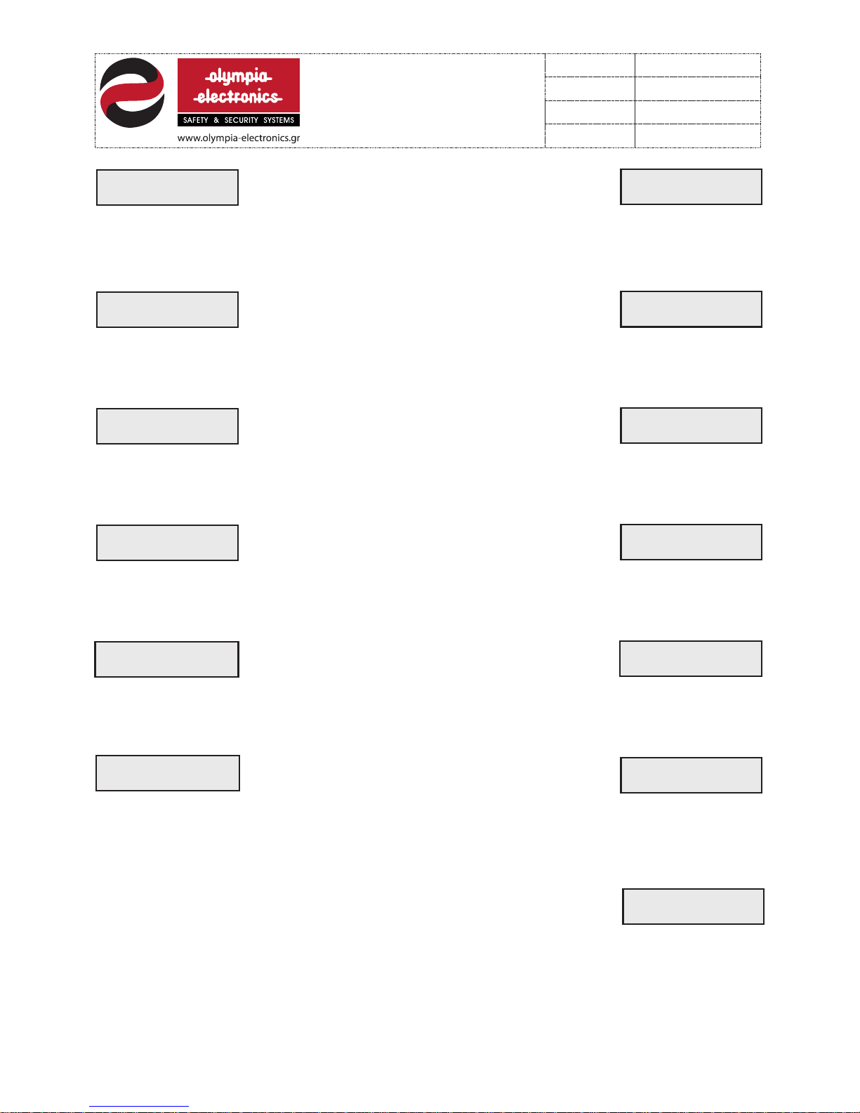
RES E T
ZON E 0 1
The setting ‘1=ACTIVE’ blinks. If the ’2’ key is pressed then the selected
zone is reset and the setting ‘2=RESET’ starts to blink. Pressing ‘1’ again
will reactivate the zone.
ZON E 0 1
1=A C TIVE 2 = RESE T
With the numeric keypad we select the required
zone and after pressing ‘ENTER’ we see :
TES T M ODE
ALA R M RELAY 1
The setting ‘2=DEACTIVE’ blinks. If the ‘1’ key is pressed then the relay is
activated and the setting ‘1=ACTIVE’ sta rts to blink. To deactivate the
relay press the ‘ 2’ key.
ALA R M RELAY 1
1=O N 2 =OFF
Select the ALARM relay on the required panel and
press ‘ENTER’. The Display shows:
TES T M ODE
FAULT REL AY 1
The setting ‘2=DEACTIVE ’ bli nks . If the ‘1’ key is pressed then the relay
is activated a nd the setting ‘1=ACTIVE’ starts to blink. To deactivate the
relay press the ‘2’ key.
FAULT REL AY 1
1= ON 2 = OFF
Select the FAULT rel ay on the required panel and
press ‘ENTER’. The Display shows:
TES T M ODE
SIR E N 1
The setting ‘2=DEACTIVE’ blinks. If the ‘1’ key is pressed then the output is
activated and the setting‘1=ACTIVE’ starts to blink. To deactivate the
output press the ‘2’ key.
SIR E N 1
1=O N 2 =OFF
Select the required siren output and press ‘ENTER’.
The Display shows:
TES T M ODE
24V-M O N ->PANE L 1
The setting blinks . If the ‘2’ key is pre ssed then the output is
deactivated and the setting ‘2=DEACTIVATE’ starts to blink. To reactivate
the output press the ‘1’ key.
‘1=ACTIVE’
24V-M O N ->PANE L 1
1=O N 2 =OFF
Select the output on the required panel and press
‘ENTER’ the Display shows:
The setting bli nks . If the ‘1’ key is pressed then the relay is
activated and the setting ‘1=ACTIVE’ starts to blink. In order to deactivate
the relay press the ‘2’ key. If a BS-117 relay module is not connected to the
‘2=DEACTIVE’
REM O TE REL AY 01
1=O N 2 =OFF
Select the required zone relay and press
‘ENTER’. The Display shows:
UNI T I S
NOT C O NNEC T ED
system then this operation is not available and the
system displays the message:
TES T M ODE
REL AY (1/6 4 ) 01
13 f ro m 21
9211160 00
Date
File
Code
Page
9211160 00 _0 9_ 01 6
13/03/2013
Page 14
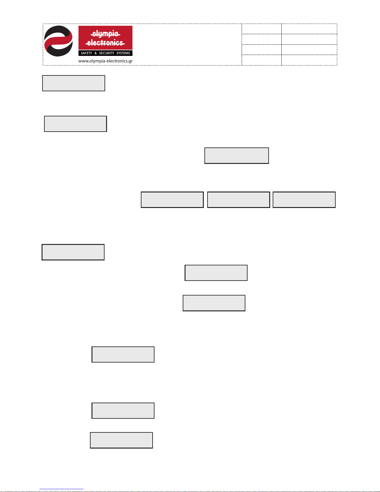
TES T MODE
HAR D WA R E CHECK
When ‘ENTER’ is pressed the system will start a check that i ncl ude s a
HARDWARE check of the panel, the zones, the sir ens , and the ‘24Vmonitored’ out put s. In every check it issues a message stating the right
or wrong configuration of each input or output.
TES T MODE
COM M UNIC AT I ONS
External devices communication test.
7.2 Programming
The second selection in the technician menu is If we press ‘ENTER’
we enter the sytem configuration submenu.
With t his submenu we can change the mode of operation of the system outputs. Before
entrance to the submenu is admitted the system warns us and ask for confirmation . The
display shows:
SEL E CT->ENT E R
CON F IGUR AT I ON *
!!C A UTIO N !!
SYS T EM SET T INGS
MAYB E
CHA N GED
ARE Y OU SUR E ?
ENT E R=YE S
If ‘EN TER’ is pressed we enter the system configuration submenu(programming).The
selections that are available are:
CON F IGUR E
ALA R M RELAY 1
ACT I VAT E MODE *
GEN E RAL A L A RM
Select the ALARM relay of the required panel and press
‘ENTER’. The default activation method is shown:
If we want to change the activation method then we must press the ‘FAULT EVENTS’
key. The display shows:
Press ‘ENTER’ and using the‘FAULT EVENTS’ key select the required
activation method. The selections are the following:
ACT I VAT E FROM
GEN E RAL ALA R M
1.
The relay is activated when any zone issues an ALARM. By
pressing the ‘ENTER’ key we can change the time that the
relay will be activated between 1 to 255 seconds
(the time 000 means continious operatio n) or by pressing
the ‘FAULT EVENTS key we can set the delay before the
ACT I VAT E FROM
FAULT EV E NTS
2.
The relay is activated when an error occurs. We can also
adjust the operation time and the time to operate delay
using the above mentioned method.
CHA N GE MOD E O F
ACT I VAT ION *
relay will be activated between 1 to 255 seconds ( the selection 000 means no
delay).
ACT I VAT E FROM
1-1 6 Z ONES ( O R)
3.
It is activated when one or more preselected zones issue
an alarm. If this selection is made then by pressing
‘ENTER’ we must select the required zones on the
next menu.
14 f ro m 21
9211160 00
Date
File
Code
Page
9211160 00 _0 9_ 01 6
13/03/2013
Page 15
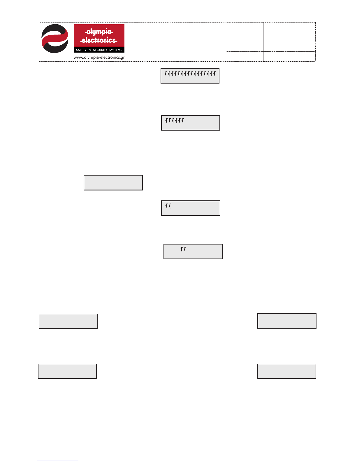
The display shows:
123 4 5678 9 0123 4 5 6
The cursor blinks over the ‘1’ digit . If we want the relay to be activated by lets say
zones 1,2,3,4,5 and 6 press the’1’ key (yes) 6 times. The cursor is moved 6
positions to the right and is positioned over the ‘7’. Press the ‘2’ key (no) 10 times
and the display will show:
123 4 5678 9 0123 4 5 6
Pressing ‘ENTER’ will activate the selection. The relay will only be activated when
one of the preselected zones (ticked) issues an alarm. We can also adjust the
operation time and the time to operate delay as d escribed earlier.
ACT I VAT E FROM
TWO Z O NES (A N D)
4.
The relay is activated when 2 preselected zones issue an
alarm .If this method of activation is selected the by
pressing ‘ENTER’ we must select the desired zones on
the next menu.
The Display shows:
123 4 5678 9 0123 4 5 6
The cursor blinks over the ‘1’. If we want the relay for example to be activated
by zones 5 and 6 the press the ‘2’ key for 4 times. Th e curcors shifts 4 places to the
right and is positioned over the ‘5’. Press the ‘1’ key (yes) 2 times and the display
shows:
123 4 5678 9 0123 4 5 6
By pressing ‘ENTER’ the setting is activated . Th e relay will be activated only if both
zones 5 and 6 issue and alarm. We can also adjust the operation time and the time
to operate delay as described earlier.
The second device that can be programmed is the FAULT relay.
We select it by pressing ‘ENTER’.
CON F IGUR E
FAULT RE L AY 1
ACT I VAT E FROM
GEN E RAL FAU LT
After ‘ENTER’ is pressed the activation method is
shown.(default=GENERALl FAULT) If we want to
alter the activation method we must follow exactly the same procedure as
described earlier for the programming of the ALARM relay. The options and
settings are identical.
CON F IGUR E
SIR E N 1
ACT I VAT E FROM
GEN E RAL A L A RM
We can also program the s iren output. We can
select using the ‘ FAULT EVENTS’ key
Select the required output using the numeric keypad and by pressing ‘ENTER’ we can see it’s
activation method (default=general ALARM). If we want to change the activation method press
the ’FAULT EVENTS’ key and ‘ENTER’. The options available are. “ACTIVATED BY GENERAL
ALARM” and “AC TIVATED BY ZONES(OR)”. The functions of the setting are the same as
described earlier for the ALARM relay. With the option “DURATION” we can select if the output
will have a permanent or an interruptible operation. The settings are the following:
0= permanent operation
1 = interruptible operation with 3 seconds ΟΝ - 5 seconds OFF
15 f ro m 21
9211160 00
Date
File
Code
Page
9211160 00 _0 9_ 01 6
13/03/2013
Page 16
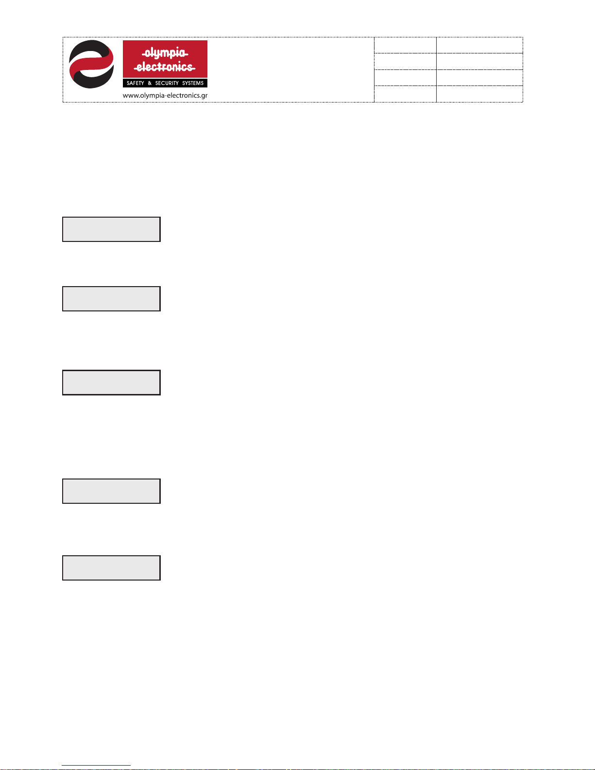
Programming zone relays. If a BS-117 relay module is connected we can select.
CON F IGUR E
REL AY ( 1/64 ) 0 1
Using the numeric keypad and pressing enter we can select the relay
that will be programmed.
1 = interruptible operation with 3 seconds ΟΝ - 5 seconds OFF.
2 = interruptible operation with 10 seconds ΟΝ - 5 seco nds OFF.
3 = interruptible operation with 5 seconds ΟΝ - 15 seconds OFF.
4 = interruptible operation with 1 seconds ΟΝ - 1 seconds OFF.
From the delay option we can adjust the time that the selected outp ut will be activated
after the alarm is issued. This delay can be between 1 and 255 seconds.
Programming the start to ext inguish delay. If a B S-118 is i nstalled then th is option is used
CON F IGUR E
F-E X R ELAY 1
for activation delay of the Delay relay in each fire extinguishing
module. Using the numeric keypad and the ‘ENTER ‘ key we select the fire
extinguishing module that we want to adjust the delay.
(1 - 120 seconds).
Programming the repeater panel functions.
CON F IGUR E
REP E ATER 1
If a BS-115 is installed then using this selection we can adjust the
permissible functions that will be done with it. Using the keyboard and
‘ENTER’ we select the repeater panel that we want to adjust if it is
going to have the capability of evacuation, the capability of resetting the
system or the capability of silencing the sirens.
Programming the internal buzzer. With this option we can adjust the sound mode of the intern al
buzzer (selecting 0 or 1).
CON F IGUR E
BUZ Z ER 1
Resetting to default fact ory setting. If the ‘ ENTER ’ key is pressed and after the system warns
and asks for confirmation it reset all settings to factory defaults and detects all the
devices that are connected on the communication line.
DEFAU LT PA RAMs
SET T INGS
Programming the internal buzzer. With this option we can adjust the sound mode of the intern al
buzzer (selecting 0 or 1).
16 f ro m 21
9211160 00
Date
File
Code
Page
9211160 00 _0 9_ 01 6
13/03/2013
Page 17
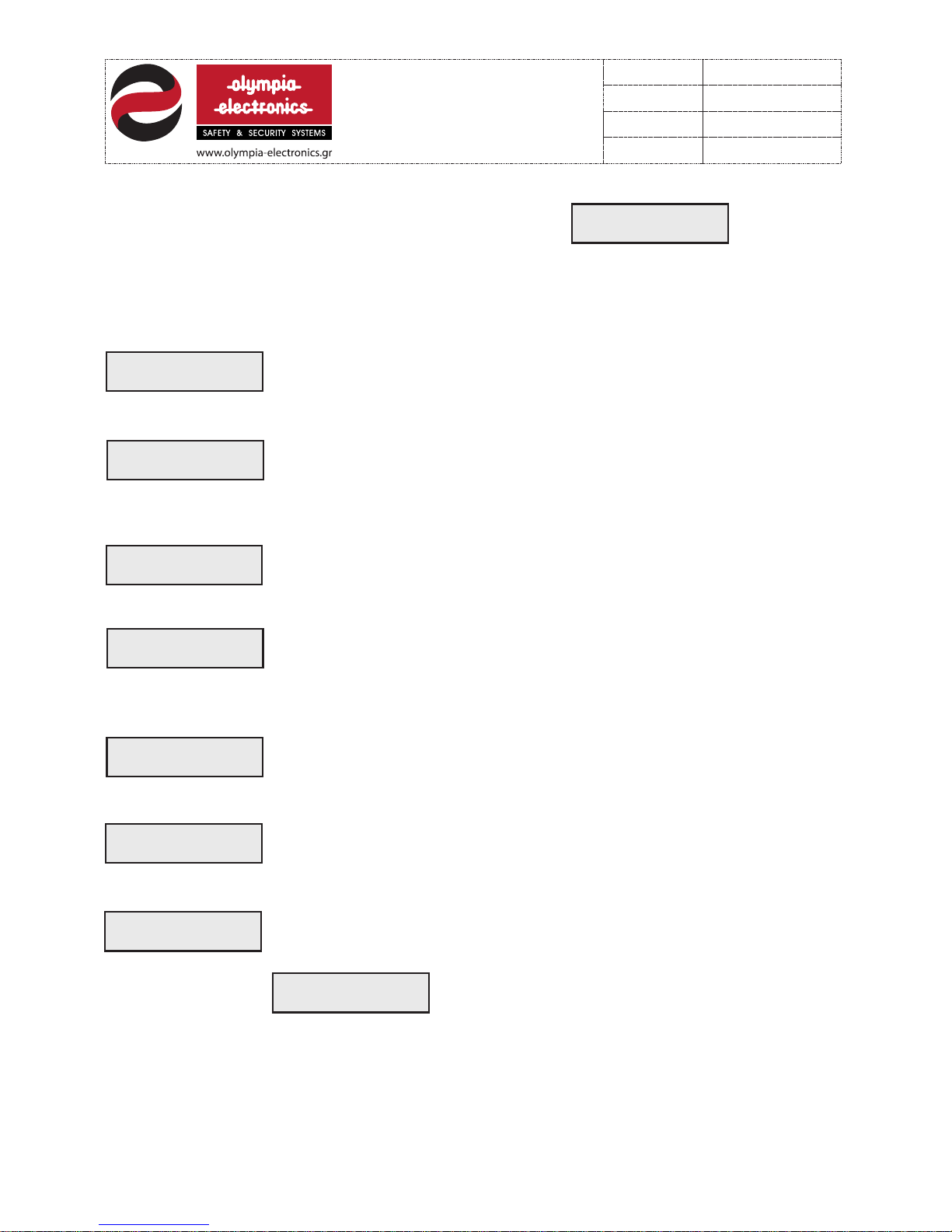
7.3 Information
The third option available in the technicians menu is
If the ‘ENTER’ key is pressed we en ter the systems information submenu. Through this
submenu we can observe the voltages on the various stages of the system and information
concerning connected devices. The options of the submenu are:
SEL E CT->ENT E R
INF O RMATIO N
INF O RMATIO N
ZON E 0 1
Select, using the numeric keypad and the key ‘ENTER’, the required zone
to view its voltage. Acceptable readings are 23.5V to 25.0V (depending on
the number of detectors connected.
INF O RMATIO N
SIR E N 01
Select ,using the numeric keypad and the ‘ENTER’ key, the required siren
output to view its voltage. Acceptable readings in quiescent state are 0.5V
to 3.3V (depending on the number of sirens connected).
INF O RMATIO N
MAI N S AT PAN EL 1
Select, using the numeric keypad and the ‘ENT ER’ key, the required panel
to view its mains operation voltage. Two readings are available, ‘GOOD’
or ‘LOW’.
INF O RMATIO N
BATT. O F PANEL 1
Select using the numeric keypad and the ‘ENTER’ key, the re qui red panel
in order to view its battery voltage. After a 24 charging cycle the
reading should be in the range of 13.5 to 13.8V.
INF O RMATIO N
VCC AT PANE L 1
Select, using the numeric keypad and the ‘ENTER’ key the required panel
in order to view its power supply operation voltage. It should be in the
range of 26.5 to 28V.
INF O RMATIO N
24V-M O N ->PANE L 1
Select ,using numeric keypad and the ‘ENTER key, the desired panel in
order to view the voltage on the 24V monitored output. It should be
between 26.5 and 28V.
INF O RMATIO N
CON N ECTE D U NITS
If the ‘ENTER’ key is pressed the Display will show information for every
device that is connected to the network . For example the display will
show:
PANE L 1
V1. 0 6 BS116 00 1 2
This means that panel 1 has software version V1.06,
is the type BS - 116 and that the software
development date is the 12th month of the yea r
2000.
17 f ro m 21
9211160 00
Date
File
Code
Page
9211160 00 _0 9_ 01 6
13/03/2013
Page 18
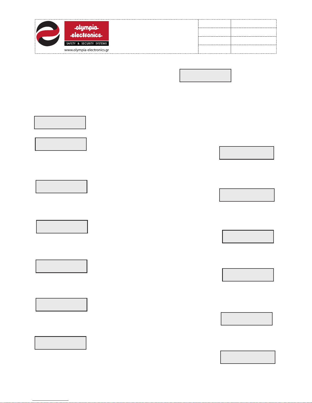
7.4 Deactivation
The fourth selection on the technicians menu is
If ‘ENTER’ is pressed then we enter the deactivation submenu of the system. Through
this menu we can deactivate the operation of the zones and the outputs of the system . The
available selections are:
SEL E CT->ENT E R
DIS A BLE IT E MS *
DIS A BLE
ALL SYST E M
If ‘ENTER’ is pressed then all individual devices of the system cease to
operate.
DIS A BLE
ZON E S OF PANEL 1
Using the keypad and pressing ‘ENTER’ we select the desired panel. The
Display shows:
xxx x xxxx x xxxx x x x
123 4 5678 9 0123 4 5 6
DIS A BLE
ZON E 0 1
With the numeric keypad and the ‘ENTER’ key we select the required
zone. The Display shows:
x
123 4 5678 9 0123 4 5 6
DIS A BLE
ALA R M RELAY 1
With the numeric keypad and th e ‘ENTER’ key we select the required
ALARM relay. The Display shows:
And the relay is deactivated.
ALA R M RELAY 1
IS DI S ABLE D
DIS A BLE
FAULT RE L AY 1
With the numeric keypad and the ‘ENTE R’ key select the r equ ire d FAULT
relay. The Display shows:
And the relay is deactivated.
FAULT RE L AY 1
IS DI S ABLE D
DIS A BLE
SIR E N 1
With the numeric keypad and the ‘ENTER’ key select the required SIREN
output. The Display shows:
And the siren output is deactivated.
SIR E N OUTP U T 1
IS DI S ABLE D
DIS A BLE
REL AY S OF UNIT 1
With the numeric keypad and the ‘ENTER’ key select the required BS-117
device. The Display shows:
If ‘ENTER’ is pressed again then all the relays belonging to the selected
BS-117 device are deactivated.
xxx x xxxx x xxxx x x x
123 4 5678 9 0123 4 5 6
18 f ro m 21
9211160 00
Date
File
Code
Page
9211160 00 _0 9_ 01 6
13/03/2013
Page 19
DIS A BLE
REL AY ( 1/64 ) 0 1
With the numeric keypad and the ‘ENTER’ key select a specific relay (e.g.
Relay 1) on the required BS-117 panel.
The Display shows.
x
123 4 5678 9 0123 4 5 6
If ‘ENTER’ is pressed again, the selected relay is deactivated.
7.5 Activation
The fifth selection on the technicians menu is
If ‘ENTER’ is pressed we enter the activatio n submenu of the system. Through this
submenu we can activate the zones and the outputs of the system. The available selections
of the submenu are.
SEL E CT->ENT E R
ENA B LE ITE M S *
ENA B LE
ALL SYST E M
If ‘ENTER’ is pressed then all devices that were previously deactivated
are now activated.
ENA B LE
ZON E S OF PANEL 1
With the numeric keypad and the ‘ENTER’ key select the required
panel. The Display shows:
ENA B LE
ZON E 0 1
With the numeric keypad and the ‘ENTER’ key select the req uired zone of
the panel. The Display shows:
All activated zones are marked with the ‘ ‘ symbol.
ENA B LE
ALA R M RELAY 1
With the numeric keypad and the ‘ENTER’ key select the required ALARM
relay. The Display shows:
And the relay is activated.
ALA R M RELAY 1
IS EN A BLED
ENA B LE
FAULT RE L AY 1
With the numeric keypad and the ‘ENTER’ key select the required FAULT
relay. The Display shows:
And the relay is activated.
FAULT RE L AY 1
IS EN A BLED
123 4 5678901 23456
123 4 56789 0 12345 6
19 f ro m 21
9211160 00
Date
File
Code
Page
9211160 00 _0 9_ 01 6
13/03/2013
Page 20
ENA B LE
SIR E N 1
With the numeric keypad and the ‘ENTER’ key select the required SIREN
output. The Display shows:
And the siren output is activated.
SIR E N OUTP U T 1
IS EN A BLED
ENA B LE
REL AY S OF UNIT 1
With the numeric keypad and the ‘ENTER’ key select the required BS-117
device. The Display shows:
If ‘ENTER’ is pressed then all the relays of the BS-117 are activated.
123 4 5678901 23456
ENA B LE
REL AY ( 1/64 ) 0 1
With the numeric keypad and the ‘ENTER’ key select a specific relay (e.g
relay1) of the selected BS-117 device. The Dis play s hows:
If ‘ENTER’ is pressed again then the chosen relay is activated.
123 4 5678901 23456
7.6 History record deletion
The sixth selection of the technicians menu is
If ‘ENTER’ is pressed then the history record of the system is deleted. All ALARM and
FAULT events are written in this record.
DEL E TE
HIS TORY F ILE
7.7 Automatic unit recognition
The seventh selection in the technicians menu is
If ‘ENTER’ is pressed the SETUP procedure described in section 5 commences.
AUT OMATIC
UNI T DETE C TION
7.8 Setting the user code.
The eight selection in the technicians menu is
If we press ‘ENTER’ the display shows :
Using the numeric keypad enter the required 4-digit code that will be used as a user
access code. The default user code set is “0000”.
SET
USE R C ODE
ENT E R YOU R C ODE
000 0
20 f ro m 21
9211160 00
Date
File
Code
Page
9211160 00 _0 9_ 01 6
13/03/2013
Page 21
7.9 Setting the service access code
The ninth selection in the technicians menu is
If ‘ENTER’ is pressed then the display shows:
Use the numeric key pad to enter a new 4-digit access code for the technician. The default
technician code is “1111”.
SET
SER VICE C O DE
ENT E R YOU R C ODE
1111
7.10 Setting the service telephone.
The tenth selection found in the technicians menu is
If ‘ENTER’ is pressed the display shows:
Use the numeric keypad to enter the technicians telephone number. This te lep hon e number
will show on the display after every Fault condition on the panel.
All the programming selection described are valid only after exiting the programming menu.
In some cases when we exit the programming menu the panel conducts an automatic
RESET.
If we try to program an option on a device that is not on the network the n the system issues
the following message on the display.
SET
SER VICE P H ONE
SER VICE P H ONE
UNI T I S
NOT C O NNEC T ED
220 - 240 VAC / 50-60 Hz 60VA
12V/7Ah lead-acid (Pb)
Stabilized power supply 13,8V/ 5OO mA
36 hours (without using the 24V output)
16 zones fully monitored of open and short circuit conditions
Two 24V circuits monitored for open and short circuit conditions
1 voltage-free ΑLARM RELAY contact, 1 voltage-free FAULT RELAY contact
o
0 to 50 C and 95% relative humidity
ABS ,Αluminium and Polycarbonate
300 x 430 x 90 mm / 4.2Kgr
IP 30
2 years
MAINS VOLTAGE
BATTERY TYPE
CHARGING CIRCUIT
DURATION
ZONE CIRCUIT
ALARM CIRCUITS
OUTPUTS
OPERATION RANGE
PRODUCED IN ACCORDANCE WITH
CONSTRUCTION MATERIAL
DIMENSIONS / WEIGHT
COVER PROTECTION
GUARANTEE
TECHNICAL CHARACTERISTICS
EN 54-2, EN 54-4
21 f ro m 21
9211160 00
Date
File
Code
Page
9211160 00 _0 9_ 01 6
13/03/2013
 Loading...