

Olympia POWER LIGHT, POWER LIGHT GR-21/H, POWER LIGHT GR-21, POWER LIGHT GR-29 Quick Start Manual
Page 1
High Quality European based Manufacturers
``POWER LIGHT`` SERIES FOR NON-MAINTAINED EMERGENCY LUMINAIRES
TECHNICAL CHARACTERISTICS
OPERATION VOLTAGE
MAXIMUM POWER CONSUMPTION
BATTERIES (Pb)
BATTERY PROTECTION
INDICATIONS - CONTROLS
CHARGING TIME
MINIMUM AUTONOMOUS DURATION
LIGHT SOURCE
EMERGENCY ILLUMINATION
DEGREES OF COVER PROTECTION
PRODUCED IN ACCORDANCE WITH
OPERATION TEMPERATURE RANGE
RELATIVE HUMIDITY
CONSTRUCTION MATERIALS
EXTERNAL DIMENSIONS
TYPICAL WEIGHT
GUARANTEE
GR-21 GR-29GR-21/Η
14 VA 24 VA
12 V/ 7Ah
90 m in 60 m in 3h
2x 20 W (h alog en) 2x 20 W (h alog en) 2x 55 W (h alog en)
58 0l m 16 20 lm 580 lm
EN 6 0598- 1, EN 60 598- 2-22 , ΕΝ 550 15, ΕΝ 6 1547 , ΕΝ 610 00-3 -2, ΕΝ 6 1000 -3-3
302 x 94 x 330 mm 302 x 94 x 330 mm
33 30 gr. 53 00 gr.
Thank you for purchasing this product of
Olympia Electronics. A European manufacturer.
GENERAL
These luminaires are used indoors (ta 40 C)
o
wh ere e merg ency ligh t is n eede d. Ea ch
luminaire must be permanently connected to
mains power supply. In normal operation the
power and the charge indicators light to show
that the batteries are in charging condition. In
case of a mains power supply failure the
power and the charge indicators turns off and
th e lu min air e wi ll l igh t th e sp ot l amp s
automatically in emergency mode. When the
mains power supply is restored the device
turns to normal operation.
INSTALLATION
To install the luminaire follow the installation
instructions οn page 2.
OPERATION
When the device is powered from the mains,
the charge and power indicators should light.
The charge indicator confirms the charging of
the batteries. If it does not light, probably, the
batteries are disconnected. If it does not light
and the batteries are connected, then contact
the technician. As long as the charge indicator
blinks, the batteries of the luminaire are
charging and in this period, any autonomy test
must be avoided. When the charging circle is
complete, the indicator lights continuously (it
can be used as an indication of a power
22 0- 240 V AC/ 50- 60 Hz
From overcharge and deep discharge
Power indicator, battery charge indicator, TEST button
0 to 4 0 C
Ba yb len d FR 30 10, t ra ns par en t po l yc ar bo nate
3 ye ar s (1 y ear fo r the la mps an d the ba tter y)
Up t o 95 %
325 x 120 x 380 mm
72 90 gr.
2x 12 V/7 Ah
24 h
IP 4 2
o
interruption). The batteries charging is done by
an 3 stages technological advanced procedure,
to ensure the appropriate and full charging of
the batteries.
The power indicator confirms the proper
connection to the mains. The TEST button, has
a dual use. If pressed instantlly while the device
is connected to the mains, the device simulates
the power interruption, by lighting the lamps for
3''. In this way, we can control the driver circuit
of the lamps and the lamps as indicated in
paragraph 3 in the text below .
Wh e n the volt a g e is inte r r u pted, with
corresponding pressings of the button, we can
choose the operation of 2,1 or no lamps, either to
increase the autonomy time or not to consume the
battery power unnecessarily. This option is
canceled when the network is restored.
ΑΤΤΕΝΤΙΟΝ!!!
1. Operations for installation, maintainance or
testing must be done by authorized personel
only.
2. The device must be connected to the mains
power supply thru a fuse dependent by the total
amount of the line’s power load.
3. It is sugested to check every month the
indication LED for battery charging, and by
pushing instantly the TEST button to check the
em e r g ency c i r q uit an d t he lam p s . If the
luminaire does not light contact the installer.
4. It is sugested to check every 6 months the
Page 1 from 2
923029000_23_023
Page 2
m i n i m u m a u t o n o n o u s d u r a t i o n b y
disconnecting the mains power supply. Count
the time that the
lamps light and in case of less time than the
minimum autonomous duration the batteries
must be replaced. If the measured time is
c o n s i d e r a b l y l e s s t h a n t h e m i n i m u m
autonomous duration contact the installer.
The replacement of the battery and the light
source must be done using parts of the same
type, by the manufacturer or by a competent
person.
5. In case of inactive use for a period greater
than 2 months, disconnect the battery by
pulling out the battery’s connector.
6. I s not allowed to discard batteries in to t i
co mmon tras h bin s, th ey mu st be
discarded only in battery recycling
points. Do not incinerate.
NOTE: LED= Light Emitting Diode
LABELING EXPLANATION:
X: Self contained
0: Non-maintained (*)
A: Including test device
*60: 1 hour duration
*90: 1,5 hour duration
180: 3 hour duration
(*) Non-Maintained operation: The luminaire
lights its illumination source, only in power
supply’s failure.
Maintained operation: The luminaire lights its
illumination source, when it is powered by the
mains power supply or not.
Battery replacement.
It can be done only by a competent person and
after the mains interruption.
1. Follow t h e s t e p 2 o f t h e i n s t allation
procedure.
2. Disconnect the cables and remove the old
battery.
3. Connect the new battery with the same type
(step 3 of the installation procedure) and place it
in the position of the old one.
4. Follow the step 5 of the installation procedure
and power the device..
1
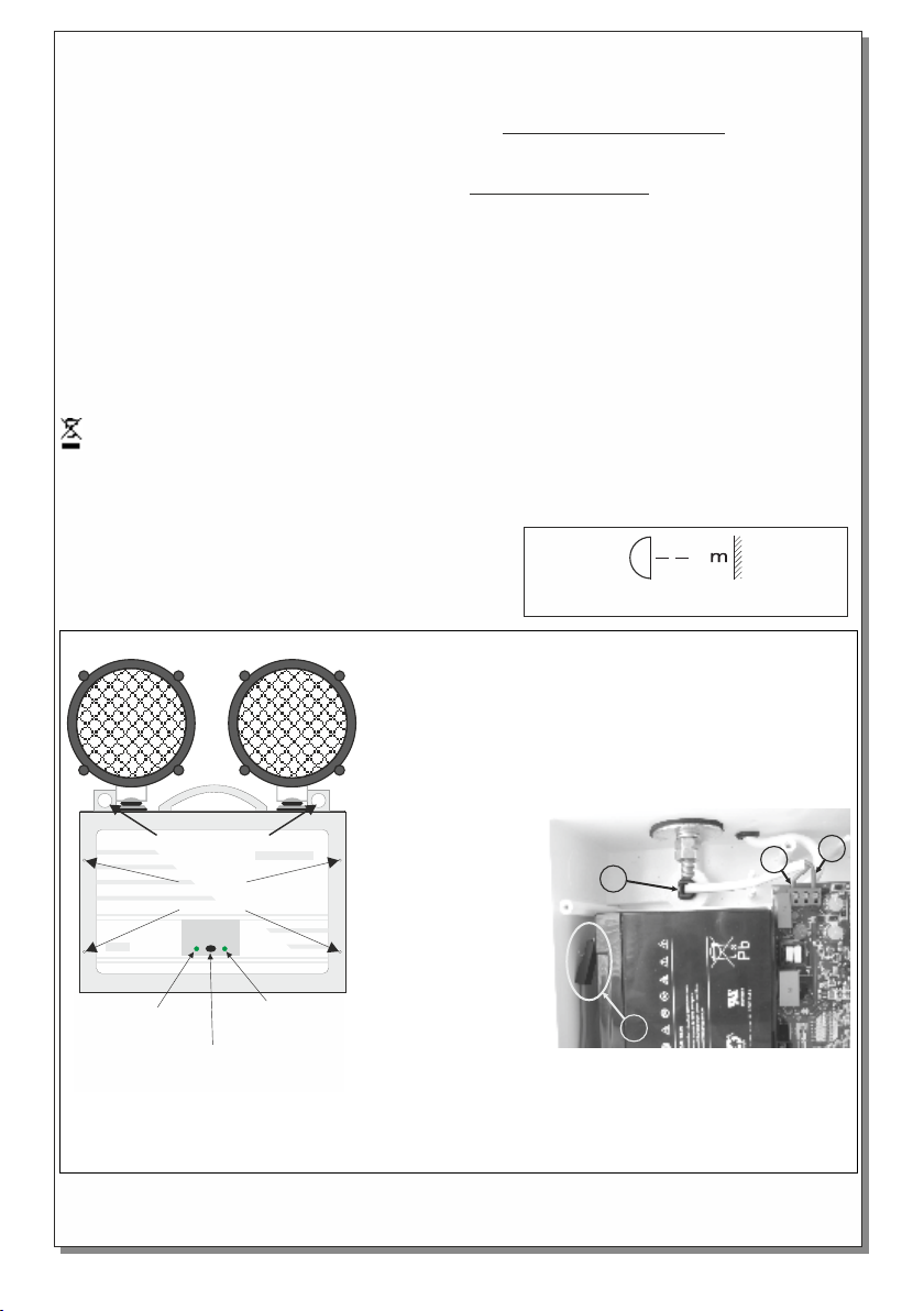
Minimum distance from lighted objects.
Fig. 1
Mo u n t i ng hole s
Cover
retaining
screws
Ch a rge
in d ica t o r
NOTE!!
After finishing the installation you must power the luminaire at least for 24 hours for battery
charging to perform the named autonomy.
Page 2 from 2
TE S T
bu t ton
Po w er
in d ica t o r
1. Install the included mounting accessories to hook the
device from the mounting holes (fig. 1).
2. Unfasten the 4 mounting screws to remove the front plastic
cover (fig. 1).
3. Make sure that the battery’s cables are connected to the
respective poles. Black cable to (-) pole and red cable to (+)
pole.
4. Install the included
cable gland or the
rubber o-ring. Pass
thru the mains cable
and stabilize it by
fastening the cable
gland.
Connect the wires to
the terminal blocks L
for live wire and Ν for
neutral.
5. Refit with care the
front plastic cover, by
fastening the 4
mounting screws
(tightening torque 1Nm).
INSTALLATION INSTRUCTIONS
4
3
923029000_23_023
L
N
 Loading...