

Page 1

OLYMPIA BURNER
OPERATING MANUAL
MODEL: LT-40,45,60,80,100,120,150,
200,250,300,400,500,600,700
OLYMPIA INDUSTRIAL CO., LTD.
Page 2

CONTENT
1. INTRODUCTION OF PRODUCT.
1) BURNER SPECIFICATION.
2) COMBUSTION PERFORMANCE GRAPH.
3) SIZE AND DIMENSION.
4) EXPLODED DRAWING OF BURNER AND PART NAME.
2. HOW TO CONTROL BURNER.
1) BURNER COMBUSTION FURNACE DIMENSION.
2) HOW TO INSTALL BURNER.
3) DIAGRAM OF FUEL CIRCULATION SYSTEM.
4) HOW TO INSTALL FUEL PIPE SYSTEM.
5) TIME CHART.
6) ELECTRIC CIRCUIT DIAGRAM.
3. HOW TO USE MAJOR PARTS.
1) COMBUSTION HEAD DIMENSION.
2) HOW TO ADJUST COMBUSTION OF AIR FLOW RATE.
3) HOW TO DISASSEMBLE, CLEAN AND REPLACE NOZZLE.
4) FLAME DETECTOR.
5) GEAR PUMP.
6) IGNITION TRANSFORMER.
7) FUEL FILTER.
4. GENERAL BURNER OPERATION.
5. HOW TO CHECK BURNER, CAUSE OF TROUBLE AND COUNTER MEASURE.
1) CHECK OF BURNER.
2) BURNER TROUBLE/ACTION TABLE.
3) CAUSE OF COUNTER-MEASURE ACTION.
Page 3
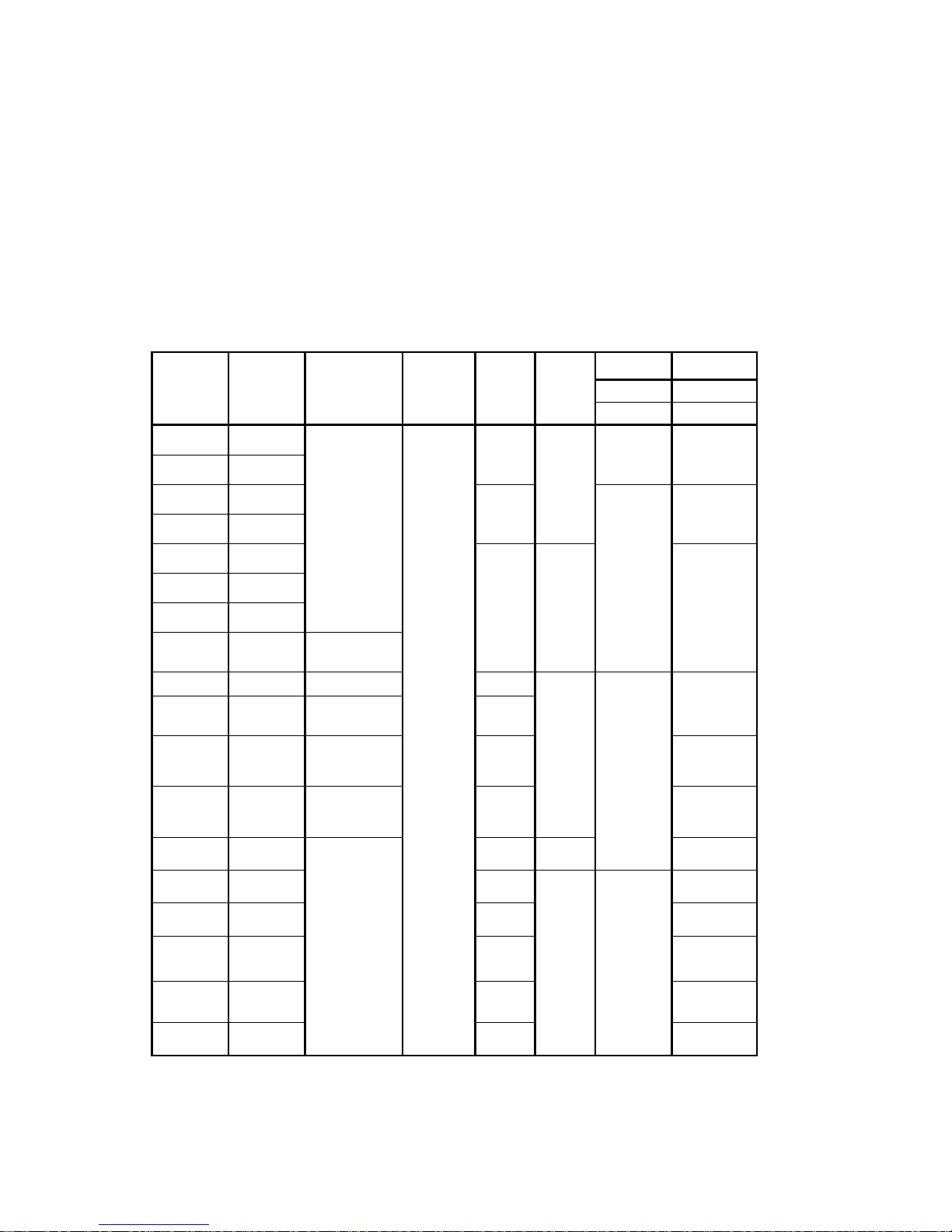
MOD EL
FUEL
MIN/ MAX(kg/
h)
CONTROL
VOLTAGE
(V)
MOT OR
(60㎐ /kW)
GEAR
PUM P
OIL HOSE
MOT OR
POW ER
INHALATION
380V
RETURN
220V
LT-40U
20~40
HI-L OW-OFF
AC3φ220/38
0
O.45
AS47A
PT 1/4"
PT 1/4"
1.2
2.1
LT-40UH
20~40
LT-45U
20~45
0.75
PT 3/8"
PT 1/4"
1.7
3.0
LT-45UH
20~45
LT-60U
25~54
1.1
AN-77
2.4
4.1
LT-60UH
25~54
LT-80U
34~68
LT-80T
34~68
HI-L OW-OFF
or
MODURATING
LT-100
30~98
HI-L OW-OFF
1.5
AJ-6
PT 3/8"
PT 3/8"
3.3
5.7
LT-120
51~123
HI-L OW-OFF
or
MODURATING
2.2
LT-150T
60~150
HI-M ID-LO W-O
FF
or
MODURATING
3.0
4.7
8.2
LT-200T
65~200
HI-M ID-LO W-O
FF
or
MODURATING
4.0
7.5
13.0
LT-250T
71~214
HI-M ID-LO W-O
FF
or
MODURATING
5.5
E-7
11.8
20.4
LT-300T
80~250
7.5
TA-2
PT 1/2"
PT 1/2"
15.8
27.3
LT-400T
108~ 330
11
20.4
35.5
LT-500T
136~ 408
11
20.4
35.5
LT-600T
194~ 583
15
20.4
35.5
LT-700T
167~ 668
18.5
20.4
35.5
1. INTRODUCTION OF PRODUCT.
LT-Series oil Burner is also designed and manufactured upon our well experienced technique
and is made of motor, oil pump, fan, ignition equipment and automation in single body.
the highly pressurized fuel particulates are perfected burnt, which minimizes smoke it has
following benefits.
■ it is easy to check and maintain as a hinge type.
■ All the automatic devices are assembled in an integrated method.
■ it can operate both automatically. emergency operation is possible when the
automatic device is out of order.
1) BURNER SPECIFICATION.
Page 4
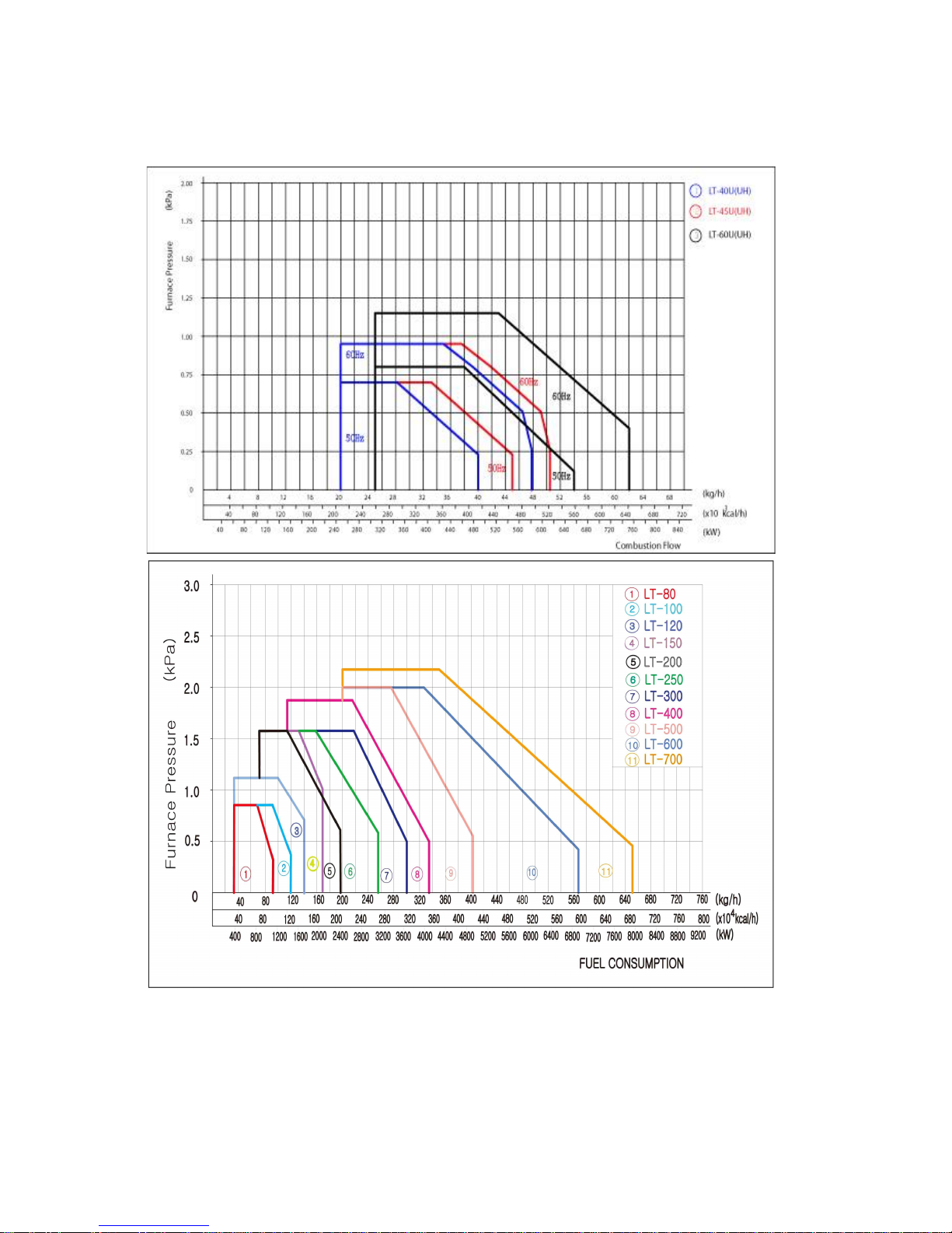
2)COMBUSTION PERFORMANCE GRAPH.
Page 5
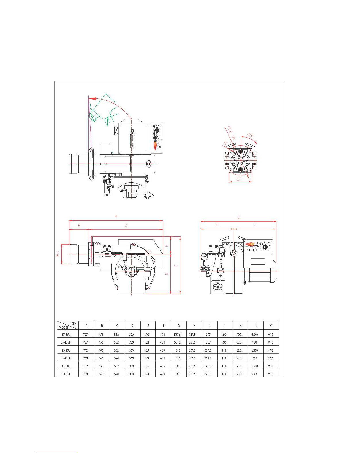
3) SIZE AND DIMENSION.
① LT-40,45,60 DIMENSION
Page 6
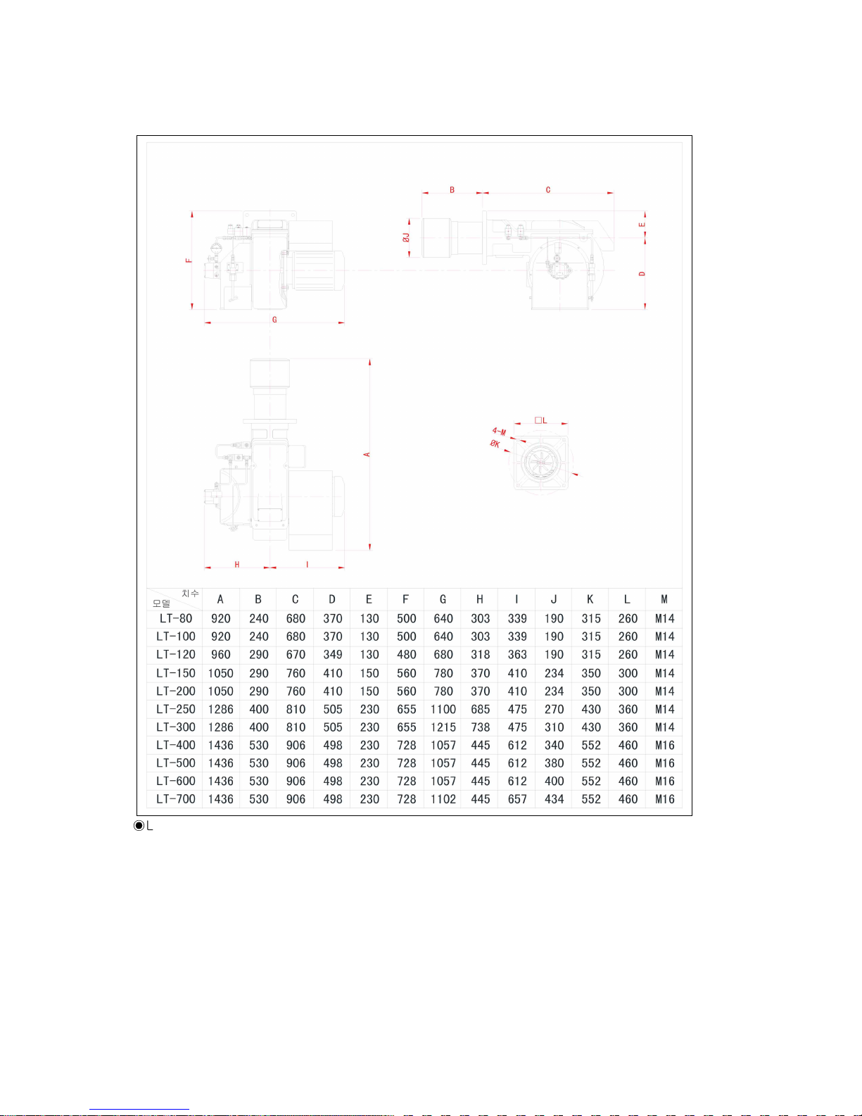
② LT-80,100,150,200,250,300,400,500,600,700 DIMENSION
◉
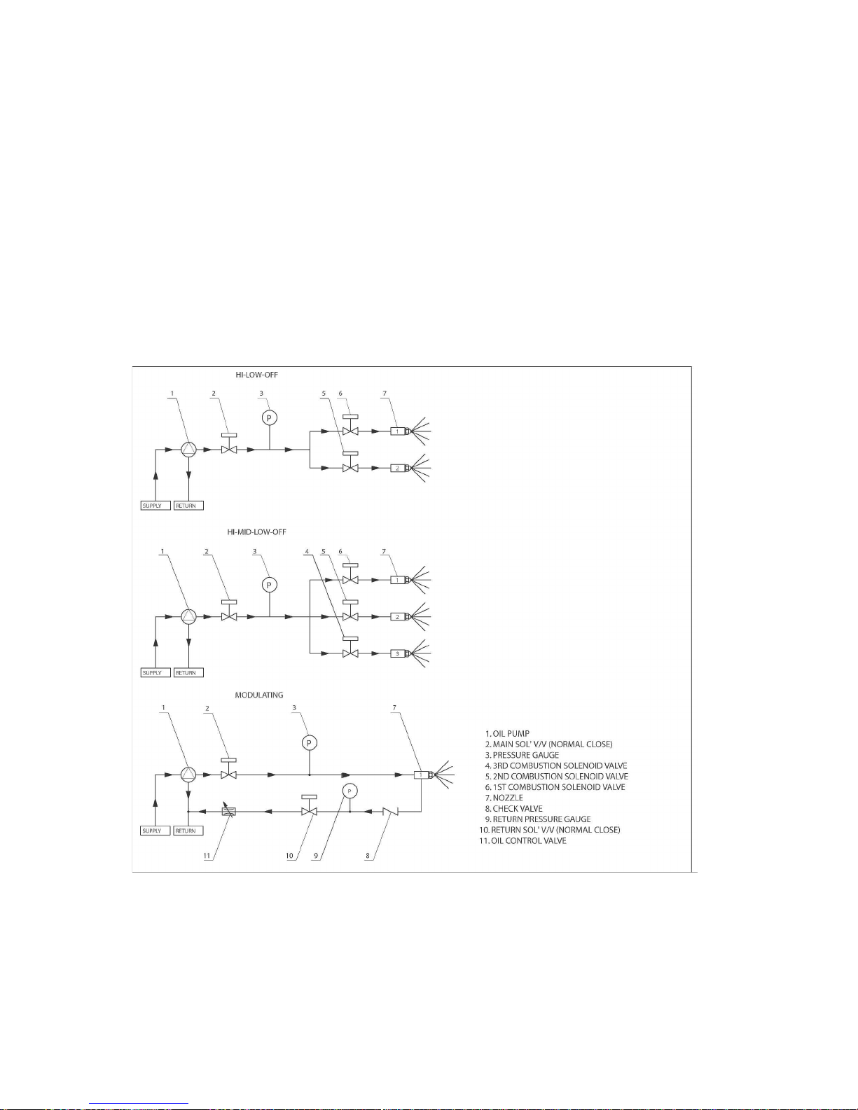
LT-series burner is an hydraulic gun type burner with forced flue fan.
the ignition rate is controlled as follows depending on the number of nozzle.
․ two nozzle: 2-position control( hi-low-off)
․ three nozzle: 3-position control(hi-mid-low-off)
one proportional nozzle: proportional control(modulating)
◉ how to control air flow rate.
․ two nozzle: damper motor or hydraulic cylinder type
․ three nozzle: damper motor type ․ one proportional nozzle: modulating motor type
Page 7
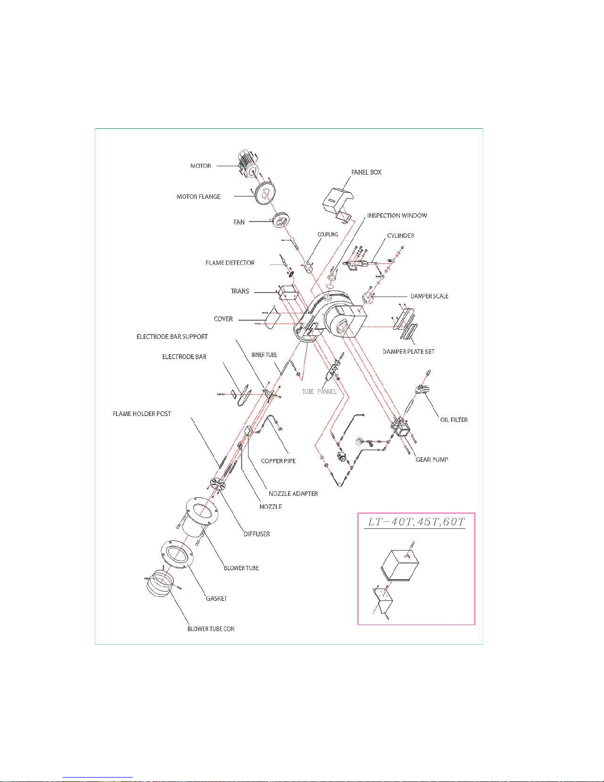
4) EXPLODED DRAWING OF BURNER AND PART NAME.
(1) LT-40U,45U,60U BURNER EXPLODED DRAWING.
Page 8
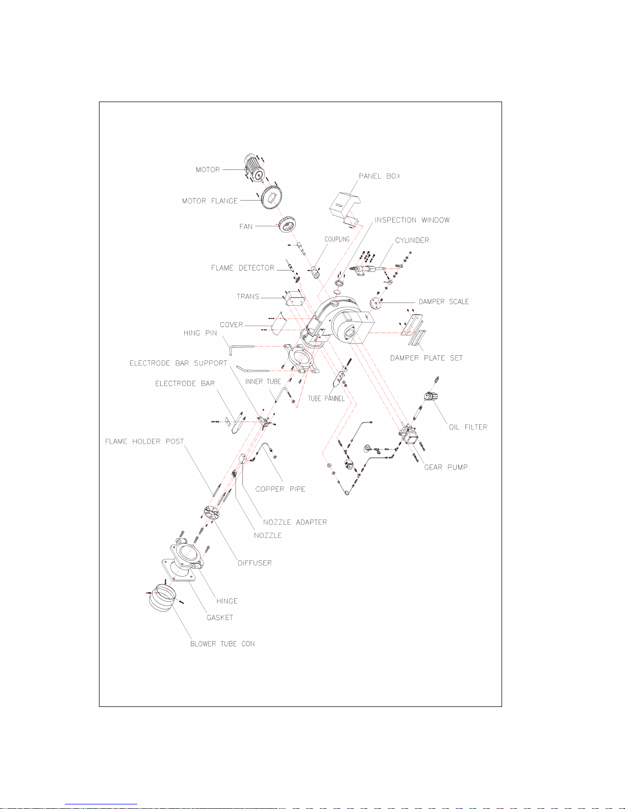
(2) LT-40UH,45UH,60UH BURNER EXPLODED DRAWING.
Page 9
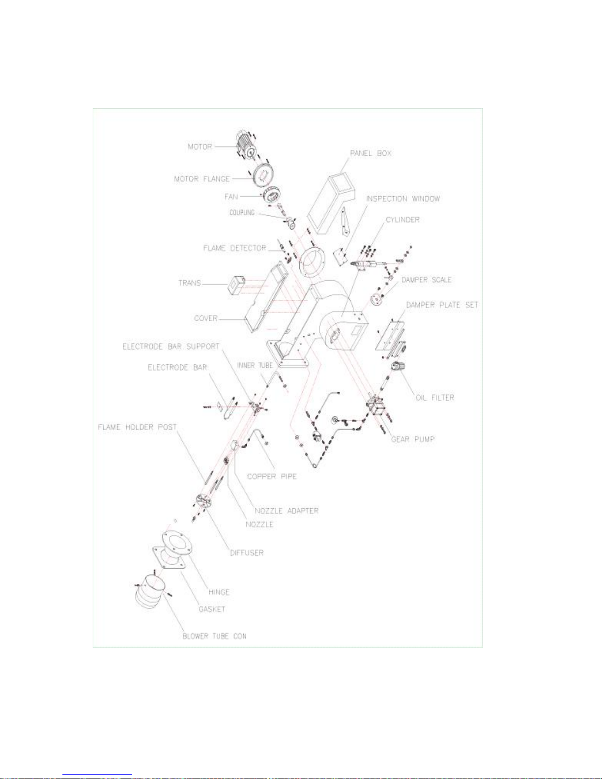
(3) LT-80U,100U,150,200,250,300,400,500,600,700 BURNER EXPLODED DRAWING.
* LT-80T,100T,150,200,250,300 = DAMPER MOTOR
LT-250,300,400,500,600,700 = 3NOZZLE
Page 10
MODEL
LT-40
LT-45,60
LT-80,100
LT-150,200
LT-250,300
LT-400,500,600,700
A
150
171
190
234
270
310
340
380
400
434
B
155
175
195
240
275
315
345
385
405
440
C
160
160
350
290
400
400
D
228
228
315
350
430
430
E
M10
M10
M14
M14
M16
M16
2. HOW TO CONTROL BURNER
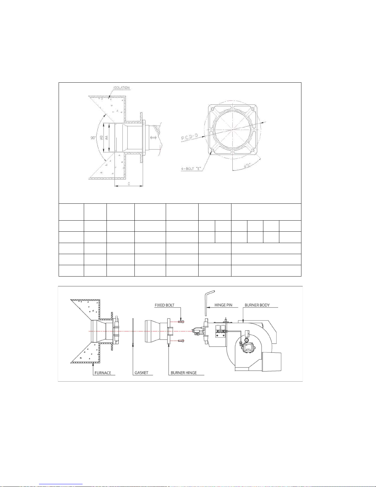
1) BURNER COMBUSTION FURNACE DIMENSION
2) HOW TO INSTALL BURNER.
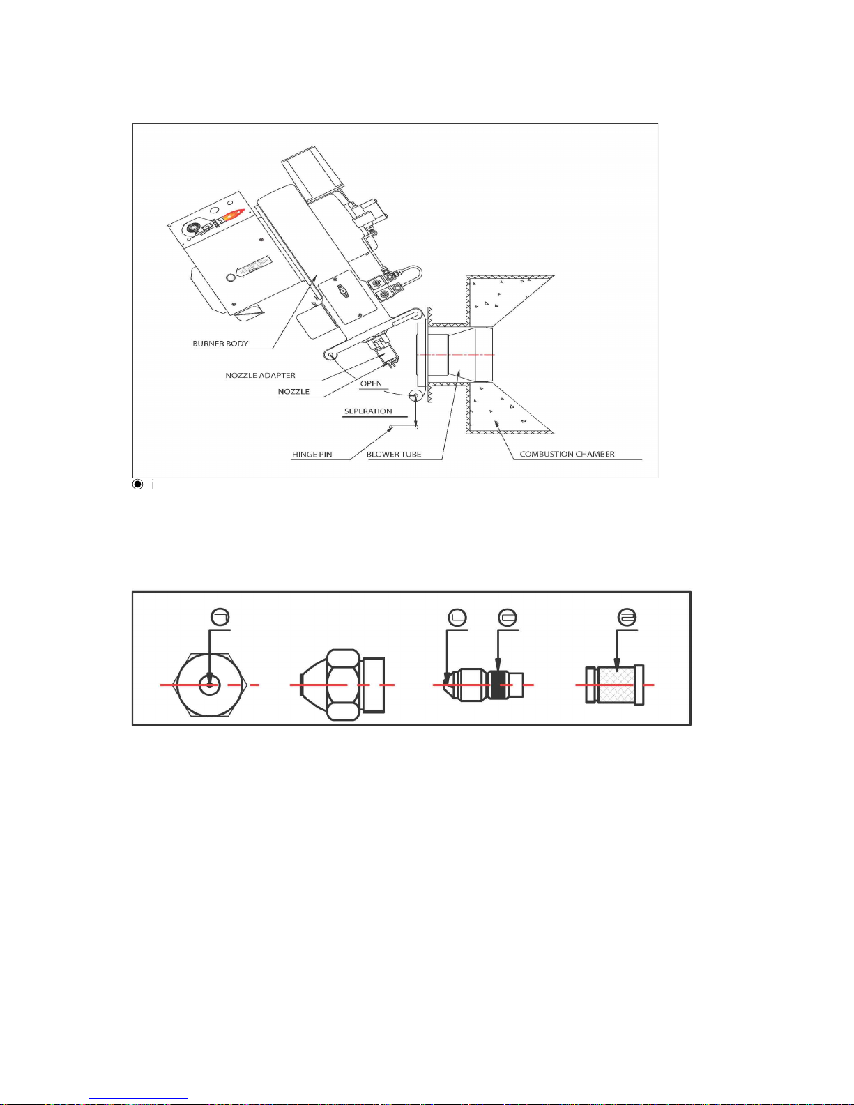
(1) burner assembly sequence(refer to above sketch)
① insert gasket into the burner hinge. insert burner to the boiler fire outlet or
combustion furnace, and tightly fasten.
② after adjusting the burner in the hinge, fix the burner with hinge pin.
Page 11
(2) caution during burner installation
① make it sure to install burner horizontally.
② fasten bolts tightly so that no combustion gas leaks.
③ after installing the hinge-type burner, use care so that no part of ignition bar is
damaged or deformed during assembly of frame.
④ secure enough working space to check and maintain burner.
․ flange tube type burner: LT-40U ~ LT700T.
․ hinge tube type burner: LT-40UH ~ LT-60UH.
3) DIAGRAM OF FUEL CIRCULATION SYSTEM.
Page 12
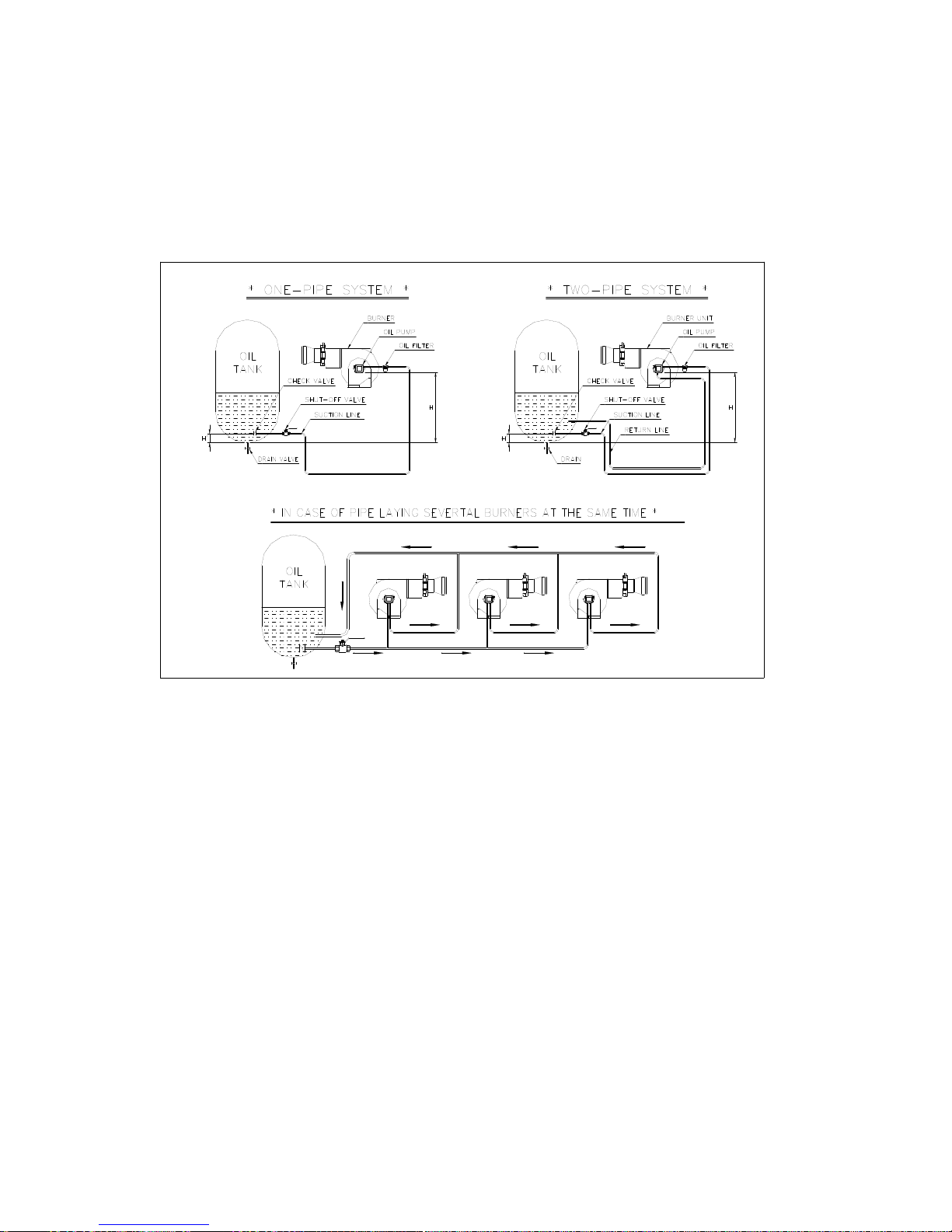
4) HOW TO LAY FUEL PIPE
the installation of the fuel pipe system for the gun type oil burner is divided into
single type pipe installation using the height of oil tank and dual type pipe installation
using sucking power of burner pump.
▶ cautions on laying fuel pipe
① on laying one pipe, it is important to remove by-pass plug, and when laying to
pipes, it must install by-pass plug.
② when oil tank is below burner, "H" its height must be less then 2.4m.
③ the inlet hole should place at 20cm higher then the floor of oil tank in order not
to flow in foreign subtainces.
④ it is recommended that oil pipe be welded in order not to flow in air.
⑤ in case of fixing several pipes, inlet and return pipe must use an enough space
pipe in inside diameter.
⑥ return pipe had better not use valve.(if operates return pipe with clogged states,
it may cause to damage pump and filter.)
⑦ the fuel filter must be used at inlet pipe and fix it with confirming the flowing
direction.
Page 13
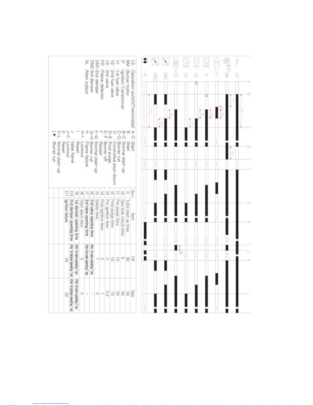
5) TIME CHART
Page 14
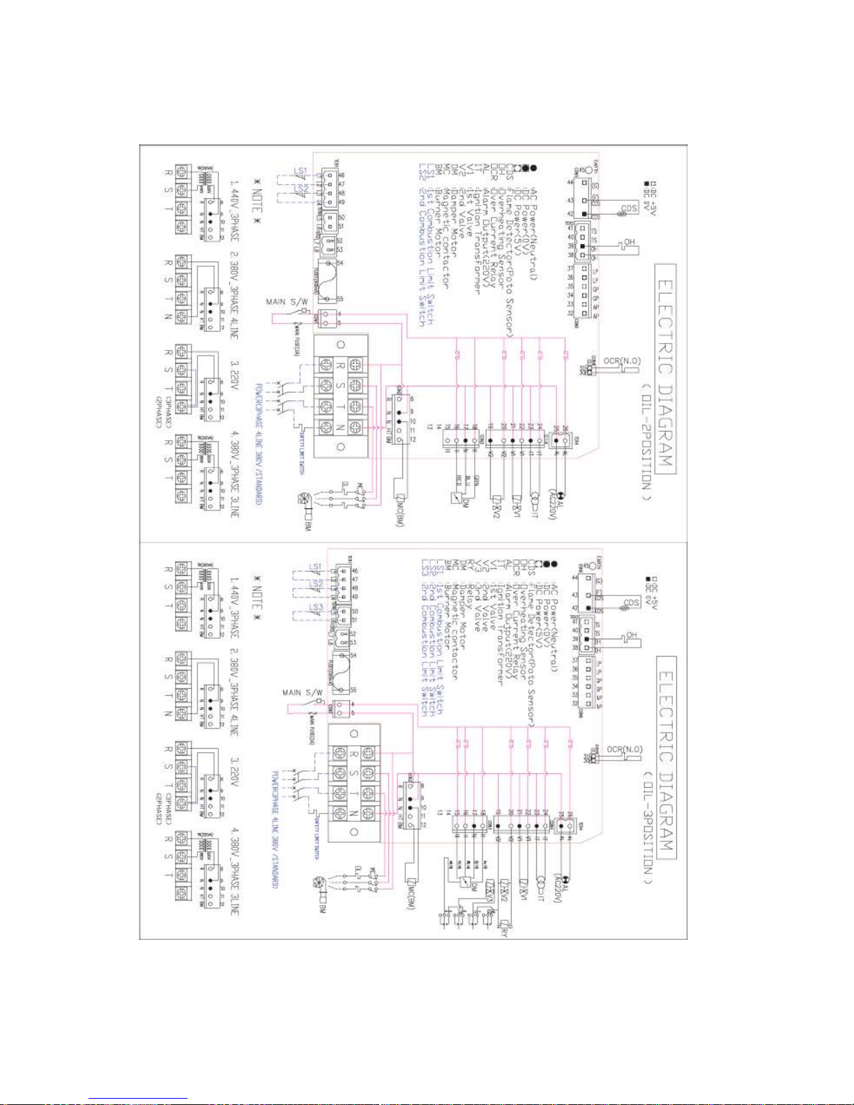
(6) ELECTRIC CIRCUIT DIAGRAM.
Page 15
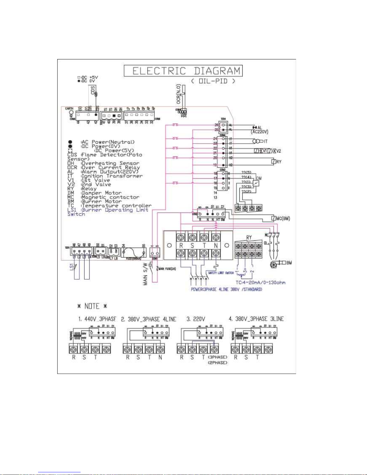
* MODURATING TYPE
Page 16
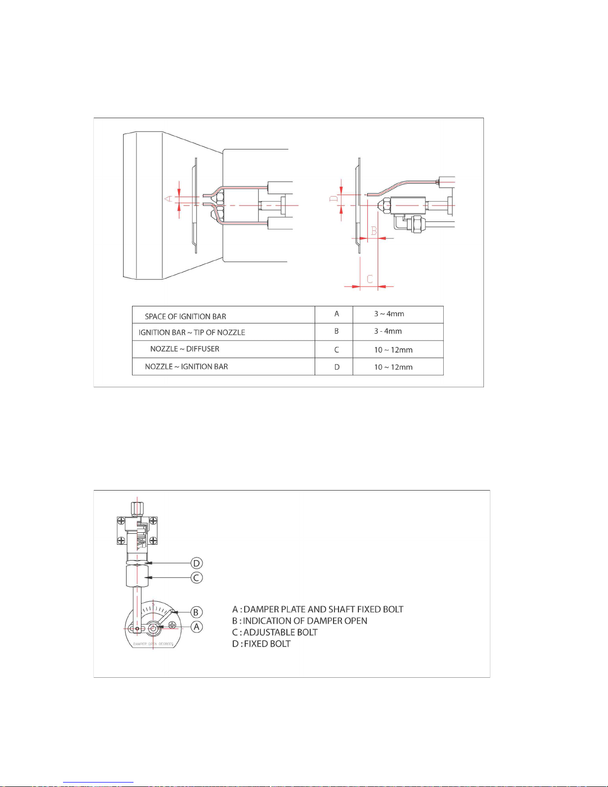
3. HOW TO USE MAJOR PARTS.
1) COMBUSTION HEAD DIMENSION.
◉ in case of adjusting "C" size, be careful not to touch the and of ignition bar with
diffuser or diffuser is not stained with oil.
2) HOW TO ADJUST COMBUSTION AIR FLOW RATE.
(1) hydraulic cylinder.
① structure
Page 17
DM-310
DM-320
② how to adjust
ⓐ
first stage(low combustion) air adjustment : loosen the nut A, and adjust the
damper opening B for normal combustion.
then fully tighten the nut A.
ⓑ second stage(high combustion) air adjustment : loosen the nut D in the high
combustion mode, and tighten adjuster nut C to increase air flow rate until no
smoke coming out from the chimney, when adjustment is over, fully tighten
the nut D so that the adjuster nut is not loosened.
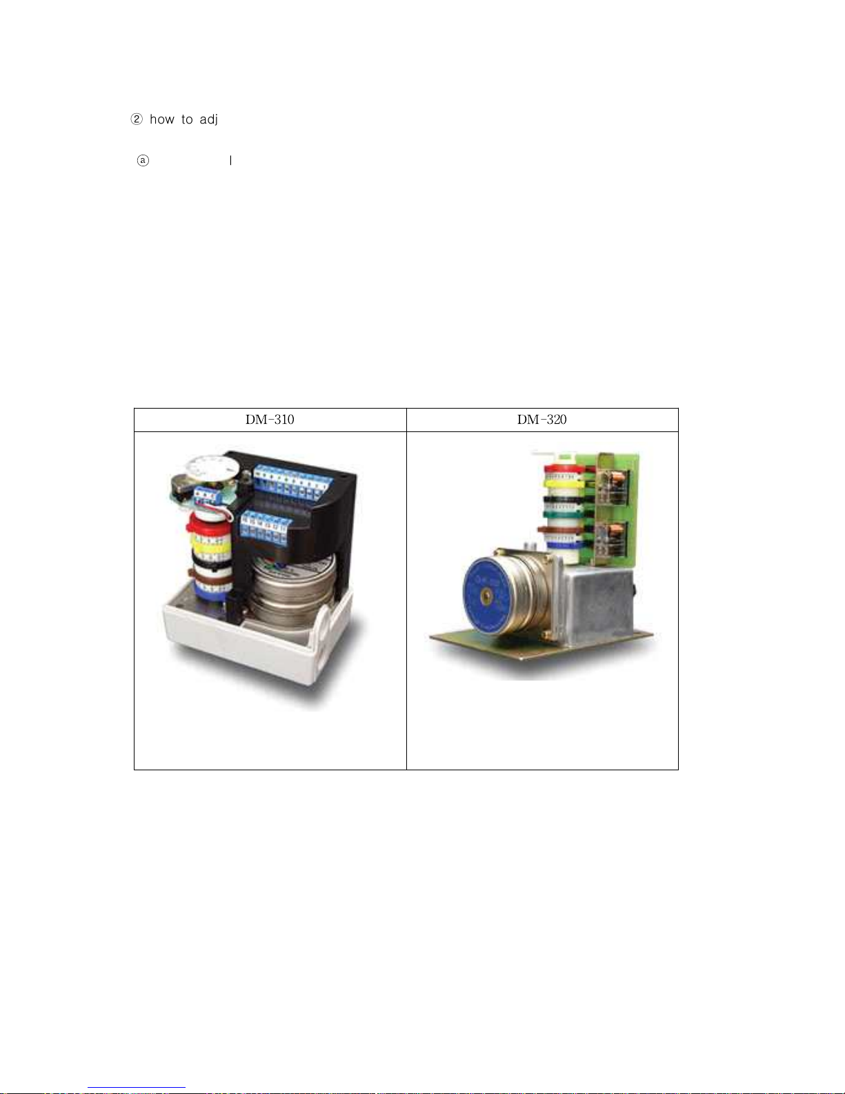
(2) damper motor.
① structure
Page 18
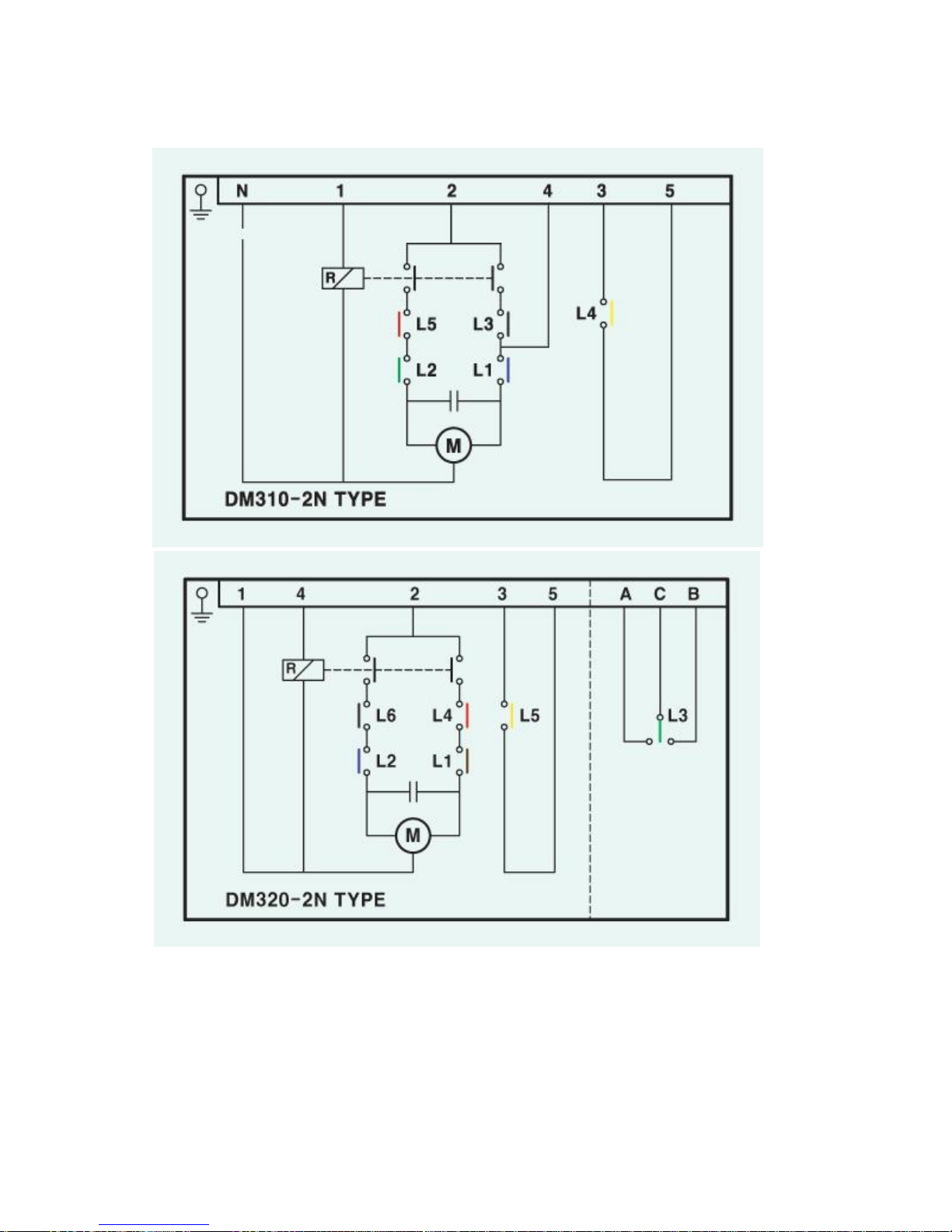
② electric circuit diagram
③ how to adjustment damper
damper gauge consists of from "0"to"10", "0" indicates complete close and
"10"indicates complete open .
㉠ disconnect power.
㉡ adjust each CAM by deciding the position depending on the combustion rate.
Page 19

ex) low combustion damper open : 2/10 open.
medium combustion damper open : 4/10 open.
high combustion damper open : 6/10 open.
ⓐ see each CAM of the damper open scale. accord with marked CAM scale
according to the setting position.
ⓑ when adjustment is over, and adjust damper plate to the low combustion
damper opening using the knob on the opposite side of the motor.
㉢ turn on the power. and adjust damper again while reviewing the operating
conditions of combustion. in this case make it sure to confirm that each switch
turns off sequentially from the low combustion damper CAM.
㉣ overrun protection s/w
when low or high combustion damper CAM is mistakenly adjusted.(for example,
low combustion damper CAM is set below zero in the damper scale or high
combustion damper CAM is set adove 10 in the damper scale) or when the low
or high combustion damper s/w is out of order. press the overrun protection s/w
to stop damper operation.
ⓐ when pressing the low overrun protection s/w.
readjust the low combustion damper CAM when the s/w is out of order,
replace the s/w. when it is completely closed, use the manual adjuster knob
to set in ti the low combustion opening position.
ⓑ when pressing the high overrun protection s/w.
readjust the high combustion damper CAM when the s/w is out of order,
replace the s/w.
3) HOW TO DISASSEMBLE, CLEAN AND REPLACE NOZZLE.
① the nozzle sprays fuel through fine hole(㉠)
② air flow rate and pump pressure are adjustable per the capacity of nozzle which is
specified in terms of spray rate, angle and patten.
③ capacity
G/H (gallon/hour): the capacity id specified as to consume 3.785 liters of
kerosene per hour under the pressure of 7㎏/㎠.
④ 80°: fuel is sprayed from nozzle hole in 80 degree angle.
⑤ when burning conditions are not satisfactory bue to inappropriate splay of fuel,
remove, disassemble and clean nozzle using kerosene.
a) how to replace nozzle.
ⓐ disconnect power.
ⓑ pull out one side of hinge pin to open the burner flame.
ⓒ hold nozzle adapter with spanner, and loosen nozzle counter clockwise.
ⓓ after changing nozzle, check and adjust the place of ignition by with referring to
assembling dimension of combustion head.
ⓔ replace nozzle in the reverse order.
Page 20
◉
in the burner model LT40UH, LT45UH, LT60UH separate burner from the furnace.
then also separate the flange tube, and follow the adove procedure for
replacement.
b) how to disassemble and check nozzle
① separate filter (㉣). clean the filter using kerosene.
② separate the gelical support (㉢) using a screwdriver. clean the groove (㉡) using
kerosene and thin wire. do not use iron wire or needle. otherwise the nozzle hole
may widen.
③ after the nozzle hole is clean, assemble nozzle in the reverse order.
◉ make it fasten it set up.
Page 21
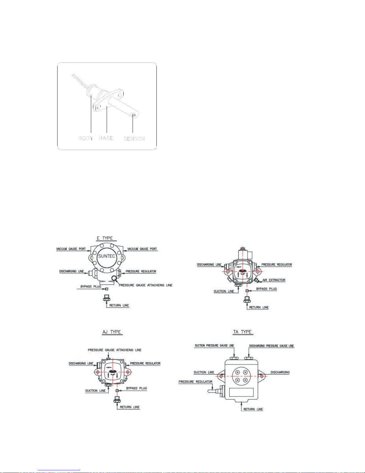
4) FLAME DETECTOR.
① the flame detector detects the igniting
conditions of burner. when it detects that
ignition fails, it stop burner operation as a
safety device.
② when burner stops operation in several
seconds after burner ignitions, check
whether there is a soot or dust on the flame
sensor of the flame detector. thoroughly
remove soot or dust from the flame sensor if
any.
◉ if soot or dust is accumulated on the flame sensor of the flame detector, burner
stops operation. therefore it is required to clean the flame sensor using clean dry
cloth every month.
5) GEAR PUMP.
(1) external drawing and specification.
Page 22
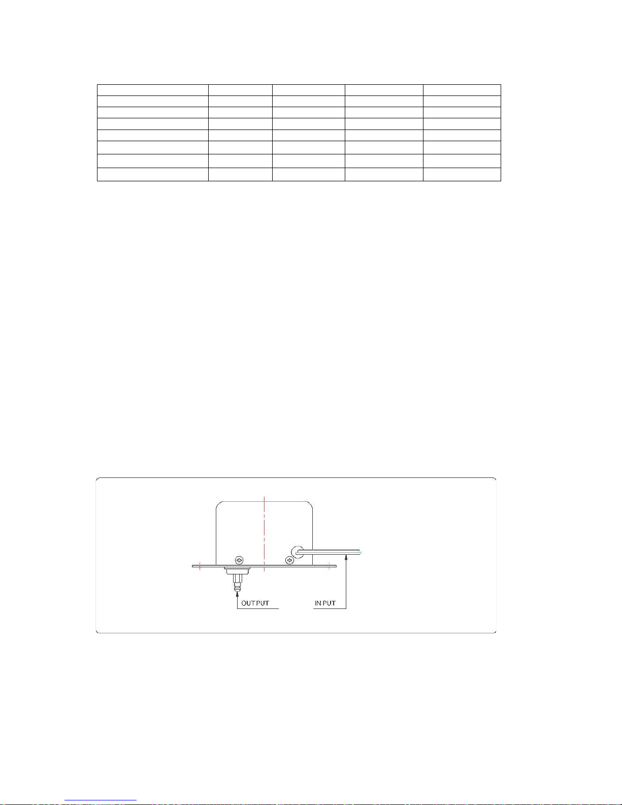
burner model
LT-40U,40UH
LT-45U~LT-200T
LT-200M~LT-250M
LT-250T~700T
pump model
AS&VM TYPE
AJ TYPE
E TYPE
TA TYPE
pump capacity(2850rpm)-ℓ/h
33~47
40~205
110~350
310~750
output pressure-bar
7~14
10~30
14~30
7~40
max. inlet pressure-bar
223.5
5
max. return pressure-bar
223.5
5
max. suction height-bar
0.45
0.45
0.45
0.45
max. rotational speed-rpm
3600
3600
3600
3600
* MODURATING- E TYPE.
(2) how to control.
① function: being connected motor and coupling, it intakes nozzle with adding
necessary pressure for combustion.
② how to adjust pressure: turning the(-)groove in the pressure adjuster hole
clockwise/counter clockwise, pressure is increasing/decreasing.
(3) how to purge air from the pump
① turn the gear pump air purge bolt counterclockwise 3 to 4 times with spanner,
operate burner. then air bubble comes through the air exhaust hole of the gear
pump. then clean oil discharges. then stop burner operation, and fully tighten
the air purge bolt. then operate burner.
② if air is not completely removed within 16 seconds, burner stops operation. when
pressing re-start button, burner resumes operation. when air is completely
removed after repeating this procedure, burner will operates normally.
◉ then completely tighten the air purge bolt with spanner.
6) IGNITION TRANSFORMER
① external drawing
② function
it is an ignition to raise input voltage from 220V to 17Kv and outputs the raised
voltage to the ignition bar for a normal burner operation.
◉ if the ignition transformer is in trouble, no ignition occurs.
Page 23
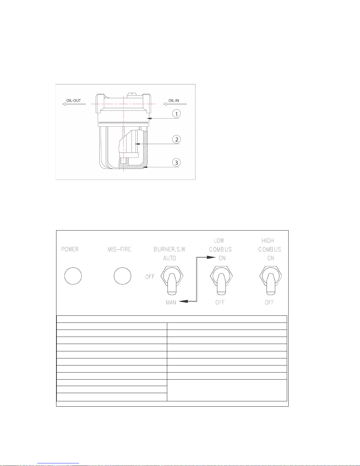
P O W E R
automatic operation
manual operation
burner s/w turns on
burner s/w turns on
auto/man s/w : auto
auto/man s/w : manual
lock release
inter lock release
blower/gear pump operate
blower/gear pump/ ignition transformer operation
operation of ignition bar
low combustion s/w : on
low combustion valve : on
high combustion s/w : on
flame detecter check the ignition
hydraulic cylinder or damper motor operates
hydraulic cylinder or damper motor operates
safety device does not operate in the manual mode,
use manual mode for emergency operation only.
continue to check conditions of flame during manual
operation
high combustion valve : on
automatic operation by inter lock
☞ auction: take care of the ignition transformer as high voltage is applied to the
ignition transformer.
7) FUEL FILTER.
▶ how to handle fuel filter
․ the fuel filter removes foreign
substance from fuel.
․ when burner does not generate
flame as no fuel is fed even if
oil pipe is contained in the fuel
tank, clean the fuel filter.
․ when fulling out a container ③
below the plastic cap①, you
find a filter② in the container.
․ clean the filter using kerosene
or light oil, replace filter.
◉ fully tighten the filter to prevent penetration of air after cleaning the filter.
4. GENERAL BURNER OPERATION
Page 24

5. HOW TO MAINTAIN, CHECK AND SERVICE BURNER.
1) CHECK OF BURNER.
▶ check the followings prior to burner operation.
① after checking the water level of boiler, pressure and fuel feed rate, open the
valve between tank and oil pump.
② check whether the working voltage and fuel meet the burner specification.
③ discharge air from the fuel pipe system.
④ check whether or not the burner nozzle corresponds the boiler or furnace
capacity..
▶ maintenance of burner
① clean the ignition bar if it is contaminated.
② clean nozzle and nozzle adapter.
③ if soot is accumulated on the diffuser, burner fails to ignite.
remove the soot from the diffuser.
④ check and clean oil filter if required.
⑤ check and clean flame detector if required.
Page 25
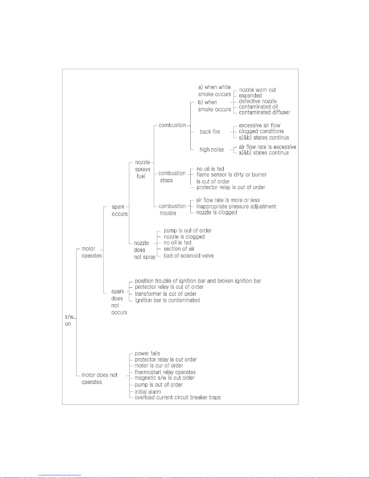
2) BURNER TROUBLE/ACTION TABLE
Page 26

3) CAUSE OF TROUBLE AND COUNT-MEASURE ACTION
trouble
major cause
action
motor does not
operate.
1. flame sensor detects danger.
signal, and stops operation.
2. protector relay is out of order.
3. motor is out of order.
4. gear pump is out of order.
․ reset after removing
the cause of trouble.
․ replace and repair.
․ replace and repair.
․ replace and repair.
motor operates but
does not ignite.
1. ignition bar is inaccurately
adjusted or damaged.
2. transformer or lead wire is out of order.
3. pump discharge pressure drops and air
suction.
4. no oil is sucked in.
5. electronic valve is clogged or out of
order.
6. combustion air flow rate is too much or
less.
7. nozzle is clogged.
8. inlet pipe is damaged.
9. coupling is poor.
․ adjust ignition bar
position and replace.
․ replace and repair.
․ raise discharge.
pressure discharge air.
․ check valve and clean
filter.
․ replace and repair.
․ adjust damper.
․ replace and repair.
․ replace and repair.
․ replace and repair.
when combustion
stop immediately
after ignites.
1. flame sensor is contaminated.
2. flame sensor is out of order
3. protector relay is out of order.
․ clean
․ replace and repair.
․ replace and repair.
combustion is
unstable or smoke
occurs.
1. hydraulic pressure is inappropriate for
spray.
2. nozzle is clogged
3. combustion air flow rate is too much or
less.
․ adjust spray pressure.
․ replace and repair.
․ adjust damper.
in case of
operated by
manual but no
operated by
automatic.
1. protect relay is out of order.
2. protection of protect relay reset button
3. flame sensor receiving light from out
side
․ change or repair.
․ reset after removing
the cause of trouble
․ reset after removing
the cause of trouble
flame is red.
1. short of air.
․ open damper.
flame is blue and
white
1. combustion air flow rete is too much
․ close damper
 Loading...