

Page 1

~ 1 ~
OOllyym
mbbeerryyll
®
®
W
Woooodd &&
M
Muullttii--FFuueell SSttoovveess
Introduction
Congratulations on purchasing a genuine Olymberyl® Stove. When cared for properly, these
high quality, finely crafted c ast iron stoves and fireplaces will offer many yea r s of reliable
performance. This instruction manua l has been developed to ensure optimum performance
from the Olymberyl® stove and fireplac e range. I t's very important that you thoroughly read
and understand all instructions b efore using your new stove or fireplace.
Check Building Codes
When installing, operating and m aintaining your stove, follow the guidelines presented in
these instructions, and make them available to anyone using or servicing the stove.
Your city, town, county or province may require a building permit to install a solid fuel burning appliance.
Always consult your local building inspector or authority having jurisdictio n to determine what
regulations apply in your area.
Kindly save these instructions for future references
Page 2

~ 2 ~
Stove Safety
When properly maintained and operated your stove should give you many years of service,
however there are important safety aspects of these products that you need to be aw are of
when operating a stove.
1. The term Multi-fuel refers to any of the main commercially available solid fuels such
as coal, wood, turf, anthracite, briquettes. Never use liquid fuels such as oil or kerosene when lighting or refreshing the fire or at any other time. Do not store liquid fuels near stove.
2. The burning of wood gives off gases which can be extr emely dangerous. T h e stove is
designed that under normal op erating circumsta n ces these gases pass up the flue
chimney system and cannot escape into your home, however it is important that your
flue system is properly installed and that you check all joints regularly to ensure that
there are no cracks or gaps, check the door sealing rope and replace when damaged.
We recommend a smoke alarm be fitted in rooms where stoves are installed. Do not
use stove in a room where negative pressure conditions may occur, such as through
the use of extraction fans unless an adequate air supply into the room is ensured, as
this may draw air through the stove and cause p r oducts of combustion to escape into
the room.
3. Creosote and soot may accumulate in your flue pipe and chimney. This may ignite,
causing a chimney fire. If you suspect a chimney fire evacuate people from the building, close down the air controls on the stove and call the Fire Department. To prevent
the accumulation of soot or creosote, check flue and chimney regularly and clean a s
necessary. Good burning, hot stoves will generally cause a lot less build-up than slow
burning stoves, likewise dry wood wi ll cause less build-up than wet wood. We recommend a fire extinguisher be available where stoves are in operation. In the event
of a chimney fire do not re-light the stove unt il i t and the flue chimney system have
been thoroughly checked and repa ir ed as necessary.
4. Stoves get extremely hot and should no t be touched when lit. When young children
are in the area, we recommend the use of a suitab l e fir e guard around the stove. Always wear protective gloves when reloading stove.
5. Never over-fire your stove. If external parts of your stove are glowing red then the
stove is over-firing and your draught settings should be reduced. Never interfere with
the draught mechanisms or adjust your air settings outside those limits set when the
stove is manufactured. Never use a fan to sup ply air to the stove or to extract air
from it.
6. All users of the stove should be aware of the contents of this manual. Please leave
this manual where it is accessible to stove u sers and do not allow anyone to use the
stove that is unfamiliar with it s c orrect operation.
7. Never use the stove if any parts are missing or damaged, only use genuine parts as
replacements. Never modify your stove.
8. Never use a fan to supply air to the sto ve or to extract from it.
Page 3

~ 3 ~
Before installing your stov e
You need to consider the following to ensure the safe operation of your stove.
• Provision of adequate air to supp ort efficient combustion of the fuel.
• A well sealed flue/chimney system, hereinafter referred to as the “flue system ”.
• The protection of combustible materi als in proximity of the stove.
Adequate provision air
It is essential for the safe and efficient use o f your stove that you provide an adequate air
supply to your stove. This may mean the provision of an outside air supply to the room,
especially if there are extraction unit s such as cooker hoods or clothes dryers in the vicinity. Failure to do so will mean that fuel is burned i neffic iently causing smoke and blac kening the glass and may also cause smoke to come back into the room. As a simple check
for this open a door or window in the room and check if the stove burns more efficiently.
Well sealed flue system
Only materials and items approved for solid fuel stoves should be used for your stove as
fuel.
Under no circumstances should you use aluminum or galvanized steel pip es f or your stove
flue.
Always fit pipes with the narrow sid e down, this allow any creosote to run down the inside of the pipe and not to come out and cause an unsightly mess and possible fire hazard. All joints in the flue system should b e sea l ed with fire cement and/or an appropriate
fire resistant rope or gasket.
Pipe bends should be kept to a minimum and we do not recomm end using m ore than 2
bends on any installation. Flues must not pass through ceilings, floors, attics, roofs, or
combustible walls without adequate and approved insulation being provided to protect
combustible materials.
The chimney and flue provide a m eans of taking combusted fuel from the stove, as well
as a draught to enable the stove to work. It is essential that the flue system is kept in
good condition and there are no breaks or cracks allowing contact with any other combustible materials of the house. It is also essential that the flue system is kept clea n and
seals are maintained to ensure the draught is not lost.
The open end of the flue system must be a bove the height of the apex of the building
and any other obstructions, such as trees, which are within 3 meters (10ft) of the flue
system. Failure to do this will affect the effic iency of the stove and may cause down
draughts which will mean dangero us products of combustion are emitted into roo m.
Under no circumstances should the flue pipe be less than 5” (125mm) internal d iameter.
Page 4

~ 4 ~
Installation
Unpacking and preparing you r stove for ins tallation.
1. Remove your stove from the outer packaging and place on floor. Please inspect stove
and check that it is not damaged in any way. Never attempt to use a stove that has
been damaged.
2. If you are installing the stove yourself, pr oceed as follows. However, if you ar e unsure about any aspect of stove installation, please contact your dealer and he will discuss installation with you or put you in touch with an experienced stove installer.
3. Open the fire door using the handle and remove the contents from the firebox.
4. Gently lay the stove on its back. Remove scr ew s fr om 4 corners of base and fit one of
the legs to each corner of the stove. Tighten bolt to ensure leg is secure to base of
stove. Fully stand the stove upright.
5. If using back flue outlet go to 6, if using top flue outlet, remove hob and lay it upside
down on soft surface, remove hob blanking plate from underside of hob by taking out
2 screws, remove flue blanking plate from top outlet and fit to back outlet making
sure it is properly sealed with ceramic rope or approved fire cement.
6. Move the stove into position. Do not drag the stove as this may damage the legs,
screws or base.
7. Connect flue pipe to stove, seal all j oints with ceramic rope and/or approved fi r e c ement.
Stove Clearance
It is extremely important that you respec t required installation distances and that you respect local installation regulations. This is for your safety! The manufactur er i s not responsible for the product, if it is not i nstalled following these recommendatio ns. These
clearances may only be reduced by means app r oved by the regulatory authority.
A combustible surface is anything that can burn (i.e. sheet rock, wall paper, wood, fabrics
etc.) These surfaces are not limited to those that are visible and also include materials
that are behind non-combustible ma terials. If you are not sure of the combustible nature
of a material, consult your local fire officials.
Page 5

~ 5 ~
Single wall
connector pipe
Double wall
connector pipe
A – Chimney Connector to backwall
16.5” (419 mm)
10.5” (267 mm)
B – Chimney Connector to sidewall
22” (559 mm)
18” (457 mm)
C – Chimney Connector to cornerwall 20” (508 mm) 15” (381 mm)
D – Unit to backwall
14” (356 mm)
8” (203 mm)
E – Unit to sidewall 14” (356 mm) 10” (254 mm)
F – Unit to cornerwall 11.5” (292 mm) 6.5” (165 mm)
For connectin g into existing Chimney:
The Chimney should be swept prior to installation and smoke tested to ensure it is sound.
The Chimney must not have any hollow sections present, these should be filled to ensure
that any soot or tar, etc. does not build up which may present problems when sweeping
the chimney. Hollow sections within the c hi m ney may also present problems with t he
chimney draw. The connecting flue pipe must be sealed to the chimney with fire cement
and high temperature resistant rope as required. This is usually done into a register
(Blanking) plate with an access door/hatch to enable chimney sweeping. Particula r l y
large chimneys may require lining as the flue temperature may not get warm enough to
provide a suitable up-draught.
Minimum diameter should be no less than the outlet size of the stove, 25to 50mm lar ger
is ideal. Where the stove outlet is less th an 150mm this dia meter should be no less than
125mm when only burning smokeless fuels or a minimum of 150mm for any fuel types.
Horizontal flue.
Soot/Access Door
F
ill Void
Fire retardant
Rope seal required
Allow area for collecting soot build up.
Minimum distance should be no less
than The outlet diameter of the stove.
Build up opening
Parallel Installation
Corner Installation
Page 6
~ 6 ~
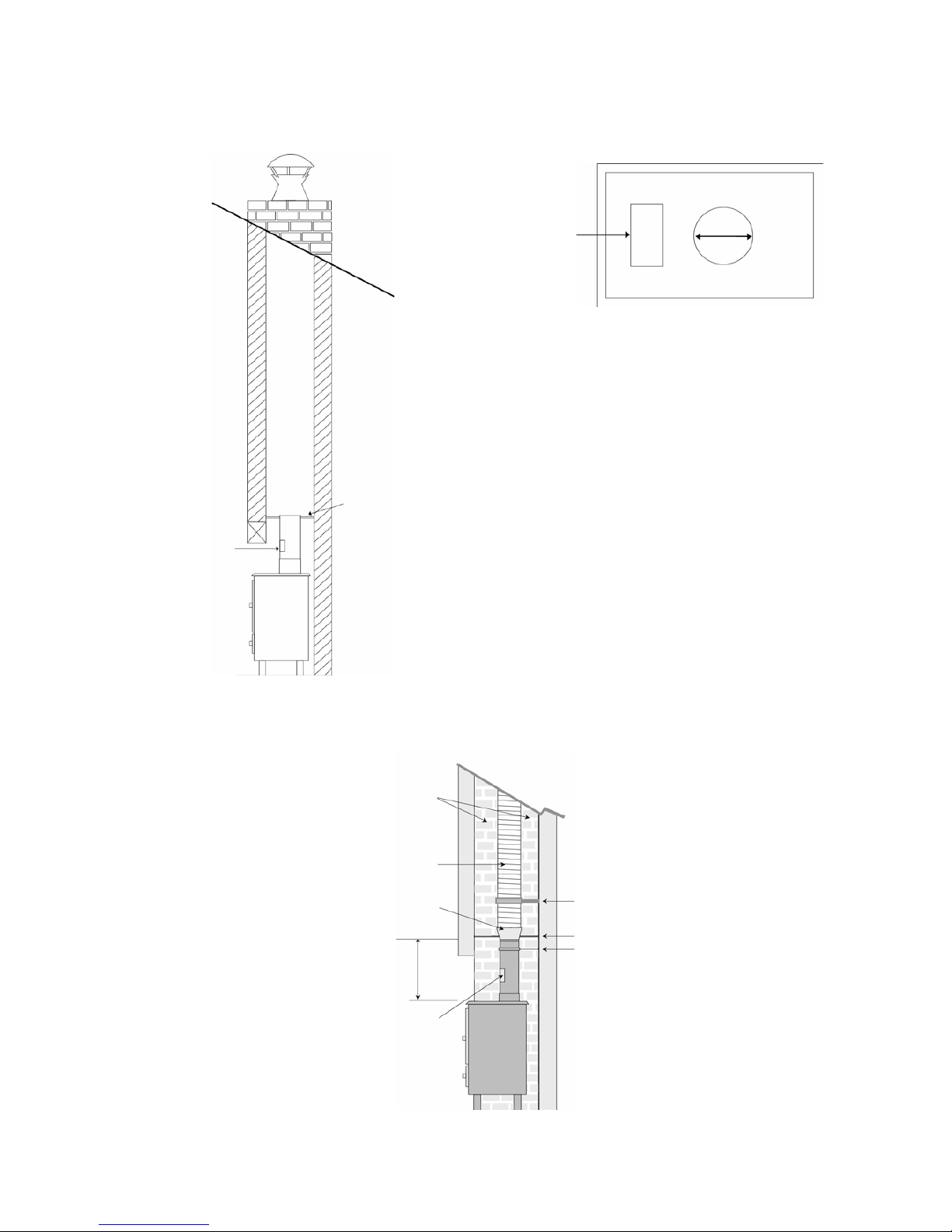
Some typical installations are shown as following
Sealed door to
access chimney for swee
p-
ing & inspec
t-
i
ng.
FLUE
The Flue must be
1.5mm thick rust
resistant steel and 3 times it‘s
diameter away from combustible materials. For example
150mm Flue Pipe must be
450mm away from combustible m
a-
terials.
Access
door
Non-combustible
register plate. Minimum
1.5mm thick rust resistant steel or heat resi
s-
tant board.
TOP FLUE OUTLET
If the chimney is not s
ound, i.e. found to be leaking after a smoke test then the chimney must
either be repaired or a flexible liner may be used, ensure the liner is the correct type for
Multi-Fuel applications. See diagram below:
It is recommended that
this area is insulated or
backf
illed.
Flexible Liner
SW to TW Adapter
Maximum Recommended distance is
1.5mtrs of c
onnecting fluepipe to existing
chimney or Twin Wall Class 1 system
S
upport Bracket for Flexible Liner.
Register Plate
S
upport Bracket for the
c
onnecting fluepipe
Vitreous Fluepipe with
stainless access door.
Page 7
~ 7 ~
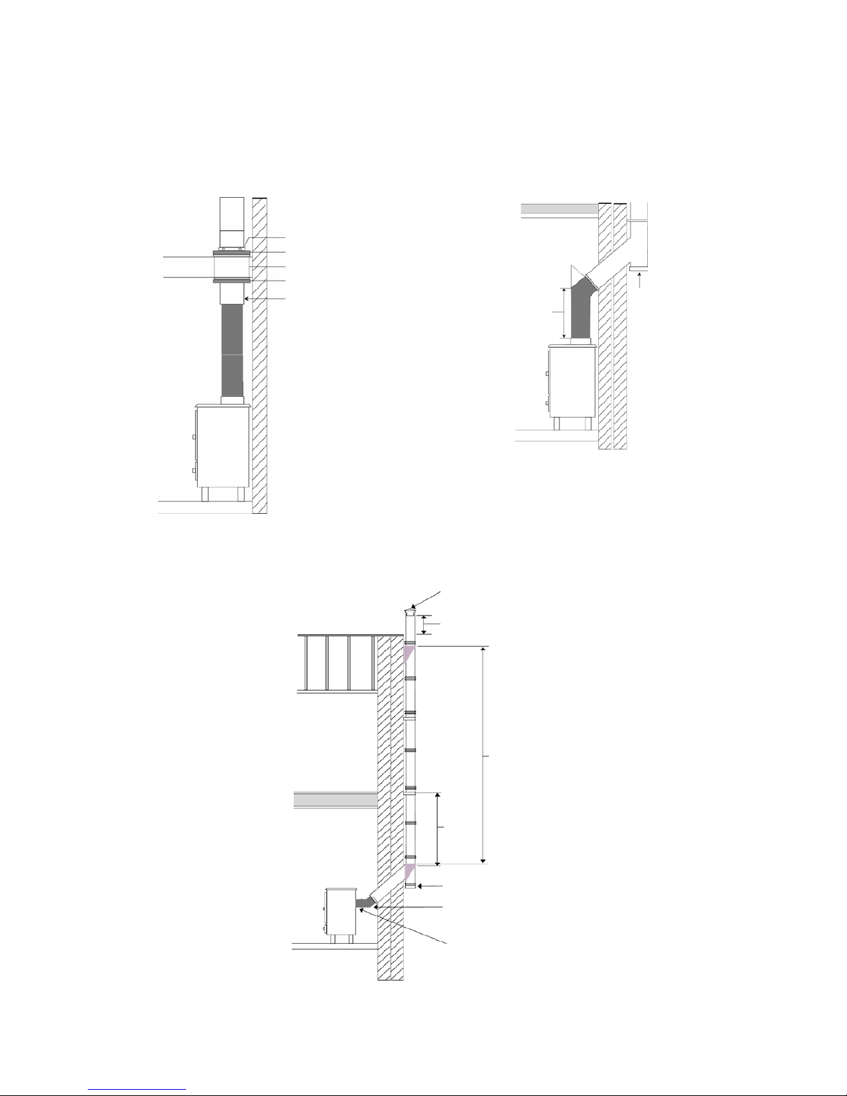
For Installations where no Chimney exists
The Connecting flue pipe from the Stove should connect to the Twin Wall Insulated fl ue
pipe, ensure this flue pipe is the correct type for Multi-Fuel applications.
Some typical installations are shown as following:
Support Collar
Fire Stop Spacer
Radiation Shield
Fire Stop Spacer
Twin Wall Flue Pipe must
start at least 150mm below combustible surface.
45°
600mm
minimum
Rain cap/Cowl
Access for soot
removal
600mm minimum
Access for soot removal
45° degree elbow
Maximum horizontal
150mm
Page 8
~ 8 ~
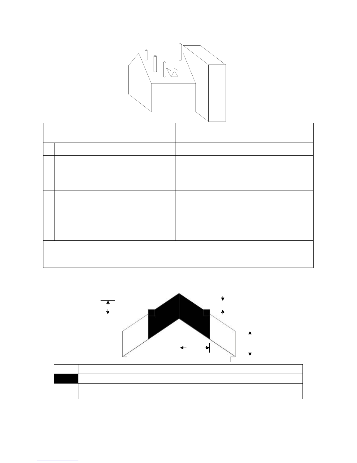
The Chimney/Terminal Outlet must be no lower than the minimum positions shown in t he
diagram below:
A
D
B
C
Point where flue passes through weather
surface (Notes 1,2)
Clearance to flue outlet
A At or within 500mm of the ridge. At least 600mm ab ove the ridge.
B Elsewhere on a roof
(Whether pitched or flat)
At least 2300mm horizontally from the nearest
point on the weather surface and:
A) at least 1000mm above the highest point of intersection of the chimney and the weather surface; or
B) at least as high as the ridge
C Below (on a pitched roof) or within 2300mm
hori- zontally to an open able roof light,
dormer window or other opening . (Note 3)
At least 1000mm above the top of t he opening.
D
Within 2300mm of an adjoining or adjacent
building, whether or not beyond the boun
dary.
(Note 3)
At least 600mm above the adjacent building.
Notes
1) The weather surface is the building external surface, such as its roof, tiles or external walls.
2) A flat roof has a pitch less than 10 degrees
3) The clearance given for A or B, as appropriate, will also apply
For terminations above easily ignited surfaces i.e. thatched roofs then minimum outlet
positions are shown below, this diagram needs observing i n conjunction with the
above diagram:
1800mm
600mm
Outlets should be above the
shaded areas.
B B
At least
2300mm
1800mm
Area Location of flue outlet
At least 1800mm vertically above the weather surface and at least 600mm above the ridge
B At least 1800mm vertically above the weather surface and at least 2300mm horizontally
from the weather surface.
Upon completion of the installatio n the Chimney/Flue must be smoke tested prior to the
stove being lit.
Page 9

~ 9 ~
Operating Your Stove
Fuel
Your stove is designed to burn a range of solid fuels such as coal, wood, turf (peat) and
etc.; it is not designed to burn,
• Paper or cardboard, other than small amounts used to light stove.
• Treated or painted wood
• Synthetic fuel or logs that are not approved for solid fuel stoves
• Household rubbish
• Liquid fuels
• Plastics
Burning these or other products for which the stove was not designed may damage the
stove and cause a fire hazard or release toxic fumes
Fuel should be stored in a dry place; wood should be dried for at least 1 year. Wet wood
may cause serious creosote, which may damage your flue system and even your stove.
Therefore the use of wet wood is strongly discouraged.
The approximate calorific (Heat) Value of the most common fuels is:
Turf or Peat 4.0 kWh/kg
Briquettes
5.3 kWh/kg
Wood
5.5 kWh/kg
Brown coal nuggets
5.8 kWh/kg
Standard coal
7.9 kWh/kg
The figure shown for wood is based on dry hardwood.
First operation of stove
You should begin using your stove b y l ighting small fires which get progressively bigger.
We recommend a series of about 5 small fires befo r e you put the stove into full service.
Allow the stove to fully cool between each o f these fires. There may be some smell and a
small amount of smoke from the stove dur i ng the initial operations. This is perfectly
normal and is merely the curing of the sto ve paint. Opening a window or door to provi de
additional ventilation will help allevia te this.
Air controls
Your stove needs air to burn the fuel. This air is supplied through the spin valve at t he
base of the door and through the slots over the glass. Primary air, as the name suggests,
is used for the initial burning of the fuel. Secondary air is used for secondary com bustion,
which makes the sto v e more efficient, reduces the emissions and i s also used to keep t h e
stove glass clean. Wood burns better with the air over the fire bed and when burning a
lot of wood, you should use the secondar y air supply more.
Page 10
~ 10 ~
The settings of both of these air contro ls very m uch depends on draught and local conditions and after a few fires, you should have a good idea of the best settings for your
stove. The air controls should be fully opened when lighting the fire. Once the fire is established, the controls may be adjusted as required. Reducing the air intake will cause the
stove to burn slower. This may cause som e blackening of the stove glass, but this should
burn off once the stove is burning brightly again.
Refueling
Before refueling your stove, tur n the air supply to high for a few moments until there is a
good fire in the stove. This will ensure there is no build-up of harmful g ases in the stove
when the door is opened and will also get the new fuel burning quickly and not allow it to
kill the fire.
To reload the stove, open the door and feed the fuel in slow l y using tongs or a small shovel. Do not overfill the stove. It is alwa ys better to put in small loads often rather than b ig
fills less frequently. Close the door gently after stove is reloaded.
You should always wear protecti ve gloves and use tongs when tending a hot stove.
Ash removal
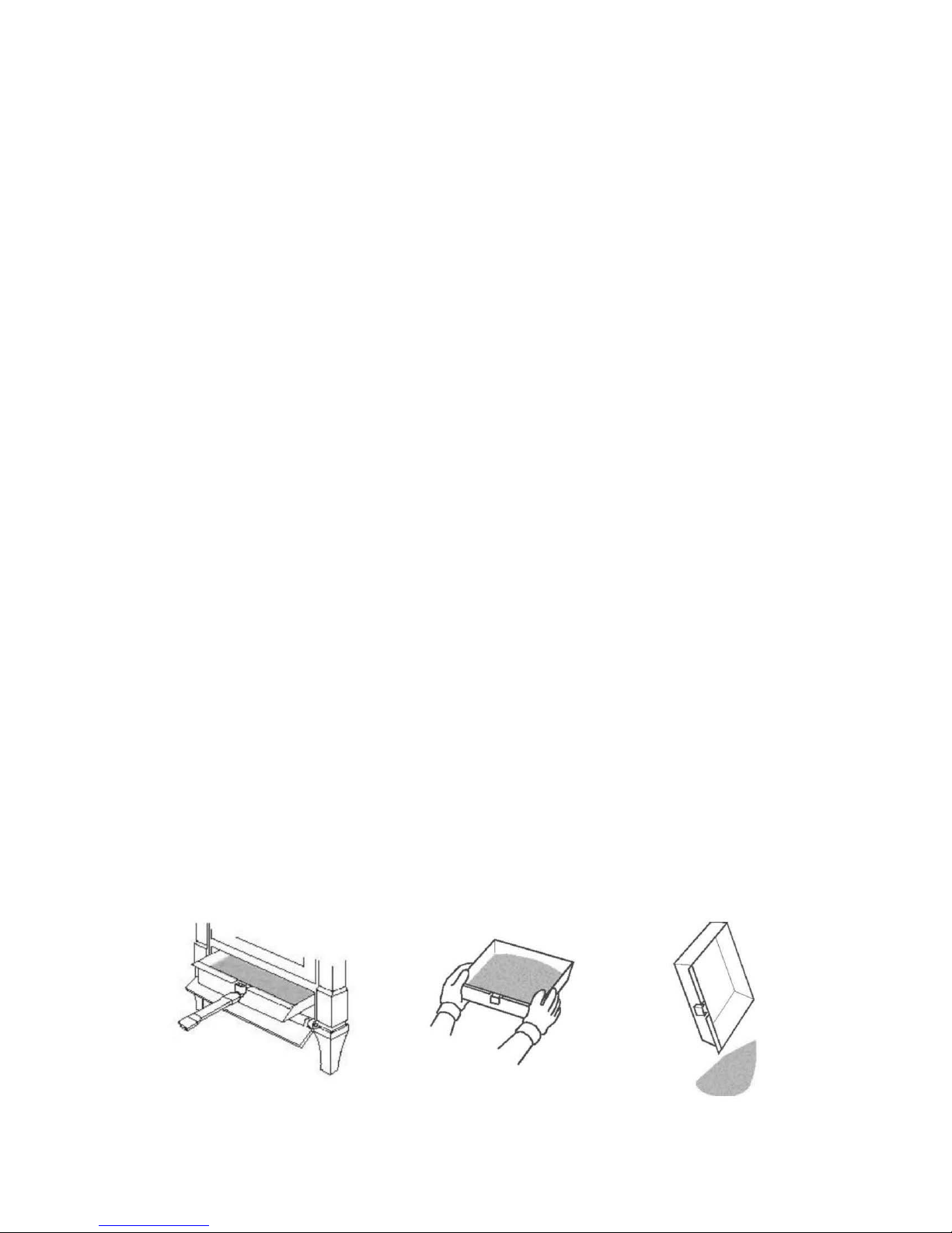
Your stove is fitted with a shaker grate to remove the ash from the firebox. Use the operating tool to move the shaker knob forward and back. This will allow the ash to fall into
the ash pan under the fire bed. This can also be achieved by using a poker.
When ash has built up in the ash pan, it should be emptied. Failure to do this will cause
ash to build up around the grate and may cause your grate to warp or burn out. It is especially important when burning fuel wit h hi gh ash content that you keep your grate clear
and your ash pan emptied regularly, so as not to damage your grate. Clear t he grate with
the shaker bar or a poker regularly.
To remove the ash, open the stove door and use the operating tool provided to lift the
ash pan out of the stove. If possible, this should be done before lighting the stove when
the ash is cold. Even if the ash appears to be cold, it should be placed in a noncombustible container as there may be hot ash in the center of the pile. You should always wear protective gloves when removing ash from the stove.
Page 11

~ 11 ~
This stove is not d esigned to operate with the door open. Always close the stove door
when you have taken out the ash tray and l eave closed while disposing of the ash. Only
reopen to put ash pan back into the stove a nd close immediately afterwards.
Care of glass
At times, especially when the air controls are turned to low settings or when damp wood
is used, the stove glass will blacken. This is caused by fuel that is not completely b ur nt,
but the build-up on the inside of the glass w il l normally burn off when a good hot fire is
established in the stove.
There may be times however when you need t o clean the glass. To do this, use a soft
cloth and a non-abrasive glass cleaner. Onl y ever clean the glass when the stove is cold .
When loading fuel into the stove, always make sure it is not protruding out thro ugh the
door opening, as this may break the gla ss when you close the door. This is especially relevant when loading logs. Alwa ys c l ose the door gently.
If the glass does crack when the stove is lit, let the fire die out. Do not open the door until the stove has fully cooled. Replace the glass wit h the specified replacement part before
re-using the stove.
Overnight burning
Your stove is designed to allow overnight burning. To do this, put a good fuel b ed into the
stove and allow it to burn for about 15 minutes so as not to kill the fire. Then close the
secondary air supply at the top of t he door and turn the primary air inlet to almost closed .
The exact setting of this depends on local conditions, but we suggest you begin with
about a ½ turn open. If the fire burns away, then next time close it a little more. If the
fire goes out, you need to try with it a little more open. After a couple of nights, you wi ll
find the setting that best suits the loca l c onditions of your stove.
When you return to your stove, fully open both air controls until you have a good fire and
then set to normal operating levels. Do no t add fuel until the fire bed is hot and red. Then
add a little for the first time and allow that to ignite before adding more. During overnight
burning, the stove glass will blacken, but when a hot fire is established aga in this shoul d
burn off.
Stove Maintenance
Check stove regularly
Initially, we recommend you check your flue system at least once per month. After the
first few months you will notice a pattern of so ot and creosote build up and you can then
determine an inspection interval for checking soot and creosote build up that is suitable
for your stove installation.
Other checks, as listed below, should be carried out at least twice per year. If you notice
anything wrong at any time it should be rep aired immediately. Never use a stove that is
in any way damaged or has a damaged flue.
Page 12

~ 12 ~
1. Check your flue system for build up of soot or creosote and for signs of damage to
joints. To check flue outlet remove top of baffle by lifting a nd pulling out at end. Use
a flashlight to check flue outlet. Clean and repair as necessary. Always replac e top
baffle before relighting stove.
2. Check that glass is not cracked o r chip ped and that sealing rope is in good condition.
Replace as necessar y .
3. When the room is dark, use a strong flashlight to check the sealing of the stove at
the edge and corners for leaks. Any leaks or cra c ks found should be repaired with fire
cement or damaged parts should be replaced with genuine spare parts.
4. Check that stove door is tight and well sea l ed when closed. Place a strip of paper into
the stove and close the door, try to pull out paper. You should feel some resistance
to your pull, check several point s around the door. If it pulls out too easily, replace
the rope and seal in place with a suitable high temperature sealant.
Replacing parts
Always use genuine replacement parts. Only ever make replacements when the stove is
cold.
Surface finish
The stove should only be cleaned using a damp cloth. Some cleaning products may leave
stains on the stov e su rface. Never use abrasive cloths as these may scratch the surfa ce.
Painted stoves can be re-painted by using a good quali ty, high temperature stove paint.
When re-painting, make sure there is plenty of ventilation and follow the manufacturer’s
instructions. Allow the paint to fully dry before lighting the stove and allow extra ventilation for the first couple of fires as some fumes may emit from the stove as the paint cures.
Wetback (Boiler)
Check the surface of your boiler regularly, if you find a build-up of creosote scrap away
with a flat steel scraper. This build-up of creosote will insulate the boiler and reduce the
heat absorbed by the water.
Trouble Shooting
Fire not burning
A stove not burning is generally caused by either a shortage of air and/or incorrect or
damp fuel. If fuel is not the problem c hec k:
That the air controls are opened.
There is no blockage in the flue system.
That the open end of the flue is abo ve the height of any nearby obstructions.
That there is a sufficient air supply into the room and that this supply is not being
taken by an extractor fan.
Page 13

~ 13 ~
Glass blackens
Glass usually blackens when:
The fuel is not being burned efficientl y because of starvation of air.
Bad quality or damp fuel is being used.
Balance between primary and seconda r y air is incorrect.
Try to introduce more air into the stove, espec ially through the secondary air control on
the top of the stove door as this air flows do wn over the glass to help burn off the creosote. For optimum efficiency a lways use a good quality wood.
Smoke in room
If the stove is properly installed it should not emit any smoke into your room. Should this
happen, check that your room is not air tight. This can easily b e c hecked by opening a
door or window. If the smoking stops you need to provide an additional air supply into
the room. If this is not the problem, check if your chimney is blocked or obstructed and
that you are not getting a down draught caused by the location of the open end of the
flue pipe or chimney.
If the problem persists contact your dealer and ask him to get your chimney and stove installation checked.
Fire burning too quickly
This is usually caused by too much d r aught or air.
Firstly try reducing the air supply to the stove by closing down your air controls, if this
fails then you may have damage to the sealing.
Check the condition of the door seal ing rope and the joints within the stove.
If neither of these solve the problem yo u m ay have too much draught on your chimney
and you may need to fit a damper valve into your flue system. You should not install a
flue damper without consulting a specialist. Never install a damper that can completely
block your flue or chimney. Contact your dealer to discuss this.
Chimney fire
Chimney fires occur when soot and c r eosote that have built up in the flue system ignite.
If the stove is operated properly and the flue checked and cleaned regularly then chimney
fires should not occur. These fires can be very dangerous and must be avoided. Try to
maintain good, hot fires in the stove whenever possible and at least once in every firing
open the air controls and allow the stove to burn on full for a short while until the entire
fire bed is glowing red. Check your flue system regular ly for build-up of soot and creosote
and clean as necessary.
Chimney fires can be detected by sparks c oming from the top of the chimney, a roaring
sound coming from the area of the stove o r chimney or vibration in the stove or chimney.
In the event of a chimney fire, close the air co ntrols, evacuate the building and ca l l the
fire department. Do not relight the stove after a chimney fire until the stove and flue ha ve
been checked and any necessary repair s have been carried out.
Page 14

~ 14 ~
ADDITIONAL INFO (FOR BOILER MODEL ONLY)
Boiler Connection
The advanced Back-Boiler fitted in your Stove must be installed in Compliance with all relevant Building Regulations and in accordance with Central Heating Standard EN 12828
whilst complying with local Wat er Supply Regulations. Guidance and further info r m ation
is available from your Local Wat er Supplier. The Stove must NOT be operated unti l the
back-boiler is connected and has water connected to it, operating the stove before the
Back-Boiler is connected may cause damage to the boiler and stove alike, this will also
terminate the guarantee. A suitably qualified water heating engineer is recommended for
connecting the Boiler of the Stove, this may be a separate installer to that of the Chimney/Flueway. This Back-Boiler may be effect ively i nstalled or linked in with an existi ng
gas or oil circuit if a neutralising vessel is installed.
The ready fitted boiler connections have 1“BSP thread s. The Back-Boiler in your Stove is
only suitable for Indirect Closed Ci r c ui t Systems for heating Domestic Hot Water and Radiators, the quantity of which will requi r e c alculating by your installer and is largely dependant upon the size of radiators, pipe work length and pipe work diameter.
When the Back-Boiler is heating dom est i c hot water an Indirect Domestic Hot Water
Cylinder with an integral heat exchanger is required, this is readily identified on the Cylinder as the protruding threads are male fitting, do NOT confuse this with an unsuit able
Direct Cylinder which has female threads. Pipe work where applicable from the BackBoiler to the open vented gravity Feed & E xpansio n Tank must rise continuously and will
require a 25mm water clearance from below the warning pipe. All pipe work and fittings
must comply with all relevant fitting and European standards.
A Drain Off Cock must be fitted to all low points of the system. A method of allowing
complete drain age of water from the syst em must be incorporated. An adequate means
for preventing backflow of water int o other parts of the system must be provided.
The Indirect Closed Circuit System may also require, (dependant upon type of installation):
A thermostatic valve to be fitted to all r adiators (unless heat leak).
A Heat Leak radiator , towel rail or similar appliance fitted into the primary flowi ng
circuit to dissipate excess heat from the Back-Boi ler. This appliance must be at
least 10% of the Back-Boiler output and must NOT be fitted with a contr ol valve.
A pump in the primary system to assist the flow.
Pipe thermostats to prevent over heating or cold water flowing through the circuit.
Injector Tees to assist the circulatio n.
The Back-Boiler must be tested upon completion of installation.
Usage of thermostat
As for the large boiler type stove HFB-443, there is one more primary air inlet at the back
of the stove. It can be controlled either by hand or by a thermostat. If your option is a
stove with a thermostat, the thermostat is set at close or “0” position by the manufacturer
and you may reset it at an open position according to your own needs. Our suggestion for
re-setting the thermostat is as under:
Set it to 0 ~ 3 position when you connect your stove to 5 ~ 10 radiators to heat an area of 70 ~ 110 ㎡
Set it to 3 ~ 6 position when you connect your stove to 10 ~ 15 radiators to heat an area of 110 ~ 150 ㎡
Set it to 6 ~ 8 position when you connect your stove to 15 ~ 18 radiators to heat an area of 150 ~ 180 ㎡
Page 15
~ 15 ~
The thermostat is a safety device. It aut omatically closes the air inlet when the water
temperature is more than 85±3℃, so that the water doesn’t get too hot. And it automatically opens the air inlet to the set open position when the water temperature is lower
than 80±3℃. This way the thermostat makes the water temperat u re not change too
much.
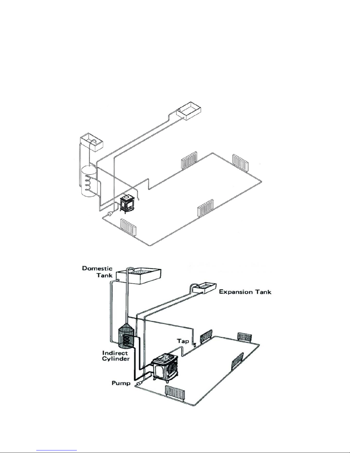
WATER HEATING SYSTEMS DIAGRAM
For HFB-332/HFB-243
```````````````````````````````````````````````````````````````````````````````````````````````````````````````````````````````
For HFB-443
Note: This diagram illustrates the b asic principal of water heating systems and m ust not
be regarded as a working drawing.
Page 16
~ 16 ~
Condensation
CAUTION WHEN FILLING
When filling the boiler with water for the first time, the cold water entering the water
jacket can cause condensation to form on the surfaces of the appliance (inside and o ut)
In certain conditions this condensatio n c ould result in a considerable amount of water, in
some cases enough to fill the bottom of the appliance. This could be even worse if the
house has recently been re-decorated, wet plastering or any other work undertaken
which could result in high humidity.
Precautions must be taken to ensure that t his build up of condensate does not overflow
from the appliance onto surrounding fabric of the room e.g. carpets.
NOTE – THIS CONDENSATION IS NORMAL DURING FILLING AND DOES NOT
INDICATE A FAULTY OR LEAKING STOVE
SEASONAL USE
If this appliance is unused for lengthy periods of time it should be periodically c hec ked to
ensure that condensate is not building up within the stove.
NOTE – THIS CONDENSATION IS NORMAL DURING FILLING AND DOES NOT
INDICATE A FAULTY OR LEAKING STOVE
If the stove is going to be not used for a very long period of time it is recommended to
drain the system.
NORMAL RUNNING
During normal running this condensation should be minimal if the system is fitted with a
low limit thermostat. This low level thermost at prevents the system pump for running until the stove has r eached temperature.
TECHNICAL DATA
Model Output
Overall
Efficiency
(%)
Size (mm)
H x W x D
Flue Size
(mm)
Net
Weight
(Kg)
HF-217 BabyGabriel 4.5kw 75 565mmX375mmX414mm 125mm (5”) 83kg
HF-332 Gabriel 5kw 70 670mmX450mmX390mm 125mm (5”) 89kg
HFB-332 Paladin 7kw 75 670mmX450mmX390mm 125mm (5”) 98kg
HF-233 Victoria 8kw 70 680mmX535mmX510mm 150mm (6”) 116kg
HF-233i
Victoria Ⅱ
9.5kw 76 680mmX535mmX510mm 150mm (6”) 123kg
HFB-243 Olive 11.5kw 78 680mmX535mmX510mm 150mm (6”) 124kg
HFB-243i
Olive Ⅱ
12kw 78 680mmX535mmX510mm 150mm (6”) 135kg
HF-556M Septima 10.2kw 70 650mmX590mmX510mm 150mm (6”) 124kg
HF-556W Vitus 10.2kw 70 650mmX590mmX510mm 150mm (6”) 124kg
HF-557M Pony 12kw 75 670mmX530mmX420mm 150mm (6”) 139kg
HF-446 Maximus 18.5kw 70 827mmX610mmX580mm 150mm (6”) 206kg
HFB-443 Aidan 21kw 78 827mmX610mmX610mm 150mm (6”) 223kg
HF-464A Athos 14kw 70 830mmX970mmX590mm 150mm (6”) 198kg
HF-464B Portos 14kw 70 830mmX1110mmX590mm 150mm (6”) 223kg
HF-464C Aramis 14kw 70 1040mmX1410mmX630mm 150mm (6”) 279kg
Page 17

~ 17 ~
Olymberyl Warranty
Warranty Policy & Procedures
Olymberyl guarantee that your product will be free from defective parts, materials and
workmanship at the time of purchase by the original consumer for a period of 1 year for
components (parts and labour), excluding consumable parts and 5 years for the bodywork
casing and door (parts and 1 year labour)
The warranty does not cover parts deemed to be consumables. These include paint, firebricks, vermiculite panels, smoke deflection plates(baffle plates), gaskets, r ope seals and
glass.
Olymberyl will repair or replace at i ts option any stove or stove part thereof found to be
defective under these terms.
Your stove is guaranteed against defects subject to the following conditions.
1. The stove must have been installed by an appropriately qualified installer and upon
completion of the installation a certificate of compliance to local building regulations
issued.
2. The sales receipt or invoice must be kept as proof of purchase.
3. The serial number of the stove must not be damaged or missing.
4. You must not have used the stove to burn a ny of the prohibited fuels listed.
5. The stove must have been continuously kept in a serviceable condition and you must
not have allowed the stove to corrode.
6. You must not have modified the construction of the stove in any way
7. The stove must not have been used for commercial purposes (e.g. rented or holiday
accommodation, public bar, where the stove’s operation could be subject to abuse).
Limits of warranty
This warranty is not transferable and applies to the original retail purcha ser only. It does
not cover the failure of the appliance d ue to accidental damage, misuse or abuse, mod i fication, illegal installat ion, repairs (other than those by the authorised dealer) or fai lur e to
maintain the stove in a serviceable condition.
Under no circumstances shall Olymberyl be liable for any incidental or conseq uential damage claims of any nature whatsoever ar ising from the non-conformance of the stove under the terms of the manufacturer’s warranty. These include loss of profit, commercial
losses, transport c osts and damage during transport, costs in connection with any dismantling and reassembling of the stove and its installation components.
 Loading...