

Olymberyl HF-217, HF-332, HFB-332, HF-233, HF-233i User Manual
...
~ 1 ~
OOllyym
mbbeerryyll
®
®
W
Woooodd &&
M
Muullttii--FFuueell SSttoovveess
Introduction
Congratulations on purchasing a genuine Olymberyl® Stove. When cared for properly, these
high quality, finely crafted c ast iron stoves and fireplaces will offer many yea r s of reliable
performance. This instruction manua l has been developed to ensure optimum performance
from the Olymberyl® stove and fireplac e range. I t's very important that you thoroughly read
and understand all instructions b efore using your new stove or fireplace.
Check Building Codes
When installing, operating and m aintaining your stove, follow the guidelines presented in
these instructions, and make them available to anyone using or servicing the stove.
Your city, town, county or province may require a building permit to install a solid fuel burning appliance.
Always consult your local building inspector or authority having jurisdictio n to determine what
regulations apply in your area.
Kindly save these instructions for future references

~ 2 ~
Stove Safety
When properly maintained and operated your stove should give you many years of service,
however there are important safety aspects of these products that you need to be aw are of
when operating a stove.
1. The term Multi-fuel refers to any of the main commercially available solid fuels such
as coal, wood, turf, anthracite, briquettes. Never use liquid fuels such as oil or kerosene when lighting or refreshing the fire or at any other time. Do not store liquid fuels near stove.
2. The burning of wood gives off gases which can be extr emely dangerous. T h e stove is
designed that under normal op erating circumsta n ces these gases pass up the flue
chimney system and cannot escape into your home, however it is important that your
flue system is properly installed and that you check all joints regularly to ensure that
there are no cracks or gaps, check the door sealing rope and replace when damaged.
We recommend a smoke alarm be fitted in rooms where stoves are installed. Do not
use stove in a room where negative pressure conditions may occur, such as through
the use of extraction fans unless an adequate air supply into the room is ensured, as
this may draw air through the stove and cause p r oducts of combustion to escape into
the room.
3. Creosote and soot may accumulate in your flue pipe and chimney. This may ignite,
causing a chimney fire. If you suspect a chimney fire evacuate people from the building, close down the air controls on the stove and call the Fire Department. To prevent
the accumulation of soot or creosote, check flue and chimney regularly and clean a s
necessary. Good burning, hot stoves will generally cause a lot less build-up than slow
burning stoves, likewise dry wood wi ll cause less build-up than wet wood. We recommend a fire extinguisher be available where stoves are in operation. In the event
of a chimney fire do not re-light the stove unt il i t and the flue chimney system have
been thoroughly checked and repa ir ed as necessary.
4. Stoves get extremely hot and should no t be touched when lit. When young children
are in the area, we recommend the use of a suitab l e fir e guard around the stove. Always wear protective gloves when reloading stove.
5. Never over-fire your stove. If external parts of your stove are glowing red then the
stove is over-firing and your draught settings should be reduced. Never interfere with
the draught mechanisms or adjust your air settings outside those limits set when the
stove is manufactured. Never use a fan to sup ply air to the stove or to extract air
from it.
6. All users of the stove should be aware of the contents of this manual. Please leave
this manual where it is accessible to stove u sers and do not allow anyone to use the
stove that is unfamiliar with it s c orrect operation.
7. Never use the stove if any parts are missing or damaged, only use genuine parts as
replacements. Never modify your stove.
8. Never use a fan to supply air to the sto ve or to extract from it.

~ 3 ~
Before installing your stov e
You need to consider the following to ensure the safe operation of your stove.
• Provision of adequate air to supp ort efficient combustion of the fuel.
• A well sealed flue/chimney system, hereinafter referred to as the “flue system ”.
• The protection of combustible materi als in proximity of the stove.
Adequate provision air
It is essential for the safe and efficient use o f your stove that you provide an adequate air
supply to your stove. This may mean the provision of an outside air supply to the room,
especially if there are extraction unit s such as cooker hoods or clothes dryers in the vicinity. Failure to do so will mean that fuel is burned i neffic iently causing smoke and blac kening the glass and may also cause smoke to come back into the room. As a simple check
for this open a door or window in the room and check if the stove burns more efficiently.
Well sealed flue system
Only materials and items approved for solid fuel stoves should be used for your stove as
fuel.
Under no circumstances should you use aluminum or galvanized steel pip es f or your stove
flue.
Always fit pipes with the narrow sid e down, this allow any creosote to run down the inside of the pipe and not to come out and cause an unsightly mess and possible fire hazard. All joints in the flue system should b e sea l ed with fire cement and/or an appropriate
fire resistant rope or gasket.
Pipe bends should be kept to a minimum and we do not recomm end using m ore than 2
bends on any installation. Flues must not pass through ceilings, floors, attics, roofs, or
combustible walls without adequate and approved insulation being provided to protect
combustible materials.
The chimney and flue provide a m eans of taking combusted fuel from the stove, as well
as a draught to enable the stove to work. It is essential that the flue system is kept in
good condition and there are no breaks or cracks allowing contact with any other combustible materials of the house. It is also essential that the flue system is kept clea n and
seals are maintained to ensure the draught is not lost.
The open end of the flue system must be a bove the height of the apex of the building
and any other obstructions, such as trees, which are within 3 meters (10ft) of the flue
system. Failure to do this will affect the effic iency of the stove and may cause down
draughts which will mean dangero us products of combustion are emitted into roo m.
Under no circumstances should the flue pipe be less than 5” (125mm) internal d iameter.

~ 4 ~
Installation
Unpacking and preparing you r stove for ins tallation.
1. Remove your stove from the outer packaging and place on floor. Please inspect stove
and check that it is not damaged in any way. Never attempt to use a stove that has
been damaged.
2. If you are installing the stove yourself, pr oceed as follows. However, if you ar e unsure about any aspect of stove installation, please contact your dealer and he will discuss installation with you or put you in touch with an experienced stove installer.
3. Open the fire door using the handle and remove the contents from the firebox.
4. Gently lay the stove on its back. Remove scr ew s fr om 4 corners of base and fit one of
the legs to each corner of the stove. Tighten bolt to ensure leg is secure to base of
stove. Fully stand the stove upright.
5. If using back flue outlet go to 6, if using top flue outlet, remove hob and lay it upside
down on soft surface, remove hob blanking plate from underside of hob by taking out
2 screws, remove flue blanking plate from top outlet and fit to back outlet making
sure it is properly sealed with ceramic rope or approved fire cement.
6. Move the stove into position. Do not drag the stove as this may damage the legs,
screws or base.
7. Connect flue pipe to stove, seal all j oints with ceramic rope and/or approved fi r e c ement.
Stove Clearance
It is extremely important that you respec t required installation distances and that you respect local installation regulations. This is for your safety! The manufactur er i s not responsible for the product, if it is not i nstalled following these recommendatio ns. These
clearances may only be reduced by means app r oved by the regulatory authority.
A combustible surface is anything that can burn (i.e. sheet rock, wall paper, wood, fabrics
etc.) These surfaces are not limited to those that are visible and also include materials
that are behind non-combustible ma terials. If you are not sure of the combustible nature
of a material, consult your local fire officials.

~ 5 ~
Single wall
connector pipe
Double wall
connector pipe
A – Chimney Connector to backwall
16.5” (419 mm)
10.5” (267 mm)
B – Chimney Connector to sidewall
22” (559 mm)
18” (457 mm)
C – Chimney Connector to cornerwall 20” (508 mm) 15” (381 mm)
D – Unit to backwall
14” (356 mm)
8” (203 mm)
E – Unit to sidewall 14” (356 mm) 10” (254 mm)
F – Unit to cornerwall 11.5” (292 mm) 6.5” (165 mm)
For connectin g into existing Chimney:
The Chimney should be swept prior to installation and smoke tested to ensure it is sound.
The Chimney must not have any hollow sections present, these should be filled to ensure
that any soot or tar, etc. does not build up which may present problems when sweeping
the chimney. Hollow sections within the c hi m ney may also present problems with t he
chimney draw. The connecting flue pipe must be sealed to the chimney with fire cement
and high temperature resistant rope as required. This is usually done into a register
(Blanking) plate with an access door/hatch to enable chimney sweeping. Particula r l y
large chimneys may require lining as the flue temperature may not get warm enough to
provide a suitable up-draught.
Minimum diameter should be no less than the outlet size of the stove, 25to 50mm lar ger
is ideal. Where the stove outlet is less th an 150mm this dia meter should be no less than
125mm when only burning smokeless fuels or a minimum of 150mm for any fuel types.
Horizontal flue.
Soot/Access Door
F
ill Void
Fire retardant
Rope seal required
Allow area for collecting soot build up.
Minimum distance should be no less
than The outlet diameter of the stove.
Build up opening
Parallel Installation
Corner Installation
~ 6 ~
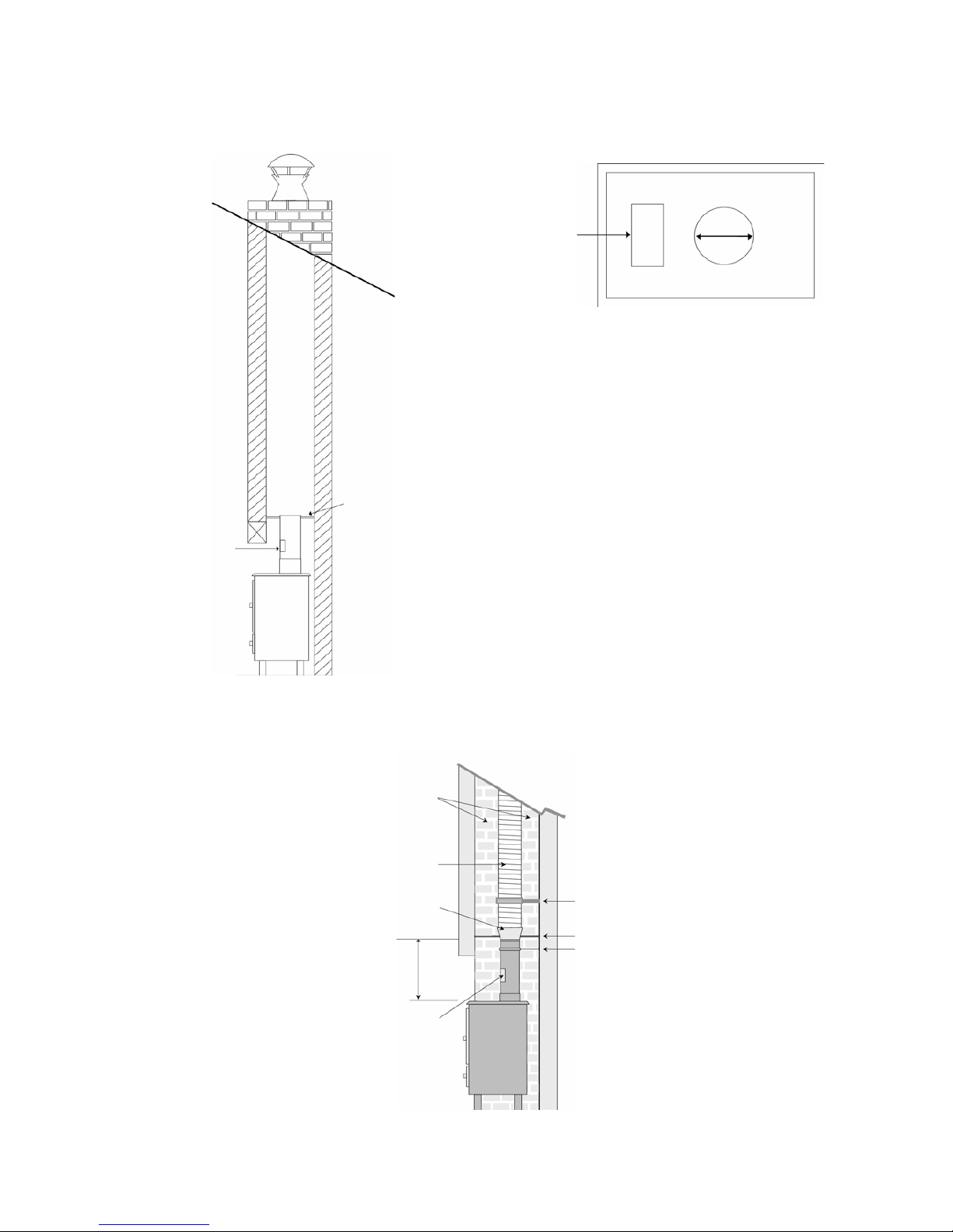
Some typical installations are shown as following
Sealed door to
access chimney for swee
p-
ing & inspec
t-
i
ng.
FLUE
The Flue must be
1.5mm thick rust
resistant steel and 3 times it‘s
diameter away from combustible materials. For example
150mm Flue Pipe must be
450mm away from combustible m
a-
terials.
Access
door
Non-combustible
register plate. Minimum
1.5mm thick rust resistant steel or heat resi
s-
tant board.
TOP FLUE OUTLET
If the chimney is not s
ound, i.e. found to be leaking after a smoke test then the chimney must
either be repaired or a flexible liner may be used, ensure the liner is the correct type for
Multi-Fuel applications. See diagram below:
It is recommended that
this area is insulated or
backf
illed.
Flexible Liner
SW to TW Adapter
Maximum Recommended distance is
1.5mtrs of c
onnecting fluepipe to existing
chimney or Twin Wall Class 1 system
S
upport Bracket for Flexible Liner.
Register Plate
S
upport Bracket for the
c
onnecting fluepipe
Vitreous Fluepipe with
stainless access door.
 Loading...