

Page 1

OTUC-400 Series
SpectrumPlus Upconverter 4x 5-42MHz
INSTRUCTION MANUAL
Phone:
E-Mail: [email protected]
025-000557 REV X1 04/12/07
(209) 586-1022
(800) 545-1022
Fax:
(209) 586-1026
www.olsontech.com
Page 2

TABLE OF CONTENTS
SPECIFICA TIONS Page 3
OPERA TIONAL SETUP Page 4
025-000557 REV X1
Page 2
Page 3

OTUC-400 Series Specifications
RF PERFORMANCE PARAMETERS:
Input Frequency Range (4 Inputs) 5 MHz to 42 MHz
Output Spectrum (stacked) 5 MHz to 206.5 MHz
(Spectrum Inverted on Bands 2,3 & 4) Band 1 - 5 MHz to 42 MHz (non-converted)
Frequency Accuracy Each converted band phase locked to internal 4.5 MHz pilot
Gain (each input to combined output) 15 db +/- 1 dB
Gain Flatness < 3 dB in any band
Noise Figure 14 dB maximum
Maximum Input Signal +15 dBmV/carriers (6 carriers)
Phase Noise > -110dBc Hz @ 10 KHz
Input Return Loss > 15 dB (5 MHz to 42 MHz)
Output Return Loss > 15 dB (5 MHz to 206.5 MHz)
3rd Order I.M. @ +15 dBmV Input/Carrier > 55 dB; typically > 60 dB (6 carriers)
2nd Order I.M. @ +15 dBmV Input/Carrier > 55 dB (6 carriers)
L.O. Rejection Band 2 - 93.5162 MHz > 15 dB
(Measured relative to Input Band 3 - 163.5469 MHz > 15 dB
Carriers @ +15 dBmV/carrier) Band 4 - 211.500 MHz > 15 dB
Image Rejection Band 2 - 98.5 MHz to 133.5 MHz
(55 dB minimum; 60 dB typical) Band 3 - 168.5 MHz to 203.5 MHz
Pilot Output 4.5 MHz @ +25 dBmV
Band 2 - 51.5 MHz to 88.5 MHz
Band 3 - 121.5 MHz to 158.5 MHz
Band 4 - 169.5 MHz to 206.5 MHz
Band 4 - 216,5 MHz to 251.5 MHz
ENVIRONMENTAL PARAMETERS:
Power Requirements Univeral Power, 100-240 VAC @ 16 Watts
Size (Upconverter) 1.25"H x 19"W x 13"D
Operating Temperature Range -40 to +85 degrees C (-40 to +185 degrees F)
025-000557 REV x1
Page 3
Page 4
OPERATIONAL SETUP - RF
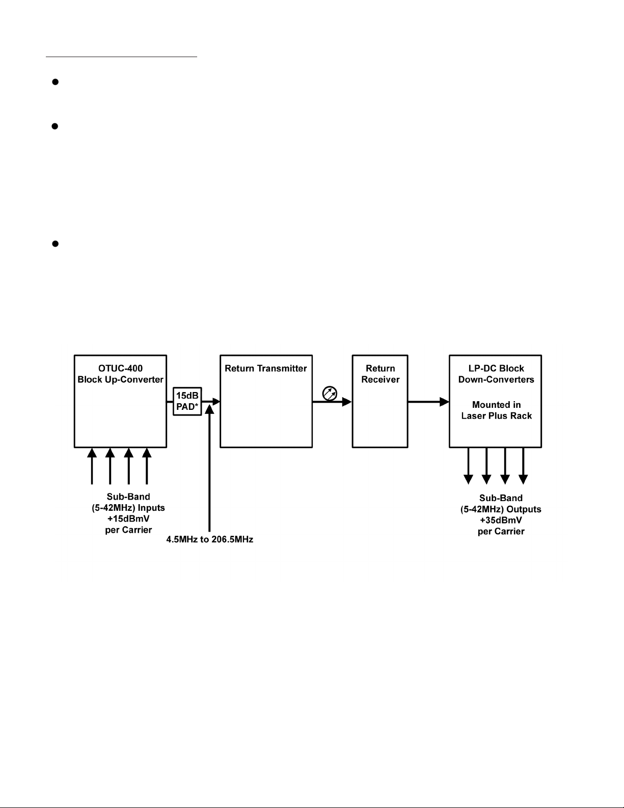
The upconverter accepts four separate return inputs, one from each of the four band input ports. It up-converts
three of them to three different bands, and combines them with one un-converted band. This combination of
four bands plus a pilot carrier at 4.5MHz is fed to the RF Out port on the rear of the unit.
If the OTUC-400 is installed properly , the frequencies of the four bands and their relationship to the four band
input ports are as follows:
BAND ONE 5MHz to 42MHz
BAND TWO 51.5MHz to 88.5MHz
BAND THREE 121.5MHz to 158.5MHz
BAND FOUR 169.5MHz to 206.5MHz
The specification for MAXIMUM carrier level into each converter band is defined as +15dBmV per (CW)
carrier with six carriers present (or 35MHz used). For best return optical system performance, the input level
should be a MINIMUM of +12dBmV per (CW) carrier with six carriers present. The carrier levels may be
adjusted as necessary to provide channel-loading equivalent to the six-carrier levels.
T ypical Operational System Diagram
Ordering Information
OTUC-400 OT “SP” Upconverter; 4X 5-42MHz; 1RU 19" EIA; without 5-300 MHz Upstream Transmitter
OTUC-413 OT “SP” Upconverter; 4X 5-42MHz; 1RU 19" EIA; DFB TX @1310nm; 3 mw; SC/APC
OTUC-415 OT “SP” Upconverter; 4X 5-42MHz; 1RU 19" EIA; DFB TX @1550nm; 2.5 mw; SC/APC
OTUC-447 OT “SP” Upconverter; 4X 5-42MHz; 1RU 19" EIA; CWDM TX @1470nm; 2.5 mW; SC/APC
OTUC-449 OT “SP” Upconverter; 4X 5-42MHz; 1RU 19" EIA; CWDM TX@ 1490nm; 2.5 mW; SC/APC
OTUC-451 OT “SP” Upconverter; 4X 5-42MHz; 1RU 19" EIA; CWDM TX@ 1510nm; 2.5 mW; SC/APC
OTUC-453 OT “SP” Upconverter; 4X 5-42MHz; 1RU 19" EIA; CWDM TX@ 1530nm; 2.5 mW; SC/APC
OTUC-455 OT “SP” Upconverter; 4X 5-42MHz; 1RU 19" EIA; CWDM TX@ 1550nm; 2.5 mW; SC/APC
OTUC-457 OT “SP” Upconverter; 4X 5-42MHz; 1RU 19" EIA; CWDM TX@ 1570nm; 2.5 mW; SC/APC
OTUC-459 OT “SP” Upconverter; 4X 5-42MHz; 1RU 19" EIA; CWDM TX@ 1590nm; 2.5 mW; SC/APC
OTUC-461 OT “SP” Upconverter; 4X 5-42MHz; 1RU 19" EIA; CWDM TX@ 1610nm; 2.5 mW; SC/APC
025-000557 REV x1 Page 4
 Loading...