

Page 1
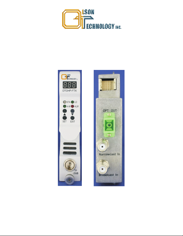
OPTICAL HEADEND PLATFORM
OTOHP-FTX FORWARD PATH 1310nm TRANSMITTER
INSTRUCTION MANUAL
Phone: (209) 586-1022
(800) 545-1022
Fax: (209) 586-1026
E-Mail: [email protected]
OTOHP-FTX Rev. X1 11/16/2010
www.olsontech.com
Page 2

SAFETY WARNINGS
LASER RADIATION
The OTOHP-FTX laser transmitter emits invisible radiation that can cause permanent eye
damage. . Operate the transmitter only with the proper
AVOID DIRECT EXPOSURE TO BEAM
optical fiber installed in the transmitter optical connector.Powertothetransmittershouldbeturnedoff or preferably, disconnected whenever the optical connector cover is opened and there is no
installed fiber (as when the fiber connector is being installed or removed from the transmitter
connector).
NEVER
USE ANY OPTICAL INSTRUMENT TO VIEW THE OUTPUT OF THE LASER
TRANSMITTER. “OPTICALINSTRUMENT”INCLUDESMAGNIFYINGGLASSES,ETC.
NEVER
LOOK INTO THE OUTPUT OF THE LASER TRANSMITTER
NEVER
LOOK INTO THE OUTPUT OF A FIBER CONNECTED TOA LASER
TRANSMITTER.
NEVER
LOOK INTO OR USE ANY OPTICAL INSTRUMENT TO VIEW THE DISTANT END
OF A FIBER THAT MAY BE CONNECTED DIRECTLY OR VIAAN OPTICAL SPLIT, TO A
TRANSMITTER THAT MAY BE OPERATING. THIS SPECIFICALLYAPPLIES TO FIBERS
THATARE TO BE CONNECTED TO RECEIVERS OR OTHER DEVICES ATANY
DISTANCE FROM THE LASER TRANSMITTER.
PRECAUTIONS
Failure to comply with these general safety precautions and with the specific precautions
described elsewhere inthis manualviolates the safety standards of the design, manufacture, and
intended useof thedevice. Olson Technology Inc. assumesno liability forthe customer's failureto
comply with these precautions.
Do not operate the transmitter outside of its ratings. Doing so may result in unsatisfactory
performance, receiver failure, shortened receiver life span, or a safety hazard.
Do not attempt to modify or service any part of a transmitter module. Doing so voids the warranty.
Contact Olson andrequest an RMAnumberandreturntheunitto OlsonTechnology Inc.for service
and repair.
Do not restrict airflow in front of or behind the chassis. The transmitter should be operated in an
ambient environment between 0 and 50ºC (32 and 122ºF).
Store the module awayfrom corrosivematerials,ata temperature between -40 and +70ºC (-40 and
+158ºF), and with no more than 85% humidity,non-condensing.
Page 3
INTRODUCTION
The OTOHP-FTX series is a high performance 1310nm DFB laser transmitter module
that is ideal for broadcast and narrowcast applications in optical transportation. The
modules are available over wide range of optical output power to deliver both analog
and (QAM) CATV digital signals. High performance, advanced pre-distortion circuitry
achieves superior CSO and CTB. All configuration parameters of modules can be
monitored by LED screens on the front panel of the module, or by the OTOHP-NMS
equipment management module. The OTOHP-FTX module can be operated also by
Automatic Gain Control (AGC) or Manual Gain Control (MGC) modes. These modes
can be set uponthefront panel.
OPERATION PANEL DESCRIPTION
14
5
7
9
16
11
17
13
15
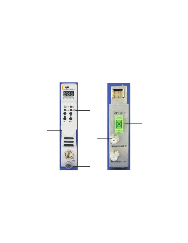
1. Display LED:
1
2 3
4
6
8
10
12
Display the status, AGC & MGC value and alarm code of the
transmitter.
2. STA LED:
Green indicates the module is operating properly. Red indicates the
module has alarms.
3. LD LED:
When green, the OTOHP-FTX module is working under “LD” operation
interface.
4. A-M LED: When green, the OTOHP-FTX module is working under “AGC & MGC”
operation interface.
5. ALM LED: When green, the OTOHP-RRX module is working under “ALM”
operation interface.
Page 4

OPERATION PANEL DESCRIPTION (CONT.)
7. Down:
.
8 Set:
9. Exit:
10 Handle: Used to handlethemodulewhen being installed or uninstalled
11 Heat dissipation hole: Air flow out ofthis hole dissipates the heat.
12 TP:
13 Thumbscrew: Fixes the moduleto thechassis.
14. 30-pin Connector:
15. Optical Output Port: Portforopticaloutput, connector type is SC/APC.
16. Narrowcast In RF Port: Narrowband RF input,connector type is F female.
17. Broadcast In RF Port:Broadband RF input connector type is F female.
1 Inspect for bent pins on the backplane connector at the rear of the module
..
..
2 Gently insert each module into a slot in the front of the chassis Be careful to align
3. Tighten the captive thumbscrew on the frontof the module
Note: If the power supply turns on after the OTOHP-FTX 1310nm optical transmitter is
inserted, the Display LED will flash for 5 seconds, indication the transmitter is selfchecking.
4. Repeat Steps1 through 3 to install the remainingmodules inthe chassis
5. Ensure that the correct RF level is being applied at the associated forward path
..
6 Connect the RF cabling to the appropriate RF IN connector on the rear panel
Push button, selects functionorparametersetting.
Push button, confirm function or parametersetting selection.
Push button, exit certainoperationmode
..
.
Test pointfor RFoutput, F type maleconnector
..
.
typeismale.
Straighten any bent pins before installing the module
the metal guide rails on the top and bottom of the module with the nylon guides in
the interiorof thechassis housing
transmitter CAUTION: Input RF power levels lower than +11dBmV/per channel
can reduce the RFperformanceofthe transmitter module.
Note: The narrowband input level should be 12dB higher than the input level of
broadband. Ensure the frequencies are not the same when both narrowband and
broadband inputs are beingused.
Provides power and signals to the chassis backplane, connector
INSTALLATION
.
.
.
-
,-
.
.
.
Page 5
INSTALLATION (CONT.)
., -(
7 Using a signal level meter measure the RF input at the RF TP test point 20dB
below actual level on the front panel and verify that it is set at the specified value
for that channel Further adjust the RF input level ifrequired
8 Verify that the correct opticalconnector willbe attached to the optical connector on
.
the module Clean both the bulkhead and fiber connectors CAUTION: Using
)
..
..
mismatched optical connectors will damage the connectors and degrade system
performance. Ensure that eachfiberhasa matching connector.
9. Connect the optical fibers to the appropriate OPT OUT connection on the rear
panel Then turnon thelaser from the front panel instructions arebelow
.().
10. Use an optical power meter to verify that the optical output level meets
specifications
.
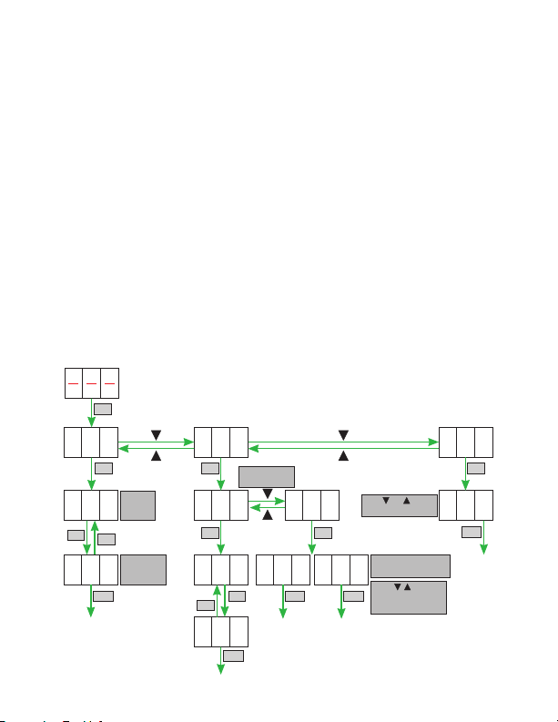
FRONT PANEL NUMERIC DISPLAY OPERATION DESCRIPTION
First pushSET on theLED display and set function.
A01: Laser on/off menu
A02: AGC/MGC setting menu
SET
A03: Alarm menu
A01
SET
FFFF
O
SET
SET
10
4
EXIT
Indicates
Laser
OFF
Indicates
optical
power (dBm)
A02
SET
1 = AGC Mode
2 = MGC Mode
1
SET SET
2
ON FOF
SET
SET
EXIT EXIT
O
EXIT
0
0
Push and to view
the alarm code.
AGC On = Display Off
AGC Off = Display 00
Push , and SET
to set the MGC Value
if AGC = Off
A0003
SET
3
EXIT
Page 6

UNINSTALL THE TRANSMITTER MODULES
DANGER: Laser Radiation—Avoid direct exposure to beam. Inbound laser radiation
associated with this optical output jumper is generated by a Class IIIb laser product.
Disconnected optical connectors might emit invisibleoptical radiation. Laser light, visible
or invisible, can seriously injure eyes and even cause blindness.
1 Disconnect the optical fiber s from the rear panel of the transmitter. Immediately
.()
place protective caps over the bulkhead and fiber connector
2 Disconnect theRF cablesfrom the F connectors
.-.
3. Loosen the thumbscrew on the front panel of the module CAUTION: Do not pull
.
.
on the thumbscrew to remove the module. Pull on the handle that the thumbscrew
goes through to removethemodule.
4. Gently pull the module from the chassis using the handle that the thumbscrew
goes through
.
ALARM DEFINITIONS
First pushSET on theLED display and set function.
Displayed Message
000
001
002
003
004
005
006
007
008
Alarm Status
No alarm
Optical output low
Optical output high
Laser bias high
Laser temperature high
RF input low
Module temperature high
TEC current high
RF input high
System Response
STA LED is green
STA LED turns to red
STA LED turns to red
STA LED turns to red
STA LED turns to red
STA LED turns to red
STA LED turns to red
STA LED turns to red
STA LED turns to red
TROUBLESHOOTING
When the Status light is red the operator can use “ ” “ ” and “SET” push button
,▲,▼
switch to check the alarms. DANGER/CAUTION: Do not remove the cover of the
transmitter or attempt to modify any part of it under any circumstances. Removing the
cover could cause irreparabledamagetothe unit, and will voidyour warranty.
Page 7
Problem
RF input low.
No optical power at the
optical output port.
Optical power is lower than
the required amount.
Loss
Power
Power
0dB 1dB 6dB 7dB 8dB
+3dBm
+6dBm
Loss
7dB 8dB
53 52
+8dBm
+10dBm
+12dBm
+13dBm
TROUBLESHOOTING (CONT.)
Steps to Take
1. Verify RF inputpower is correct.
2. If all is normal, contact Olson Technology Inc. for
further troubleshooting.
1. Clean theconnector.
2. Verify laser functionis set on.
3. Measure the opticalpower atthe output port using
an optical power meter.
4. If there is no optical power at the output port, the
unit must be returned to the factory for service.
Contact Olson Technology Inc. for more
information.
1. Ensure allconnectors are clean.
2. Verify the cable is terminated with the correct
connector type.
3. Measure the opticalpower atthe output port using
an optical power meter.
4. If the optical power is still low, the unit must be
returned to the factory for service. Contact Olson
Technology Inc.for moreinformation.
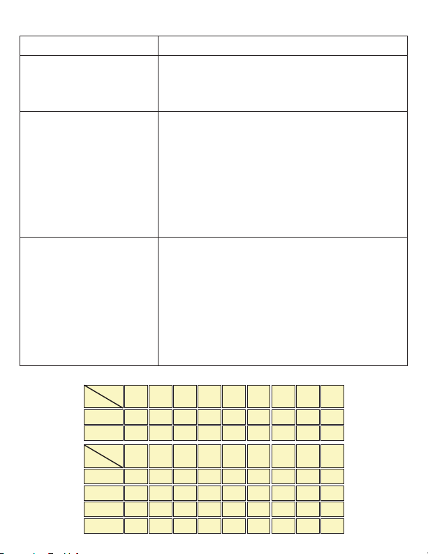
Typical CNR Performance
4dB 5dB2dB 3dB
53 52 51 50
53 52 51 50
9dB 10dB 11dB 12dB 13dB 14dB 15dB
51 50
53 52 51 50
53 52 51 50
53 52 51 50
Page 8
SPECIFICATIONS
Optical Characteristics (with SM 9/125µm Fiber)
Min Typ Max Units
Operating Wavelength 1290 1330 nm
Optical Output Power +3 +13 dBm
Optical Return Loss -55 dB
Optical Output Ports 1
Optical Connector SC/APC
RF Output & Performance Characteristics
Min Typ Max Units
Frequency Range 54 1,000 MHz
Band Flatness -0.75 +0.75 dB
1
RF Input Return Loss 16 dB
RF Input - Broadband +11 +19 dBmV
RF Input - Narrowband +23 +31 dBmV
RF TP - Broadband -21 -20 -19 dB
RF TP - Narrowband -33 -32 -31 dB
Impedance 75 Ohms
CSO -63 dB
2
CTB -67 dB
2
XMOD -65 dB
2
RF Connectors F-female
Electrical & Environmental Characteristics
Min Typ Max Units
Operating Temp. Range 0 +50 °C
Storage Temp. Range -40 +65 °C
Relative Humidity 10 85 %
P. S. Voltage +24 V
3
DC
Power Consumption 12.5 W
NOTES:
1) Band flatness is over a
54-1,000MHz range.
2) 15km fiber + attenuator,
receive power -1dBm,
NTSC 77.
3) Non condensing.
 Loading...