

Page 1
INSTRUCTION MANUAL
OTOT-1000C-FF
WIDE-BAND 1550NM DIRECT-MOD OPTICAL TRANSMITTER
1,000 MHz Bandwidth / Optical Output Power is
+8dBm (OTOT-1000C-08-FF) or +10dBm (OTOT-1000C-10-FF)
Phone: (209) 586-1022
(800) 545-1022
Fax: (209) 586-1026
025-000642 Rev X4
E-Mail: [email protected]
www.olsontech.com
02/01/12
Page 2

SAFETY WARNINGS
LASER RADIATION
The OTOT-1000C-FF laser transmitter emits invisible radiation that can cause
permanent eye damage. . Operate the
transmitter only with the proper optical fiber installed in the transmitter optical connector.
The OTOT-1000C-FF should be turned-off or disconnected whenever the optical
connector coveris opened andthere is no installedfiber (as whenthe fiber connectoris
being installed or removed from the transmitter connector).
NEVER
USE ANY OPTICAL INSTRUMENT TO VIEW THE OUTPUT OF THE
LASER TRANSMITTER. “OPTICAL INSTRUMENT” INCLUDES MAGNIFYING
GLASSES, ETC.
NEVER
LOOK INTO THE OUTPUT OF THE LASER TRANSMITTER
NEVER
LOOK INTO THE OUTPUT OF A FIBER CONNECTED TO A LASER
TRANSMITTER.
NEVER
LOOK INTO OR USE ANY OPTICAL INSTRUMENT TO VIEW THE
DISTANT END OF A FIBER THAT MAY BE CONNECTED DIRECTLY OR VIAAN
OPTICAL SPLIT, TO A TRANSMITTER THAT MAY BE OPERATING. THIS
SPECIFICALLY APPLIES TO FIBERS THAT ARE TO BE CONNECTED TO
RECEIVERS (SUCH AS THE OTPN-400C or OTPN-2000C) OR OTHER
DEVICESATANY DISTANCEFROMTHELASERTRANSMITTER.
HIGH VOLTAGE
parts. There is exposed high voltage inside this unit. Only factory service technicians
should open the unit with power applied.
FIRE HAZARD
connector.Thisfuseis a 250V, 0.5A, 5x20mm,slowblowfuse.Toavoida risk of fire, this
fuse should be replaced only with an identicallyratedfuse.
SHOCK HAZARD
exposure to moisture must be avoided.
- The inside of the OTOT-1000C-FF contains no user serviceable
- The AC line input fuse is contained in the IEC 320 power input
AVOID DIRECT EXPOSURE TO BEAM
- The OTOT-1000C-FF is designed for indoor use only. Direct
Page 3

INTRODUCTION
The OlsonTechnology OTOT-1000-FFisa high performance indoorwideband1550nm
Direct Modulation laser transmitter with an RF passband of48 to 1,000MHz.TheOTOT1000C-FF also offers enhanced CATV performance. These transmitters are intended
for indoor applications. They combine the transmitterand universal AC powersupply in
one compact housing that has a footprint of 7.5" x 5.5" x 1.6". The optical output power
and bandwidth of each transmitter is as follows:
OTOT-1000-08-FF00 +8dBm (6mW)Optical Output
OTOT-1000-10-FF00 +10dBm (10mW)
Optical Output
Where xx = 00 for 1550nm ±10nm.
Each transmitter has a universal power supply that operatesfrom 90 to 240V at 50 or
AC
60 Hz and consumes about 10 Watts. The OTOT-1000C-FF is an ideal forward signal
source forthe OTPN-2000C High SensitivityIndoor Node andallowsfor an opticalpath
loss of 21dB or more without an EDFA. Test points are provided for laser output power
and current to allow for historical review of operating parameters. An RF test point is
provided to allow proper setup and for historical review. SBS suppression is now
available up to +16dBm allowing usage in largePONsystems.
Positive cooling is provided by means of a small, high-MTBF fan, which may be
replaced in the field without interrupting the operationoftheunit.
The OTOT-1000C-FF has flanges on the bottom to allow mounting it to a flat surface.
The available OTLL-RMKIT-1will allow mounting up to three of these unitsinastandard
19" rack.
INSTALLATION/ENVIRONMENTALCONSIDERATIONS
The OTOT-1000C-FF transmitters are specified to operate from -10°C to +55°C.They
usually do not require an air-conditioned environment. They should be mounted in an
adequately ventilated area. Likeall electronic equipment, it will generally havea
longer
life span if it is not operated at the upper limit ofthe temperature range. Installation in wet
areas or areas of extremely high humidity should be avoided. Extremely dirty or dusty
areas should be avoidedif possible. Objects or debris should notbe allowed to block the
openings in the housing or the fan. The unit should not be installed in areas that are
accessible to children.
Page 4
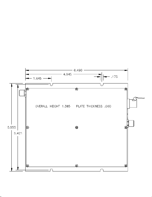
The OTOT-1000C-FF may be installed and operated in any position on a flat surface.
The unit has four slots in the bottom plate to accommodate mounting hardware. If
mounting requires a wood screw, use #6 or #8 (maximum) pan-head sheet metal
screws. These are commonlyavailableathardwarestores.If mounting with a machine
screw (to tapped holes), use 6-32 pan-head screws.
Figure 1 - OTOT-1000C-FF Mounting Diagram
Page 5

OPTICAL CONNECTORS AND CLEANING
The standard optical connectoris an SC/APC. In order to use FC/APCconnectors, you
must order aconversionkit, OTLL-SCFCKIT.The standard optical connector locationis
on the opposite side from the RF connector. The connector can be moved to the other
side by swapping it witha cover plate. Only a screwdriver is required for this operation.
The fiber ends can be damaged by the insertion of contaminated connectors. Some
types of customer damage to connectors are not covered under warranty. Fiber
connectors should never be left uncovered. Pre-packaged alcohol wipes are the most
convenient means of cleaning optical connectors. Clean alcohol and lint free wipes,
such as Kim-Wipe type 34155, or swabs may also be used.
connectors with optical power present!
connectors with optical power present!
NEVER clean optical
NEVER clean optical
INTERNAL CONTROLS
There are no internal user adjustments. The only reason to open the unit would be to
move the fiberconnectortotheother end of the unit. This shouldbedonebeforethe unit
is attached to a rackmount kit.The unitshould not be operated for long periods of time
without a top cover. This can cause RF radiation and ingress problems. The internal
cooling is also reduced when uncovered. Be sure to replace and tighten all top cover
screws. Oscillation or RF radiation can be caused by loose or missing screws. Thereis
no user adjustable internal laser power adjustment. Any change to the laser power will
result in poorer modulation characteristics and reduced link performance.
DISTANCE LIMITATION
Most fiber optic transmitters are attenuation limited. In other words, the amount of
optical powerthat reaches the optical receiver is usually theonly factor thatdetermines
the CATV performance. Directly-modulated 1550nm transmitters, such as the OTOT1000C-FF, also have a distance limitation. The OTOT-1000C-FF will offer the best
performances at short fiber distances. As the fiber distance increases, the CSO will
generally degrade. The maximum specified operating distance forthe OTOT-1000C-FF
with standard SMF-28 fiber is 10km.This increases to 25km with NZ-DSF fiber. At that
distance, the CSO will be at its worst, -53dBc. This type of transmitter is usually used
with an EDFAwith launch powersup to+16dBm per fiber and optical splitters to drive a
large number of receivers, at transmitter-to-receiver distances of 10km or less with
standard SMF-28 fiber.
Page 6

EXTERNAL CONTROLS AND TEST POINTS
There are twoexternalDCtestpoints. One reads laser currentat1Vper50mA.A typical
laser current of 30mA would read 0.6V at this test point. The laser power test point is
0.1V per mW. This is for historical tracking. The optical power meter is a much more
accurate means ofmeasuringpower. Both of thesetestpointsshouldbe measured with
a highimpedancevoltmeter. There isanexternal multi-turn RF input attenuationcontrol
on the front panel. This is set at the factory to the fully clockwise position which yields
minimum attenuation. The user can add 4dB of attenuation with this control which
allows the input RF level tobe up to 4dB higher than therecommended levels. There is
also
an external 75ΩRFtestpoint.Thistestpoint measures the laser drive level,notthe
RF input level. This test point has been adjusted to read a very specific level when the
RF drivehas been adjusted foroptimum optical modulation.Forthe factory testedinput
loading of 77 analog and 42 digital channels, this test point should read +10dBmV at
547.25MHz with the RF gain control pot is fully clockwise. At this frequency, the loss in
the connecting cableandanyimpedancematching devices can be verysignificant.See
the section on input loading for the propertestpointlevelswithotherinputconditions.
INITIAL SETUP
Mount the unit and apply power. The laser is temperature controlled. The unit will
operate immediately after turn on, but requires about 5 minutes to temperature stabilize.
Measure and record the optical output with a power meter. Measure and record the
laser current andopticalpower readings at the externaltestpoints.Measure and record
the RF input levels. At this frequency range the loss and slope of coax
CAUTION:
cables is very significant. The best approach is to connect the cable that will go to the
OTOT-1000 input directlytothe measurement device. Theinputsignals should be
flat within ±1dB, preferably within ±0.5dB. worse than this will result in
degrad NR
C-FF
Flatness
ed C and or distortion performance.
Special attention must be paid to the relative level of the channel that is used to set the
RF gain and thus set the laser modulation. If thischannel ismuch higher than the other
channels, then setting the RF gain will cause the other channels to be lower than
optimum, resultingin reduced CNR performance. Ifthis channel istoo low, then usingit
to set the RF gain will cause the other channels to be higher than optimum, resulting in
reduced distortion performance. A 1 to 2dB error will cause significantly impaired
dB
performance. Connect the RF input tothe unit and adjust the RF gaincontrol for a level
Page 7

that indicates proper modulation. For the factory test condition, this is +10dBmV at
547.25MHz. For other channel loadings, consult the next section. Do not forget to
account for the loss in the connecting cable.
INPUT DRIVE vs. CHANNEL LOADING
The laser RF drive level is the primary determining factor of link distortion and CNR
performance. Thebasic limitation oninput drive istotal input power. Figure 2shows the
approximate input levels versus channel loading. The left axis shows the nominal RF
input level. The unit will work with levels within ±2dB of this value. The right axis shows
the test point reading for optimum modulation. Most systems run their digital channels at
6dB below the analog channels. This is a very convenient level for calculating loading.
At 6dB down,simplydividethenumber of digital channels by 4andaddtothenumber of
analog channels to get the total equivalent analog channel loading. The factory test
input is 77 analog channels with 42 digital channels at 6dB down. The number of
equivalent analog channels is 77 + 42/4, which equals 87.5. This is the 87.5 ch /
+18.6dBmV input point on the graph. Some systems use an OMI meter to set laser
modulation. The OTOT-1000C-FF’s have been individually adjusted for optimum
performance. Setting all units for the same OMI, instead of using the test point, will result
in reduced transmitter performance. If the channel loading is less than 40, you may
decide not to increase the levels by the maximum possible amount. This will provide
improved distortion at the cost of CNR. The best rule of thumb is to use the maximum
possible levels for long haul links, and lowerdrivelevelsasthelinksgetshorter.
REDUCING LINK GAIN
Short links can have reduced performance due to receiver overloading. Reducing the
laser RF drive will cause reduced CNR performance. Attempting to lower the laser
output power will have the even worse result of degrading both CNR and IMD. The
correct solutionis to lowerthe receiver inputlevel with anoptical attenuator suchas the
OTOA-1000. It isrecommendedthatthisbedoneatthereceivelocation.
Page 8
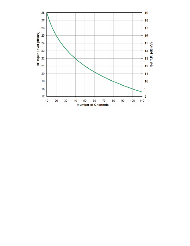
Figure 2 - Input Level vs. Channel Loading
ACCESSORIES
MODEL DESCRIPTION
OTLL-SCFCKIT Optical ConnectorAdapterKit,SC/APCtoFC/APC
OTLL-RMKIT-1 Rack MountKit (Holds3OTOT-1000C’s)
OTOA-1000 Optical FiberAttenuator, 1310nm, 1-7dBVariable Steps
OTLL-FANKIT Replacement FanAssembly
RELATED OLSON TECHNOLOGY PRODUCTS
MODEL DESCRIPTION
OTPN-800C Wideband (50-1,000MHz) Medium-Power Indoor Node
OTPN-2000C Wideband (50-1,000MHz) High-Power Indoor Node
OTPN-2000C-PAL Wideband (85-1,000MHz)High-PowerIndoorNode
 Loading...