

Page 1

LCM-300-S
FREQUENCY AGILE
SUB-BAND TELEVISION MODULATOR
INSTRUCTION MANUAL
Phone:
E-Mail: [email protected]
025-370308 REV B 8/22/01
(209) 586-1022
(800) 545-1022
Fax:
(209) 586-1026
www.olsontech.com
Page 2

LCM-300-S
Specifications
Output Frequency Range.........................
F .C.C. Offset..........................................
Output Power Level................................
Frequency Accuracy / Stability .................
V ideo Performance.................................
Spurious Outputs....................................
Out-of-Band C/N...................................
In-Band C/N..........................................
Audio / V ideo Ratio................................
Channel T -7 (7MHz) through Channel W (300MHz).
Selectable by front panel DIP switch in 2MHz
increments (250KHz internal adjustment)
+12.5KHz tunable by front panel adjustment
+45dBmV typical, +40dBmV minimum per channel
<±5KHz of selected channel frequency
1V P-P input nominal for 87% modulation.
Differential gain <5% Differential Phase <5°
>60dB typical, >55dB minimum below output visual
carrier level
>76dB as measured in a 4.0MHz noise bandwidth
>60dB as measured in a 4.0MHz noise bandwidth
Adjustable from 13dB to20dB below video carrier
Audio Performance.................................
Audio Intercarrier Stability .......................
BTSC Stereo / Mono..............................
Front Panel Controls...............................
Rear Panel Connectors............................
Power Requirements...............................
Chassis Size............................................
500mV P-P for 25KHz deviation, front panel adjustable. 10K input Z
4.5MHz within ±1KHz
Internal defeat of audio pre-emphasis for BTSC
baseband inputs. Shipped mono mode
RF output adjust
A/V ratio adjust
V ideo & Audio modulation
F .C.C. offset adjust
Channel select DIP switches
RCA type video/audio input
T ype F RF output
5V @ 100mA, 10V @ 370mA and 24V @ 3mA
7”D x 1.125”W x 1.75”H
025-370308 REV B
Page 2
Page 3

1.) INTRODUCTION
The Olson T echnology LCM-300-S is a sub-band frequency agile F .C.C. compatible modulator in a 7”D x
1 1/8”W x 1 3/4”H desktop chassis. The LCM-300-S may be operated at 45dBmV typical, +40dBmV
guaranteed minimum. No IF loops are provided on this modulator .
The LCM-300-S modulator will operate on any sub-band, standard, or cable channel from 5MHz –
300MHz. All channels are selectable by front panel DIP switches and a front panel adjustment allows setting
to F .C.C. offset frequencies, HRC frequencies are available.
The LCM-300-S is designed to be operated in the LCM-550-RKA rack assembly .
Note: The LCM-300-S is shipped with channel T7 selected.
The LCM-300-S offers the unique Olson T echnology feature of >76dB out-of-band C/N ratio. SA W
filtering is used for adjacent channel operation and provides 55dB of spurious free dynamic range.
LCM-300-S
Sub-band Frequency Agile –T elevision Modulator
The LCM-300-S has low power consumption for economical and reliable long-term operation.
025-370308 REV B
Page 3
Page 4
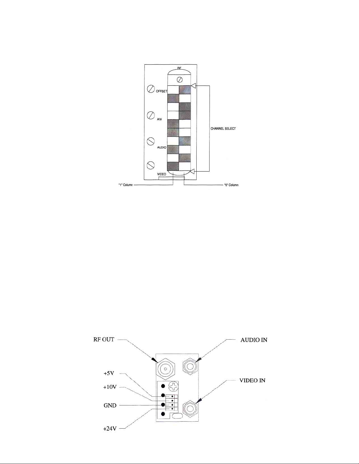
2.) CHANNEL SELECTION
Channel frequencies are selected by setting the 10-position DIP switch (visible through the vertical slot in the
front panel). The front panel is illustrated in figure 1.
Figure 1 – LCM-300-S Front Panel
Switch-setting codes for sub-band channels are shown in T able 1. Switch-setting codes for standard
channel frequencies can be found in T able 2 in this manual, HRC code settings are shown on T able 3. The
front panel illustration in Figure 1 shows a switch properly set for sub-band channel T7.
3.) F .C.C. OFFSET ADJUSTMENT
F .C.C. Offset frequencies are shown in T able 4. T o adjust the frequency of a selected channel to provide
the correct F .C.C. offset, look up its offset frequency in T able 4. Remove the video input and connect a
counter to the RF output of the LCM-300-S. Use the front panel offset adjust control to set the output
frequency to the correct value.
4.) REAR P ANEL
The rear panel of each module has its audio and video inputs and its RF output.
The audio and video inputs are RCA type phono jacks and the RF output is a type “F”.
025-370308 REV B
Page 4
Page 5

5.) VIDEO MODULA TION ADJUSTMENT (Each modulator).
LCM-300-S modulator modules are preset at the factory for 85% depth of modulation with a 1V P-P pulse
and bar test signal. If the video modulation needs to be adjusted, follow the procedure below .
Connect the video source (to be used at approximately 1V P-P) to the video input
phono jack. The video should be of a reasonably bright scene (commercials are
usually excellent).
Adjust the video modulation control on the front panel to obtain approximately 85% depth-of modulation as
measured on a spectrum analyzer or other test equipment capable of this measurement.
If the video modulation control needs to be set and there is no test equipment available, it can be set fairly
close by comparison. V iew a video signal on a properly adjusted television receiver or receiver/monitor.
Apply the same signal if possible, or one of equivalent brightness and contrast to the modulator that needs to
be set. V iew the output of this modulator on the same receiver and adjust the video modulation control for
brightness and contrast equivalent to the directly viewed picture. Use caution and do not set this control too
high.
6.) AUDIO MODULATION ADJUSTMENT (Each modulator).
Connect the audio source (to be used at approximately 500mV P-P) to the audio input phono jack.
Monitor the audio on a television receiver and adjust the audio modulation control for proper loudness as
compared with some channel known to be modulating at the correct level (such as a broadcast station).
The two sources of audio should be very similar in their content and should be near maximum loudness as
compared to the average level of their program. In other words, compare a loud passage with a loud
passage and set the audio modulation control with this program material. Use caution and do not set this
control too high.
7.) OPERA TION WITH COMPOSITE BASEBAND BTSC AUDIO INPUT
The LCM-300-S modulators are compatible with a composite baseband BTSC audio input. An internal
jumper must be changed to remove audio pre-emphasis as required for this application.
T o remove audio pre-emphasis, remove cover screws (top, sides, and front), disconnect and remove the
LCM-300-S module from the chassis and remove its left side cover. Locate the small trace to the rear of,
and slightly above U16, which runs up and down just to the rear of C116. Note that this trace is connected
to the rear side of C116. Cut this vertical trace.
Replace the module cover, replace the module in the chassis, and set the audio deviation per the instructions
for the BTSC generator being used.
025-370308 REV B
Page 5
Page 6

8.) RF OUTPUT AND AURAL CARRIER LEVEL ADJUSTMENT (Each modulator)
A) Using a field strength meter or spectrum analyzer, set the video carrier to the desired level with the
output level (RF) control (typically +40 to +45dBmV).
B) Tune the field strength meter to the aural carrier, which is located 4.5MHz above the video carrier .
C) Adjust the aural carrier level control (A\V) to the desired level, typically 15dB below the video
carrier. CAUTION: Reducing the aural \ visual carrier ratio to less than 15dB can result in high outof-band spurious signals on adjacent channels.
9.) MISCELLANEOUS
A) The front panel adjustments (RF , OFFSET , etc.) are small, and somewhat delicate. Use CAUTION
and an adjustment tool that is a proper fit when adjusting these controls.
B) The LCM-300-S is BTSC stereo compatible. Each modulator is shipped in the “mono” mode.
T o defeat the pre-emphasis in order to use a composite baseband BTSC input signal, see section 7
of this manual.
025-370308 REV B
Page 6
Page 7
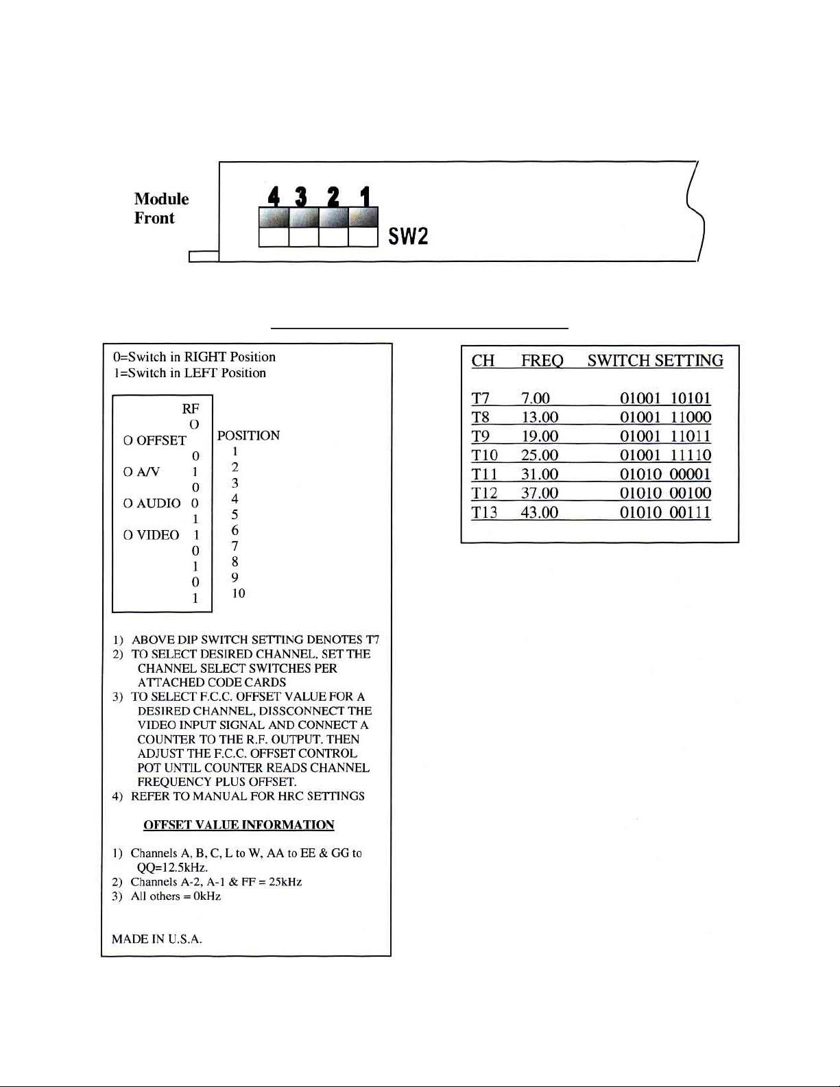
For SUB-BAND operation internal switch SW2 must be set as illustrated below .
(Shipped from factory in Sub-Band mode)
Right Side – Cover Removed
(Internal Module)
Sub-band Setting
Front Panel Dip Switch Settings (Sub-Band)
025-370308 REV B
T able 1 - SUB-BAND SWITCH SETTING CODES
Page 7
Page 8
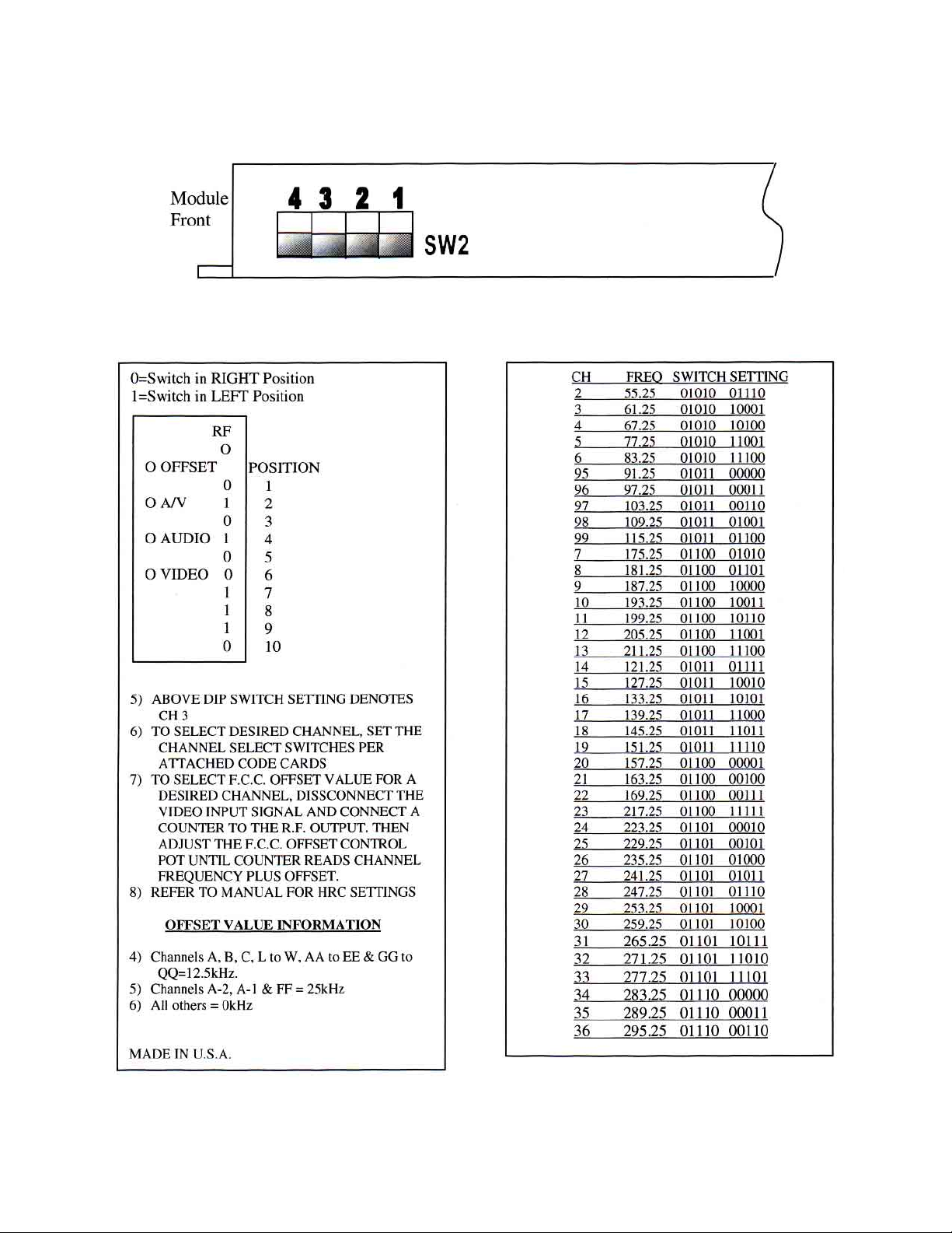
Standard channel switch settings
Right Side – Cover Removed
(Internal Module)
Standard Setting
025-370308 REV B
T able 2 - ST ANDARD SWITCH SETTING CODES
Page 8
Page 9
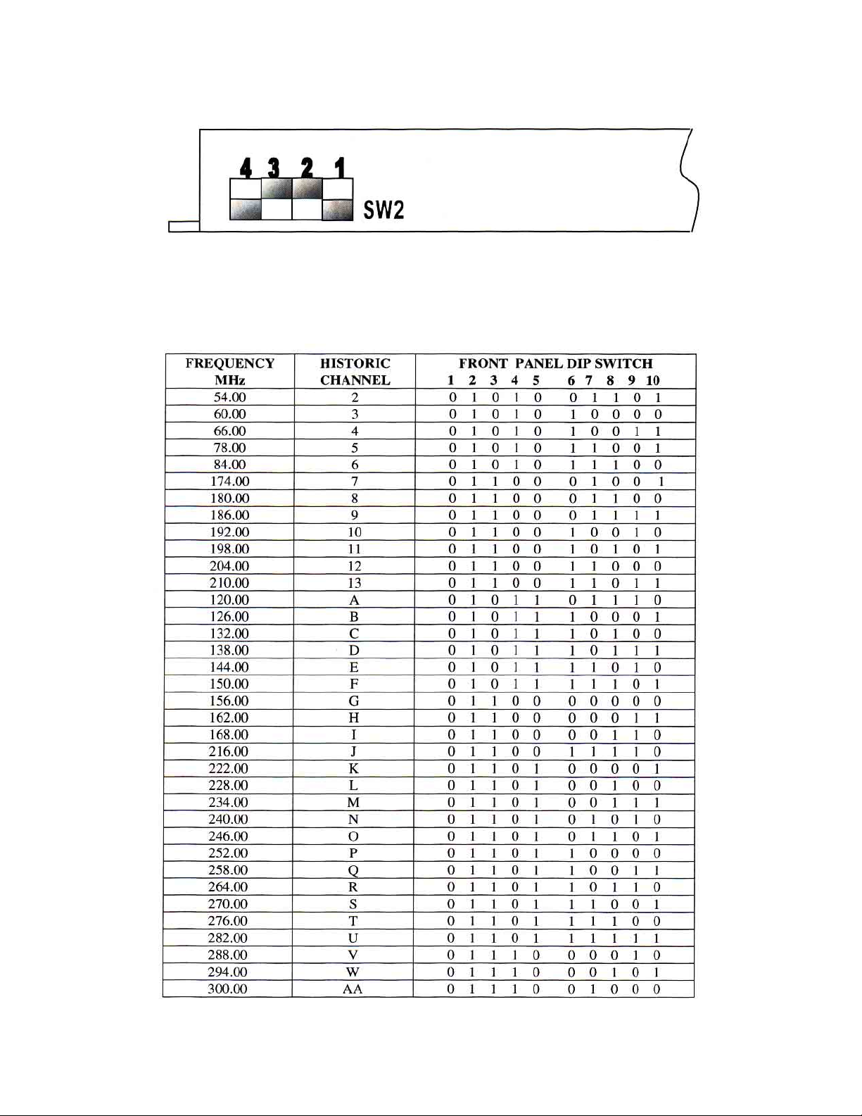
Right Side – Cover Removed
(Internal Switch)
HRC Setting
HRC CHANNEL CODES
025-370308 REV B
Page 9
Page 10
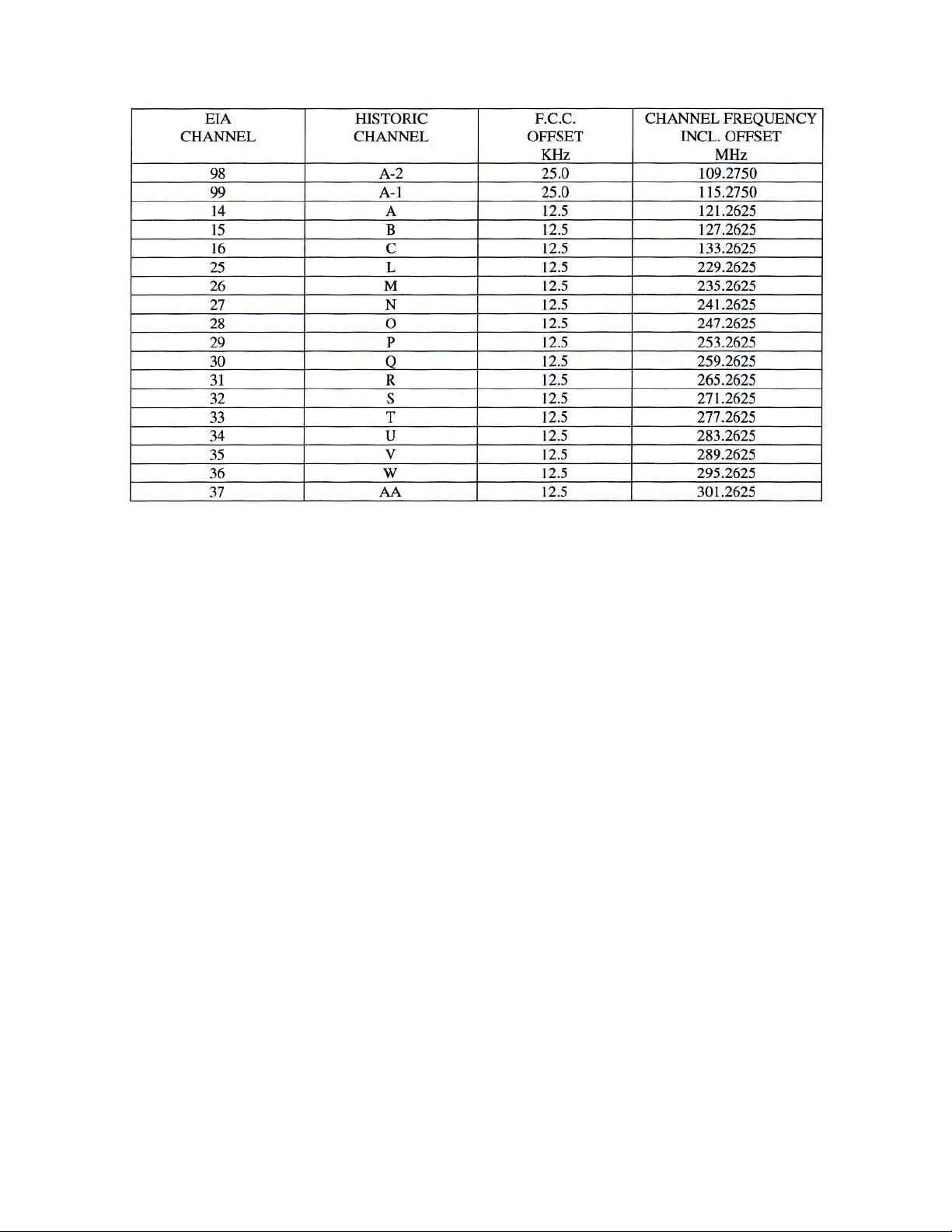
F .C.C. OFFSET FREQUENCIES
T able 4 - F .C.C. OFFSETS
025-370308 REV B
Page 10
 Loading...