

Page 1
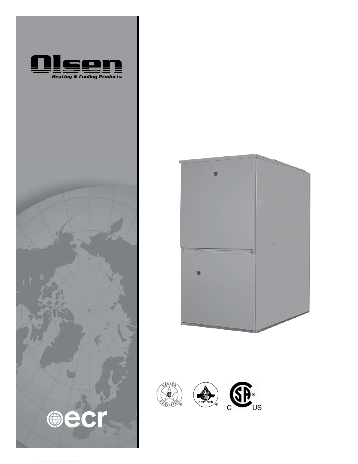
G95V
NATURAL AND PROPANE GAS TWO
STAGE HIGH EFFICIENCY (CONDENSING)
WARM AIR FURNACE
INSTALLATION, OPERATION &
MAINTENANCE MANUAL
An ISO 9001-2008 Certified Company
Manufacturedby:
ECRInternational,Inc.
2201 Dwyer Avenue, Utica NY 13501
web site: www.ecrinternational.com
P/N 240006743, Rev. E [04/2012]
Page 2

TABLE OF CONTENTS
1-WarningsAndSafetySymbols..........................................................................................................................3
2-FurnaceDimensionsAndClearanceToCombustibles....................................................................................6
3-InstallationRequirements................................................................................................................................7
4-FurnaceSizing....................................................................................................................................................9
5-LocationOfUnit...............................................................................................................................................10
6-CombustibleClearances.................................................................................................................................12
7-DuctWork.........................................................................................................................................................12
8-VentilationAndCombustionAir.....................................................................................................................13
9-VentingAndCombustionAirPiping..............................................................................................................14
10-Non-DirectVentFurnaceInstallations(UsingIndoorCombustionAir)....................................................15
11-DeterminingCombustionAir........................................................................................................................15
12-VentingGuidelines........................................................................................................................................18
13-Terminations..................................................................................................................................................22
14-VentClearances.............................................................................................................................................26
15-VentAndDrainingOptions-Upflow............................................................................................................29
16-CondensateDrains........................................................................................................................................33
17-GasSupplyAndPiping..................................................................................................................................34
18-Conversions....................................................................................................................................................36
19-ElectricalSpecifications.................................................................................................................................39
20-LowVoltageWiring.......................................................................................................................................41
21-OptionalAccessories(FieldSupplied/Installed)..........................................................................................42
22-StartupProcedures........................................................................................................................................42
23-AirFlow...........................................................................................................................................................44
24-MaintenanceAndTroubleshooting.............................................................................................................47
25-TroubleshootingFlowchart..........................................................................................................................50
26-DiagnosticCodesForStatusLed..................................................................................................................51
27-WireDiagramForTwoStageFurnaceWithECM.........................................................................................53
28-VentingChecklist...........................................................................................................................................54
29-ReplacementPartsList..................................................................................................................................55
PLEASE READ THIS MANUAL CAREFULLY AND KEEP IN A SAFE PLACE FOR FUTURE REFERENCE BY A
SERVICE TECHNICIAN.
2
Page 3
G95V WARM AIR FURNACE
Introduction
is 95% e cient gas red two stage condensing furnace is an
up ow, down ow, horizontal le and right warm air furnace suitable for residential and light commercial heating applications from
60,000 to 120,000 BTU/Hr.
e 95% e cient furnace series is CSA design certi ed as a Category
IV indirect or direct vent central forced air furnace. When installed
as a direct vent furnace, all combustion air is supplied to the furnace
burners through the air intake system. (See Section 8, “Ventilation
and Combustion Air.”)
All models may be red by natural gas or LP gas (propane) and may
be eld converted from natural gas to LP gas.
e furnace is shipped completely assembled except for the drain
trap assembly and the venting. Please inspect for damage when the
furnace is unpacked.
IMPORTANT: Read the following instructions COMPLETELY before installing!!
1 WARNINGS AND SAFETY SYMBOLS
e following de ned symbols are used throughout this manual to
notify the reader of potential hazards of varying risk levels.
DANGER
Indicates an imminently hazardous situation which, if not
!
avoided, WILL result in death, serious injury or substantial
property damage.
WARNING
Indicates an imminently hazardous situation which, if not
!
avoided, may result in death, serious injury or substantial
property damage.
CAUTION
!
Indicates an imminently hazardous situation which, if not
avoided, may result in injury or property damage.
NOTICE
Indicates information which should be followed to ensure
proper installation and operation.
3
Page 4
1 WARNINGS AND SAFETY SYMBOLS
WARNING
If the information in these instructions is not followed
!
exactly, a re or explosion may result, causing property
damage, personal injury or loss of life.
WARNING
is product must be installed by a licensed plumber or
!
gas tter when installed within the commonwealth of massachusetts.
WARNING
ese instructions are intended as an aid to quali ed service personnel for proper installation, adjustment and operation of this furnace. Read these instructions thoroughly
!
before attempting installation or operation. Failure to follow these instructions may result in improper installation,
adjustment, service or maintenance, possibly resulting in
re, electrical shock, carbon monoxide poisoning, explosion, property damage, personal injury or death.
WARNING
FOR YOUR SAFETY
Do not store or use gasoline or other ammable vapors
and liquids, or other combustible materials in the vicinity
of this or any other appliance.
WHAT TO DO IF YOU SMELL GAS
Do not try to light any appliance.
Do not touch any electrical switch; do not use any phone
in your building.
Immediately call your gas supplier from a neighbor’s
phone, or a cellular phone from a location well away from
!
the building. Follow the gas supplier’s instructions.
If you cannot reach your gas supplier, call the re department.
Do not re-enter the building until authorized to do so by
the gas supplier or the re department.
Improper installation, adjustment, alteration, service or
maintenance can cause injury, property damage or loss of
life. Refer to this manual.
Safety Rules
1.
Use this furnace only with type of gas approved for this furnace.
Refer to the furnace rating plate.
2.
Install this furnace only in dry indoor locations (protected from
weather).
3.
Provide adequate combustion and ventilation air to the furnace
space as speci ed in Section 8 of this manual, “Ventilation and
Combustion Air.”
4.
Combustion products must be discharged outdoors. Connect
this furnace to an approved vent system only, as speci ed in
Section 9 of this manual, “Venting and Combustion Air Piping.”
5.
Never test for gas leaks with an open ame. Use a commercially
available soap solution made speci cally for the detection of
leaks to check all connections as speci ed in Section 17 of this
manual, “Gas Supply and Piping.”
Installation and service must be performed by a quali ed
installer, service agency or the gas supplier.
6.
Always install furnace to operate within the furnace’s intended
temperature-rise range with a duct system, which has an external static pressure within the allowable range, as speci ed in
Sections 4, 7, and 23 of this manual, “Furnace Sizing,” “Ductwork,” and “Air ow.”
7.
When a furnace is installed so that the supply ducts carry air
circulated by the furnace to areas outside the space containing
the furnace, the return air shall also be handled by duct(s) sealed
to the furnace casing and terminating outside the space containing the furnace. (Furnace for heating the home located in the
attached garage, for example).
8.
A gas- red furnace for installation in a residential garage must
be installed so that the burners and ignitor are no less than 18”
above the oor. e furnace must be located, or protected to
avoid physical damage by vehicles. (See safety warning).
9.
is furnace is not be used for temporary heating for buildings
under construction.
4
Page 5
1 WARNINGS AND SAFETY SYMBOLS
Codes
1.
is furnace must be installed:
A. In accordance with all local codes, by-laws and regulations
by those authorities having jurisdiction.
B. In Canada, this furnace must be installed in accordance
with the current CAN/CGA -B149 Installation Code for
Natural Gas and Propane Installations.
C. In the United States, this furnace must be installed in
accordance with the current ANSI Z223.1 (NFPA 54) National Fuel Gas Code.
2.
Electrical connections must be made in accordance with:
A. Any applicable local codes, by-laws and regulations.
B. Canada: current edition of CAN/CSA C22.1, Canadian
Electrical Code (Part 1).
C. United States: current edition of ANSI/NFPA 70, National
Electrical Code.
Codes and additional information may be obtained from:
Canadian Standards Association
5060 Spectrum Way
Mississauga, Ontario, L4W 5N6
Phone: (416) 747-4000
American Gas Association
400 North Capitol Street, NW, Suite 450
Washington DC, 20001
Phone: (202) 824-7000
National Fire Protection Association
1 Batterymarch Park
Quincy, MA, 02169-7471
Phone: (617) 770-3000
!
WARNING
Do not install this furnace in a mobile home! is furnace
!
is not approved for installation in a mobile home. Doing so
could cause re, property damage, personal injury or loss
of life.
WARNING
THE FURNACE CONTAINS FOIL COVERED FIBER-
!
GLASS INSULATION. Inhalation of berglass particles is
associated with respiratory disease including cancer.
WARNING
Natural gas and propane are normally odorized by the fuel
supplier. In some cases, the odorant may not be perceiv-
!
able. Installation of UL and ULC recognized fuel gas
detectors installed in accordance with their manufacturer’s
instructions is recommended as an additional margin of
safety.
WARNING
e exhaust gases from this furnace contain chemicals
which on some occasions may include carbon monoxide
(CO). Carbon monoxide is an odorless, tasteless, clear colorless gas which is highly toxic. Even low concentrations
are suspected of causing birth defects and other reproduc-
!
tive harm.
UL and ULC recognized CO detectors are recommended
for all buildings equipped with fossil fuel burning appliances. All CO detectors should be installed in accordance
with their manufacturer’s instructions and applicable local
building codes.
WARNING
When this furnace is installed in a residential garage, it
must be installed so the burners and ignition source are
located no less than 18” above the oor to prevent the risk
of igniting ammable vapors which may be present in the
!
garage.
e furnace must be located or protected to avoid physical
damage by vehicles.
Failure to heed these warnings can cause a re or explosion, resulting in property damage, personal injury or loss
of life.
5
Page 6
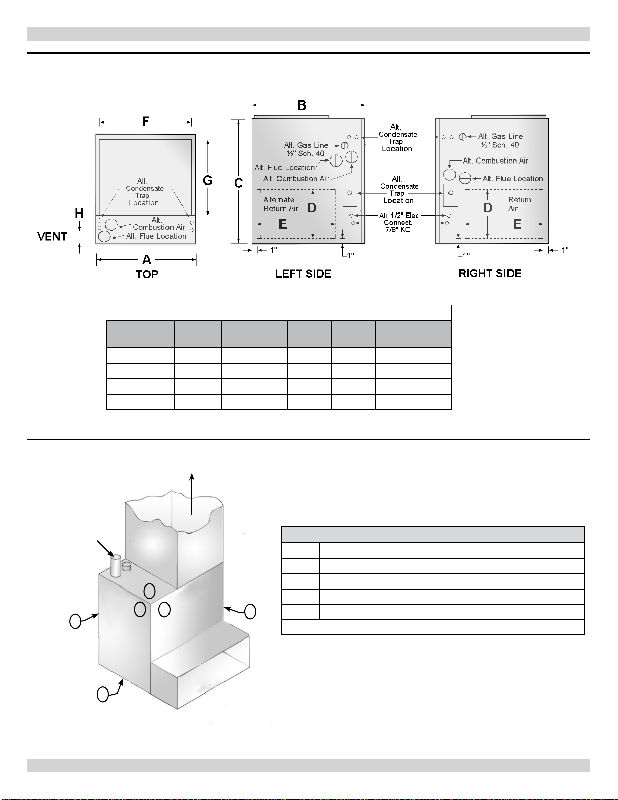
2 FURNACE DIMENSIONS AND CLEARANCE TO COMBUSTIBLES
Figure 1 - Furnace Dimensions
TABLE 1 - FURNACE DIMENSIONS
Model Width A Depth B
60 16⅞” 29” 40” 2” 15⅞” x 20”
80 18½” 29” 40” 2” 17½” x 20”
100 20½” 29” 40” 2” 19½” x 20”
120 23½” 29” 40” 2” 22½” x 20”
Height
C
Vent H
Supply Air
(F x G)
Figure 2 - Clearance To Combustibles
AIRFLOW
VENT
A
B
C
C
FRONT
D
D
SIDES
FILTER
Table 2 - FURNACE CLEARANCE TO COMBUSTIBLES
SIDE Distance
A 1" or Non-Combustible Floor
B 0", Service Clearance 24” or more
C0"
C
D Combustible Floor (must not be placed on carpet non-ceramic tile)
All models are approved for closet installation
For downfl ow installations use optional sub-
base kit 550001346
6
Page 7

3 INSTALLATION REQUIREMENTS
Installation Requirements Speci c To The State Of
Massachusetts For Direct Vent, Mechanical Vent, And
Domestic Hot Water Appliances.
For all side wall horizontally vented gas fueled equipment installed
in every dwelling, building or structure used in whole or in part
for residential purposes, including those owned or operated by the
commonwealth and where the side wall exhaust vent termination
is less than seven feet above nished grade in the area of the venting, including but not limited to decks and porches, the following
requirements shall be satis ed:
1.
INSTALLATION OF CARBON MONOXIDE DETECTORS:
At the time of installation of the side wall horizontal vented
gas fueled equipment, the installing plumber or gas tter shall
observe that a hard wired carbon monoxide detector with an
alarm and battery back-up is installed on the oor level where
the gas equipment is to be installed. In addition, the installing
plumber or gas tter shall observe that a battery operated or
hard wired carbon monoxide detector with an alarm is installed
on each additional level of the dwelling, building or structure
served by the side wall horizontal vented gas fueled equipment.
It shall be the responsibility of the property owner to secure the
services of quali ed licensed professionals for the installation of
hard wired carbon monoxide detectors.
4.
INSPECTION: e state or local gas inspector of the side wall
horizontally vented gas fueled equipment shall not approve
the installation unless, upon inspection, the inspector observes
carbon monoxide detectors and signage installed in accordance
with the provisions of 248 CMR 5.0(2)(a)1. through 4.
5.
EXEMPTIONS: e following equipment is exempt from 248
CMR 5.08(2)(a)1. through 4.:
A. e equipment listed in Chapter 10 entitled “Equipment
Not Required To Be Vented” in the most current edition of
NFPA54 as adopted by the Board; and
B. Product Approved side wall horizontally vented gas fueled
equipment installed in a room or structure separate from
the dwelling, building or structure used in whole or in part
for residential purposes.
6.
MANUFACTURER REQUIREMENTS A. GAS EQUIPMENT VENTING SYSTEM PROVIDED.
When the manufacturer of Product Approved side wall
horizontally vented gas equipment provides a venting
system design or venting system components with the
equipment, the instructions provided by the manufacturer
for installation of the equipment and the venting system
shall include:
A. In the event that the side wall horizontally vented gas
fueled equipment is installed in a crawl space or an attic,
the hard wired carbon monoxide detector with alarm and
battery back-up may be installed on the next adjacent oor
level.
B. In the event that the requirements of this subdivision can
not be met at the time of completion of installation, the
owner shall have a period of thirty (30) days to comply
with the above requirements; provided, however that during said thirty (30) day period, a battery operated carbon
monoxide detector with an alarm shall be installed.
2.
APPROVED CARBON MONOXIDE DETECTORS: Each
carbon monoxide detector as required in accordance with the
above provisions shall comply with NFPA 720 and be ANS/UL
2034 listed and IAS certi ed.
3.
SIGNAGE: A metal or plastic identi cation plate shall be permanently mounted to the exterior of the building at a minimum
height of eight (8) feet above grade directly in line with the
exhaust vent terminal for the horizontally vented gas fueled
heating appliance or equipment. e sign shall read, in print
size no less than one-half )1/2) inch in size.
“GAS VENT DIRECTLY BELOW. KEEP CLEAR OF ALL OBSTRUCTIONS”.
• Detailed instructions for the installation of the venting
system design or the venting system components; and
• A complete parts list for the venting system design or
venting system.
B. GAS EQUIPMENT VENTING SYSTEM NOT PROVID-
ED. When the manufacturer of a Product Approved side
wall horizontally vented gas fueled equipment does not
provide the parts for venting the ue gases, but Identi es
“special venting systems”, the following requirements shall
be satis ed by the manufacturer:
• e referenced “special venting system” instructions
shall be included with the appliance or equipment
installation instructions; and
• e “special venting systems” shall be Product Approved by the Board, and the instructions for that
system shall include a parts list and detailed installation
instructions.
7.
INSTALLATION INSTRUCTIONS: A copy of all installation
instructions for all product approved side wall horizontally
vented gas fueled equipment, all venting instructions, all parts
lists for venting instructions, and/or all venting design instructions shall remain with the appliance or equipment at the
completion of the installation.
7
Page 8
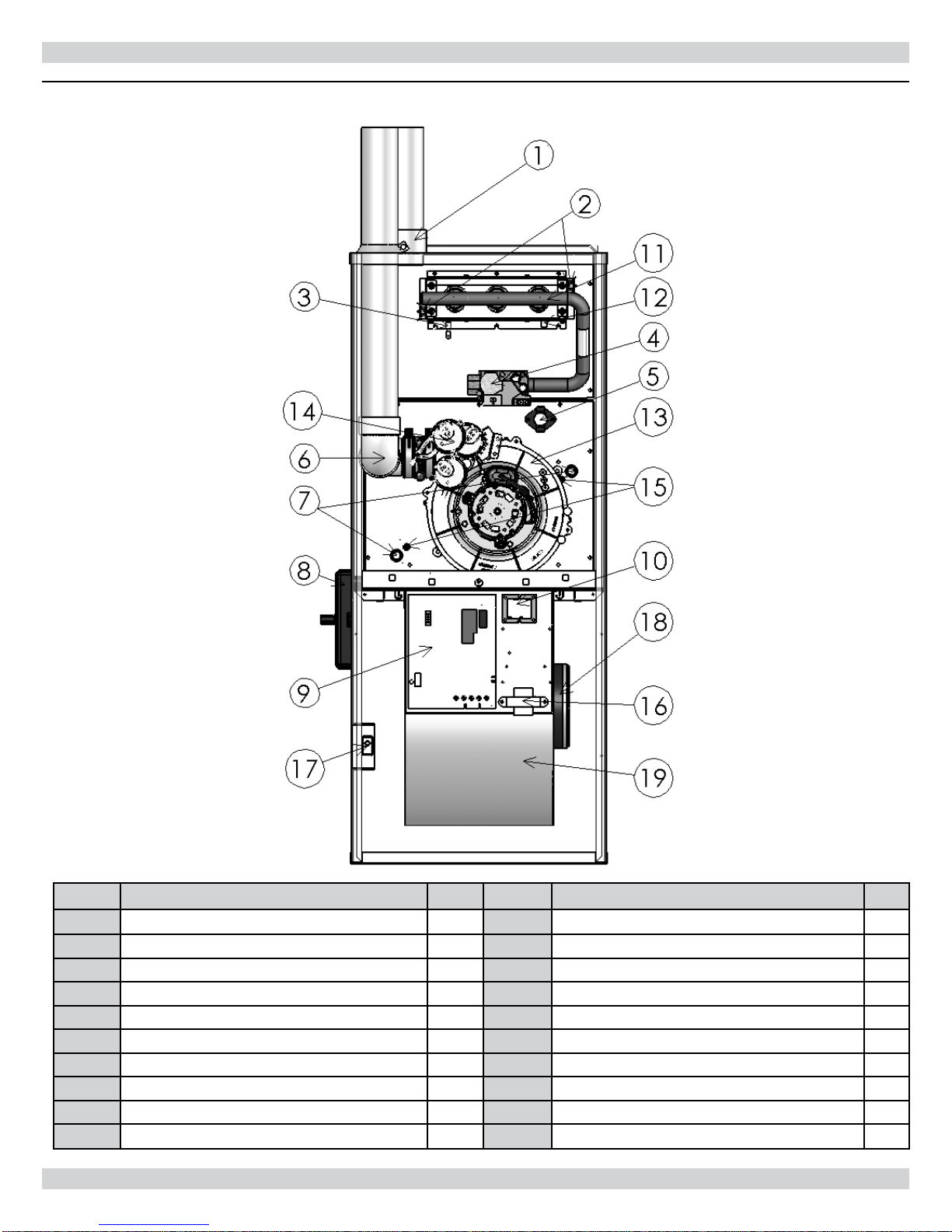
Figure 3 – Furnace Components
3 INSTALLATION REQUIREMENTS
Item Description Qty Item Description Qty
Combustion Air Intake Fitting
1
2 Flame Roll-out Switch 2 12 Igniter 1
3 Flame Sensor 1 13 Two Speed Induced Dra Blower 1
4 Two Stage Gas Valve 1 14 Pressure Switch Assembly 1
5 Air High Temperature Limit 1 15 Front Manifold Cover Pressure Tap 2
6 Vent and Drain Assembly 1 16 PFC “Choke Coil” 1
7 Drain for Recovery Coil 2 17 Door Switch and Junction Box 1
8 Condensate Trap 1 18 ECM Blower Motor 1
9 Two Stage Integrated Control Board 1 19 Blower 1
Transformer for 24 VAC
10
1 11
1
8
Burner Assembly
1
Page 9
Furnace Sizing
4 FURNACE SIZING
e maximum hourly heat loss for each heated space shall be calculated in accordance with the procedures described in the manuals of
the Heating, Refrigeration and Air Conditioning Institute of Canada
(HRAI), or by any other method which is suitable for local conditions, provided the results obtained are in substantial agreement
with, and not less than those obtained using the procedure described
in their manuals.
In the United States, “Manual J - Load Calculation,” published by
the Air Conditioning Contractors of America, describes a suitable
procedure for calculating the maximum hourly heat loss.
If the installation is a retro t application, do not rely on the capacity of the existing heating equipment as a method to size the new
furnace. Many of the heat transfer multiples listed in earlier versions
of load calculation manuals were much higher than those listed in
more recent editions. It is possible that energy saving measures have
been completed since the installation of the existing furnace. is
might include additional insulation in the attic or walls, the application of sprayed foam insulation, the addition of storm windows and
doors, weather-stripping, caulking, etc.
Many of the older furnaces were equipped with large belt drive blower systems, operating at low RPM’s. If replacing an existing furnace,
be sure that the existing ductwork can handle the amount of air ow
necessary for a reasonable temperature rise. Most older gas furnaces
operated with a system temperature rise of 70° - 100°F. is furnace
is designed to be operated with a system temperature rise (∆T) of
High Fire 35° - 65°F, Low Fire 25° - 55°F. If the furnace selected has
an identical output capacity as the original furnace, a substantial
increase in system air ow will be required. See
Tables 3A and B
and the air ow characteristics in Section 23 of this manual,
“Air ow.”
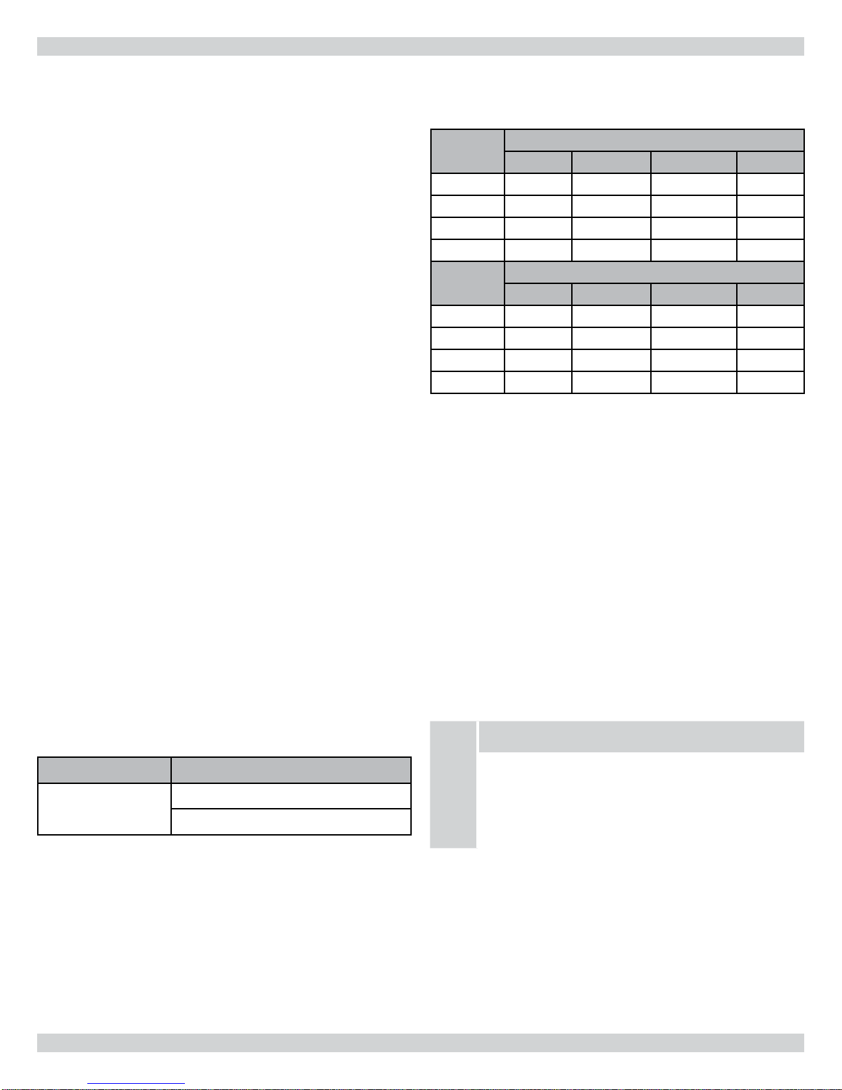
TABLE 3A RANGE OF TEMPERATURE RISE
Furnace Model Temperature Rise
High Fire (HF) 35 - 65°F
60, 80, 100, 120
Low Fire (LF) 25 - 55°F
TABLE 3B - AIR FLOW FOR TEMPERATURE RISE
▲
Furnace
Model
High Fire (HF) CFM Required for a
35 45 55 65
T of F
60 1501 1167 955 808
80 2001 1557 1274 1078
100 2502 1946 1592 1347
120 3002 2335 1910 1616
▲
Furnace
Model
Low Fire (LF) CFM Required for a
25 35 45 55
T of F
60 901 700 573 485
80 1201 934 764 647
100 1501 1167 955 808
120 1801 1401 1146 970
Existing ductwork should be assessed for its air handling capabilities. For residential applications, the recommended air velocity of
a supply air trunk duct is 700 feet per minute (fpm), and should
not exceed 900 fpm. e recommended air velocity of a supply air
branch run is 600 fpm, and should not exceed 900 fpm. ese values
are slightly lower for exible ducting. e recommended air velocity of a return air trunk duct is 600 fpm, and should not exceed 700
fpm. e recommended and maximum air velocity of a return air
branch 600 fpm.
e “Equal Friction Chart,” as published by ASHRAE and HRAI, is
the basis for the various air duct calculators available through heating supply companies. Following the air velocity guide lines, according to the “Equal Friction Chart,” or a slide rule air duct calculator, a
typical 6” round duct has a capacity of approximately 100 cfm.
NOTICE
e return air system is equally as important as the supply
air system. An under-sized return air system will prevent
su cient quantities of air from reaching the supply air
system and will consequently reduce the service life of the
furnace and its components.
9
Page 10
5 LOCATION OF UNIT
1.
General Guidelines
A. Select a location where the exhaust and combustion air pip-
ing can be routed between the furnace and their terminations with a minimum of lengths and ttings. Be sure to
check that the proposed termination location will meet
code requirements with respect to location and minimum
clearances. (See venting section for minimum and maximum limits.)
B. Select a location as near as possible to the existing or pro-
posed duct system.
C. e furnace location must have provisions for condensate
drainage. If a suitable drain is unavailable near the furnace,
a condensate pump must be used. e condensate pump
drain tubing must not terminate outdoors; similar to some
air conditioning condensate installations. Be sure to select
a condensate pump that has been approved for furnace
condensate applications.
D. e furnace location must permit access for servicing
and be within the clearance to combustibles guidelines as
marked on the appliance rating plate.
E. e furnace must be installed level to allow for the proper
drainage of condensate. e furnace may shut down during
winter operation if the condensate does not drain freely
away from the furnace.
F. e furnace should be installed on a rm base when in-
stalled in the up ow position. is would typically be the
concrete oor if installing the furnace in a basement.
G. If the furnace is being installed so that the return air will
enter through the bottom, the perimeter of the furnace
must be properly supported.
H. When installed in the horizontal position, the furnace may
be supported from the bottom, or suspended. (Figure 3)
I. If the furnace is to be installed in a commercial (repair) ga-
rage, the burners and ignition source must be a minimum
of 4½ feet (1375 mm) above the oor. e furnace must be
protected from physical damage by metal barriers or other
acceptable means.
2.
Other considerations
A. If the furnace is to be located in an area where the combus-
tion air is laden with chemical compounds such as bromine, chlorine or uorine, as may be found in swimming
pool chemicals, laundry detergents, etc., use outdoor air
for combustion. ese compounds when exposed to ame,
form acids which attack the heat exchanger and other components. A partial list of contaminants would include:
• Aerosols, particularly CFC based aerosols
• Air fresheners
• “Airplane” glue and similar cements
• Ammonia, as is commonly found in permanent wave solutions used in women’s hair dressing salons
• Anti-static fabric so eners used in clothes dryers
• Carbon tetrachloride
• Chlorinated cleaners and waxes
• Chlorine and bromine based swimming pool chemicals
and treatments
• De-icing salts or chemicals, rock salt, etc.
• Dry cleaning solutions such as perchloroethylene
• Halogen based refrigerants including R-12 and R-22
• Hydrochloric acid, muriatic acid, or other acid based masonry washing compounds
• Polyurethane and similar derivatives fumes
• Printer’s inks, paint removers, furniture strippers, varnishes, varsol, toluene, etc.
• Water so ener salts and chemicals
NOTICE
IMPORTANT: is furnace is not to be used for temporary heating of buildings or structures under construction.
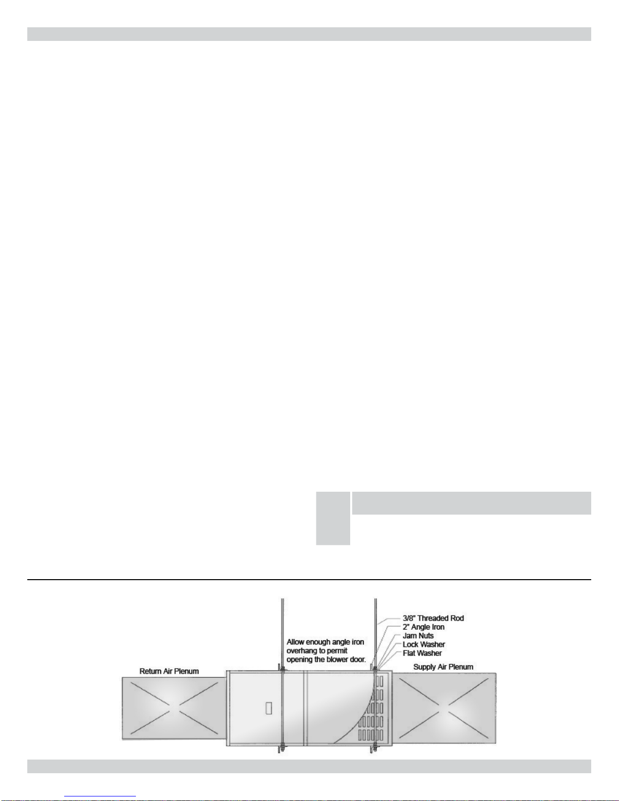
Figure 4 - Suggested Method For Suspending Horizontal Furnace
10
Page 11

5 LOCATION OF UNIT
B. If this furnace is to be installed in an area over a nished
ceiling or living area, install a eld fabricated auxiliary
drain pan under the furnace to protect that area from accidental condensate spills. e auxiliary pan should be large
enough to collect accidentally spilled condensate from the
air conditioning evaporator coil assembly if applicable.
e opening in the oor must provide adequate clearances to the
combustible material. A ½” clearance will be required between
the plenum and the combustible material. For sections of plenum
with direct line of sight with heat exchanger, a 1” clearance will be
required. If installed on a non combustible material, zero clearance
is required. Optional subbase kit 550001346 will assist in achieving
required clearances.
NOTICE
ese furnaces are approved for installation in attics,
alcoves, utility rooms, closets and crawl spaces. If this
furnace is to be installed in a utility room, be sure that it
is located in such a way as to allow access for servicing or
the removal of other appliances installed in the room (hot
water heater, for example).
C. If the furnace is installed in an area where freezing may oc-
cur, a garage, an attic, a crawl space or any unconditioned
space, steps must be taken to protect the condensate trap
and drain line from freezing. One possible measure could
be to use a self-regulating 5 or 6 watt per foot heat tape
covered with a jacket of insulation. Heat tapes are available
in plumbing supply houses.
NOTICE
IMPORTANT: e rear of the furnace must be elevated
1/4” higher than the front from a level position to facilitate
proper condensate drainage.
NOTICE
IMPORTANT: If the furnace and air conditioner is above a
nished space, install a drain pan underneath the unit.
NOTICE
NOTE: It is not permissible to use a rear return on this
appliance. Use only side and end returns.
3.
INSTALLATION IN UPFLOW, DOWNFLOW OR HORIZONTAL POSITIONS
• UPFLOW INSTALLATION: Vent positioning, pressure
switch location and drain locations shall be performed in accordance with instructions in the appropriate sections of this
manual.
• HORIZONTAL INSTALLATION: Vent positioning, pressure switch location and drain locations shall be performed
in accordance with instructions in the appropriate sections of
this manual.
• NON-SUSPENDED INSTALLATION: Maintain clearances to combustibles as outlined in
Figure 2, Table 2
e furnace must be supported in such a way as to not allow
twisting or sagging of the cabinet.
• SUSPENDED INSTALLATION: Maintain clearances to
combustibles as outlined in
Figure 2, Table 2
. e furnace
may be suspended by eld fabricating a cradle of angle iron
and threaded rod. Secure the furnace with 2” minimum slotted angle or equivalent as shown in
Figure 4.
e furnace
must be supported in such a way as to not allow twisting or
sagging of the cabinet. Position the supports so as to not interfere with accessing the burner and blower compartments.
4.
AIR CONDITIONING is furnace may be used as part of an
air conditioning system. e furnace wiring and control system
is “air conditioning ready.” ere are the following factors to
consider:
• e air conditioning evaporator coil must be downstream
of the heat exchanger. e cooled air passing over the
warmer heat exchanger tubes can cause condensation inside the tubes, resulting in corrosion and premature failure.
• A parallel duct system can be installed to direct the air from
the furnace through the evaporator coil only. Use dampers
.
or other means to bypass the heat exchanger. If (summer/
winter) dampers are used, they should be interlocked to
prevent system operation unless the dampers are in the full
open or full closed position.
5 - COMBUSTIBLE CLEARANCES
• DOWNFLOW INSTALLATION: Vent positioning, pres-
sure switch location and drain locations shall be performed
in accordance with instructions in the appropriate sections of
this manual.
11
Page 12
6 COMBUSTIBLE CLEARANCES
Combustible Clearances
Figure 2, Table 2
and dimensional information. Also see the appliance rating plate
a xed to the furnace for speci c model number, serial number and
clearance to combustibles information.
IMPORTANT: is furnace requires a minimum of 24”
of front clearance for service purposes. For this purpose,
service clearance takes precedence over clearance to combustibles.
is furnace is design certi ed for installation on combustible oors. is shall be interpreted as a wood oor only.
!
e furnace must not be installed directly on carpeting,
tile, or other combustible material except wood.
Installation on combustible material can result in re,
causing property damage, personal injury or death.
provides the certi ed clearances to combustibles
NOTICE
WARNING
e area around the furnace must be kept clear and free
of all combustible materials including gasoline and other
ammable vapors and liquids.
!
e homeowner should be cautioned that the furnace area
must not be used as a broom closet or for any other storage
INSPECTION / ACCESS PANEL
purpose.
WARNING
Inspection / Access Panel
If an air conditioning coil is not to be used in the supply air plenum,
it is recommended that the outlet duct be provided with a removable
access panel which is accessible when installed so the heat exchanger
may be inspected for possible openings using light assistance or a
probe that can be inserted for sampling the air stream. e access
cover must be fabricated in such a manner as to prevent leaks.
6 - DUCTWORK
7 DUCT WORK
Proper air ow is required for the correct operation of this furnace.
Insu cient air ow may cause erratic operation, could cause the
furnace to cycle on the high temperature limit, and may damage the
heat exchanger. Excessive air ow may result in an excessively noisy
duct system and may result in undesirable consequences such as
creating uncomfortable dra s and causing drapes or curtains to blow
around.
If air conditioning is to be used with the furnace, the duct system
must be capable of delivering the correct amount of air ow for each
system.
e ductwork should be sized and constructed in accordance with
accepted industry standards. Duct sizing and construction information may be obtained from:
• A.C.C.A. (Air Conditioning Contractors of America)
• A.S.H.R.A.E. (American Society of Heating, Refrigeration
and Air Conditioning Engineers
• H.R.A.I. (Heating, Refrigerating and Air Conditioning
Institute (Canada)
• S.M.A.C.N.A. (Sheet Metal and Air Conditioning Contractors’ National Association (United States)
e total static pressure drop of the air distribution system (including lters) should not exceed
1.0” w.c.
WARNING
Do not allow gas piping to be routed through joist spaces
that are used for return air purposes. Do not use joist spac-
!
es for return air purposes if the joist space already contains
plumbing stacks, chimney components, etc. Unless the
portion used for return air purposes can be completely
isolated from portions with other usages
WARNING
Failure to prevent products of combustion from being circulated into the living space can create potentially hazardous conditions, including carbon monoxide poisoning that
could result in personal injury or death.
!
Do not, under any circumstances, connect return or supply
air ductwork to or from any other heat producing device
such as a replace insert, stove, etc. Doing so may result
in re, carbon monoxide poisoning, explosion, personal
injury, loss of life, or property damage
All of the above professional organizations have duct sizing manuals
available.
12
Page 13
7 DUCTWORK
WARNING
Never allow the products of combustion from the ue to
enter the return air or supply air ductwork.
1.
Position the furnace to minimize ductwork length and ttings.
2.
Cut open a return air inlet. e choices are furnace bottom,
either side, or any combination thereof (i.e., two sides or a side
and the bottom).
All return air ductwork must be adequately sealed and
secured to the furnace with sheet metal screws. Tape the
sheet metal seams in the vicinity of the furnace with duct
!
tape or similar material.
When the furnace is mounted on a platform with return
air through the bottom, it must be sealed air tight between
the furnace and the return air plenum. e oor or platform must provide sound physical support of the furnace
without sagging, cracks or gaps around the base, providing
a seal between the support and the base.
Models capable of 5 tons of air ow for air conditioning must have
dual return air inlets for optimal air ow and air ltration. If not
speci cally stated by the lter manufacturer, for e ective air ltration
assume a maximum velocity of 300 FPM for disposable type lters or
600 FPM for permanent type air lters.
GUIDE: Filter free area (in
2
) = 144 x (CFM / desired velocity (FPM))
WARNING
DO NOT USE THE REAR PANEL AS A RETURN AIR
!
INLET. ere is insu cient room to permit adequate
air ow.
In all cases, cut the inlet air opening the full width of the knockouts.
3.
Connect the return air duct or lter tting to the furnace. e
connection should be sealed air tight to prevent entraining
combustion gases from an adjacent fuel burning appliance,
or entraining combustion air for this furnace or adjacent fuel
burning appliances.
4.
Ensure that there is adequate space and accessibility for air lter
removal.
NOTICE
NOTE: If two return air inlets are used, both must be
equipped with lters.
5.
If an air conditioning evaporator coil is required, position it on
the supply air side of the furnace. Ensure that no air can bypass
the evaporator coil.
6.
Connect the supply air plenum to the supply air outlet.
NOTICE
IMPORTANT: Some high e ciency lters have a greater
than normal resistance to air ow. is can adversely a ect
furnace operation.
Ductwork Steps
8 VENTILATION AND COMBUSTION AIR
WARNING
READ, UNDERSTAND AND FOLLOW ALL INSTRUCTIONS IN THIS SECTION. FAILURE TO PROPERLY
VENT OR SUPPLY COMBUSTION AIR TO THIS FUR-
!
NACE CAN CAUSE CARBON MONOXIDE POISONING, OR AN EXPLOSION OR FIRE, RESULTING IN
PROPERTY DAMAGE, PERSONAL INJURY OR LOSS
OF LIFE.
“Vent and Chimney” refer to open passageways that convey vent gas-
ses from the furnace, or its vent connector to the outside. Vents can
be horizontal or vertical. When they serve only one gas appliance,
they are called “dedicated” vents or chimneys. When they serve multiple gas appliances, they are called “common” vents or chimneys.
“Vent C onn e cto r ” refers to a pipe or duct that connects the furnace
Flexible duct connectors are an e ective device to prevent the telegraphing of mechanical noise from the furnace to other parts of the
home via the ductwork. If using exible connectors, ensure that the
adjoining duct is independently supported.
De nitions
to a vent or chimney. Vent connectors usually run from the furnaces
vent collar to the vent or chimney. Vent connectors may have vertical
and horizontal runs.
“Venting System” refers to a continuous open passageway from
the vent collar to the outside. Venting systems usually have a vent
connector(s) and a vent or chimney. Venting systems commonly
serve a single furnace, or a single furnace and a hot water heater.
Other multiple appliance venting systems are less common.
“Fan Assisted Combustion System” refers to an appliance equipped
with an integral mechanical means to either draw or force products
of combustion through the combustion chamber and/or heat exchanger. is series furnace uses a dra inducer to draw combustion
products through the heat exchanger and is considered to have a fanassisted combustion system. Category IV furnaces with fan-assisted
13
Page 14

8 VENTILATION AND COMBUSTION AIR
combustion systems must not be vented into single wall metal vents.
General Considerations
If this furnace is to replace a Category I type furnace connected to a
chimney serving other appliances, steps must be taken to ensure that
the remaining appliances will vent properly a er the removal of the
existing furnace. ere is a probability that the existing chimney will
be too large.
Remove the vent connector of the furnace being replaced, seal o the
inlet to the vent from that furnace, then test the remaining appliances connected to the common vent individually following these steps:
1.
Permanently seal any unused openings into the common vent
system.
2.
Visually inspect the venting system for proper size and horizontal pitch and determine that there is no blockage, restriction,
leakage, corrosion, collapsed materials such as fallen bricks, or
any other de ciency that could lead to an unsafe condition.
3.
Insofar as practical, duplicate winter operating conditions such
as closing all windows and doors in the building. If the remaining appliances are in a mechanical room, close the door to the
room. Close the replace dampers if any, turn on any appli-
ances that exhaust air to the outdoors on maximum speed. is
would include clothes dryers, range hoods, bathroom fans, etc.
Attic fans or other fans used only in summer should be exempted from the test.
4.
Follow the lighting instructions of the appliance being tested
and turn it on to continuous operation.
5.
Test for spillage at the dra hood relief opening a er 5 minutes
of main burner operation. Detect for spillage using a match
ame, taper (candle).
6.
A er it has been proven that each appliance to remain connected to the common venting system properly vents when tested
as listed above, return the windows, doors, replace dampers,
appliances, etc. to the condition they were in prior to the test.
7.
If improper venting is observed during any of the tests, the
common venting system must be re-sized. In Canada, refer to
the latest addition if CAN/GGA-B149, Natural Gas or Propane
Installation Code. In the United States, refer to the latest ANSI
Z223.1 National Fuel Gas Code (NEPA 54), or AGA-GAMA
Venting Tables for Category I furnaces.
e furnace products of combustion include both ue gases and
condensate. All venting and drain materials are plastic.
9 VENTING AND COMBUSTION AIR PIPING
Acceptable Materials In The United States
For United States installations, the combustion air and vent piping
and ttings may be comprised of:
• Schedule 40 PVC, ASTM D1785 or CSA B137.3
• PVC-DWV, ASTM D2665 or CSA B181.2
• Schedule 40 CPVC, ASTM F441 or CSA B137.6
• PVC PRIMER AND SOLVENT CEMENT: ASTM D2564
Follow piping manufacturers instructions on proper installation of
piping and ttings including cutting, de-burring, priming, cementing, curing and supporting.
Acceptable Materials In Canada
E ective August 1, 2007, all vent piping materials and ttings for ue
gas venting must be ULC S636 listed and identi ed as such on the
material. e rst 3 . (900mm) of venting must be readily available
for visual inspection. Speci ed primers and glues of the certi ed
vent system must be from a single system manufacture, and not
intermixed with other system manufacture’s vent system parts. e
components of the certi ed vent system must not be interchanged
with other vent systems, or unlisted pipe, and or ttings. Follow the
venting manufacturers instructions on installation, cutting, de-burring, cementing, curing and supporting of the venting system.
is furnace can be vented with ULC S636 certi ed PVC material
with a rating of 65º C or more.
e supplied PVC street elbows are certi ed for use within the vestibule. Use the approved transition cement certi ed by the ULC S636
venting supplier.
e optional Concentric Vent Termination Kits are certi ed for use.
Use the approved transition cement certi ed by the ULC S636 venting supplier.
e combustion air piping does not have ue gases traveling through
it and may be installed with common ABS, PVC or CPVC piping
or ttings. is piping, ttings, primer and cement will need to be
installed as per the manufacturers instructions including cementing,
cutting, curing and supporting the piping.
14
Page 15
10 NONDIRECT VENT FURNACE INSTALLATIONS USING INDOOR COMBUSTION AIR
e furnace, although designed as a direct vent type appliance, may
be installed with the intake vent inside the structure.
WARNING
THIS FURNACE AND ANY OTHER FUEL BURNING
APPLIANCE MUST BE PROVIDED WITH ENOUGH
FRESH AIR FOR PROPER COMBUSTION AND VEN-
!
TILATION OF THE FLUE GASES. MOST HOMES WILL
REQUIRE THAT OUTSIDE AIR BE BROUGHT TO THE
FURNACE AREA. FAILURE TO DO SO CAN CAUSE
PERSONAL INJURY, OR DEATH FROM CARBON
MONOXIDE POISONING.
Adequate provisions for combustion and ventilation air must be
in accordance with CAN/CGA-B149 in Canada, and ANSI Z223.1
- 1992, section 5.3, “Air for Combustion and Ventilation,” in the
United States. Check with local authorities for any additional building codes bylaws or regulations.
CAUTION
Air for combustion and ventilation purposes must not
!
originate from a corrosive atmosphere. Any furnace failure
caused by corrosive elements is excluded from warranty
coverage.
e following types of installation sites (but not limited to the following) will REQUIRE OUTDOOR AIR for combustion because of
chemical exposures:
Exposure to the following substances in the combustion air supply
(but not limited to the following) will also require OUTDOOR AIR
for combustion:
• Aerosols, particularly CFC based or propelled aerosols
• Air fresheners
• “Airplane Glue” and similar adhesives and cements
• Ammonia, as commonly found in permanent wave solutions used in hair dressing salons
• Anti-static fabric so eners used in clothes dryers
• Carbon tetrachloride
• Chlorinated cleaners and waxes
• Chlorine and bromine based swimming pool chemicals
• De-icing salts or chemicals (rock salt, etc.)
• Dry cleaning uids such as perchloroethylene
• Fumes from curing polyurethane and similar substances
• Halogen based refrigerants including R-12 and R-22
• Hydrochloric acid, muriatic acid and other acid based
masonry washing and curing materials
• Printer’s inks, paint removers, varnishes, varsol, toluene,
etc.
• Water so ener salt and chemicals
• Commercial buildings
• Buildings with indoor swimming pools
• Furnaces installed in laundry rooms
• Furnaces in hobby or cra rooms
• Furnaces installed near chemical storage areas
11 DETERMINING COMBUSTION AIR
CASE 1 - Furnace Located In An Uncon ned Space
Uncon ned space does not necessarily mean that ventilation will
not have to be introduced from the outdoors, particularly in airtight
homes. e minimum requirement for uncon ned space is a volume
of 50 cubic feet for each 1000 BTU/Hr for all fuel burning appliances
located within the uncon ned area.
If the amount of combustion and ventilation air is insu cient to
properly operate the furnace and other fuel burning appliances
within the uncon ned area, it will be necessary to supply it from the
outdoors based on the criteria used when calculating the air supply
for a con ned space.
Combustion air must be free of acid forming chemicals such as
sulphur, uorine and chlorine. ese elements are found in aerosol
sprays, detergents, bleaches, cleaning solvents, air fresheners, paint
and varnish removers, refrigerants, and many other commercial and
household products. When burned in a gas ame, vapors from these
products form acid compounds. Acid compounds increase the dew
point temperature of the ue products and are highly corrosive a er
they condense.
NOTICE
NOTE: If planning to use the inside air in an uncon ned
space, remember to test for proper furnace operation (as
well as other fuel burning appliances located within the
uncon ned space) with respect to adequate combustion
and ventilation air with replace dampers open, clothes
dryer running, bathroom exhaust fans on, kitchen range
hood on, etc.
CASE 2 - Furnace Located In A Con ned Space
A con ned space, (any space smaller than the minimums discussed
15
Page 16
11 DETERMINING COMBUSTION AIR
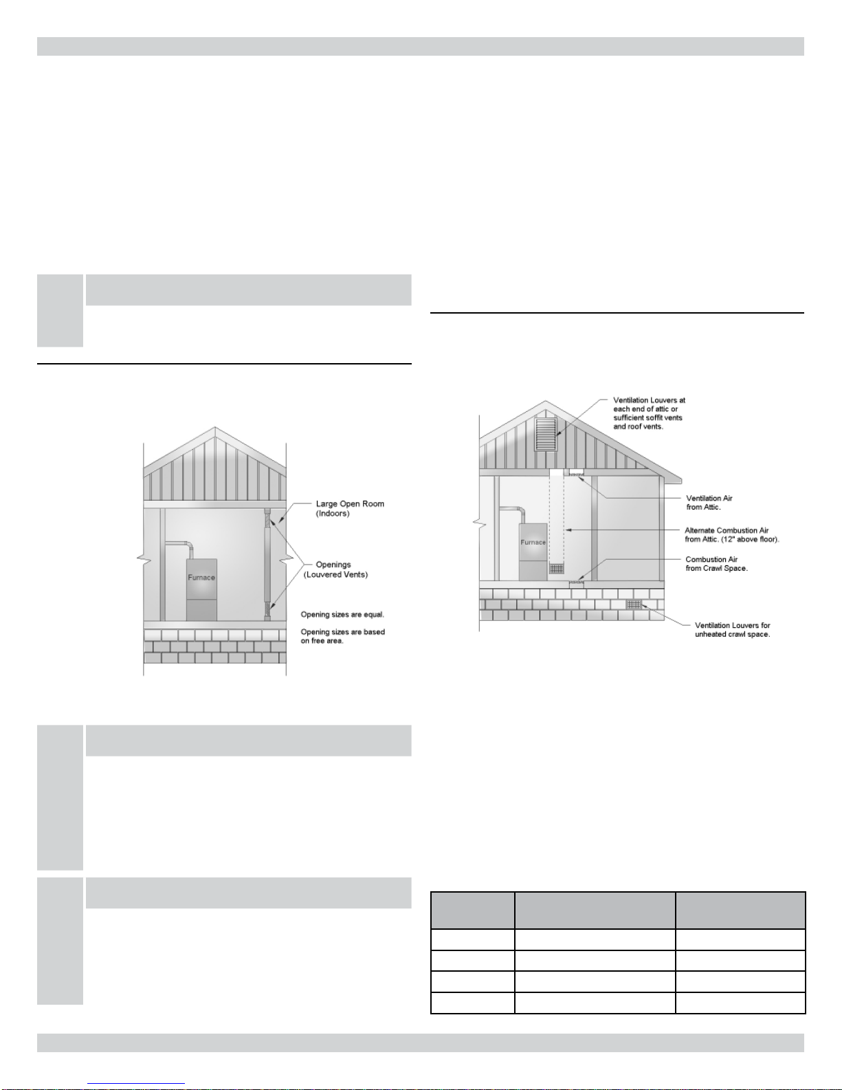
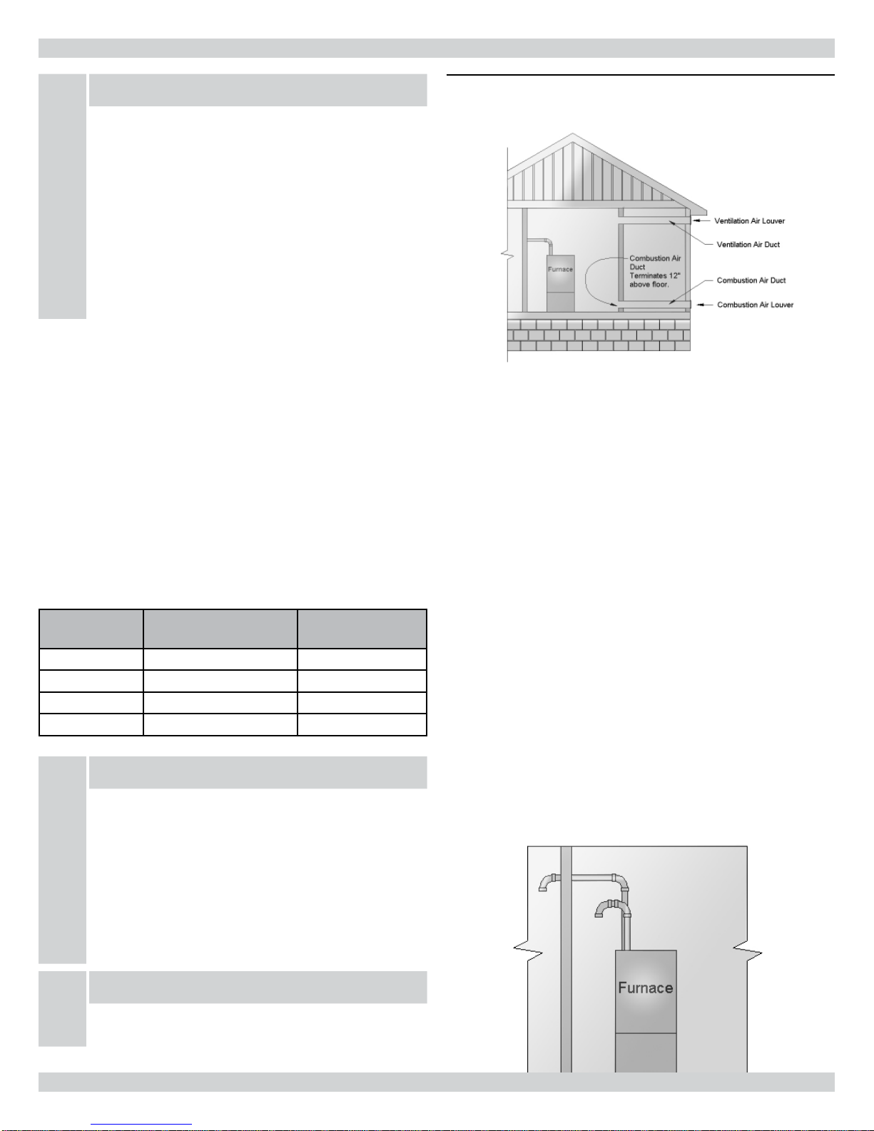
in Case 1), must have two air openings; one within 12” of the ceiling
and the other within 12” of the oor. e air openings must be sized
based on whether the combustion and ventilation air is being taken
from indoors or outdoors, the method outdoor air (if used) is introduced, and taking into account any other fuel burning appliances in
the con ned space.
If su cient indoor combustion and ventilation air is available for the
furnace and all other fuel burning appliances, size each opening on
the basis of one square inch of free area per 1000 BTU/Hr. (
5
)
Figure
NOTICE
NOTE: Be sure to consider all clothes dryers, bathroom
fans, range hoods, etc., when making this calculation.
Figure 5 - Combustion/Dilution Air From Heated Inside
Sources (Case 2)
CASE 3 - Furnace Located In A Con ned Space, Outdoor
Air From Attic Or Crawl Space
In this circumstance, the free area of each of the two combustion and
ventilation air openings is based on a minimum of 1 square inch per
4000 BTU/Hr. In this con guration, one opening can originate from
the oor drawing combustion and ventilation air from the ventilated
crawl space.
e other opening may communicate freely with a ventilated the
attic. If using the attic air, ensure that the opening is ducted from
the ceiling high enough to be above the insulation. e attic must be
adequately vented with so t vents or gable vents. (
Figure 6
)
Figure 6 - Outside Air For Combustion, Attic Or Crawl
Space (Case 3)
e minimum requirement for these openings is 100 square inches,
even for the furnace models under 100,000 BTU/Hr.
NOTICE
NOTE: If using grilles to cover the two openings, factor
in the free area of the grille. Typically, a sidewall grille will
have a free area approximately 50% of its nominal size.
Consequently, if the required opening is 10 x 10, it will
have to be doubled if using a sidewall grille with 50% free
area.
NOTICE
IMPORTANT: If an exhaust fan, replace, clothes dryer or
any similar device is present in the indoor area from which
the combustion and ventilation air will be drawn, negative
pressure could be a problem if natural in ltration from the
outdoors does not match the rate at which air is exhausted.
As an alternative to creating an opening in the oor to draw air from
a crawl space, a duct may be dropped from the attic terminating 12”
above the oor.
e following table (
Table 4
) shows minimum free areas and round
pipe sizes when drawing combustion air vertically from the attic or
crawl space for the furnace only. If other fuel burning appliances are
present, their combustion air and ventilation air requirements must
be added to those of the furnace.
TABLE 4 - VERTICAL AIR SUPPLY (CASE 3)
Model
60 15 in.² 5 in.
80 20 in.² 6 in.
100 25 in.² 6 in.
120 30 in.² 7 in.
Free Area
Ea. Opening
Round Pipe Size
16
Page 17
11 DETERMINING COMBUSTION AIR
NOTICE
IMPORTANT: If the attic has an exhaust fan (power
vent), it may create a negative pressure su ciently large
enough to prevent the attic from being an e ective source
of combustion and ventilation air. Powered attic fans do
not customarily run during the heating season; however,
some are controlled by a humidistat as well as a thermostat, which may allow some operation during the heating
season. e choices are (a) use the direct vent option; (b)
obtain outdoor air from elsewhere; or (c) interlock the
attic exhaust fan with the furnace such that the two cannot
operate simultaneously.
CASE 4 - Furnace Located In A Con ned Space, Outdoor Air
Ducted Horizontally
Similar to Case 3, outdoor air for combustion and ventilation may
be drawn through horizontal ducting. e free area for each opening
is calculated on the basis of a minimum of 1 square inch per 2000
BTU/Hr input.
e following table shows minimum free areas and round pipe sizes
when drawing combustion air horizontally from the outdoors for
the furnace only. If other fuel burning appliances are present, their
combustion air and ventilation air requirements must be added to
those of the furnace.
TABLE 5 - HORIZONTAL AIR SUPPLY (CASE 4)
Model
60 30 in.² 7 in.
80 40 in.² 8 in.
100 50 in.² 8 in.
120 60 in.² 9 in.
IMPORTANT: If grilles are used on the outside wall, they
must be sized properly. Most sidewall grilles have only 50%
free area. In the case of a unit with 100,000 Btuh input,
which requires a pair of 8” round pipes to obtain su cient
combustion and ventilation air, the duct could be an equivalent rectangular duct; 8” x 7” for example. Based on 50%
free area for the inlet grilles, the actual grille size would
have to be 14” x 8” or its equivalent. A transition may be
used to reduce to the smaller duct size if necessary.
Free Area
Ea. Opening
NOTICE
Round Pipe Size
Figure 7 - Outdoor Air For Combustion, Horizontal (Case 4)
CASE 5 - Furnace Located In A Con ned space, Outdoor Air
Ducted with Single Opening (US Only)
One permanent opening, commencing within 12 in. (300 mm) of
the top of the enclosure, shall be provided. e appliance shall have
clearances of at least 1 in. (25 mm) from the sides and back and 6 in.
(150 mm) from the front of the appliance. e opening shall directly
communicate with the outdoors or shall communicate through a
vertical or horizontal duct to the outdoors or spaces that freely communicate with the outdoors and shall have a minimum free area of
the following:
1.
1 in2/3000 BTU/hr (700 mm2 per kW) of the total input rating
of all appliances located in the enclosure, and
2.
Not less than the sum of the areas of all vent connectors in that
space”
Connection To Furnace Non-Direct Vent
When using indoor air or the non-direct vent con guration, the
combustion air inlet to the furnace must be protected from blockage. Use a double elbow arrangement if supplying combustion air
through the top, or a downward pointing single elbow if supplying
combustion air through the side. (
Figure 8
)
Figure 8- Non-Direct Combustion Air Inlet
NOTICE
IMPORTANT: e outdoor grilles must be installed in a
location where they will not be obstructed in any manner.
17
Page 18
12 VENTING GUIDELINES
CAUTION
Failure to follow all venting guidelines may result in erratic
!
furnace operation, freeze-up of the exhaust air piping, or
sooting of the furnace.
WARNING
READ AND FOLLOW ALL INSTRUCTIONS IN THIS
SECTION. FAILURE TO PROPERLY VENT THIS FUR-
!
NACE CAN CAUSE CARBON MONOXIDE POISONING OR AN EXPLOSION OR FIRE RESULTING IN
PROPERTY DAMAGE, PERSONAL INJURY OR LOSS
OF LIFE.
NOTICE
NOTE: Combustion air intake and exhaust termination
should be inspected periodically to ensure they are clear of
obstructions. i.e. vegetation, debris, snow, etc.
NOTICE
NOTE: Accumulation of snow around the combustion air
intake and exhaust termination may have negative e ects
on appliance operation and/or performance. Snow accumulation should be considered when locating combustion
air intake and exhaust terminations.
• If venting vertically, do not vent up a chimney serving
another appliance or install in a chase with a metal or high
temperature plastic pipe from another gas or fuel burning
appliance unless the required clearances to combustibles
can be maintained between the furnace venting system and
other pipes.
All exhaust piping must be installed in accordance with CAN/CGAB149.in Canada; the latest edition of National Fuel Gas Code, NFPA
54 / ANSI Z223.1 in the United States, as well as in accordance with
local codes.
Size the combustion air and exhaust piping in accordance with
Table 6
all termination ttings in addition to counting the concentric vent as
a straight pipe.
Take the building orientation and the presence of other buildings
or other nearby structures into consideration when planning the
venting system location. Certain external structures could create air
turbulence around the vent termination leading to downdra s and
similar venting problems. In windy and hill locations, roof venting
may improve operations. Maximum venting length is based on 30
mph winds, areas where higher gusts are dominant it is suggested to
shorten the horizontal vent length.
e vent and combustion air intake shall be installed so that both are
located in the same wind pressure zone.
. When calculating allowable vent lengths, be sure to count
• Venting may be vertical or horizontal.
• Minimum vent length - 25 total equivalent feet.
Venting Table6)
• Horizontal piping must slope back towards the furnace at a
minimum rate of ¼” to the foot, so that condensate drains
towards the furnace.
• Horizontal runs must be supported at least every 3 feet.
Horizontal sections must not dip or sag.
• All vent runs through unconditioned space where freezing
might occur should be insulated with 1” thick, medium
density, foil-faced Fiberglass insulation. An equivalent
“arm-a- ex” or “rub-a-tex” may also be used as long as
there is no heat tape applied to the vent pipe. For horizontal runs where water may collect, wrap the vent pipe with
self regulating 3 or 5 watt heat tape. e heat tape must
be CSA, UL, or ULC listed and installed per the manufacturer’s instructions.
• DO NOT COMMON VENT WITH ANY OTHER APPLIANCE.
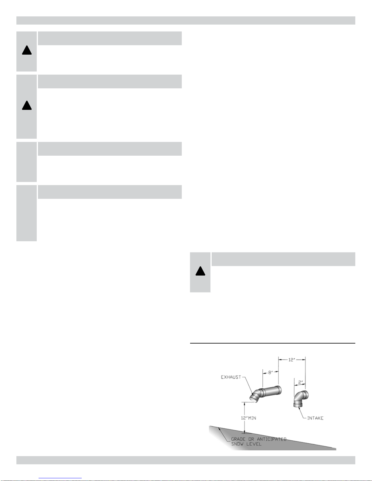
(See
Vent Termination
Horizontal vents should pass through the exterior wall.
shows a standard horizontal vent detail. Terminate the vent approximately 8” or more from the wall.
Figure 9 - Standard (Straight) Horizontal Vent Detail
WARNING
DO NOT CONNECT FURNACE TO A CHIMNEY OR
!
FLUE SERVING OTHER APPLIANCES OR A SOLID
FUEL BURNING APPLIANCE.
Figure 9
18
Page 19
12 VENTING GUIDELINES
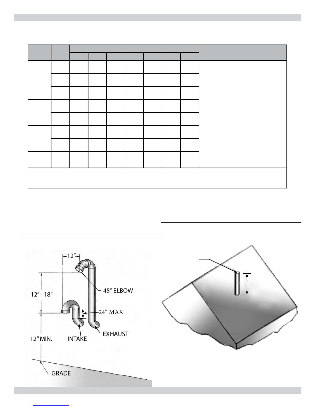
TABLE 6 - DIRECT AND NON-DIRECT VENT LENGTHS
MAXIMUM ALLOWABLE LENGTH OF EXHAUST OR INTAKE
MODEL
60
80
100
120 3” 100 95 90 85 80 75 70
When 1½” or 3” pipe is used, exit the cabinet with 2” pipe. Reduce or increase immediately after exiting the
PIPE
SIZE
1½” 25 20 15 10 5 - -
2” 75 70 65 60 55 50 45
3” 100 95 90 85 80 75 70
2” 50 45 40 35 30 25 20
3” 100 95 90 85 80 75 70
2” 50 45 40 35 30 25 20
3” 100 95 90 85 80 75 70
Use of a concentric termination reduces the allowable length by 5 feet from lengths shown in this table.
0123456
cabinet making provisions to secure the vent bracket between cabinet and fi tting.
NUMBER OF 90° ELBOWS
NOTES
1. Count concentric vent fi tting as
straight pipe.
2. Use medium or long sweep
elbows where possible.
3. One 90° elbow is equivalent to
two 45° elbows.
4. For direct vent, the listed lengths
are allowed for each vent (intake
and exhaust).
5. For non-direct vent, the listed
lengths are allowed for exhaust.
The intake should have a 1½”
or 2” snorkel intake fi tting.
(
Figure 9
6. Include the 2 vestibule elbows
when calculating total vent length
for all models.
)
Figure 10 - Periscoped Vent Detail
Figure 11 - Vertical Venting
Roof Termination
Exhaust
18” MIN.
19
Page 20

12 VENTING GUIDELINES
If it is not possible to obtain proper clearance to grade by a straight
out con guration, the termination may be raised by the use of a pair
of 90° elbows. (
Besides the initial increaser/reducer, the venting system must stay
consistent in regards to pipe diameter through out the entire vent
length. e vent may also terminate in a vertical venting con guration through the roof. No termination tting is required.
e exhaust pipe extending through the roof must extend 18” above
the highest point where it extends through the roof, surface and
above any obstruction within an 18” horizontal distance. (
11
)
Exterior vent pipe greater than 24” should be insulated with ½”
insulation to prevent moisture from freezing within the pipe and
accumulating.
Size the exhaust pipe as speci ed in
rect Vent Lengths. is table lists the maximum allowable length of
pipe with respect to the number of 90° elbows used. For the purposes of this calculation, one 90° elbow is equivalent to two 45° elbows.
Avoid locating the terminal in locations where dripping condensate
may cause problems such as sidewalks, patios, above planters, near
windows where exhaust gases may cause fogging, etc. Avoid locating the termination too close to shrubs and other vegetation. e
condensate may stunt or kill them.
!
Caulk all cracks, seams or joints within a 6 foot radius of the termination.
Do not terminate under a deck unless there is adequate clearance to
prevent damage from the ue gases. A termination may be located
at the end of a patio deck. Piping running beneath the deck must be
suitably insulated and suspended in a manner to prevent condensate
from collecting and freezing.
Figure 9
NOTE: Length of pipe and elbows count toward maximum
allowable vent length as shown in Table 6.
Moisture in the ue gases condenses as it leaves the terminal. is moisture can freeze on exterior walls, on so ts,
and other nearby objects. Some discoloration is to be
expected; however, improper location or installation can
cause structural or exterior nish damage to the building.
, Exhaust Detail Only)
NOTICE
Table 6
CAUTION
- Direct and Non-Di-
Figure
Do not locate the terminal on the side of the building facing the
prevailing winter winds.
In Canada
In addition to the general guidelines, in Canada, the non-direct vent
exhaust shall not terminate:
• Directly above a paved sidewalk or paved driveway which
is located between two single-family dwellings and serves
both dwellings;
• Less than 7 feet above a paved sidewalk or paved driveway
located on public property;
• Within 6 feet of a mechanical air supply inlet to any building;
• Above a meter/regulator assembly within
3 feet horizontally of the centerline of the regulator;
• Within 6 feet of any service regulator vent outlet;
• Less than 12” above grade level or anticipated snow level;
• Within 12” of any door, window, or non-mechanical air
supply inlet to any building;
• Within 12” of the combustion air inlet of any other appliance;
• Underneath a veranda, porch or deck, unless (a) the veranda, porch or deck is fully open on a minimum of two sides
beneath the oor, and (b) the distance between the top of
the vent termination and the underside of the veranda,
porch or deck is greater than 12”.
In The U.S.A.
In addition to the general guidelines, in the United States, the nondirect vent exhaust shall be installed in accordance with the following:
• e clearance from the bottom of the terminal to grade
shall be 12”.
• e vent shall not terminate over public walkways or over
an area where condensate or vapor could create a nuisance
or hazard.
• e vent terminal shall be installed 4 feet below, 4 feet
horizontally from, or 1 foot above any door, window, so t,
under eave vent or gravity air inlet to the building.
• e vent terminal shall have a minimum horizontal clearance of 4 feet from electric meters, gas meters, regulators
and relief equipment.
• Locate the vent terminal 3 feet above any forced air inlet
located within 10 feet. Any fresh air or make-up air inlet,
such as for a dryer or furnace area is considered a forced air
inlet.
20
Page 21

12 VENTING GUIDELINES
e vent terminal should be located no fewer than 6 feet from an
inside corner formed by two exterior walls; a 10 foot distance is
recommended.
Recommended clearance from overhangs is a minimum of 1 foot
vertically for each foot horizontally up to 6 feet.
Furnace Venting Installations
WARNING
READ AND FOLLOW ALL INSTRUCTIONS IN THIS
SECTION. FAILURE TO PROPERLY VENT THIS FUR-
!
NACE CAN CAUSE CARBON MONOXIDE POISONING OR AN EXPLOSION OR FIRE RESULTING IN
PROPERTY DAMAGE, PERSONAL INJURY OR LOSS
OF LIFE.
Non-Direct Vent Installation (Using Indoor Combustion
Air)
Non-direct vent installations require only a vent pipe. is may be
desirable when using outdoor combustion air is not practical.
• Provisions are not made for routing of combustion air;
Combustion Air
is furnace is certi ed as a Category IV Type FSP Non-Direct and
Direct Vent Furnace. When installed as a direct vent furnace, all
combustion air is supplied from the outdoors via the plastic piping
system. All components are eld supplied except for the adapter
used to connect the piping to the furnace.
e combustion air piping, like the exhaust piping, must be air tight
throughout the system. e adapter joining the combustion air to the
furnace is supplied with a gasket to maintain the seal.
NOTICE
IMPORTANT: e supplied adapter is made of PVC. If
planning to use ABS pipe, use an all-purpose cleaner and
ABS to PVC transition cement. If planning to use CPVC
pipe, use an all-purpose cleaner, a clear or purple primer
and all-purpose cement approved for the purpose.
Additional information about cleaners, primers, solvents
and cements may be obtained from their manufacturers.
• e outdoor environment may contain contaminants undesirable for combustion.
Direct Vent Installation (Using Outdoor Combustion Air)
e direct vent con guration is the preferred installation method.
e primary advantages are:
• No special kit or modi cations are required for direct vent
installations
• Dedicated combustion air and vent piping eliminates the
need to use already heated air for combustion purposes;
• e probability of corrosive contaminants being present in
the combustion air is greatly reduced;
• e direct vent con guration is una ected by any other appliances, exhaust fans, or other devices that tend to create
negative pressure conditions while operating.
• No vents for combustion and ventilation air are required in
con ned spaces
NOTICE
IMPORTANT: If the furnace is to be installed in the vicinity of other fuel burning appliances, adequate combustion
air must be available for the non-direct vent appliances.
See Section 11 of this manual, “Determining Combustion
Air.”
21
Page 22
13 TERMINATIONS
Combustion Air
HORIZONTAL - e combustion air termination is made up of a
medium or long sweep 90° elbow pointing downward to prevent rain
from readily entering the combustion air intake piping. An intake
screening is optional; however, unless there is a compelling reason
to use one, the screen may actually encourage the formation of
rime ice, which could cause the intake to become blocked in certain
weather conditions.
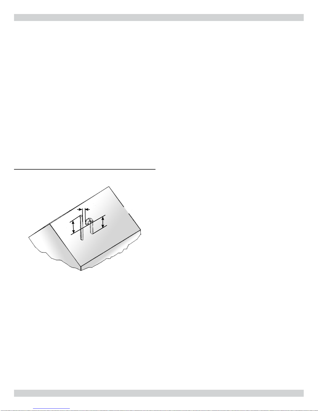
If the required clearance to grade cannot be obtained with the
“straight through” con guration, the combustion air intake pipe may
be “periscoped” up to 24” to gain extra height
VERTICAL - e combustion air termination is made up of a pair of
medium or long sweep 90° elbow pointing downward to prevent rain
from entering the combustion air intake piping. e termination
inlet must be positioned within 3” of the companion exhaust piping.
e combustion air inlet must be located a minimum of 12” above
grade, and 12” below the exhaust outlet.
(Figure 10)
(Figure 12)
Figure 12 - Standard Vertical Venting Detail
intake terminal to take advantage of the natural buoyancy of the ue
gases to help prevent re-circulation of the exhaust. (
VERTICAL - No termination tting is required if venting vertically
through a roof. e end of the exhaust pipe must be 12” higher than
the entrance of the combustion air intake terminal.
e exhaust pipe extending through the roof must extend a minimum of 18” above any obstruction within an 18” horizontal distance.
Figure 10
(Figure 12
)
)
Concentric Venting Kit
Concentric venting terminal kits may be used for this series furnace.
ey provide a means of obtaining combustion air and exhausting
products of combustion utilizing a single penetration through the
exterior wall. is can be useful when there is limited wall space
available. Kits are available in 2” and 3” sizes. If venting the 60000
Btuh model with 1½” vent material, and a concentric vent kit is
necessary, a increase coupling may be used to connect to the 2” concentric venting kit. Read the instructions supplied with the kit for
additional installation instructions and details.
ROOF TERMINATION
3" MAX.
12" MIN. ABOVE
12" MIN
ANTICIPATED
SNOW LEVEL
Exhaust
HORIZONTAL - e exhaust termination is normally a 45° elbow or
a medium or long sweep 90° elbow pointing within 45° of the downward position, away from the combustion air intake terminal.
If the required clearance to grade cannot be obtained with the
“straight through” con guration, the exhaust pipe may be “periscoped” up to 24” to gain extra height. (
ue gases may be expelled horizontally. Use the same size pipe as the
interior run and count the ttings and length as part of the total vent
length.
If winter prevailing wind conditions are variable and likely to occasionally blow ue gases back in on the combustion air intake, the
exhaust termination may be raised 18-24” above the combustion air
Figure 10
) In this case, the
Concentric Vent Termination Installation Instructions
Follow the concentric vent termination manufactures instructions
for installation of the concentric vent termination kit. ese instructions can be found by contacting the furnace manufacture. Furnace
manufacture contact information is found on the front cover of this
installation manual and operating instructions.
Location
Avoid locating the terminals where the ue gas could become stagnant and allow recirculation into the combustion air intake.
Avoid locating the terminal in locations where dripping condensate
may cause problems such as sidewalks, patios, above planters, near
windows where exhaust gases may cause fogging, etc.
Avoid locating the termination too close to shrubs and other vegetation. e condensate may stunt or kill them.
Caulk all cracks, seams or joints within a 6 foot radius of the termination.
Do not terminate under a deck unless there is adequate clearance to
prevent damage from the ue gases. A termination may be located
at the end of a patio deck. Piping running beneath the deck must be
suitably insulated and suspended in a manner to prevent condensate
22
Page 23
13 TERMINATIONS
from collecting and freezing.
Do not locate the terminal on the side of the building facing the
prevailing winter winds.
CAUTION
Improper location or installation can result in structural
damage to the building, damage to the exterior nish of
the building, or may allow recirculation or freezing of the
!
ue gases onto or into the combustion air intake.
Moisture in the ue gases condenses as it leaves the terminals. is moisture can freeze on exterior walls, so ts, and
other nearby objects. Some discoloration is to be expected.
e vent terminal should be located no fewer than 6 feet from an
inside corner formed by two exterior walls. A 10 foot distance is
recommended.
Recommended clearance for overhangs is a minimum of 1 foot vertically for each foot horizontally up to 6 feet.
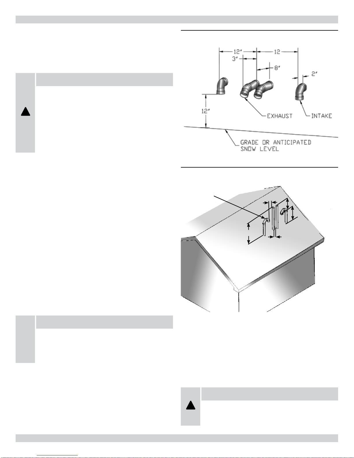
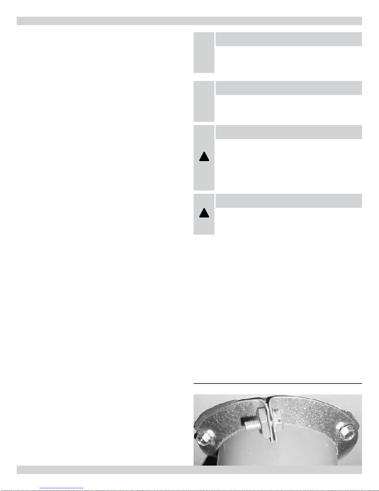
Figure 13 - Multiple Venting (Standard Horizontal)
Figure 14 - Multiple Venting (Standard Vertical
COMBUSTION
AIR INTAKE
2” PVC
3” Max.
12” Min.
12” Min. ABOVE
SNOW LEVEL
As a protection against freezing, do not expose a 3” x 2” reducing
coupling to outdoor ambient temperatures.
Any adjacent painted surfaces should be in good condition; no
cracks, peeling paint, etc. If wooden surfaces that may be periodically exposed to ue gases are present, consider treating with a sealer
such as ompson’s Water Seal®. Additional information about sealers may be obtained from the ompson’s web site at www.thompsonsonline.com.
Multiple Venting
NOTICE
IMPORTANT: When installing multiple furnaces in close
proximity, each requires dedicated combustion air and
exhaust venting.
COMMON VENTING IS PROHIBITED!!
If two of these furnaces are to be installed in close proximity, the
combustion air intake and exhaust terminations may be installed as
shown in
Figures 13 and 14
.
30” Max.
3” Max.
If more than two furnaces are being installed in close proximity, each
additional combustion air intake and exhaust termination set shall
not terminate less than 12 in (300 mm) apart.
Note:
Canadian installations of 120000 Btuh require 3 (900 mm).
WARNING
23
Recirculation of ue gases may occur causing the intake
!
pipe to freeze shut during cold weather operation if the
venting system is not installed per these guidelines.
Page 24
13 TERMINATIONS
In Canada
In addition to the general guidelines, both non-direct and direct vent
exhaust shall not terminate:
• Directly above a paved sidewalk or paved driveway which is
located between two single-family dwellings and serves both
dwellings;
• Less than 7 feet above a paved sidewalk or paved driveway
located on public property;
• Within 6 feet of a mechanical air supply inlet to any building;
• Above a meter/regulator assembly within 3 feet horizontally of
the centerline of the regulator;
• Within 6 feet of any service regulator vent outlet;
• Less than 12” above grade level or anticipated snow level;
• Within 12” of any door, window, or non-mechanical air supply inlet to any building;
• Within 12” of the combustion air inlet of any other appliance;
Note: Canadian installations of 120,000 BTU/h requires 3 .
(900 mm)
• Underneath a veranda, porch or deck, unless (a) the veranda,
porch or deck is fully open on a minimum of two sides beneath the oor, and (b) the distance between the top of the
vent termination and the underside of the veranda, porch or
deck is greater than 12”.
• Refer to Figures
17A and 17B
for terminal clearances.
In The U.S.A.
In addition to the general guidelines, in the United States, both nondirect and direct vent exhaust shall be installed in accordance with
the following:
• e clearance from the bottom of the terminal to grade shall
be 12”.
• e vent shall not terminate over public walkways or over an
area where condensate or vapor could create a nuisance or
hazard.
• e vent terminal shall be installed at least 1 foot from any
opening through which ue gases could enter a building.
• e vent terminal shall have a minimum horizontal clearance
of 4 feet from electric meters, gas meters, regulators and relief
equipment.
• Locate the vent terminal 3 feet horizontally from the vent of
any side wall vented fuel gas appliance or electric clothes dryer,
except in the case where two or more of these furnaces are
multi-vented. (See “Multiple Venting”)
NOTICE
IMPORTANT: Clean and de-burr all pipe cuts. e shavings must not be allowed to block the exhaust, combustion
air inlet or condensate drain lines.
NOTICE
IMPORTANT: If the pipe and ttings are to be other than
PVC, use the proper cleaner, primer and cement for the
dissimilar materials.
WARNING
ere must not be any openings between the blower division panel and the combustion compartment. e blower
!
compartment is under greater suction then the combustion compartment and can pull combustion air from the
burners and cause incomplete combustion and erratic
furnace operation.
WARNING
e vent must be clamped to the furnace panel using
!
the gasket and clamp provided. e intake must use the
threaded PVC connector with the gasket and lock nut.
Routing Options -
positions.
sitions. e installer must consider the following services: gas pipe,
electrical power, drain trap, intake and exhaust vents. Also consider
the air conditioning connections and drain, access to lter(s) and
access to furnace and a/c for repair. Drains and traps of furnaces
installed in spaces subjected to freezing temperature must also be
protected against freezing.
e vent must be clamped to the exterior panel(s) with the clamp
provided. Place the gasket between the clamp and the side panel.
Tighten clamp and fasten in place using the three screws provided.
e clamp should secure the vent pipe to prevent internal damage if
the vent pipe is tampered with.
e combustion air inlet tting is a 2” PVC Socket to Pipe read
adapter. Chose the intake location and open the appropriate knock
out. Install the adapter to the exterior panel using the gasket (on the
outside of the panel and the locknut on the inside of the panel.
Figures 18-25
e furnace can be installed in any of four
on the following pages show the four po-
Figure 15 -Vent Clamp and Gasket
• Refer to
FURNACE CONNECTION
Figures 17A and 17B
for terminal clearances.
24
Page 25
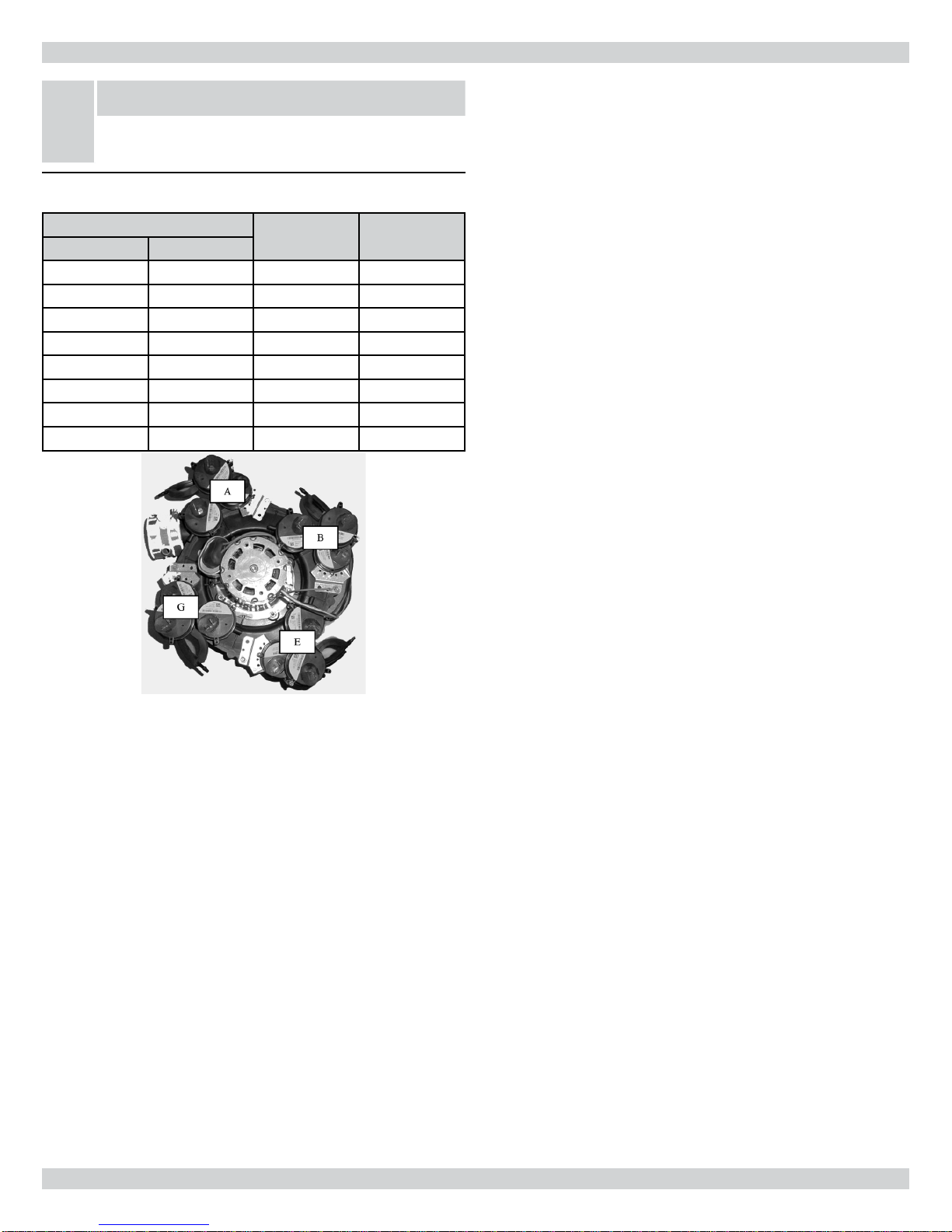
13 TERMINATIONS
NOTICE
IMPORTANT: Keep pressure switch hose above heat
exchanger drain.
Figure 16 , Table 7 - Pressure Switch Positioning
ORIENTATION
FURNACE FLUE
Down Le Y B or G
Down Right N G
Up Le N A or E
Up Right Y G
Up Vertical N A or E
Horz. Le Ve r tic a l Y E
Horz. Right Vertical N A or E
Horz. Right Right N A or E
ROTATE
INDUCER
RECOMMEND
MOUNTING
10.
Complete the venting as installation requires. If exiting the
top panel, use two street elbows to route the vent. One elbow secured to the inducer, will angle toward the front of cabinet with
the second nested inside directed towards the top panel. e
120,000 BTUH input unit will require an extension between the
inducer and the rst elbow. If exiting the side panels the pipe
can be routed straight outside the cabinet. e pipe exiting the
cabinet in any installation should be long enough to install the
vent clamp on the outside of the cabinet.
11.
Rotate the drain coupling so the drain holes are angled downward and tighten coupling bands.
12.
Tighten the vent clamp and secure in place using three screws
provided.
Always secure or support the vent and intake to the oor joists or
ra ers to avoid sagging and possible fatigue of venting materials.
is ensures proper drainage and prevents spilling the products of
combustion into the building.
e blower compartment should be completely isolated from the
burner compartment. In tight rooms with other combustion devices,
the blower compartment must be completely isolated from the room.
e combustion compartment must also be completely isolated from
the room (unless indirect vent). Sometimes the knockout tool will
punch too deep and open holes. Use caulking on the inside of the
cabinet to seal any holes. Insure that the combustion door gasket is
in good condition.
EXAMPLE: In a Horizontal Right/Vertical application (not shown), when the furnace
is horizontal, room air is exiting from the right side of furnace, and the ue is vertical
(existing from the le side panel in an up ow position), the pressure switch should be
mounted at location A or E.
Venting Installation Instructions
1.
Remove 4 inducer screws
2.
Disconnect inducer wire connection.
3.
Remove pressure switch and front manifold cover hose.
4.
Remove pressure switches if applicable.
5.
Remove inducer.
6.
Reverse the bands on the rubber drain coupling so the screws
are accessible if necessary. (Do not reverse the drain
coupling.) Con rm that directional arrow on drain coupling
point away from inducer.
7.
Remove the appropriate knock out.
8.
Reinstall the inducer in the correct orientation with 4 screws
removed in step 1.
9.
Reinstall the pressure switches so that they are above the heat
exchanger drain. See pressure switches recommended
mounting table.
25
Page 26
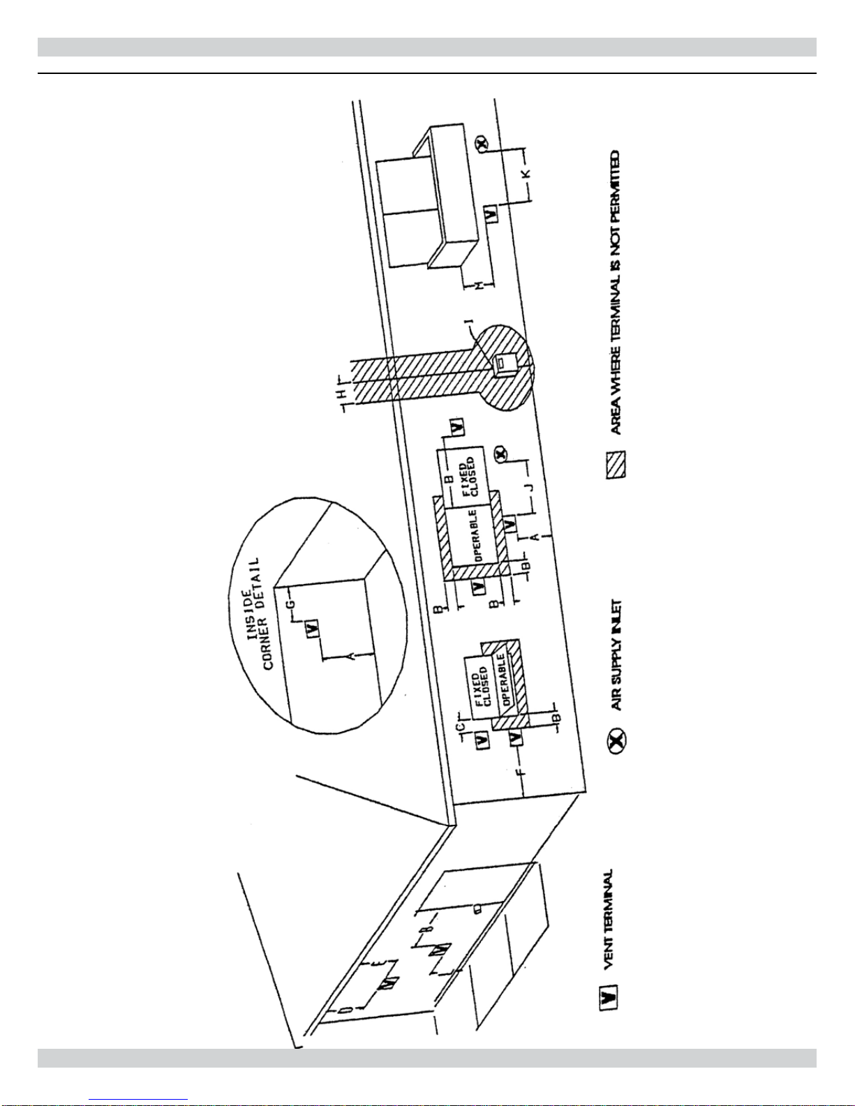
14 VENT CLEARANCES
Figure 17A & 17B- Direct Vent & Non-Direct Termination Clearances
26
Page 27
14 VENT CLEARANCES
Figure 17A - Direct Vent Termination Clearances
< 10,000 Btuh (3kW),
6 inches (15cm) for appliances
9 inches (23 cm) for appliances > 10,000 Btuh (3kW) and
*
< 50,000 Btuh (15kW),
12 inches (30 cm) for appliances > 50,000 Btuh (15kW)
*
6 inches (15 cm) for appliances < 10,000 Btuh (3kW),
9 inches (23 cm) for appliances > 10,000 Btuh (3kW) and
< 50,000 Btuh (15 kW),
12 inches (30 cm) for appliances > 50,000 Btuh (15 kW)
< 10,000 Btuh (3kW),
12 inches (30cm) 12 inches (30cm)
DIRECT VENT TERMINATION CLEARANCES
6 inches (15cm) for appliances
Clearance Canadian Installations - 1 US Installations -2
Clearance above grade, veranda, porch,
deck, or balcony
12 inches (30 cm) for appliances > 10,000 Btuh (3kW) and
< 100,000 Btuh (30kW),
36 inches (91cm) for appliances > 100,000 Btuh (30kW)
Clearance to window or door that may be
opened
*
Clearance to permanently closed window
**
6 inches (15 cm) for appliances < 10,000 Btuh (3kW),
12 inches (30 cm) for appliances > 10,000 Btuh (3kW) and
< 100,000 Btuh (30 kW),
Clearance to non-mechanical air supply
inlet to building or the combustion air inlet
36 inches (91 cm) for appliances > 100,000 Btuh (30 kW)
to any other appliance
Clearance to mechanical air supply inlet 6 feet (1.83 m) 3 feet (91 cm) above if within 10 feet (3m) horizontally
7 feet ( 2.13m) + *
12 inches (30 cm) ++ *
Clearance above paved sidewalk or paved
driveway located on public property
Clearance under veranda, porch, deck or
balcony
3 feet (91 cm) within a height 15 feet (4.5 m) above the
meter/regulator.
Vertical clearance to ventilated so t located
above the termination within a horizontal
distance of 2 feet (61 cm) from the center
line of the termination
Clearance to unventilated so t * *
Clearance to outside corner * *
Clearance to inside corner * *
Clearance to each side of center line ex-
tended above meter/regulator assembly
Clearance to service regulator vent outlet 3 feet (91 cm) *
A =
B =
C =
D =
E =
F =
G =
H =
27
I =
J =
K =
L =
M =
1 In accordance with the current CSA B149.1.1, Natural Gas and Propane Installation Code
2 In accordance with the current ANSI Z223.1/NFPA 54, National Fuel Gas Code
+ A vent shall not terminate directly above a sidewalk or paved driveway that is located between two single family dwellings and serves both dwell-
ings.
++ Permitted only if veranda, porch, deck or balcony is fully open on a minimum of two sides beneath the oor
* For clearances not speci ed in ANSI Z223.1/NFPA 54 or CSA B149.1, the following statement shall be included:
"Clearance in accordance with local installation codes and the requirements of the gas supplier and the manufacturer's installation instructions."
Page 28
14 VENT TERMINATION CLEARANCES
Figure 17B - Non-Direct Vent Termination Clearances
< 10,000 Btuh (3kW),
12 inches (30cm) 12 inches (30cm)
4 feet (1.2 m) below or to side of opening; 1 foot (30 cm)
above opening
*
*
**
*
4 feet (1.2 m) below or to side of opening; 1 foot (30 cm)
above opening
6 inches (15cm) for appliances
NON DIRECT VENT TERMINATION CLEARANCES
Clearance Canadian Installations - 1 US Installations -2
Clearance above grade, veranda, porch,
deck, or balcony
A =
12 inches (30 cm) for appliances > 10,000 Btuh (3kW) and
< 100,000 Btuh (30kW),
36 inches (91cm) for appliances > 100,000 Btuh (30kW)
Clearance to window or door that may be
opened
B =
Clearance to permanently closed window
C =
6 inches (15 cm) for appliances < 10,000 Btuh (3kW),
12 inches (30 cm) for appliances > 10,000 Btuh (3kW) and
< 100,000 Btuh (30 kW),
Clearance to non-mechanical air supply
inlet to building or the combustion air inlet
J =
36 inches (91 cm) for appliances > 100,000 Btuh (30 kW)
to any other appliance
Clearance to mechanical air supply inlet 6 feet (1.83 m) 3 feet (91 cm) above if within 10 feet (3m) horizontally
K =
7 feet ( 2.13m) + 7 feet (2.13m)
Clearance above paved sidewalk or paved
driveway located on public property
Clearance under veranda, porch, deck or
L =
12 inches (30 cm) ++ *
balcony
M =
1 In accordance with the current CSA B149.1.1, Natural Gas and Propane Installation Code
2 In accordance with the current ANSI Z223.1/NFPA 54, National Fuel Gas Code
+ A vent shall not terminate directly above a sidewalk or paved driveway that is located between two single family dwellings and serves both dwell-
ings.
++ Permitted only if veranda, porch, deck or balcony is fully open on a minimum of two sides beneath the oor
* For clearances not speci ed in ANSI Z223.1/NFPA 54 or CSA B149.1, the following statement shall be included:
"Clearance in accordance with local installation codes and the requirements of the gas supplier and the manufacturer's installation instructions."
3 feet (91 cm) within a height 15 feet (4.5 m) above the
meter/regulator.
Vertical clearance to ventilated so t located
above the termination within a horizontal
distance of 2 feet (61 cm) from the center
line of the termination
Clearance to unventilated so t * *
Clearance to outside corner * *
Clearance to inside corner * *
Clearance to each side of center line ex-
tended above meter/regulator assembly
Clearance to service regulator vent outlet 3 feet (91 cm) *
D =
E =
F =
G =
H =
I =
28
Page 29
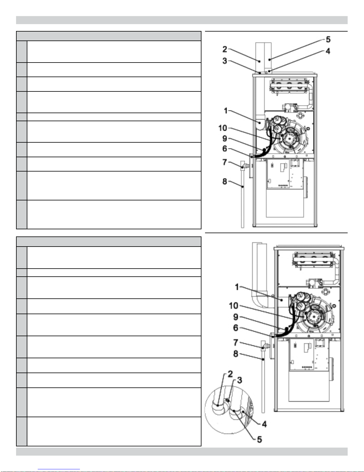
15 VENT AND DRAINING OPTIONS UPFLOW
Instructions for Up ow with Top Venting
Connect two (2) 2” Street elbows (in parts bag) to the coupler on the exhauster
1.
(Add 2” nipple for 120K BTU units). Ensure exhauster coupler drain outlet is
facing downward 15°.
Remove 2.5” knockout and connect 2” vent pipe ( eld supplied). If using 1.5” or
2.
3” vent, make transition as close as possible to the unit and on a vertical section.
Install gasket on panel then vent bracket, use three (3) self tapping screws (all
3.
parts from parts bag).
Remove 2.5” knockout and connect 2” air intake coupler with gasket on the out-
4.
side of unit using the 2” nut (all parts from parts bag). If using 1.5” or 3” intake,
make transition as close as possible to the unit and on a vertical section.
Connect 2” intake pipe ( eld supplied)
5.
Remove two (2) 7/8” knockouts and install the condensate trap with gasket,
6.
hold in place with two (2) screws (all parts supplied in parts bag). **Condensate
trap can be placed on either side of unit**
**IMPORTANT** Connect a 1/2” tee tting ( eld supplied) to the outlet of the
7.
condensate trap.
Connect 1/2” drain tube ( eld supplied) and route to oor drain or condensate
8.
pump.
Connect one end of the 5/8” tubing (in parts bag) to the drain on the front
9.
manifold cover, route to the larger outlet on the condensate trap, cut excess tube
and hold in place with supplied hose clamps. Tubing should slope towards drain
trap with no sags.
Connect one end of the 1/2” tubing (in parts bag) to the lower drain outlet on
10.
the exhauster coupler, route to the smaller inlet on the condensate trap, cut
excess tube and hold in place with supplied hose clamps. Tubing should slope
towards drain trap with no sags.
Figure 18 -
Up ow with Top Venting
Instructions for Up ow with Left Side Venting
Remove 2.5” knockout and connect 2” nipple approximately
1.
7” long ( eld supplied) to the coupler on the exhauster. Ensure exhauster coupler drain outlet is facing downward 15°.
Connect 2” elbow and 2” vent pipe ( eld supplied)
2.
Install gasket on panel then vent bracket, use three (3) self
3.
tapping screws (all parts from parts bag.) If using 1.5” or 3” vent, make transition as close as possible to the unit and on a vertical section.
Remove 2.5” knockout and connect 2” air intake coupler with gasket on the
4.
outside of unit, use the 2” nut to fasten this (all parts from parts bag).
Connect 2” street elbow (from parts bag) and intake pipe ( eld supplied). If
5.
using 1.5” or 3” intake, make transition as close as possible to the unit and on a
vertical section.
Remove two (2) 7/8” knockouts and install the condensate trap with gasket,
6.
hold in place with two (2) screws (all parts supplied in parts bag). **Condensate
trap can be placed on either side of unit**
**IMPORTANT** Connect a 1/2” tee tting ( eld supplied) to the outlet of the
7.
condensate trap.
Connect 1/2” drain tube ( eld supplied) and route to oor drain or condensate
8.
pump.
Connect one end of the 5/8” tubing (in parts bag) to the drain on the front
9.
manifold cover, route to the larger outlet on the condensate trap, cut excess tube
and hold in place with supplied hose clamps. Tubing should slope towards drain
trap with no sags.
Connect one end of the 1/2” tubing (in parts bag) to the lower drain outlet on
10.
the exhauster coupler, route to the smaller inlet on the condensate trap, cut
excess tube and hold in place with supplied hose clamps. Tubing should slope
towards drain trap with no sags.
29
Figure 19 -
Up ow with Left Side Venting
Page 30
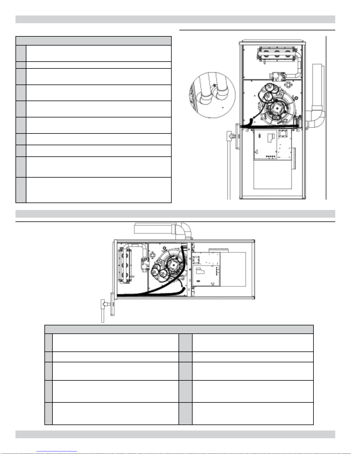
15 VENT AND DRAINING OPTION UPFLOW
Instructions for Up ow with Right Side Venting
1.
Remove 2.5” knockout and connect 2” nipple approximately
2.5” long ( eld supplied) to the coupler on the exhauster.
Ensure exhauster coupler drain outlet is facing downward 15°.
2.
Connect 2” elbow and 2” vent pipe ( eld supplied)
3.
Install gasket on panel then vent bracket, use three (3) self tapping
screws (all parts from parts bag). If using 1.5” or 3” vent, make transition as close as possible to the unit and on a vertical section.
4.
Remove 2.5” knockout and connect 2” air intake coupler with gasket
on the outside of unit, use the 2” nut to fasten this (all parts from
parts bag).
5.
Connect 2” elbow and intake pipe ( eld supplied). If using 1.5” or
3” intake, make transition as close as possible to the unit and on a
vertical section.
6.
Remove two (2) 7/8” knockouts and install the condensate trap with
gasket, hold in place with two (2) screws (all parts supplied in parts
bag). **Condensate trap can be placed on either side of unit**
7.
**IMPORTANT** Connect a 1/2” tee tting ( eld supplied) to the
outlet of the condensate trap.
8.
Connect 1/2” drain tube ( eld supplied) and route to oor drain or
condensate pump.
9.
Connect one end of the 5/8” tubing (in parts bag) to the drain on
the front manifold cover, route to the larger outlet on the condensate
trap, cut excess tube and hold in place with supplied hose clamps.
Tubing should slope towards drain trap with no sags.
10.
Connect one end of the 1/2” tubing (in parts bag) to the lowest drain
outlet on the exhauster coupler, route to the smaller inlet
on the condensate trap, cut excess tube and hold in place with supplied hose clamps. Tubing should slope towards drain trap
with no sags.
Figure 20 -
Up ow with Right Side Venting
Figure 21 -
15 VENT AND DRAINING OPTION HORIZONTAL LEFT
Horizontal Left with Top Venting
Instructions for Horizontal Left with Top Venting
1.
Remove 2.5” knockout and connect 2” nipple approximately
2.5” long ( eld supplied) to the coupler on the exhauster.
Ensure exhauster coupler drain outlet is facing downward
15°.
2.
Connect 2” elbow and 2” vent pipe ( eld supplied). 7. **IMPORTANT** Connect a 1/2” tee tting ( eld sup-
3.
Install gasket on panel then vent bracket, use three (3) self
tapping screws (all parts from parts bag). If using 1.5” or 3”
vent, make transition as close as possible to the unit and on
a vertical section.
4.
Remove 2.5” knockout and connect 2” air intake coupler
with gasket on the outside of unit, use the 2” nut to fasten
this (all parts from parts bag). **Refer to page 26 for inducer orientation**
5.
Connect 2” street elbow (from parts bag) and intake pipe
( eld supplied). If using 1.5” or 3” intake, make transition as
close as possible to the unit and on a vertical section.
6. Remove two (2) 7/8” knockouts and install the condensate trap bracket by removing and reusing the 2 top panel
screws, install condensate trap with gasket, hold in place
with 2 screws (all parts supplied in parts bag).
plied) to the outlet of the condensate trap.
8. Connect 1/2” drain tube ( eld supplied) and route to
oor drain or condensate pump.
9. Connect one end of the 5/8” tubing (in parts bag) to the
drain on the front manifold cover, route to the larger
outlet on the condensate trap, cut excess tube and hold
in place with supplied hose clamps. Tubing should slope
towards drain trap with no sags.
10. Connect one end of the 1/2” tubing (in parts bag) to the
lower drain outlet on the exhauster coupler, route to the
smaller inlet on the condensate trap, cut excess tube and
hold in place with supplied hose clamps. Tubing should
slope towards drain trap with no sags.
30
Page 31
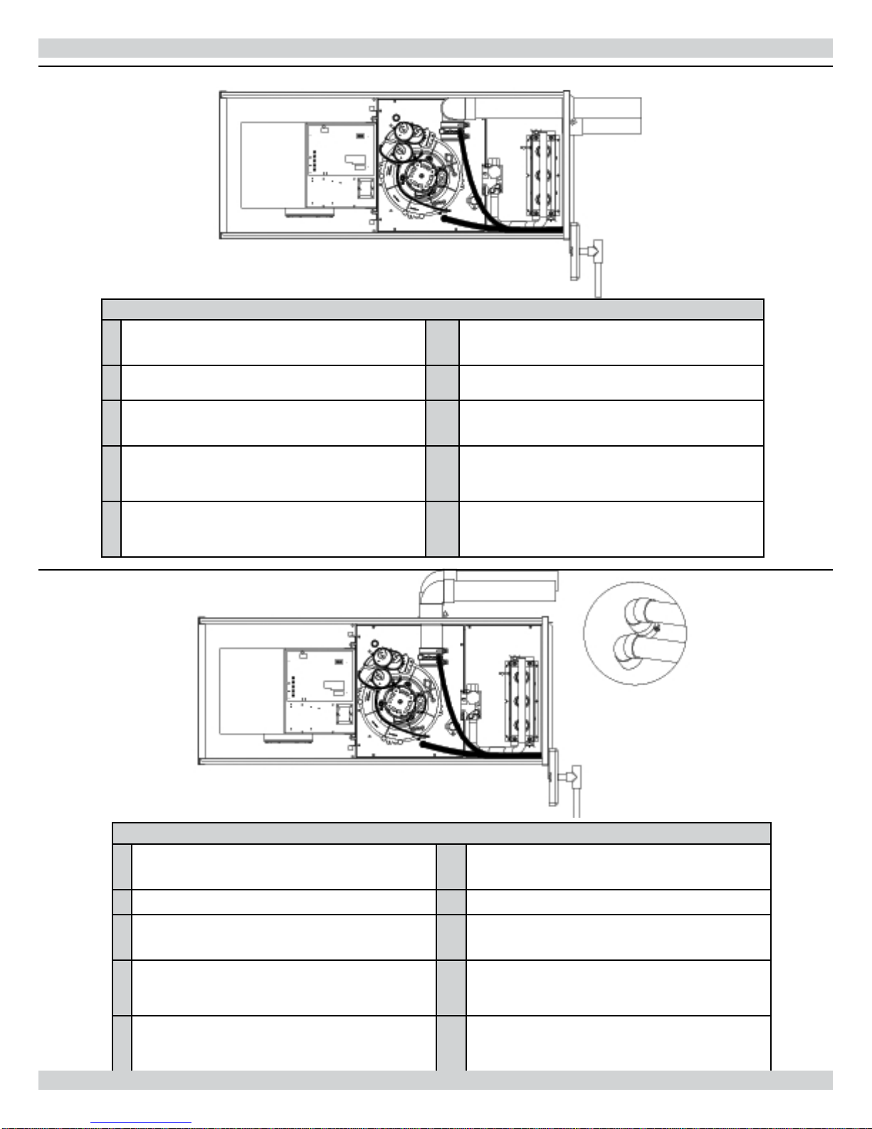
15 VENT AND DRAINING OPTION HORIZONTAL RIGHT
Figure 22 -
1.
2.
3.
4.
5.
Horizontal Right with Right Side Venting
Instructions for Horizontal Right with Right Side Venting
Connect two (2) 2” Street elbows (in parts bag) to the
coupler on the exhauster (Add 2” nipple for 120K BTU
units). Ensure exhauster coupler drain outlet is facing
downward 15°.
Remove 2.5” knockout and connect 2” vent pipe ( eld
supplied). If using 1.5” or 3” vent, make transition as close
as possible to the unit and on a vertical section.
Install gasket on panel then vent bracket, use three (3) self
tapping screws (all parts from parts bag). If using 1.5” or
3” vent, make transition as close as possible to the unit
and on a vertical section.
Remove 2.5” knockout and connect 2” air intake coupler
with gasket on the outside of unit, use the 2” nut to fasten
this (all parts from parts bag). **Refer to page 26 for
inducer orientation**
Connect 2” street elbow (from parts bag) and intake pipe
( eld supplied). If using 1.5” or 3” intake, make transition
as close as possible to the unit and on a vertical section.
6. Remove two (2) 7/8” knockouts and install the condensate trap bracket by removing and reusing the 2 top panel
screws, install condensate trap with gasket, hold in place
with 2 screws (all parts supplied in parts bag).
7. **IMPORTANT** Connect a 1/2” tee tting ( eld supplied) to the outlet of the condensate trap.
8. Connect 1/2” drain tube ( eld supplied) and route to oor
drain or condensate pump.
9. Connect one end of the 5/8” tubing (in parts bag) to the
drain on the front manifold cover, route to the larger
outlet on the condensate trap, cut excess tube and hold
in place with supplied hose clamps. Tubing should slope
towards drain trap with no sags.
10. Connect one end of the 1/2” tubing (in parts bag) to the
lower drain outlet on the exhauster coupling, route to the
smaller inlet on the condensate trap, cut excess tube and
hold in place with supplied hose clamps. Tubing should
slope towards drain trap with no sags.
Figure 23 - Horizontal Right with Top Venting
Instructions for Horizontal Right with Top Venting
1.
Remove 2.5” knockout and connect 2” nipple approximately 7” long ( eld supplied) to the coupler on the
exhauster. Ensure exhauster coupler outlet is facing right
side approximately 15°.
2.
Connect 2” elbow and 2” vent pipe ( eld supplied). 7. **IMPORTANT** Connect a 1/2” tee tting ( eld sup-
3.
Install gasket on panel then vent bracket, use three (3) self
tapping screws (all parts from parts bag). If using 1.5” or
3” vent, make transition as close as possible to the unit
and on a vertical section.
4.
Remove 2.5” knockout and connect 2” air intake coupler
with gasket on the outside of unit, use the 2” nut to fasten
this (all parts from parts bag). **Refer to page 26 for
inducer orientation**
5.
Connect 2” street elbow (from parts bag) and intake pipe
( eld supplied). If using 1.5” or 3” intake, make transition
as close as possible to the unit and on a vertical section.
6. Remove two (2) 7/8” knockouts and install the condensate trap bracket by removing and reusing the 2 top panel
screws, install condensate trap with gasket, hold in place
with 2 screws (all parts supplied in parts bag).
plied) to the outlet of the condensate trap.
8. Connect 1/2” drain tube ( eld supplied) and route to oor
drain or condensate pump.
9. Connect one end of the 5/8” tubing (in parts bag) to the
drain on the front manifold cover, route to the larger
outlet on the condensate trap, cut excess tube and hold
in place with supplied hose clamps. Tubing should slope
towards drain trap with no sags.
10. Connect one end of the 1/2” tubing (in parts bag) to the
lower drain outlet on the exhauster coupler, route to the
smaller inlet on the condensate trap, cut excess tube and
hold in place with supplied hose clamps. Tubing should
slope towards drain trap with no sags.
31
Page 32
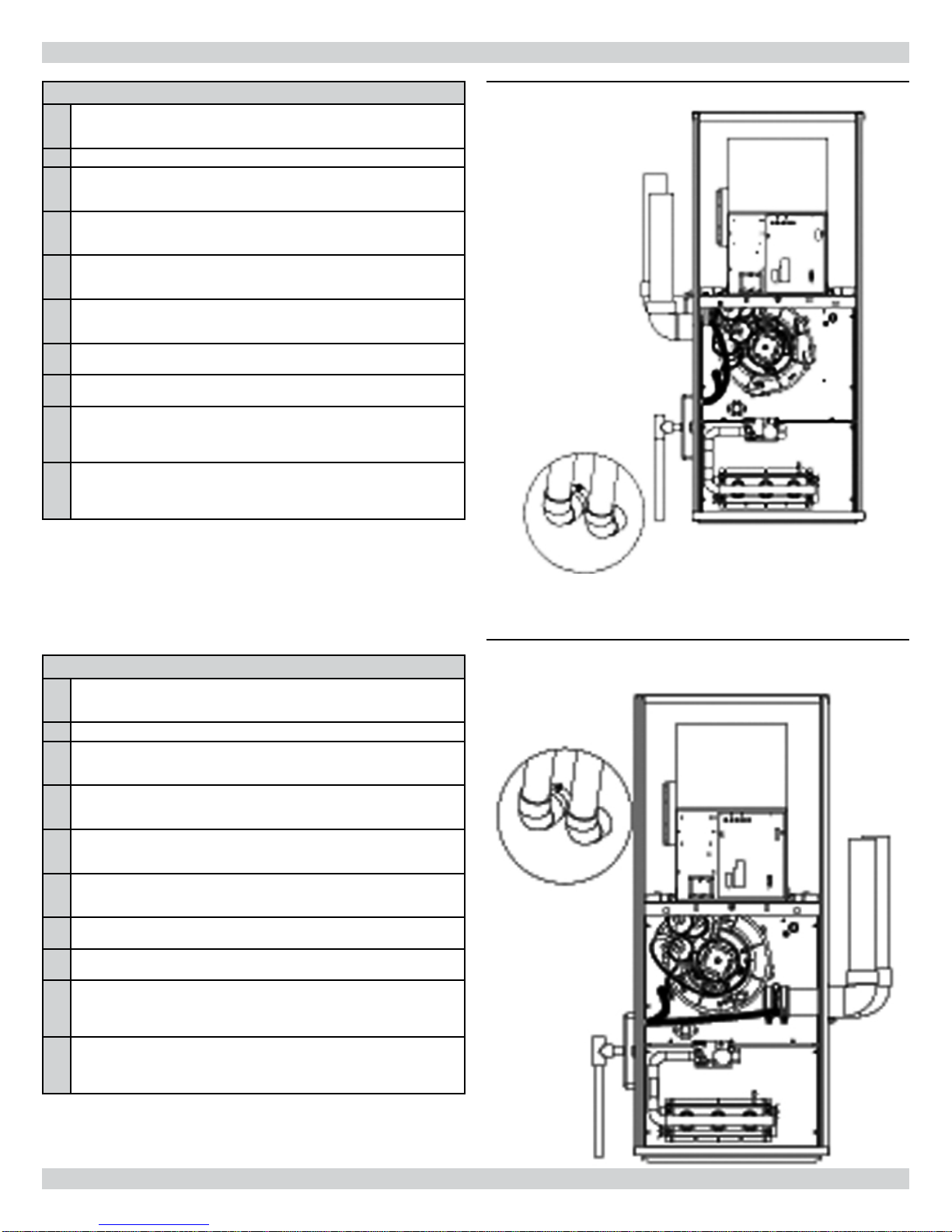
15 VENT AND DRAINING OPTION DOWNFLOW
Instructions for Down ow with Left Side Venting
1.
Remove 2.5” knockout and connect 2” nipple approximately
2.5” long ( eld supplied) to the coupler on the exhauster.
Ensure exhauster coupler drain outlet is facing downward 15°.
2.
Connect 2” elbow and 2” vent pipe ( eld supplied)
3.
Install gasket on panel then vent bracket, use three (3) self tapping
screws (all parts from parts bag). If using 1.5” or 3” vent, make
transition as close as possible to the unit and on a vertical section.
4.
Remove 2.5” knockout and connect 2” air intake coupler with gasket
on the outside of unit, use the 2” nut to fasten this (all parts from
parts bag).
5.
Connect 2” street elbow (from parts bag) and intake pipe ( eld supplied). If using 1.5” or 3” intake, make transition as close as
possible to the unit and on a vertical section.
6.
Remove two (2) 7/8” knockouts and install the condensate trap with
gasket, hold in place with two (2) screws (all parts supplied in parts
bag). **Condensate trap can be placed on either side of unit**
7.
**IMPORTANT** Connect a 1/2” tee tting ( eld supplied) to the
outlet of the condensate trap.
8.
Connect 1/2” drain tube ( eld supplied) and route to oor drain or
condensate pump.
9.
Connect one end of the 5/8” tubing (in parts bag) to the drain on
the front manifold cover, route to the larger outlet on the condensate
trap, cut excess tube and hold in place with supplied hose clamps.
Tubing should slope towards drain trap with no sags.
10.
Connect one end of the 1/2” tubing (in parts bag) to the lower drain
outlet on the exhauster coupler, route to the smaller inlet on the
condensate trap, cut excess tube and hold in place with supplied hose
clamps. Tubing should slope towards drain trap with no sags.
Figure 24 -
Down ow with Left Side Venting
Instructions for Down ow with Right Side Venting
1.
Remove 2.5” knockout and connect 2” nipple approximately 7” long
( eld supplied) to the coupler on the exhauster. Ensure exhauster
coupler drain outlet is facing downward 15°.
2.
Connect 2” elbow and 2” vent pipe ( eld supplied).
3.
Install gasket on panel then vent bracket, use three (3) self tapping
screws (all parts from parts bag). If using 1.5” or 3” vent, make
transition as close as possible to the unit and on a vertical section.
4.
Remove 2.5” knockout and connect 2” air intake coupler with gasket
on the outside of unit, use the 2” nut to fasten this (all parts from
parts bag).
5.
Connect 2” street elbow (from parts bag) and intake pipe ( eld supplied). If using 1.5” or 3” intake, make transition as close as
possible to the unit and on a vertical section.
6.
Remove two (2) 7/8” knockouts and install the condensate trap with
gasket, hold in place with two (2) screws (all parts supplied in parts
bag). **Condensate trap can be placed on either side of unit**
7.
**IMPORTANT** Connect a 1/2” tee tting ( eld supplied) to the
outlet of the condensate trap.
8.
Connect 1/2” drain tube ( eld supplied) and route to oor drain or
condensate pump.
9.
Connect one end of the 5/8” tubing (in parts bag) to the drain on
the front manifold cover, route to the larger outlet on the condensate
trap, cut excess tube and hold in place with supplied hose clamps.
Tubing should slope towards drain trap with no sags.
10.
Connect one end of the 1/2” tubing (in parts bag) to the lower drain
outlet on the exhauster coupler, route to the smaller inlet on the
condensate trap, cut excess tube and hold in place with supplied hose
clamps. Tubing should slope towards drain trap with no sags.
Figure 25 -
Down ow with Right Side Venting
32
Page 33
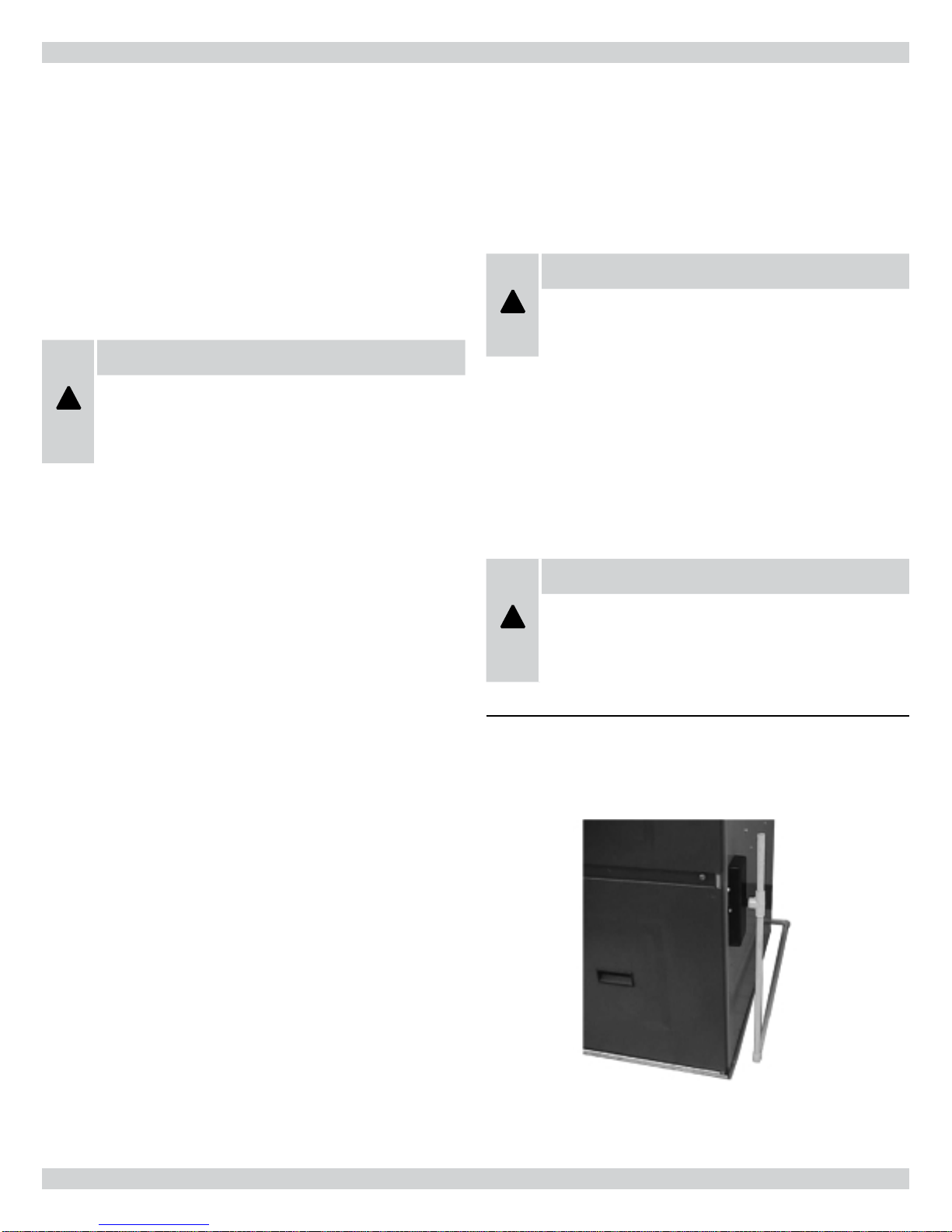
16 CONDENSATE DRAINS
e furnace may condense as much as a 4½ pounds of water per
hour (approximately 2 imperial quarts, 2½ U.S. quarts or 2¼ liters).
It is necessary to make provisions for draining the condensate away.
e furnace is supplied with a drain trap assembly. See
-25
for possible locations of the drain trap.
e drain coupling on the inducer will work better if the drain holes
are pointed down about 15 degrees. e drain hose supplied with the
furnace is long enough to reach either side panel; however, it must be
cut near the blower division panel. is is to prevent kinking in the
drain lines.
CAUTION
e two inlets to the drain trap are for vent pipe and con-
!
densate collection. e vent pipe inlet is smaller than the
condensate collection inlet. Ensure that the drain hoses are
properly connected.
Figures 18
Drain Hose Installation
1.
Select a drain trap location suitable for the orientation of the
furnace and remove the corresponding knockouts. See
18-25
.
Figures
6.
Cut the formed vent drain tube to the required length if necessary, and slide over inlet on the drain trap (smaller diameter
inlet hole). Fasten by tightening the tube clamp approximately
⅛” from the end of the tube.
7.
All drain tubes must slope towards the drain trap.
CAUTION
Ensure that drain hoses do not create traps prior to the
!
condensate trap assembly. A secondary trap will cause intermittent operation due to the pressure switches opening.
Drain Piping
Condensate from the outlet of the drain trap assembly must be
conveyed to a oor drain, sump pit, or, if these are unavailable,
to a condensate pump. If using a condensate pump, be sure that
it is approved for furnace condensate.
CAUTION
2.
A x the drain trap assembly to the exterior of the side panel
when the furnace is up ow or down ow using two screws
provided. For horizontal positions the installer will need to use
the mounting bracket supplied and secure the bracket to the top
panel. Remove two top panel screws and fasten bracket to top
panel with removed screws. Secure trap assembly using screws
provided to the mounting bracket.
3.
Slide the short end of the 5/8” formed tube over the appropriate condensate outlet on the front manifold cover, and fasten
by tightening the tube clamp approximately ⅛” from the end of
the tube.
4.
Cut the formed drain tube to the required length if necessary, and slide tube over the condensate inlet on the drain trap
(larger diameter inlet hole). Fasten by tightening the tube clamp
approximately ⅛” from the end of the tube.
5.
Rotate exhauster coupling 15 degrees downwards, and remove
the yellow cap over the lowest vent drain outlet. Slide the short
end of the ½” drain tube on the exhauster coupling drain.
Fasten by tightening the tube clamp approximately ⅛” from the
end of the tube.
Do not drain the condensate outdoors. Do not run the
!
condensate line through areas where freezing might occur.
Freezing of condensate can result in erratic furnace operation and in property damage.
Figure 26 - Condensate Trap/Condensate Drainage With
Vent
33
Page 34
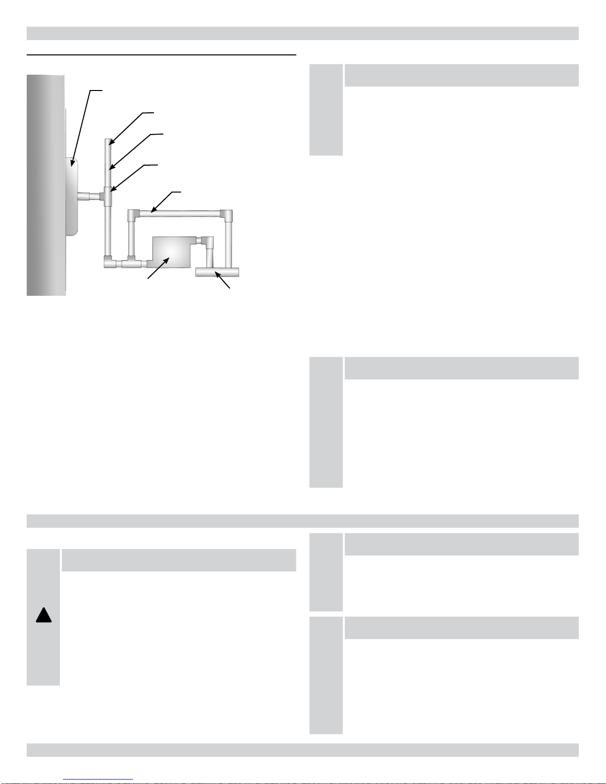
Figure 27 - Condensate Bypass
OLSEN DRAIN TRAP
ASM
VENT
VENT HEIGHT MUST BE 1"
ABOVE RECOVERY COIL
1/2" PIPE
G95V
& FITTINGS
UNIT
16 CONDENSATE DRAINS
NEUTRALIZER BYPASS
NOTICE
IMPORTANT: If an air conditioning evaporator coil drain
is to share the furnace drain line, it should be connected
with a tee tting downstream from the trap. Do not connect the evaporator coil condensate drain upstream of the
furnace drain trap assembly.
Condensate Neutralizers
Some local codes may require the use of a condensate neutralizer. If
the furnace condensate is to be routed to a septic system, it may be
advisable to use a condensate neutralizer.
CONDENSATE NEUTRALIZER
IF REQUIRED
DRAIN
e condensate drainage con guration requires a vent. It takes less
than a one inch rise anywhere along the horizontal route of the drain
tube to create a vapor lock, which will prevent condensate from
draining away freely, and result in erratic furnace operation.
A typical con guration would be to cement the side branch of a ½”
PVC tee to the drain trap assembly outlet, with the end branches
oriented vertically. (
Figure 27
)
A 1” piece of ½” PVC pipe cemented to the upper end branch will
serve as a vent, which will prevent the creation of a vapor lock,
and serve as an over ow in the event that the drain line becomes
blocked. A similarly sized piece of pipe cemented to the lower end
branch will permit connection to the condensate outlet with ⅝” ID
/ ⅞” OD exible tubing, or the condensate may be piped entirely in
PVC to the oor drain/sump/condensate pump.
17 GAS SUPPLY AND PIPING
Gas Supply
WARNING
THIS FURNACE IS FACTORY EQUIPPED TO BURN
NATURAL GAS ONLY.
CONVERSION TO LP GAS REQUIRES SPECIAL NATU-
!
RAL GAS TO LP CONVERSION KIT.
FAILURE TO USE THE PROPER CONVERSION KIT
CAN CAUSE FIRE, EXPLOSION, CARBON MONOXIDE POISONING, PROPERTY DAMAGE, PERSONAL
INJURY OR LOSS OF LIFE.
Condensate neutralizers such as the Ward Industries 90+ Neutralizer
are available through heating supply wholesalers.
When condensate neutralizers are used, it is advisable to install it
with an over ow bypass tube. (
Figure 27)
NOTICE
IMPORTANT: e condensate drain trap assembly should
be full of water before starting the furnace. To ll the condensate drain trap assembly, temporarily remove the vent
drain hose from the induced blower assembly elbow/drain
tting, and pour approximately one cup of water down the
hose. Water will begin running out the condensate drain
trap outlet when it is full. Refasten the vent drain hose to
the induced blower assembly elbow/drain tting.
NOTICE
IMPORTANT: Conversion of this furnace requires
specialized equipment. Conversion must be completed
by a trained and quali ed installer, service agency or gas
supplier.
NOTICE
IMPORTANT: Connect this furnace only to gas supplied
by a commercial utility or supplier. Private gas wells do not
generally provide gas with consistent, uniform and predictable heating values and densities. Many non-commercial wells contain impurities such as sulphur, which may
damage the furnace. is furnace cannot operate properly
or safely using fuels outside normal commercial standards.
34
Page 35
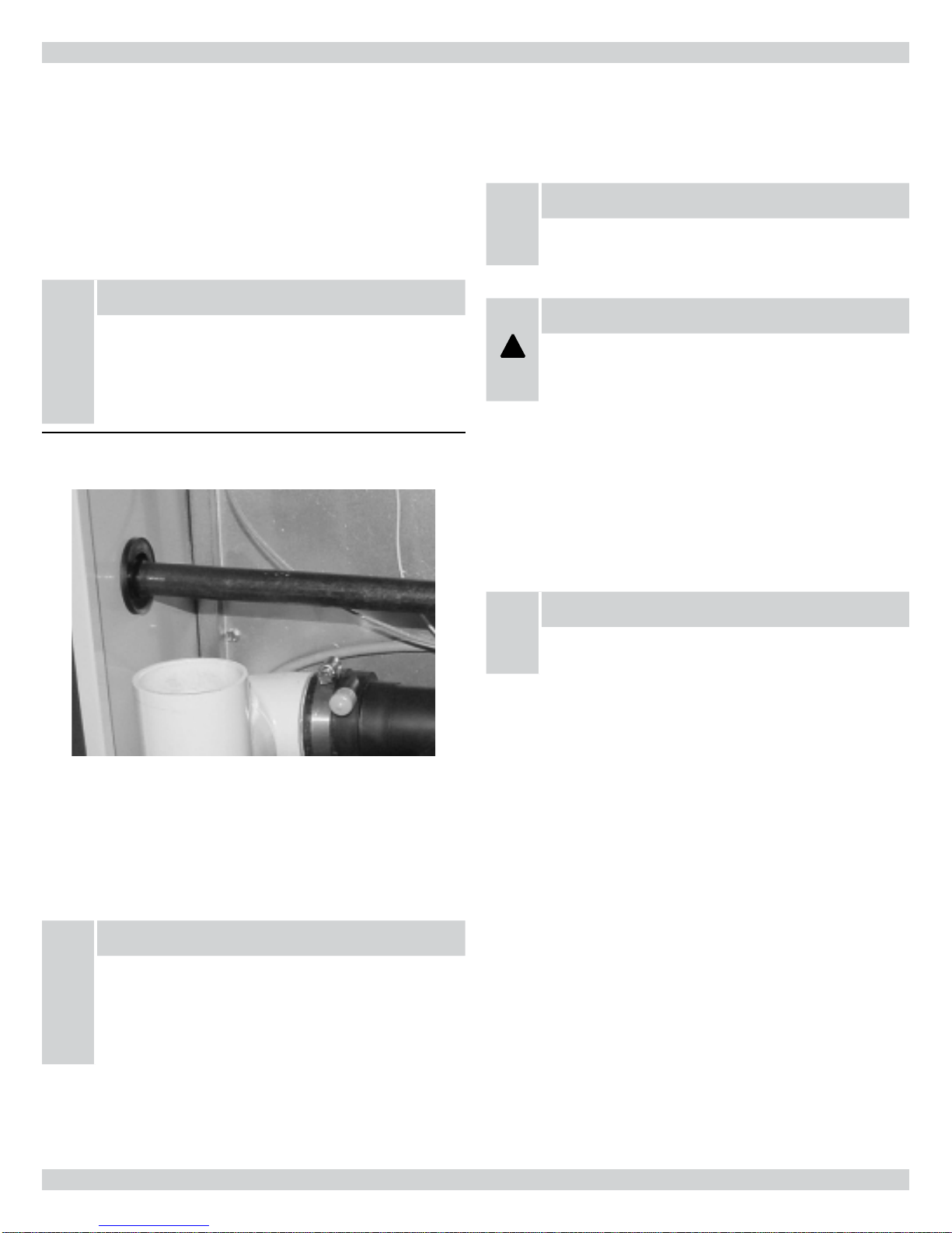
17 GAS SUPPLY AND PIPING
Gas Piping
In Canada, the gas piping should be installed in accordance with
CAN/CGA-B149.1 and 2, and in accordance with any local codes.
In the United States, the gas piping should be installed in accordance
with NFPA 54 / ANSI Z223.1 and any local codes.
If local codes allow the use of a exible gas appliance connector,
always use a new listed connector. Do not use a connector, which has
previously serviced another gas appliance.
NOTICE
IMPORTANT: To maintain a good seal in the burner area,
the gas piping through the side panel into the furnace
must be ½” A53 black iron pipe. e pipe passes through
a special rubber grommet that is custom manufactured to
seal tightly around the gas pipe.
Figure 28 - Furnace Gas Pipe Connections (Note Rubber
Grommet)
Install a manual gas shut-o valve and dirt pocket as close to the
furnace as possible. Some local codes call for the manual gas shut-o
valve to be located between 4 to 5 feet above oor level to prevent
tampering by small children. Ensure that the valve is readily accessible.
NOTICE
IMPORTANT: Ensure that the manual shut-o valve and
gas valve are not subjected to high pressures.
WARNING
Indicates an imminently hazardous situation which, if not
!
avoided, may result in death, serious injury or substantial
property damage.
Gas Inlet Pressure
e natural gas inlet supply pressure should be 5” to 7” w.c. (7” w.c.
recommended). e LP gas inlet supply pressure should be 11” to
14” w.c. (12” w.c. recommended). ese pressures must be maintained while all other gas red appliances are operating at maximum
conditions.
e gas piping may enter the furnace from either side. Once the
routing of the gas pipe is determined, select and remove the applicable knockout and install the grommet within the hole.
Install a BMI ground joint union between the gas valve and the side
panel to allow easy removal of the burner for service purposes.
NOTICE
IMPORTANT: Always use a backup wrench to prevent
twisting of the control assembly and gas valve. Any strains
on the gas valve can a ect positioning of the ori ces
relative to the burners. is could result in faulty burner
operation.
NOTICE
IMPORTANT: Do not exceed 14” w.c. inlet pressure with
either fuel.
e gas valve has two adjustable internal
regulators for controlling burner manifold pressure. Burner manifold high re and low re pressures are listed on the furnace rating
plate.
Leak Testing
All new gas piping installations should be pressure tested as speci ed
by CAN/CGA-B149.1 & 2, or NFPA 54 ANSI Z223.1 or ANSI/NFPA
58, “Standard for the Storage and Handling of Lique ed Petroleum
Gases.”
Gas piping that has not been pressure tested, from the manual
shut-o valve to the furnace gas valve for example, should be leak
tested using an electronic combustible gas detector, a commercially
prepared leak detector, or other locally approved method. A leak
detector solution can be prepared by mixing a small quantity of dish
detergent with water and daubing it onto the gas piping, especially
the joints.
35
Page 36
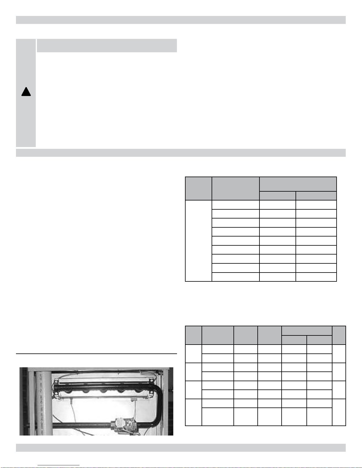
Purging Gas Lines
NEVER PURGE A GAS LINE INTO THE COMBUSTION CHAMBER.
NEVER USE A MATCH, TAPER, CIGARETTE LIGHTER, FLAME OR ANY OTHER IGNITION SOURCE TO
!
CHECK FOR LEAKS IN A GAS LINE.
FAILURE TO ADHERE TO THIS WARNING CAN
CAUSE A FIRE OR EXPLOSION RESULTING IN PROPERTY DAMAGE, PERSONAL INJURY, OR LOSS OF
LIFE.
17 GAS SUPPLY AND PIPING
WARNING
18 CONVERSIONS
HIGH ALTITUDE: In Canada, the furnace may be converted for
high altitude (2000-4500 feet) by changing the burner ori ces. e
Conversion Kit part number 550001641 contains both natural gas
and LP gas ori ces. (
Table 9
)
In the United States, the modi cations for high altitude are based on
a 2% reduction of input capacity for every 1000 feet above 2000 feet
above sea level.
Table 8
illustrates the impact of altitude for selected
elevations. Consult with local fuel suppliers or authorities to determine local regulations or customs.
NATURAL TO LP GAS: is series furnace is manufactured as a
natural gas (sea level) appliance that may be converted to LP gas
through use of the Conversion Kit part number 550001648. is
kit contains the ori ces needed for all models, the regulator springs
for the gas valve, and a label to a x adjacent to the appliance rating
plate to alert subsequent service technicians of the conversion.
LP TO NATURAL GAS: Although the furnace is manufactured
initially as a natural gas appliance, if, a er an LP gas conversion it
becomes necessary to convert back to natural gas and the original
parts are unavailable, e Conversion Kit part number 550001816
may be obtained.
Figure 29 - Inshot Burner Assembly
TABLE 8 - HIGH ALTITUDE SPECIFICATIONS
(U.S.A.)
MODEL ALTITUDE (FT)
0-2000 45 55
2000-3000 48 56
3000-4000 49 57
4000-5000 50 58
All
† Gas input ratings are certi ed for elevations to 2000 . For elevations above
2000 , reduce ratings 2% for each 1000 above sea level.
In Canada, derate the unit 5% for elevations from 2000 to 4000 above sea
level.
5000-6000 51 60
6000-7000 52 61
7000-8000 53 62
8000-9000 54 63
9000-10000 55 65
ORIFICE SIZE (DMS)
NATURAL LP GAS
TABLE 9- HIGH ALTITUDE SPECIFICATIONS (CANADA)
MOD-ELALTITUDE
(FT)
60
80
100
120
0 - 2000 60000 57000 45 55
2000 - 4500 54000 51300 46 56
0 - 2000 80000 76000 45 55
2000 - 4500 72000 68400 46 56
0 - 2000 100000 95000 45 55
2000 - 4500 90000 85500 46 56
0 - 2000 120000 114000 45 55
2000 - 4500 108000 102600 46 56
INPUT
BTU/HR
OUTPUT
BTU/HR
ORIFICE SIZE (DMS)
NATURAL LP GAS
QTY.
3
4
5
6
† Gas input ratings are certi ed for elevations to 2000 . For elevations
above 2000 , reduce ratings 2% for each 1000 above sea level.
In Canada, derate the unit 5% for elevations from 2000 to 4000
above sea level.
36
Page 37
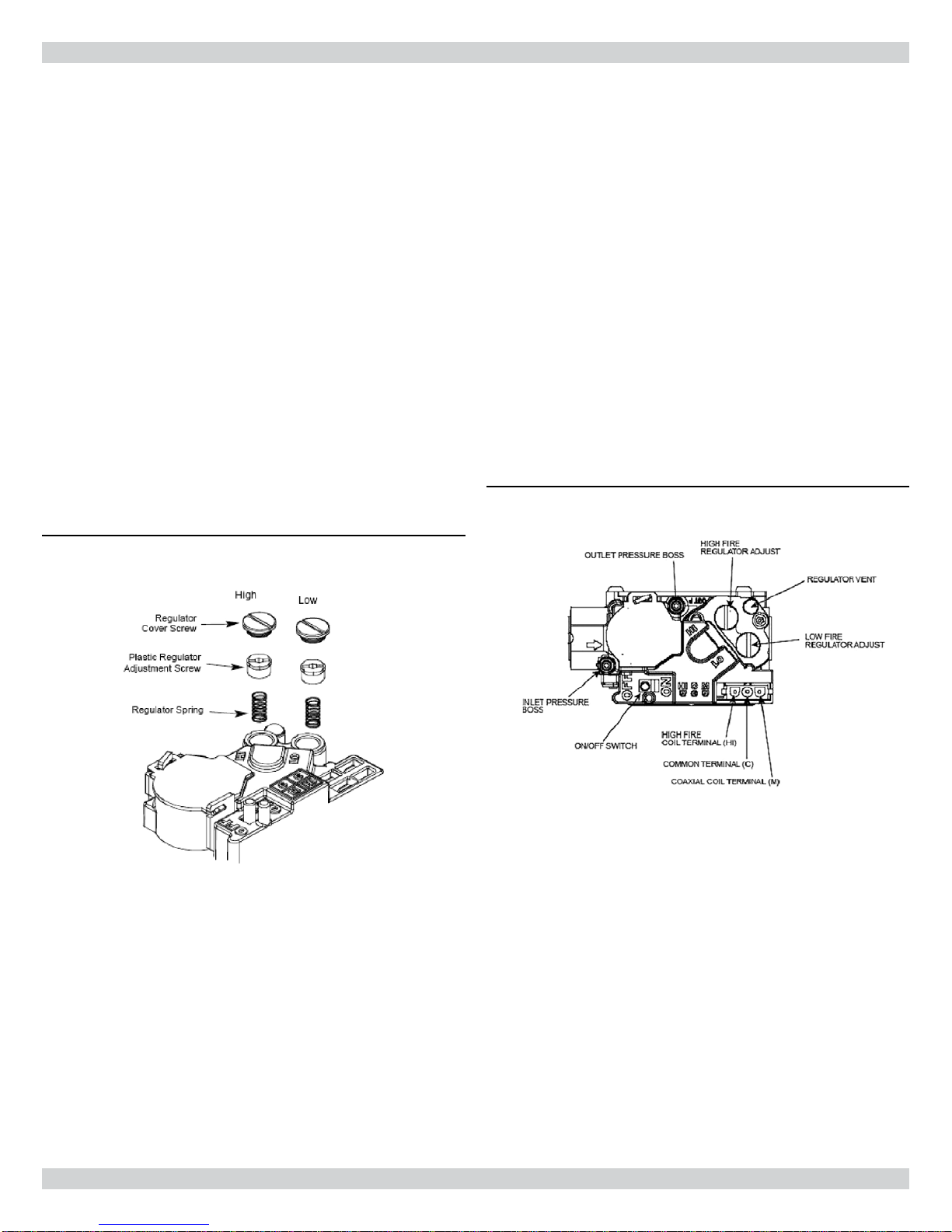
18 CONVERSIONS
Conversion Steps
To convert from sea level to high altitude, from
natural gas to LP gas, or from LP gas to natural gas, follow these
steps:
1.
Turn o gas supply to the furnace.
2.
Shut o electrical power to the furnace.
3.
Remove the front door to expose the gas train and burner assembly.
4.
Unfasten the ground joint union between the gas valve and gas
supply piping if applicable.
5.
Unplug the wires connected to the gas valve.
6.
Unfasten the burner manifold pipe from the burner assembly. It
is held in place by 2 screws on either end of the manifold pipe.
7.
Remove the existing ori ces with a
7/16” socket, box or open end wrench. Install the replacement ori ces. e ori ce spuds are brass, and do not normally
require pipe dope. A light grease may be used to lubricate
the threads. e ori ce spuds have tapered threads.
OVER-TIGHTEN!!
DO NOT
8.
Re-install the burner manifold pipe assembly following steps 4,
5, and 6 in reverse order.
9.
Remove both regulator cover screws. See
10.
Remove both regulator adjustment screws (beneath the cover
screws).
11.
Remove both Natural Gas regulator springs (color-coded silver/
plain) from regulator sleeves.
12.
Insert the L.P. regulator springs (provided in the conversion kit
and color-coded white) into the regulator sleeves.
13.
Replace the High regulator adjustment screw and adjust approximately 12 turns in, from fully out.
14.
Replace the Low regulator adjustment screw and adjust approximately 8 turns in, from fully out.
15.
Apply a liberal amount of pipe joint
compound or pipe thread tape to the threads and reassemble
the piping previously removed. Note: the pipe joint compound
must be resistant to L.P. gas.
Figure 30
.
Figure 31 - White Rodgers 36G54 Gas Valve
Figure 30 - White-Rodgers 36G54 Springs and Regulator
Screws
Checking The INLET Gas Pressure
White-Rodgers 36G54 Two Stage Gas Valve.
1.
Turn o the gas and electrical supply.
2.
Back inlet pressure test screw (inlet pressure boss, see F
31
) out one turn (counterclockwise, not more than one turn)
with a 3/32” Allen wrench.
3.
Attach a hose and calibrated U-tube manometer to the inlet
pressure boss. Hose should overlap boss 3/8”. e manometer
must have a scale range of at least 0” to 15” of water column.
4.
Turn ON the gas and electrical supply and operate the furnace
and all other gas consuming appliances on the same gas supply
line. Using a soap and water solution, check for leaks around
the gas valve/manifold connection and the burner ori ces.
Repair any leaks before continuing.
igure
37
Page 38
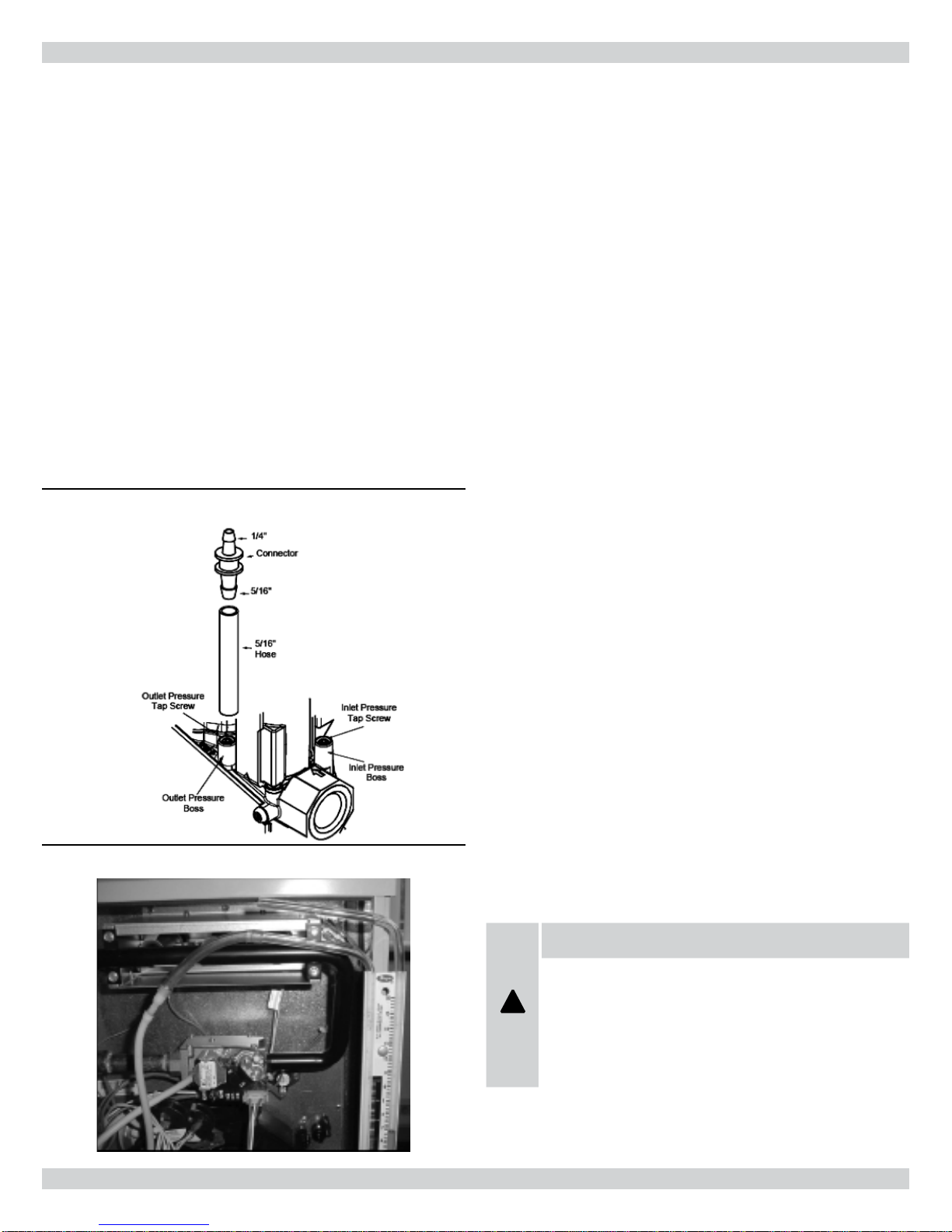
18 CONVERSIONS
5.
Measure furnace gas inlet pressure with burners ring. Inlet
pressure must be within the range speci ed on the furnace
rating plate. 5-7” w.c (Natural Gas) or 11-14” w.c. (LP). If the
inlet pressure di ers from the rating plate, make the necessary
adjustments to pressure regulator, gas piping size, etc. and/or
consult with local gas utility.
6.
Turn o gas and electrical supply to furnace, remove the manometer hose from the inlet pressure tap boss, and tighten the
inlet pressure tap screw using the 3/32” Allen wrench. (clockwise, 7 in-lb minimum).
7.
If working on a natural gas system, contact the gas utility. ey
may insist on any service regulator adjustments being made by
their own sta .
If problems were encountered with obtaining enough pressure on
the manifold, rst examine the gas piping system to ensure that it
is correctly sized. Pipe sizing is speci ed in CAN/CGA-B-149.1 &
2, and in NFPA 54 / ANSI Z223.1. Be sure to check for restrictions,
partially closed valves, etc.
Figure 32 - Valve Pressure Kit
Figure 33 - Manometer Measuring Gas Inlet Pressure
Setting The Manifold Gas Pressure
When the installation is completed to the “Start-up & Setup”
stage, test the gas manifold pressure by following these steps:
White-Rodgers 36G54 Two Stage Gas Valve.
1.
Turn o the gas and electrical supply before proceeding.
2.
Back outlet pressure test screw (outlet pressure boss, see g.31)
out one turn (counterclockwise, not more than one turn) with
a 3/32” Allen wrench. Attach a hose and calibrated U-tube
manometer to the outlet pressure boss. Hose should overlap
boss 3/8”. e manometer must have a scale range of at least 0”
to 15” of water column.
3.
Turn on the gas supply and electrical power
to the furnace and energize main solenoid by connecting R to
W1 on the integrated control board. Do not energize the HI
solenoid
4.
Remove regulator cover screw from the low outlet pressure
regulator adjust tower ( g.31) and turn the plastic regulator
adjustment screw clockwise to increase manifold pressure or
counterclockwise to reduce manifold pressure. Always adjust
regulator according to original equipment manufacturer’s
speci cations listed on the appliance rating plate. Replace regulator cover screw.
5.
Energize main solenoid as well as the HI terminal by connecting
R to W1 and W1/W2 on the integrated control board. Remove
regulator cover screw from the high outlet pressure regulator
adjust tower ( g.31) and turn the plastic regulator adjustment
screw clockwise to increase manifold pressure or counterclockwise to reduce manifold pressure. Manifold pressure should be
set to 1.5” w.c low re, 3.5” w.c high re for natural gas, 4.0” w.c
low re, 10.5” w.c high re for LP gas. Always adjust regulator
according to original equipment manufacturer’s speci cations
listed on the appliance rating plate. When the correct pressure
has been established, securely replace the regulator cover screw.
6.
Turn o the gas and electrical supply to the furnace.
38
WARNING
ALL REGULATOR ADJUSTMENTS MUST BE DONE
BY A TRAINED, QUALIFIED TECHNICIAN. IMPROP-
!
ER MODIFICATIONS OR ADJUSTMENTS CAN RESULT IN FIRE OR EXPLOSION CAUSING PROPERTY
DAMAGE, SEVERE PERSONAL INJURY OR LOSS OF
LIFE.
Page 39
18 CONVERSIONS
7.
Remove the manometer hose from the outlet pressure tap boss,
and tighten the outlet pressure tap screw using the 3/32” Allen
wrench. (clockwise, 7 in-lb minimum).
8.
Turn on the gas supply and electrical power to the furnace.
9.
Turn on system power and energize valve.
10.
Using a leak detection solution or soap suds, check for leaks at
pressure boss screw. Bubbles forming indicate a leak. SHUT
OFF GAS AND FIX ALL LEAKS IMMEDIATELY
19 ELECTRICAL SPECIFICATIONS
In some circumstances, high inlet pressure can be remedied with the
use of an in-line appliance regulator. If an in-line appliance regulator
is used, ensure that it has the capacity to adequately handle the gas
volume required by the furnace and any other appliances receiving
gas from the header serving the furnace.
Electrical Wiring & Connections
Before proceeding with the electrical connections, ensure that the
available electrical supply is compatible with the voltage, frequency
and phase listed on the appliance rating plate.
All furnaces are rated 120 vac, 60 Hz, 1 Ø. e amperage rating is 15
amps or less.
Each furnace requires a dedicated 20 amp over-current device, either
a 20 amp circuit breaker or a 20 amp Type D time delay fuse. It is
permissible to connect furnace accessories such as humidi er transformers, condensate pumps and electronic air cleaners. If adding accessory equipment to the furnace circuit, ensure that the combined
amperages listed on the appliance rating plates does not exceed the
rating of the over-current device.
In Canada, all electrical work must be in accordance with the latest
edition of CSA-C22.1, Canadian Electrical Code Part 1, and any applicable local code.
WARNING
SHUT OFF ELECTRICAL POWER AT THE FUSE BOX
OR SERVICE PANEL BEFORE MAKING ANY ELEC-
!
TRICAL CONNECTIONS. FAILURE TO DO SO CAN
CAUSE ELECTRICAL SHOCK RESULTING IN PERSONAL INJURY OR LOSS OF LIFE.
WARNING
• THE FURNACE CABINET MUST HAVE AN UNINTERRUPTED GROUND.
• A GROUND WIRE IS PROVIDED IN THE ELECTRI-
!
CAL JUNCTION BOX.
• DO NOT USE GAS PIPING AS A GROUND.
FAILING TO GROUND THE FURNACE PROPERLY
CAN RESULT IN ELECTRIC SHOCK RESULTING IN
PERSONAL INJURY OR DEATH.
39
Page 40
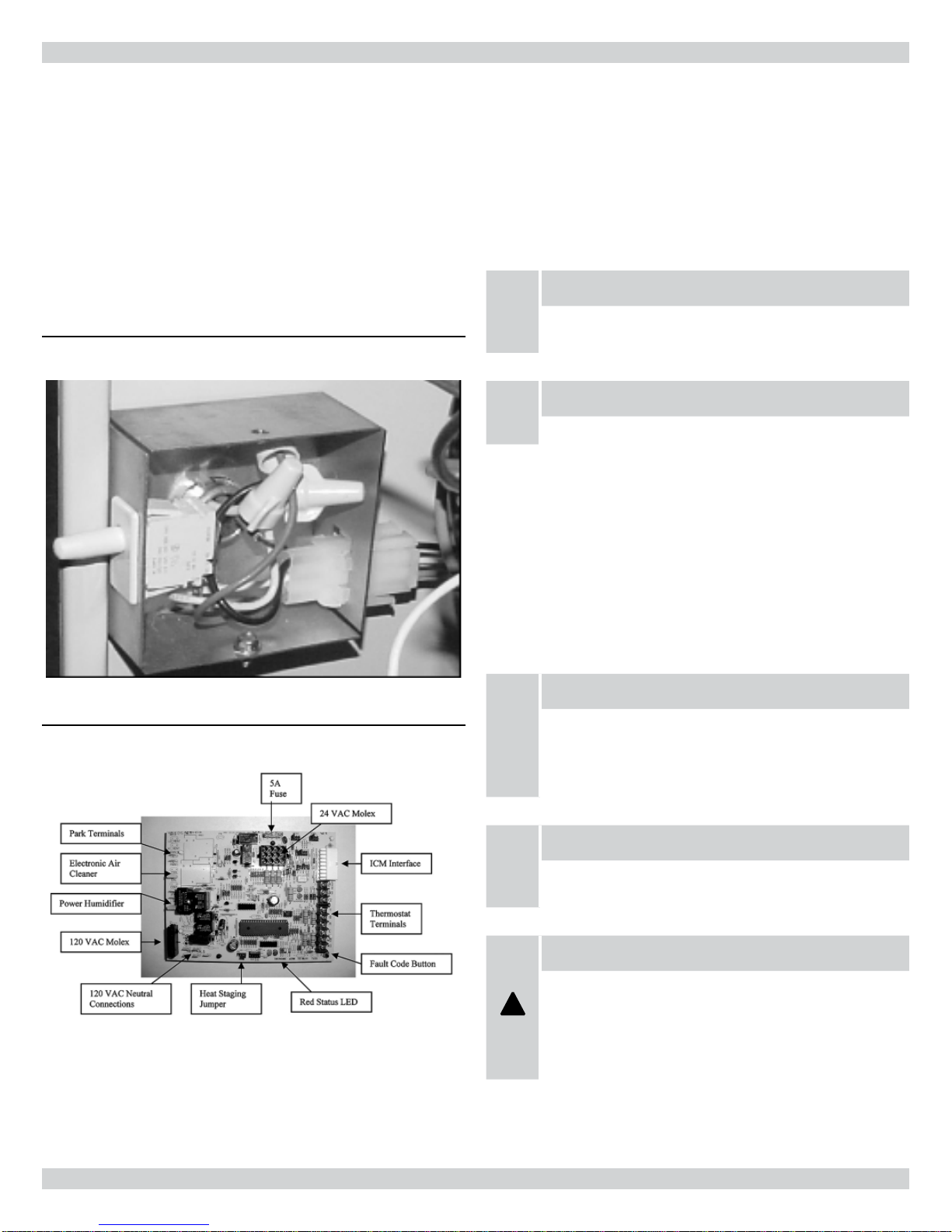
19 ELECTRICAL SPECIFICATIONS
In the United States, all electrical work must be in accordance with
the latest edition of the National Electrical Code, ANSI / NFPA 70.
Although a suitably located circuit breaker may serve as a service
switch, a separate service switch is recommended. A separate service
switch is necessary if the circuit breaker is in a location where accessing it would require getting close to the furnace, or if the furnace
is located between the main electrical panel and the entry to the
furnace room. e furnace switch (service switch) should be clearly
labeled, and installed in a location where it is not likely to be mistaken as being a light switch or
similar control.
Figure 34 - Electrical Connections/Molex Connector
120V Furnace Connection
e furnace is shipped fully wired except for the connections to the
house wiring. e furnace power connections are made in a junction box inside the blower compartment. e junction box is factory
installed on the le hand side; however, it may be moved to the right
hand side. e junction box contains a BLACK wire to be connected
with L1 (hot), a WHITE wire to be connected with L2, the Neutral,
and a GREEN wire to be connected to the ground.
NOTICE
NOTE: Use good quality wire nuts such as Marrette® connectors, Ideal® wire nuts, etc.
NOTICE
IMPORTANT: Use copper conductors only
If the junction box must be moved to the right hand side
of the unit:
Figure 35 - Integrated Hot Surface Ignition Control
1.
Unfasten the junction box from the le hand side.
2.
Remove the right side panel knock-out.
3.
Remove the junction box cover hook screw and re-install it on
the opposite side of the box.
4.
Fasten the junction box to the right hand panel.
NOTICE
L1 (hot) and L2 (neutral) polarity must be
observed when making eld connections to the
furnace. e ignition control may not sense ame if
L1 and L2 are reversed. e ground is also essential.
NOTICE
IMPORTANT: Electrical wiring and components must be
protected from moisture including water and condensate.
WARNING
THIS FURNACE IS EQUIPPED WITH A BLOWER
DOOR SAFETY SWITCH. DO NOT DISABLE THIS
!
SWITCH. FAILURE TO FOLLOW THIS WARNING
CAN RESULT IN ELECTRICAL SHOCK, PERSONAL
INJURY, OR LOSS OF LIFE.
40
Page 41
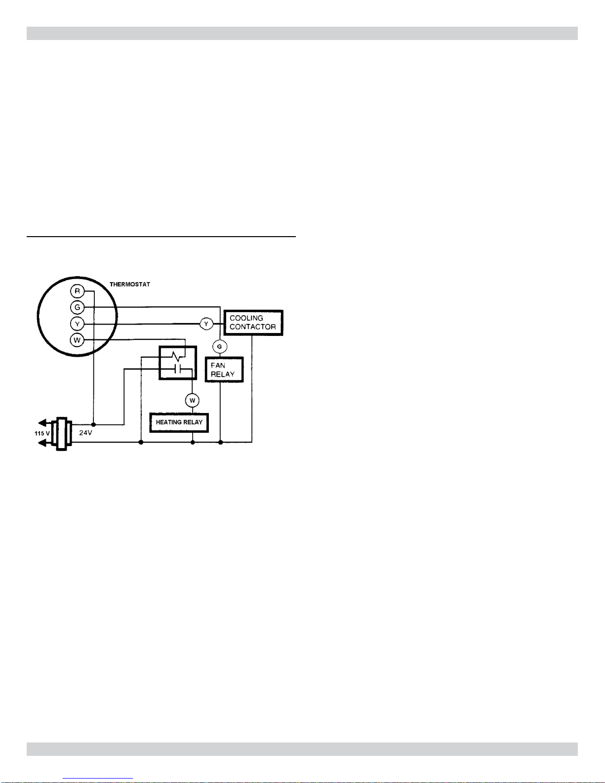
20 LOW VOLTAGE WIRING
e low voltage terminals are located in the control box mounted to
the blower assembly. e furnace is air conditioning ready. Insert the
thermostat and air conditioner contactor low voltage wiring through
a knockout provided in the side panel above the supply voltage
knockout using a eld supplied bushing. Route the control wiring to
the control panel to connect to the 24 volt terminal screws.
Thermostat
e room thermostat must be compatible with the integrated control
in the furnace. Electro-mechanical thermostats should be rated 30 V
/ 1.5 amps.
Figure 36- Isolation Relay
Single Stage Thermostat
e automatic heat staging option allows a single stage thermostat
to be used with a two stage furnace. e control provides a movable
jumper (P5) to select between 5 minute and *10 minute automatic
staging. Automatic staging time begins when the blower is energized
a er the heat blower delay period. If the jumper is in the 5 minute position, the control will automatically start high heat a er 5
minutes of continuous low heat operation. If the jumper is in the
*10 minute position, the control will automatically start high heat
a er 10 minutes of continuous low heat operation. Once high heat
is started from automatic staging, the demand for high heat remains
until the heat call is satis ed.
* Factory Setting
Two Stage Thermostat
When connecting a two stage thermostat, the jumper (P5) must be
in the “NONE” position. e control runs high heat from the thermostat W2 demand.
Most electronic or microprocessor based thermostats except those
with “current robbing” circuits should work satisfactorily. Consult
the instructions of the thermostat manufacturer for technical and
installation details.
Most compatibility problems can be overcome by
the use of an isolation relay. e isolation relay should be SPST with
a 24 volt coil. e switch ratings should be a minimum of 0.5 amps.
Figure 36
(
e thermostat and control wiring should be a minimum of 18 AWG
copper. Excessive lengths of wire may result in enough voltage drop
to impair the proper functioning of the furnace. For thermostat
wires in excess of 25 feet, use 16 AWG; 50 feet, use 14 AWG.
)
Thermostat Location
e thermostat should be located approximately 5 feet above the oor,
on an inside wall where there is good natural air circulation, and where
the thermostat will be exposed to average room temperatures. Avoid
locations where the thermostat will be exposed to cold dra s, heat from
nearby lamps or appliances, exposure to sunlight, heat from inside wall
stacks, etc.
Thermostat Heat Anticipator Setting: 0.1 AMP (Honeywell)
41
Page 42
21 OPTIONAL ACCESSORIES FIELD SUPPLIED/INSTALLED
Electronic Air Cleaner
e integrated furnace control has provisions to supply power and
control an electronic air cleaner rated at 120vac, 1.0 amp max. 120
volt power will be available at these terminals whenever the
circulating fan is operating in the heating or cooling modes.
22 STARTUP PROCEDURES
is furnace is equipped with a HSI (Hot Surface Ignition) device.
Each time that the room thermostat calls for heat, the HSI lights the
main burners directly. See the lighting instructions on the furnace.
To Start The Furnace
1.
Remove the burner compartment access door.
2.
Shut o the electrical power to the furnace and set the room
thermostat to its lowest setting.
Power Humidi er
e integrated furnace control has provisions to supply power and
control a line voltage humidi er or the primary of a 120 / 24 volt
humidi er step down transformer, rated at 120vac, 1.0 amp max.
NOTICE
All HUM and EAC terminals are 120V. Do not directly
connect 24V equipment to these terminals.
WARNING
SHOULD OVERHEATING OCCUR OR THE GAS
BURNERS FAIL TO SHUT OFF, CLOSE THE MANUAL
GAS VALVE FOR THE FURNACE BEFORE SHUTTING
OFF THE ELECTRICAL POWER TO THE FURNACE.
!
FAILURE TO DO SO CAN CAUSE AN EXPLOSION OR
FIRE RESULTING IN PROPERTY DAMAGE, PERSONAL INJURY OR LOSS OF LIFE.
NOTICE
IMPORTANT: Ensure that the manual gas control switch
has been in the “OFF” position for at least 5 minutes. Do
not attempt to manually light the main burners.
3.
Turn the gas control switch to the “ON” position.
4.
Replace the burner compartment access door.
5.
Restore electrical power to the furnace.
6.
Set the room thermostat to a point above room temperature to
light the furnace.
7.
A er the burners are lit, set the room thermostat to the desired
temperature.
To Shut Down The Furnace
1.
Set the room thermostat to its lowest setting.
2.
Remove the burner compartment access door.
3.
Turn the gas control switch to the “OFF” position.
4.
e furnace appliance shut-o valve may be closed if desired.
5.
Power to the furnace must remain on for the air conditioner to
work.
BEFORE RESTARTING THE FURNACE, CHECK ALL
PLASTIC VENTS AND WIRES FOR DAMAGE.
NOTICE
NOTE: On initial startup, the drain trap assembly will be
dry. A dry trap will allow ue gases to ow through the
recovery coil drain, which will prevent the condensate
from draining from the recovery coil. If enough condensate accumulates in the recovery coil, the recovery coil
pressure switch will sense this condition and break its
electrical contacts, and extinguish combustion. If this takes
place, the induced blower will stop a er a brief post-purge
cycle, the condensate will drain out and ll the trap. If the
thermostat is still calling for heat, the ignition sequence
will start again a er a 5 minute wait.
42
Page 43

22 STARTUP PROCEDURES
Sequence Of Operation
1.
Room temperature drops causing the room thermostat to call
for rst stage heat by connecting “W1” to “R”. e control veri es the limit switch is closed and both low and high pressure
switches are open. e control energizes the induced dra motor on high speed and waits for the low pressure switch to close.
e inducer remains on high speed and begins a 15 second prepurge period. e high pressure switch is ignored. If the low
pressure switch does not close within 60 seconds, the control
will ash “2” on the red Status LED, and de-energize the
inducer for 60 minutes.
2.
When the 15 second pre-purge time has elapsed, the control energizes the HSI output for a 5 second warm-up period (10 seconds on retries). e control energizes the low main gas valve.
4 seconds a er the gas is energized, the control de-energizes the
HSI output and leaves the gas energized another 1 second for
ame proving. If ame is present at the end of trial for ignition
time, the control leaves the gas valve energized, inducer on high
speed, and begins heat blower on delay. e control always
ignites on high inducer/low gas and ignores second stage call
for heat until low heat is established for
15 seconds.
3.
Blower on delay time begins when the gas valve is energized.
e control provides the ECM (Electronically Commutated
Motor) low heat speed signal when ame is proven, and starts
a 30 second so start (slowly ramp up) blower delay before full
capacity blower level.
4.
When there is a demand for 2nd stage heat from thermostat W2
or automatic staging, the control changes the inducer from low
to high speed. When high pressure switch closes, the control
changes indoor blower speed from Low heat to High heat and
energizes high gas output. If the High pressure switch is open
the Green LED will ash. If the High pressure switch is closed
the Green LED will be on. High gas valve drops out while High
pressure switch is open because it is directly in series with the
High pressure switch.
5.
When the thermostat W2 call ends and W1 remains (two stage
thermostat), the control de-energizes the high gas output and
immediately changes inducer speed from high to low. With the
thermostat heating contacts open (single stage thermostat), the
ames extinguish immediately and the inducer blower stops
a er a 5 second post purge time.
6.
Blower o delay is handled by the ECM
(Electronically Commutated Motor). e control de-energizes
the ECM heat signal when the gas valve de-energizes, and starts
a programmed so stop (slowly ramp down) delay period.
In The Event Of Flame Failure:
If ame is lost, the control de-energizes the gas valve within 2 seconds, switches the induced dra motor to high speed (if not already
on high), and begins timing the inter-purge delay. e indoor blower
motor will be energized and/or remain energized on heat speed for
the programmed delay o time. When the inter-purge delay is over,
the control will re-cycle up to 5 ame losses (4 re-cycles) within a
single call for heat before going into lockout. e control ashes “8”
on the red LED if lockout is due to too many ame losses.
Checking Furnace Input
e natural gas supply pressure should be a maximum of 7” w.c. and
minimum of 5” w.c. e burner manifold pressure is factory set to
3.5” w.c. High Fire, 1.5” w.c. Low Fire. e input rating of the furnace is based on 1000 BTU/cu. . gas with a speci c gravity of 0.6.
Since heating values for the gas vary geographically, the actual furnace input and output will vary accordingly. For example, natural gas
with a 1000 BTU/cu. . heating value will reduce the input to 93%
of the rated input. Natural gas with a 1100 BTU/cu. . heating value
will increase the input to approximately 103% of the rated input. is
is not usually a problem; however, adjustments to compensate for
this can be made by minor adjustments to the burner manifold pressure or by changing the burner ori ce size.
Any adjustments to the burner manifold pressure should be carried
out with the use of a manometer or calibrated magnehelic gauge. Do
not adjust the gas valve pressure regulator more than ±0.3” w.c.
NOTICE
IMPORTANT: Never adjust the input of the furnace to
exceed the input shown on the rating plate.
which should be followed to ensure proper installation and
operation.
In the previous example where the heating value of the gas is 1100
BTU/cu. ., the burner manifold pressure can be reduced 3% to 3.4”
w.c., which is within the ±0.3” w.c. speci cation to bring the input
into compliance. Refer also to “Setting the Gas Manifold Pressure”
and “High Altitude in the Gas Supply & Piping” section of this manual. Contact the fuel supplier for speci c gas heating content values.
Input =
where:
• input is expressed in BTU/Hr
• heating value of the gas is expressed in BTU/ft
• and time is the number of seconds required for
the test dial to indicate 1 cubic foot.
If using a gas meter with SI (metric) units:
Heating Value of Gas x 3600
Time in Sec. for 1 cu. ft.
3
• 1 cubic foot = 0.0283 cubic meters
• 1 cubic meter = 35.315 cubic feet
• 0.01 cubic meter = 0.3531 cubic feet
• 0.5 cubic meter = 1.766 cubic feet
43
Page 44
23 AIR FLOW
For proper furnace operation, air ow over the heat exchanger is of
utmost importance. Insu cient air ow accelerates metal fatigue and
failure in the heat exchanger and excessive air ow promotes accelerated corrosion of the heat exchanger.
NOTICE
IMPORTANT: Do not bypass this step of the start up
procedures.
TABLE 1A - RANGE OF TEMPERATURE RISE
Furnace Model Temperature Rise
60, 80, 100, 120
TABLE 1B - AIR FLOW FOR TEMPERATURE RISE
Furnace
Model
60 1501 1167 955 808
80 2001 1557 1274 1078
100 2502 1946 1592 1347
120 3002 2335 1910 1616
Furnace
Model
60 901 700 573 485
80 1201 934 764 647
100 1501 1167 955 808
120 1801 1401 1146 970
High Fire (HF) CFM Required for a ▲T of:
35 45 55 65
Low Fire (LF) CFM Required for a ▲T of:
25 35 45 55
High Fire (HF) 35 - 65°F
Low Fire (LF) 25 - 55°F
Temperature Rise Check
When the duct system is complete and the air lter or lters are in
place, determine if the air ow is correct for both low and high re
input rates..
1.
Insert a duct thermometer in the supply air duct. e thermometer should be placed as close as practical to the furnace, but out
of the “line of sight” of the heat exchanger (this prevents false
readings owing to radiant heat). Ensure that the thermometer
location is within the duct air stream. Avoid locations such as
the inside radius of an elbow, etc.
TABLE 10 - AIR FLOW
MODEL 95V ESP 0.1” to 1.0” w.c.
Input
60000 3 Ton NORM
80000 3 Ton NORM
80000 4 Ton NORM
100000 5 Ton NORM
120000 5 Ton NORM
Note: Moving the ADJUST jumper from the NORM position to the
(+) or (-) position will increase or lower the CFM by 15%
2.
Insert a duct thermometer in the return air duct as close to the
A/C
Tonnage
ADJUST
Jumper
COOL
Jumper
A 1200
B 1000
C 800
D 600
A 1200
B 1000
C 800
D 600
A 1600
B 1200
C 1000
D 800
A 2000
B 1600
C 1200
D 800
A 2000
B 1600
C 1200
D 800
CFM
furnace as practical. Ensure that the thermometer location will
be una ected by humidi er bypass ducts, etc. Choose a location
well within the main air stream.
3.
Operate the furnace long enough to obtain steady state conditions at both input rates (High Fire and Low Fire).
4.
When the two thermometers have stabilized, usually within
5-8 minutes, compare the two readings. Subtract the return air
temperature from the supply air temperature. e di erence is
the temperature rise, also called ∆T.
5.
Compare the measured ∆T to the temperature rise range shown
on the rating plate. Unless stated di erently on the rating plate,
the temperature rise should normally range between 35° to 65°F
High Fire, 25° to 55°F Low Fire. When adjusting the temperature rise, the ideal temperature is approximately mid-range.
If the measured ∆T is above the approved temperature range,
there is too little air ow. It must be increased by selecting the
appropriate “HEAT” jumper setting , removing restrictions
in the ductwork, or adding supply or return
ductwork.
If the measured ∆T is too low, there is too
much air fl ow.
44
Page 45

23 AIR FLOW
Calculating Air Flow
ere are circumstances where it may be desirable to know the air
ow delivery through the duct
system, such as when estimating the amount of air ow available for
air conditioning. is can be done by direct measurement with electronic or sloped manometers and velometers, or by counting the
number of times the amber CFM LED on the control board ashes.
Each ash signi es 100 CFM; count the ashes and multiply by 100
to determine the actual CFM delivered (for example: 10 ashes x 100
= 1000 CFM). Or use the formula in the next column.
CFM =
where:
Output
1.085 x
∆T
TABLE 11A - HEATING SPEEDS
ALL MODELS ESP 0.1” to 1.0” w.c.
HEAT
Jumper
A NORM 40 °F 50 °F
B NORM 35 °F 45 °F
C NORM 45 °F 55 °F
D NORM 50 °F 60 °F
Note: Moving the ADJUST jumper from the NORM position to the
(+) or (-) position will increase or lower the temperature rise by 15%
TABLE 11B - HEATING CFM
95V060-3 ESP 0.1” to 1.0” w.c.
HEAT
Jumper
ADJUST
Jumper
ADJUST
Jumper
Low-Fire ▲T
Range 25-55 °F
Low-Fire
CFM
High-Fire ▲T
Range 35-65 °F
High-Fire
CFM
• CFM is airfl ow in cubic feet per minute;
• ∆T is the temperature rise; and
• Output is the furnace output capacity from
the rating plate
NOTE: Output will vary directly with the input. If the
actual input is below the stated input, the output will
be reduced in the same ratio (93%).
.
Adjusting Blower Speeds
WARNING
DISCONNECT THE ELECTRICAL SUPPLY TO THE
FURNACE BEFORE ATTEMPTING TO CHANGE THE
!
BLOWER SPEED. FAILURE TO DO SO COULD RESULT
IN ELECTRICAL SHOCK RESULTING IN PERSONAL
INJURY OR LOSS OF LIFE.
is unit is factory set to run at the middle of the heating temperature rise range as listed on the rating plate. e cooling speed is set
to the maximum air ow designated in the model number.
ree sets of 4 position movable jumpers are provided for Heat,
Cool, and Adjust taps for a variable speed motor. ese tap jumpers
apply signals to the ECM motor without other interaction with the
control board.
A NORM 700 1050
B NORM 850 1105
C NORM 575 880
D NORM 525 819
TABLE 11C- HEATING CFM
95V080-4 ESP 0.1” to 1.0” w.c.
HEAT
Jumper
A NORM 1000 1350
B NORM 1150 1495
C NORM 900 1206
D NORM 800 1104
TABLE 11D HEATING CFM
95V120-5 ESP 0.1” to 1.0” w.c.
HEAT
Jumper
A NORM 1650 2200*
B NORM 1900 2200*
ADJUST
Jumper
ADJUST
Jumper
Low-Fire
CFM
Low-Fire
CFM
High-Fire
CFM
High-Fire
CFM
C NORM 1500 2070
D NORM 1325 1815
* Motor CFM maxium
45
Page 46
23 AIR FLOW
TABLE 11E HEATING CFM
95V080-3 ESP 0.1” to 1.0” w.c.
HEAT
Jumper
A NORM 1050 1376
B NORM 1250 1400*
C NORM 900 1242
D NORM 780 1108
* Motor CFM maximum\
TABLE 11E HEATING CFM
95V100-5 ESP 0.1” to 1.0” w.c.
HEAT
Jumper
A NORM 1200 1620
B NORM 1400 1820
C NORM 1100 1474
D NORM 950 1349
Note: Moving the ADJUST jumper from the NORM position to the
(+) or (-) position will increase or lower the temperature rise
by 15%
ADJUST
Jumper
ADJUST
Jumper
Low-Fire
CFM
Low-Fire
CFM
High-Fire
CFM
High-Fire
CFM
If the blower speeds require adjustment, follow these steps:
1.
Remove the blower compartment door.
2.
Locate the 4 position movable HEAT jumper to adjust heat
speed.
3.
Remove the jumper from position A
and place it on the corresponding letter B, C,
or D as required. Refer to
TABLE 11A-11E HEATING-
SPEEDS.
Dehumidi cation:
For situations where humidity control is a problem, a dehumidi cation feature has been built into the variable speed motor. At the start
of each cooling cycle, the variable speed motor will run at 82% of
the rated air ow for 7.5 minutes. A er 7.5 minutes has elapsed, the
motor will increase to 100% of the rated air ow. If this feature is not
desired, clip the jumper wire between Y and O on the integrated
furnace control board. With Y and O not jumpered, the variable
speed will reach 100% of the rated air ow within 10 seconds of a call
for cooling.
Additional dehumidi cation can be achieved by connecting a humidistat to the DEHUM and R terminals on the integrated furnace
control board. In this setup, the variable speed motor will operate at
a 10% reduction in the normal cooling air ow rate when there is a
call for dehumidi cation.
Both dehumidi cation methods described above can be utilized on
the same furnace.
Setting Blower “On” And “O ” Timings
Blower on/o delays are handled by ECM
motor programming. e control de-energizes the ECM heat signal
when the gas valve de-energizes. Features of this ECM variable speed
motor are that it will deliver a constant air ow within a wide range
of external static pressures, and also includes:
Soft Start:
up to the required operating speed. This feature in the heating
cycle allows the heat exchanger to reach operating temperature before the set heat speed, which minimizes noise and
increases comfort.
Soft Stop:
cycle, the ECM variable speed motor will slowly ramp down.
This feature allows for increased
energy effi ciency, and reduced noise levels.
This ECM variable speed motor will slowly ramp
At the end of the heating or cooling
NOTICE
NOTE: Temperature rise should always be re-checked
whenever blower speed is changed.
4.
To adjust the cooling air ow, remove the COOL jumper from
position A and place it on the corrosponding letter B, C, or D.
Refer to
TABLE 10 AIR FLOW
.
Moving the ADJUST jumper from the NORM to the (+) or (-) position will cause the air ow to be increased or lowered by 15%.
e TEST position on the ADJUST tap is not used.
Continuous Fan Operation
When the thermostat continuous fan (G) switch is on without a call
for heat or cooling, the indoor fan is immediately energized up to
50% of the cooling speed. e fan remains energized as long as the
call for fan remains without a call for heat or cooling. is feature
allows continuous circulation of air between calls for heating or
cooling.
If a call for heat (W) occurs during continuous fan, the blower will
de-energize.
46
Page 47
23 AIR FLOW
If a call for cool (Y) occurs simultaneously with the call for fan (G),
the call for cool overrides the call for fan and the blower remains o
for the cooling on delay period.
24 MAINTENANCE AND TROUBLESHOOTING
WARNING
DISCONNECT THE ELECTRICAL POWER SUPPLY TO
THE FURNACE BEFORE ATTEMPTING ANY MAIN-
!
TENANCE. FAILURE TO DO SO CAN CAUSE ELECTRICAL SHOCK RESULTING IN PERSONAL INJURY
OR LOSS OF LIFE.
CAUTION
Label all wires prior to disconnection when servicing
!
controls. Wiring errors can cause improper and dangerous
operation.
Always verify proper operation a er servicing.
TABLE 12 - CONTINUOUS FAN CFM
MODEL
95V060-3 1/2 A NORM 600
95V080-3 1/2 A NORM 600
95V080-4 3/4 A NORM 825
95V100-5 1 A NORM 865
95V120-5 1 A NORM 930
Note: Moving the ADJUST jumper from the NORM position to the (+)
or (-) position will increase or lower the continuous fan CFM by 15%
Recommended:
Motor
HP
Electronic air lters using electrostatic precipita-
COOL
Jumper
ADJUST
Jumper
Continuous
Fan (CFM)
tion to remove dust are an excellent ltration device. A 16” x 25”
model is an ideal t with this furnace in the case of a side mounted
return air inlet. e furnace control module is supplied with electrical terminals for use with electronic air cleaners.
A 16” x 25” x 1” lter kit part number 550001458 can be ordered for
use on this appliance. is kit includes the lter rack and washable
lter.
NOTICE
NOTE: If two return air inlets are used, both must be
equipped with lters.
Air Filter
e lter should be inspected frequently and cleaned as necessary.
We recommend a monthly inspection at rst, perhaps coinciding
with the arrival of the monthly fuel bill as a reminder. e frequency
may be increased or decreased depending on experience and conditions.
Avoid the use of the berglass throw-away lters. ey tend to block
up quickly, which may result in higher than normal operating temperatures, and lower e ciency.
Some paper media high e ciency lters, sometimes identi ed as
HEPA lters can do an e ective and excellent ltration of the air;
however, some models may also cause a large pressure drop across
the lter. e contractor should assess the capabilities of the duct
system to deliver su cient air ow if this type of lter is considered.
47
CAUTION
Do not operate the furnace for prolonged
periods of time without an air fi lter.
A portion of the dust entrained in the air
!
may lodge in the supply air ductwork and
registers. Any recirculated dust particles
will be heated and charred by contact with
the furnace heat exchanger. This residue
will soil ceilings, walls, drapery, carpets,
and other household articles.
Page 48
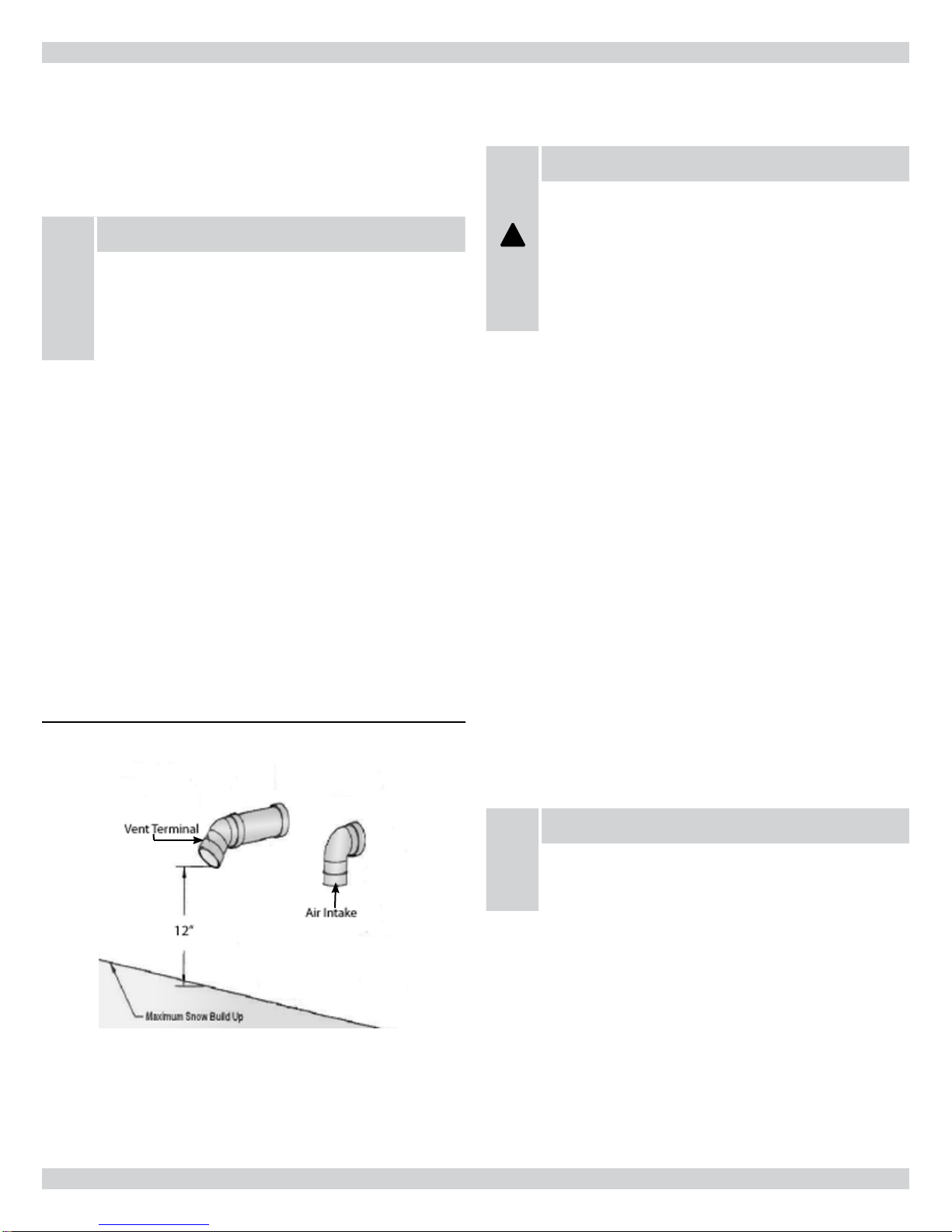
24 MAINTENANCE AND TROUBLESHOOTING
Lubrication
Both the induced dra blower motor and circulating fan motor are
ball-bearing type motors. Neither requires routine lubrication.
NOTICE
IMPORTANT: e motor bearings were pre-lubricated
by the motor manufacturer. Do not attempt to lubricate
them. Excess lubrication will void the warranty, shorten
the service life if the motors, and will attract the buildup of
dust and dirt.
e induced blower motor and circulating fan motor must be
cleaned on a periodic basis by a quali ed service technician. Dust
buildup in the ventilation ports of the motor will cause the motor to
not dissipate heat properly resulting in reduced service life.
Terminations
e combustion air and exhaust terminals should be inspected occasionally to ensure that they are free of obstructions and debris.
If screens were used in either terminal, ensure that they are free of
debris, corrosion, or anything preventing the free ow of air. In
weather conditions when snow build-up occurs, the homeowner
should inspect the vent terminal and air intake regularly to ensure
they are free and clear of snow. Maintain at least one foot of clearance between snow build-up and vent/combustion air intake openings at all times. Clear away excess snow to maintain this clearance.
Figure 37 - Vent Terminal Clearance
WARNING
HOLES IN THE EXHAUST PIPING OR FURNACE
HEAT EXCHANGER CAN ALLOW TOXIC FUMES TO
ENTER THE HOME AND CIRCULATE THROUGH
!
THE DUCT SYSTEM RESULTING IN CARBON MONOXIDE POISONING OR DEATH. IF LEAKS ARE
FOUND IN THE FURNACE HEAT EXCHANGER, IT
MUST BE REPLACED.
Operating Tips
1.
Clean air lters maximize e ciency and reduce heating costs.
2.
During the heating season, keep windows and doors closed to
reduce the heating load on the system.
3.
Avoid excessive use of kitchen exhaust hoods and other exhaust
fans to reduce the heating load on the system.
4.
Arrange the furniture and drapes so that the supply air registers
and return air grilles are unobstructed.
5.
If you have a perimeter duct system, ideally, the warm air
should bathe the cold exterior walls. Avoid the use of plastic
de ectors on the supply air registers which tend to short circuit
the warm air straight into the return air grilles. ese de ectors
are o en the cause of cool draughts across the oor.
6.
Avoid placing heat producing appliances such as televisions,
radios, lamps, etc. in a location to in uence the thermostat.
7.
Keep combustible articles at least 3 feet away from the furnace.
Do not block access for servicing the furnace Do not use the
combustion air or exhaust piping as a hanger for clothes or
anything else.
Intake Air/Exhaust Piping
e combustion air intake piping and exhaust piping should be
inspected periodically for sags, evidence of leakage etc. If either
condition exists, contact your installation contractor, service agency
or fuel supplier.
NOTICE
IMPORTANT: Never attempt to operate the furnace without the blower door and combustion compartment door in
place or when the blower has failed.
Annual Inspection/Service
e furnace must be inspected annually by a quali ed installation
contractor, service agency or fuel supplier. Your annual inspection
will normally cover the following:
HEAT EXCHANGER
corrosion. e ue passages (heat exchanger tubes) should be free of
scale or excessive corrosion. e top row of heat exchanger tubing
is accessible for cleaning with a small diameter wire-handled brush
- e heat exchanger should be inspected for
48
Page 49

24 MAINTENANCE AND TROUBLESHOOTING
by removing the burner assembly. e bottom row is only accessible if the heat exchanger is removed and the rear ue box cover
is removed. e recovery coil (secondary heat exchanger) may be
cleaned by accessing the rear ue box cover or removing the front
manifold cover. A er clearing accumulated scale, observe the burner
ames. If there appears to be ame distortion, check the combustion air
intake and exhaust piping and terminals for blockage. Also check for
signs of soot in the condensate drainage. If ame distortion continues
a er eliminating the blockage in the piping as the cause, it may be
necessary to replace the tubular heat exchanger.
NOTICE
NOTE: Prior to removal of rear ue box cover or front
manifold cover, ensure that replacement gaskets are available to ensure proper sealing of the heat exchanger when
re-assembled.
BURNERS -
are free of deterioration, dust and debris, and properly aligned with
the heat exchanger. In most cases, a simple vacuuming with a brush
attachment will adequately clean the burner assembly and burner
compartment.
!
e ame sensor should be inspected and cleaned with ne steel
wool or Scotch-Brite™ scrubbing pad. e wiring connection should
be checked to ensure that it is tight and corrosion free.
e burners should be inspected to ensure that they
CAUTION
Be careful when working on the burner assembly. e hot
surface igniter is fragile and can break easily.
NOTICE
NOTE: is is a critical connection. Small amounts of
corrosion can signi cantly increase the internal resistance
of the connection. A relatively small increase in resistance
can result in a large decrease in ame signal.
DRAINAGE
and cleaned if necessary. If the drain trap assembly, or any other
component becomes blocked, condensate may backup into the
secondary or primary heat exchanger causing nuisance trip-outs
of the pressure switches or limit switch. e condensate should be
observed for signs of dirt, carbon, debris, etc.
If a condensate neutralizer has been added to the condensate drain,
it should be inspected, cleaned, or the condensate neutralizing media
should be replaced to ensure clear condensate ow.
INDUCED BLOWER
inspected and cleaned if necessary. Clear any dust buildup from the
ventilation ports.
CIRCULATING FAN
be checked to ensure that it is free of excessive dust buildup, debris,
etc. e mechanical fasteners should be inspected and checked for
proper tightness and parts alignment. e motor ventilation ports
should be cleaned if necessary to prevent restriction to cooling by air
over the motor.
ELECTRICAL
ensure that they are tight and corrosion free. Repair any connections
that have become loose or corroded.
FURNACE OPERATION
annual inspection and servicing to:
1.
Test all safety related controls.
2.
Determine that the temperature rise falls within the range
shown on the appliance rating plate.
3.
Ensure that the burner ignition is smooth and that the ames
are smooth so blue, and not impinging on the heat exchanger.
- e condensate drainage system should be inspected
- e induced blower motor should be
- e condition of the circulating fan should
- All electrical connections should be examined to
- e furnace should be cycled during the
49
Page 50
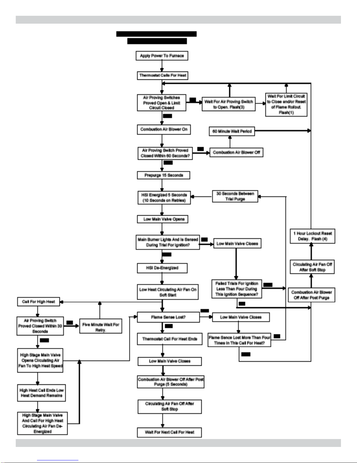
25 TROUBLESHOOTING FLOWCHART
50
Page 51
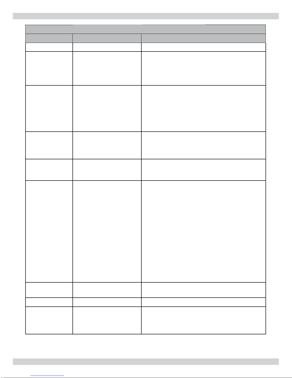
26 DIAGNOSTIC CODES FOR STATUS LED
A RED LED is provided to indicate furnace operating status
LED Condition Fault Condition Check
LED ON Normal operation No action required. Control OK.
Line voltage input power at L1 and Neutral
No power to control or
LED OFF
control
hardware fault detected
1 Flash High limit switch open
2 Flashes
Pressure switches open
with inducer on
connectors control board.
System wire harness in good condition and
securely connected at both ends.
Open limit switch.
Limit switch and wiring in good condition and
securely connected.
Check for blocked air fi lter, correct temperature rise,
blower speed selection, closed ducts, ect.
Pressure switches operation, tubing and wiring.
Obstruction or restrictions in venting preventing
proper air fl ow.
3 Flashes
Pressure switches closed
with inducer off
4 Flashes Control in 1 hour lockout
5 Flashes L1/Neutral Polarity problem
Pressure switches stuck closed.
Pressure switches mis-wired or jumpered.
Gas supply OFF, or gas supply pressure too low to
operate furnace.
Damaged or broken HSI element.
Line voltage input power at L1 and Neutral
connectors control board.
Furnace not properly earth grounded.
Flame sensor rod contaminated or in incorrect
position.
HSI element located in wrong position.
Hot surface element or fl ame sensor wiring in good
condition and properly connected.
Check supply voltage to ensure proper polarity to
L1 and Neutral connections.
6 Flashes Not Used
7 Flashes
Pressure switch cycle
lockout
Pressure switches operation, tubing and wiring.
Obstruction or restrictions in venting preventing
proper air fl ow.
51
Page 52
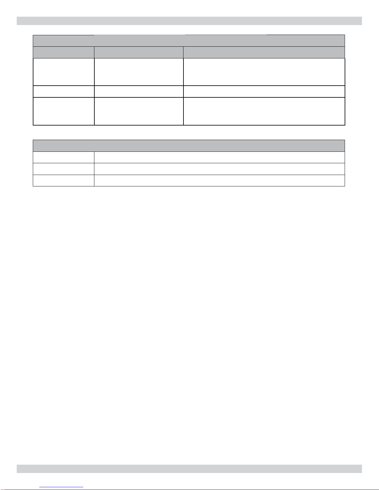
26 DIAGNOSTIC CODES FOR STATUS LED
A RED LED is provided to indicate furnace operating status
LED Condition Fault Condition Check
8 Flashes
9 Flashes Not used
10 Flashes Flame present with gas off
A GREEN LED is provided to indicate high heat state
LED off No demand for high heat
LED on High heat demand, operating normally
LED fl ashing High heat demand, high pressure switch not closed
Fault Code History
Lockout due to too many
fl ame dropouts
Check system for proper ground.
Dirty, oxidized or failed fl ame sensor.
Flame at main burner.
Gas valve.
The control stores the last 5 fault codes in memory.
When the push-button switch is pressed for less than
5 seconds, the control will fl ash the stored fault codes
when the switch is released. The most recent fault code
is fl ashed fi rst, the oldest last.
Fault history may be cleared by holding the push-button
switch for more than 5 seconds.
52
Page 53
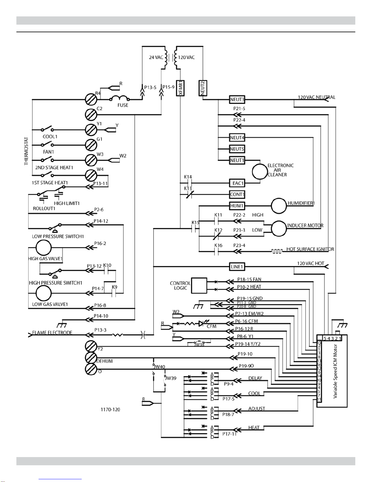
27 WIRE DIAGRAM FOR TWO STAGE FURNACE WITH ECM
Figure 38 - Wire Diagram For Two Stage Furnace With ECM
53
Page 54
28 VENTING CHECKLIST
✓
VENTING CHECKLIST
Vent pipe must be sloped to drain from outlet back to furnace.
Exposed vents and drains must be heat traced.
Vents exiting house must be well sealed to prevent exhausts from re-entering the house.
Vents and intake must be 12” above grade. For Massachusetts see page 7.
In Canada all venting material must be identi ed as ULC S636 and be readily accessible for
visual inspection for the rst 3 . (900mm)
Use large radius elbows where possible.
Exhaust vents must not be near windows or other fresh air intakes.
Support vents rmly. Keep out of work areas to prevent damage.
Clamp and gasket all vent exits to furnace panels to insure airtight seal.
Equivalent vent length must be less than the allowable length in Table 6 Direct and NonDirect Vent Lengths.
If there is a choice, the exhaust should be shorter than the intake vent.
For indirect vent, installer must calculate size of room to determine if outside air is required.
Use direct vent for commercial installations that use chemicals (Hair Salons, etc.)
Avoid exposure to windy side of house.
Heat Exchanger (suction) drain must be trapped separate from vent drain (pressure). A/C
drain must not be inserted before heat exchanger and vent drain trap.
Exhaust vent and combustion air intake must be located within the same wind pressure
zone when installed in a direct vent application using outdoor combustion air.
54
Page 55
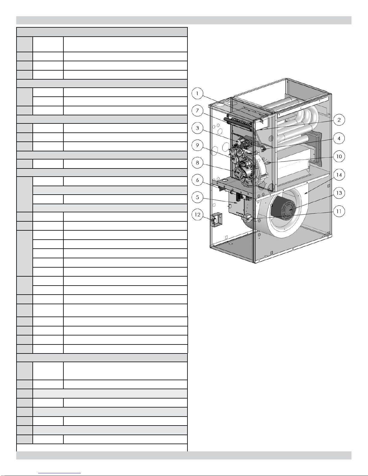
Item Kit Number
1 550001515
2 550001528
3 550001656
WHITE RODGERS 36G54 TWO STAGE 24V GAS VALVE SET FOR NG
550001514
4
550001525
5 550001655
6 550001533
7 550001527
8 550001653
JAKEL AX3490 INDUCED BLOWER WITH GASKET AND TERMINATION
9 550001649
550001522
10
550001523
11 550001660
12 550001532
550001657
550001861
13
550001658
550001866
550001659
550001520
14
550001536
15* 550001534
16* 550001458
17* 29570
18* 29571
19* 550001521
20* 550001654
21* 550001815
22* 550001641
23* 550001816
24* 550001648
25* 550001346
* Not Shown
29 REPLACEMENT PARTS LIST
Replacement Parts List
Repair Parts List for 95% Two Stage High E cient Furnace
FLAME ROLLOUT SWITCH 350°F, ALL MODELS
FLAME SENSOR, ALL MODELS
TWO STAGE GAS VALVE 36G54, ALL MODELS
LIMIT SWITCH 160°F 100-5, 120-5
LIMIT SWITCH 150°F 60-3, 80-3, 80-4
INTEGRATED CONTROL BOARD, ALL MODELS
UT ELECTRONICS CONTROLS 1170-23
TRANSFORMER 120V/24V SEC., ALL MODELS
HSI (HOT SURFACE IGNITOR), ALL MODELS
TWO SPEED INDUCED BLOWER, ALL MODELS
PRESSURE SWITCH SET, ALL MODELS
MPL INC. HG-0.70”W.C. LF-0.30” W.C. FMC-0.30” W.C.
FRONT MANIFOLD COVER 60-3, 80-3, 80-4
PLASTIC FRONT MANIFOLD COVER WITH GASKET
FRONT MANIFOLD COVER 100-5, 120-5
PLASTIC FRONT MANIFOLD COVER WITH GASKETS
“PFC” CHOKE COIL 80-4, 100-5, 120-5
DOOR SWITCH, ALL MODELS
1HP ECM MOTOR 120-5
1HP ECM MOTOR 100-5
1/2HP ECM MOTOR 60-3
1/2HP ECM MOTOR 80-3
3/4HP ECM MOTOR 80-4
BLOWER 12-7T W/WHEEL 60-3, 80-3, 80-4
BLOWER 12-10T W/WHEEL 100-5, 120-5
FUSE 5 AMP., ALL MODELS
FILTER, ALL MODELS KIT INCLUDES:
RACK, RAIL, 16” X 25” PERMANENT FILTER
CONCENTRIC VENT, 2” DIA.
CONCENTRIC VENT, 3” DIA.
PARTS BAG HI, ALL MODELS
WIRE HARNESS HIGH 2ST, ALL MODELS
ALL WIRE HARNESSES INCLUDED
MOTOR MOUNTING ARMS & HRDWR, ALL MODELS INCLUDES:
48 FRAME MOTOR MOUNTING BAND WITH FASTENERS,3 - 12”
DIAMETER MOTOR MOUNTING ARMS
CONV. NG, LP, HIGH ALT, 95% 2ST, CAN/US, ALL MODELS
ALL FUELS AND ALTITUDES SPRINGS AND ORIFICES
CONV. LP, NG 95% 2ST, CAN/US, ALL MODELS
LP SPRINGS AND ORIFICES
CONV. NG, LP, 95% 2ST, CAN/US, ALL MODELS
NG SPRINGS AND ORIFICES
FLOOR SUB-BASE KIT, ALL MODELS
S
REPLACEMENT PARTS LIST
HIGH EFFICIENCY TWO STAGE
GAS FURNACE
55
Page 56

G95V
NATURAL AND PROPANE GAS TWO
STAGE HIGH EFFICIENCY (CONDENSING)
WARM AIR FURNACE
ECRInternational
2201 Dwyer Avenue •
Utica • New York • 13504 • USA
www.ecrinternational.com
56
 Loading...