

Page 1
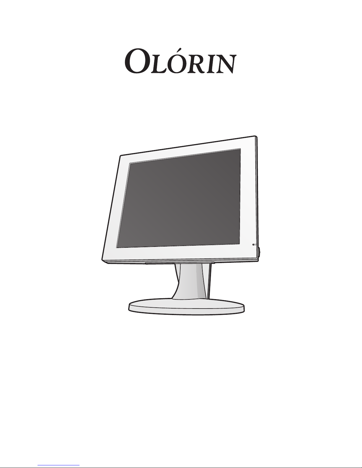
Display User’s Manual
VistaLine & MedicLine
VC190D, MC190D &
MC200D
www.olorin.com
Page 2

2
Page 3

3
1. Preface 4
2. Product features 5
3. Intended use of this product 6
4. Intended markets 6
5. Safety Precautions 7
6. Regulatory Tests and Certications 10
7. Test of medical power adapter 11
8. FCC Information 11
9. Warranty and Limitation of Liability 12
10. Product identication 12
11. Cleaning of the Product 13
12. Disposal of the Product 13
13. Getting started 14
14. How to assemble Panel and Base unit 15
15. Mounting on a wall or LCD arm 16
16. Rotating the LCD Panel 17
17. Connection Method 18
18. Input signals 19
19. How to Operate 20
20. OSD Adjustment Functions 21
21. PerfectLum Calibration Software 24
22. Applicable Signal Timings 25
23. Specications 26
24. Special Considerations for LCD Panels 30
25. Longer life for your monitor 32
26. Troubleshooting 33
27. Reference 34
28. Contact information 35
Contents
Page 4
4
Preface
Thank-you for purchasing this Olorin LCD Monitor.
To get the full benet of the features that this product offers you, it is important that you read this
User’s Manual which, among other things, will explain how to properly install and operate the
monitor. In this user guide there are detailed product specications, explanations for many of
the technical terms used in this manual as well as information on regulatory approvals, cleaning,
service instructions, warranty terms, waste disposal and some other useful information.
It is of utmost importance that you carefully read and follow the safety instructions and
safety notices included in this User´s Manual.
Failure to comply with these instructions could in some instances cause bodily harm to yourself
or other persons and/or un-repairable damage to the product or to other attached devices /
appliances.
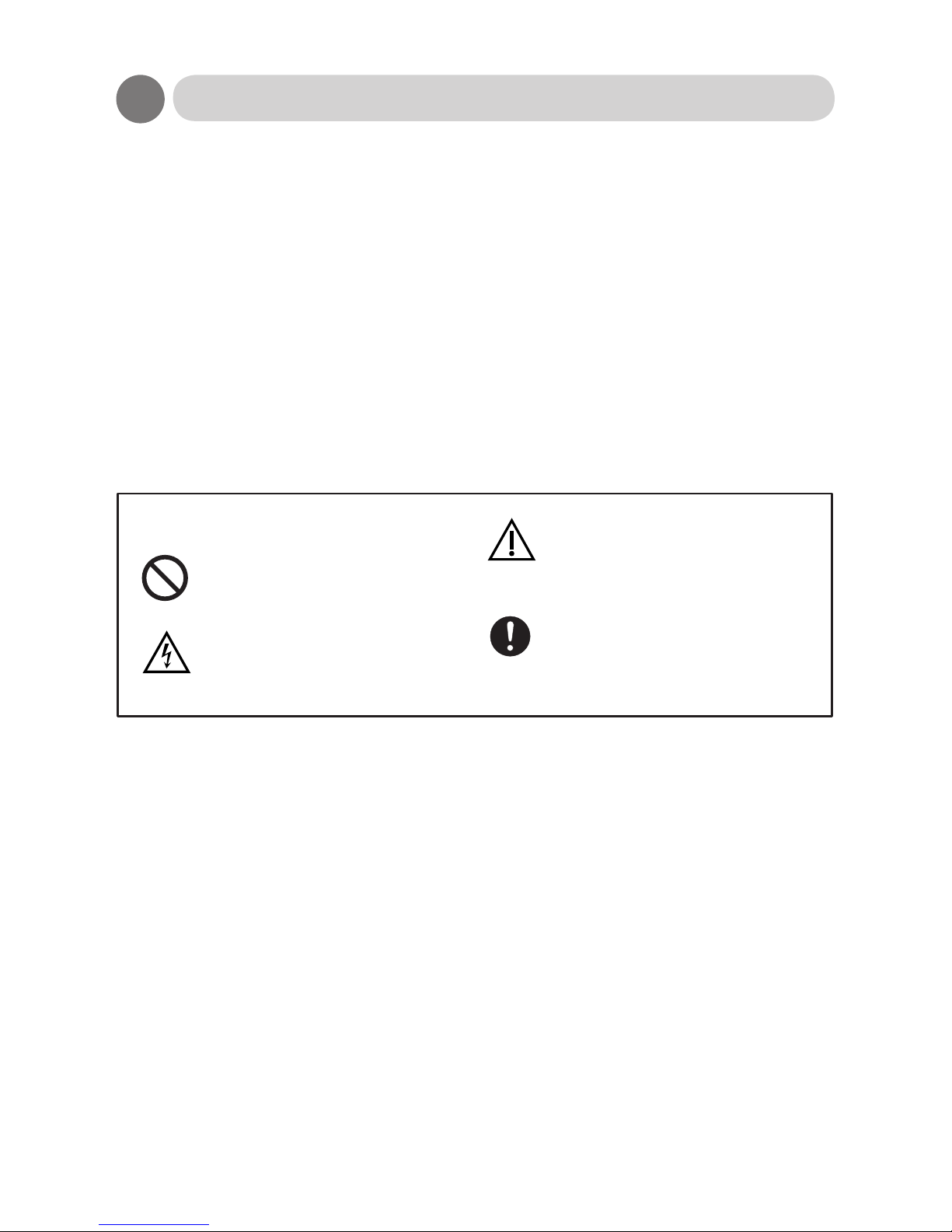
Throughout this manual the following symbols are used to guide you to the proper use of the
product:
Keep this Users Manual in an easy accessible and safe place for future reading of it. If you lose
your copy, you may request a new one by contacting us at our internet home page www.olorin.
com.
Olorin reserves the right to change the specications of this product without any notice. Such
changes could cause the operation of the product to be slightly different from the descriptions in
this copy of the Users Manual.
Windows and MS-DOS are trademarks and/or registered trademarks of Microsoft Corporation in
the United States and/or other countries. VESA is a trademark of the Video Electronics Standard
Corporation. All other product and company names are trademarks of their respective owners.
Copyright © 2012
Symbols
Expresses DO NOT.
Person could be at risk of
severe injury or death.
Person or properties could be
at risk of injury or damage.
Expresses MUST DO.
Warning
Caution
Page 5

5
Product Features
Standard delivery
The product is normally delivered in 2 main parts, which, when mounted together, form a normal
monitor for desktop use.
• a LCD panel with TFT picture element which also contains the lamps for the backlight along
with necessary electronics and cable connectors as well as power connector. These parts are
mounted inside a plastic housing.
• a base unit (stand) to be mounted at the VESA holes at the back of the panel.
For certain applications, when the monitor is to be placed on a wall or built into a desk, then only
the LCD panel part is delivered. In these cases it is quite often delivered with the plastic housing
removed in what is called “open frame”. Certain other options or special mounting components
might have been pre-installed.
When the monitor has been delivered as open frame there is a greater risk to come
in contact with electric parts which could cause harm to yourself or your property. It
should therefore only be handled with special precaution and only by properly trained
service personnel.
Power management
This unit has power management system. The monitor will go into “sleep mode”, where power
consumption is less than 5W, whenever either horizontal or vertical signals or both disappear.
High performance panel element
The color LCD panel used in this product is specically designed for advanced applications such
as viewing digital X-ray images. ALS (Automatic Luminance Stabilization) circuits gives a stable
picture for the life of the product. ALC (Automatic Luminance Control) circuits will automatically
adjust for the decay of the backlight lamps.
Front sensor for calibration and quality assurance
The monitor is equipped with a front sensor used for stabilizing the calibrated luminance. It is also
used for un-attended calibration and quality checks. The monitor is bundled with PerfectLum™
calibration and quality assurance software.
Preloaded DICOM curve
The monitor has a preloaded Barten DICOM curve for use as a plug-n-play X-ray review display.
Ergonomic features
To ease eyestrain on the user, the panel features excellent viewing angles. In addition, the base
unit can be adjusted to t the individual user’s need by adjusting the height and tilt of the monitor.
VESA® standard wall / arm mountings
The unit is compliant with VESA’s 100mm-pitch (75 mm for 12” and 15” monitors) for hanging
tools. The base unit is detachable; the panel can be mounted on a wall or arm according to user’s
enviroment.
Warning
Page 6
6
Intended use of this product
This product has been designed and developed for use as a visual output device for direct
connection to a Personal Computer and PC compatible devices as well as other video generating
equipment, such as cameras. The product will accept industry standard video signals coming over
cables with industry standard type connectors. The product will operate and function properly in
normal ofce environment and under conditions as specied in the Product Specication chapter.
Attempting to use the product for any other purpose than its intended use or
connecting to other devices could cause damage to the product and / or to other
property and equipment. There could also be a risk of bodily harm to yourself or other
persons.
The product operates on 12V (some on 24V) DC power and must be connected thru the AC 100240V, 50-60Hz to12V DC adapter (or 24V DC adapter) which is included with the product. Power
to the adapter should be coming from an ordinary grounded AC 100-240V power outlet.
Never try to connect the product to any other power source than the 12V/24V adapter
delivered together with the product. There would be a risk of electrical shock which
could cause bodily harm, possibly even death. Most certainly such electrical shock will
damage the product.
The product can also be delivered with certain options installed. Such options could be touch
panel or other special accessories.
All other uses of the product, including but not limited to attempts such as;
• connection to other types of power sources
• using other types of mounting or placement of the product
• connection to other devices than those for which the monitor has been
designed.
will void any and all warranties of the product and the manufacturer will not be
responsible or libel for any bodily injury or property damage either directly or
indirectly caused by such non-intended use of the product.
Warning
Warning
Intended Markets
Olorin products are developed primarily for sales and installation in countries within Europe and
North America. The products comply with all regulations and directives issued by the European
Union and by authorities in the United States.
The products are not intended for sales and/or installation in countries, which require
other or additional mandatory approvals than those required by the authorities of the
European Union or the United States.
Consult the product identication label or product specication for regulatory approvals that apply
to this product.
Warning
Warning
Page 7
7
Safety Precautions
It is important that you read through the following notes of Safety Precautions to avoid any
damage to the Product, yourself or other property. Following these precautions will also ensure
that you get the best use of the Product.
DO NOT OPEN THE PRODUCT. There are no user serviceable parts inside. Because
of high voltage inside there is a risk of bodily injury or death. Only authorized and
qualied service personnel should maintain the product.
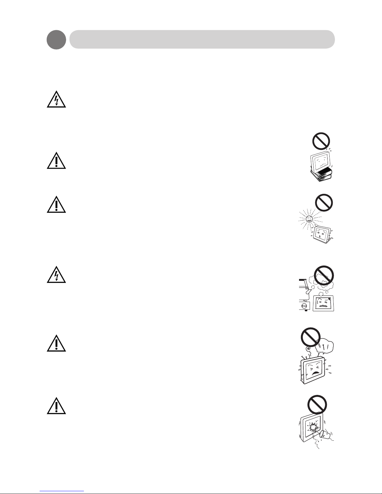
Cautions when setting up
Do not put the unit on unstable places (on a wonky table or in an inclined
place), which might cause injuries if it falls down.
Do not place the unit where it is subject to direct sunlight or near any
heating device. This could cause overheating resulting in damage to
the product and eventually causing a re.
Cautions when using
Do not put the unit in such a place where there is bad air circulation,
dust, humidity, oily smoke or steam. It may lead to a re.
Do not put any metal materials or ammable foreign objects into the
unit through the vent holes. It may lead to electric shock and/or re.
Immediately disconnect the unit from the power outlet and contact your
local re-seller for service.
Scratching or hitting with hard objects may damage the unit.
Warning
Caution
Warning
Caution
Caution
Caution
Page 8
8
Warning
Safety Precautions
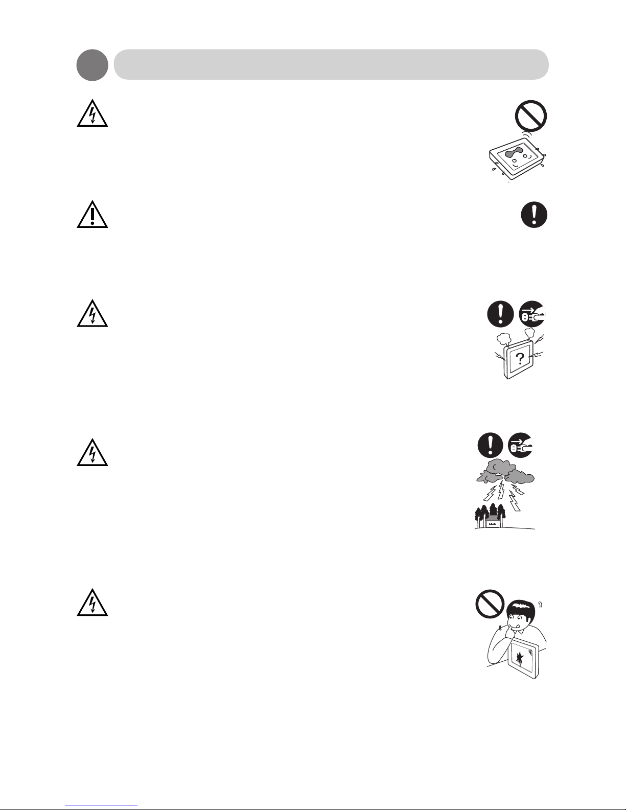
Do not use the unit turned over on its back, put on its side, or upside
down. These positions may cause the heat that the unit generates to
accumulate inside the unit. Such overheating can cause damage to the
product and eventually start a re.
When using the unit for several hours, you should take a 10-15 minute
break every hour to reduce eyestrain. Failure to do so could cause injury to
your eyes.
Abnormal circumstances
In case of any abnormality such as odor, sound, and overheat taking
place, immediately turn off the power and disconnect the plug from
the outlet. Continuing to use the unit under such condition may lead to
electric shock and/or re. For assistance contact your local re-seller.
In the event of thunder, immediately turn off the power and
disconnect the plug from the outlet. Lightning strikes may cause
electric shock and/or re.
In the event of broken panel and leaking liquid crystal, do not inhale,
swallow, or touch the liquid crystal. It may cause you to get poisoned
and/or having a skin irritation. If you put it in your mouth, immediately
gargle with water and contact a doctor to get a checkup. In case of
getting it on your skin and/or cloth, wipe it off with alcohol and rinse
them.
Warning
Caution
Warning
Warning
Page 9
9
Safety Precautions
Maintenance
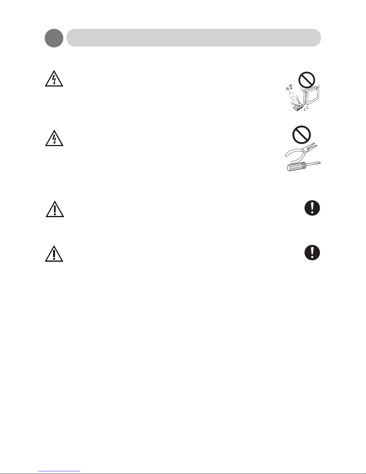
Do not remove the plastic cabinet. There are high voltage parts inside
that may lead to electric shock. Ask a re-seller for adjustment and
inspection.
Do not remodel or repair. It may lead to re, electric shock, or injuries.
Clean the dust inside the display once a year. The dust that accumulates
inside the unit may lead to re. Ask a re-seller for adjustments and
inspection.
Disconnect the plug from the outlet when you do not use the unit for a
prolonged period.
Warning
Caution
Warning
Caution
Page 10
10
Regulatory Tests and Certications
All Olorin products have normally been tested to comply with all mandatory Regulatory
requirements for the markets where the products are sold. Approvals are listed by each
Regulatory Agency under the name of the manufacturer and model number as specied on the
Product Identication Label. Copies of such approvals can be requested by contacting Olorin AB
via www.olorin.com.
Approvals applicable for this product is listed in the Product Specication section of this
manual.
Tests and Approvals for VistaLine Series
Each product in the VistaLine series has been tested as an IT-category product for normal ofce
environment and for use as a desktop monitor. They comply with the following standards and
regulations:
• CE for use within the European Union member states
• UL for use in the United States
• FCC for use in the United States
• WEEE for use within the European Union member states
• RoHS for use within the European Union member states
Tests and Approvals for MedicLine Series
Each product in the MedicLine series has additionally been tested for risk of electrical shock and
to comply with
• MDD directive 93/42/EEC class 1 for the European Union member states
• EN60601-1, EN60601-1-2
• IEC 60601-1
Some of the products have also been tested to comply with:
• UL 60601-1
• CAN/CSA C22-2 No. 601-1
Under these directives and regulations, MedicLine products are complying with the requirements
for a Class 1 product with continuous mode of operation. The monitor must not be in direct contact
with a patient.
Using any other 12V/24V adapter than the medical approved one delivered with the
product or connecting this to a non-grounded power outlet voids the approval.
Before taking the product in use, the person installing it must test that the grounding
of the monitor complies with the impedance requirements of the country where it is
being installed.
When using at 240 V in the United States, supply must be from center-tapped, 240 V,
single phase circuit.
Warning
Warning
Warning
Page 11

11
FCC Information
FCC (U.S. Federal Communications Commission)
This equipment has been tested and found to comply with the limits for a Class B digital device,
pursuant to part 15 of the FCC Rules.
These limits are designed to provide reasonable protection against harmful interference in a
residential installation. This equipment generates, uses, and can radiate radio frequency energy,
and if not installed and used in accordance with the instructions, may cause harmful interference
to radio communications.
However, there is no guarantee that interference will not occur in a particular installation. If this
equipment does cause unacceptable interference to radio or television reception, which can
be determined by turning the equipment off and on, the user is encouraged to try to correct the
interference by one or more of the following measures:
• Reorient or relocate the receiving antenna.
• Increase the separation between the equipment and receiver.
• Connect the equipment into an outlet on a circuit different from that to which the receiver is
connected.
• Consult your re-seller or an experienced radio/TV technician for help.
FCC Warning:
To assure continued FCC compliance, the user must use a grounded power supply cord and the
provided shielded video interface cable with bonded ferrite cores. Also, any unauthorized changes
or modications to this monitor would void the user’s authority to operate this device.
Test of medical power adapter
The power supply is Class I. Protective earthed parts are only located inside the power supply
enclosure and therefore are not accessible. The accessible parts of the enclosure and output
are DOUBLE INSULATED from all mains voltage electrical parts. Ground continuality test is not
relevant.
Leakage test of the adapter is made by having the measurement equipment connected to the AC
plug, no need to open the plastic enclosure.
Page 12

12
Warranty and Limitation of Liability
Warranty
For details of the warranty please see the separate warranty document included with this product.
Limitation of Liability
Olorin AB, including any of its afliates, manufacturing partners and sales agents, is not liable for
any claim for damages including, but not limited to, loss of business prots, disruption of business,
change or loss of saved data, when damage is arising from
• re, earthquakes, actions taken by any third party, any other accidents, intentionally
or negligently, improper use of the product by the user, or any use under other abnormal
circumstances,
• the use or inability to use this product,
• the use for other purposes than the intended use as described in this document
• malfunctions caused by the combination of connected devices
Product identication
Afxed to the panel part of the product is a Product Identication Label. It is normally afxed in the
connector compartment. This label contains the following information:
• Olorin logo and web address
• Product Family name (i e Olorin VistaLine VC190D)
• Manufacturers product number
• Part number
• Serial Number
• Power information
• Symbols for Regulatory approvals
• WEEE symbol for disposal of the product
• Manufacturers name
• Country of Origin
Page 13
13
Cleaning of the Product
Be careful when cleaning the plastic housing of the panel so that no liquid or other
objects will drip down into the product through the ventilation holes. This could cause
electric shock and damage the product.
Normal dust and lint particles can be easily wiped off with a soft cloth tissue.
For grease or dirt that is more rmly xed to the product, the use of a soft and dry micro ber
based cloth tissue will normally remove it all.
You can also use a mild liquid detergent mixed with water for cleaning together with a soft cloth
tissue. This will clean both the cabinet and the LCD panel well. For the LCD panel you can also
use isopropyl alcohol based liquids (without abrasive) or non-ammoniac glass cleaner.
When cleaning the LCD panel you will get the best result if you clean the panel when its surface
has cooled down to normal room temperature. On a warm panel the liquid evaporates too quickly
leaving traces of the cleaning. Afterwards wipe the surface dry with another soft cloth tissue.
When cleaning the cabinet do NOT use thinner, benzene or alcohol as these might
damage the plastic and cause the paint to peel off. Do NOT use organic solvent such
as acetone and toluene when cleaning the panel.
If you use any liquid for cleaning you must rst un-plug the power to the monitor and
not connect it again until you are certain that all the liquid particles have evaporated.
Failure to do so could result in electric shock.
Do not use any tools with hard or sharp material for cleaning. The panel can very
easily be scratched or damaged from such tools.
Do not press hard on the panel when cleaning. This could cause damage to the LCD
panel element.
Caution
Warning
Caution
Caution
Do not dispose of the unit with general wastes.
The monitor has been manufactured to comply with the EU directive on RoHS (Reduction of
Harmful Substances) but even so the LCD panel contains a small amount of mercury and the
monitor should therefore be disposed of according to local laws. Please get information from your
local re-seller how collection is handled in your country. For countries that are members of the EU
the WEEE directive applies and proper marking is on the product label afxed to the monitor.
Disposal of the Product
Warning
Page 14

14
Getting started
Before operating this monitor, please make sure that all items listed below are present in your
delivery.
Standard Items
• The LCD monitor panel
• User’s manual
• Warranty booklet
• AC/DC adapter
• AC Power cord
• DVI to DVI cable
Optional Items
• The Base unit with 4 Screws and Screwdriver
• CD-ROM with PerfectLum™ software
If any of the above items are found missing or if you wish to order the optional items, please
contact your reseller.
Page 15
15
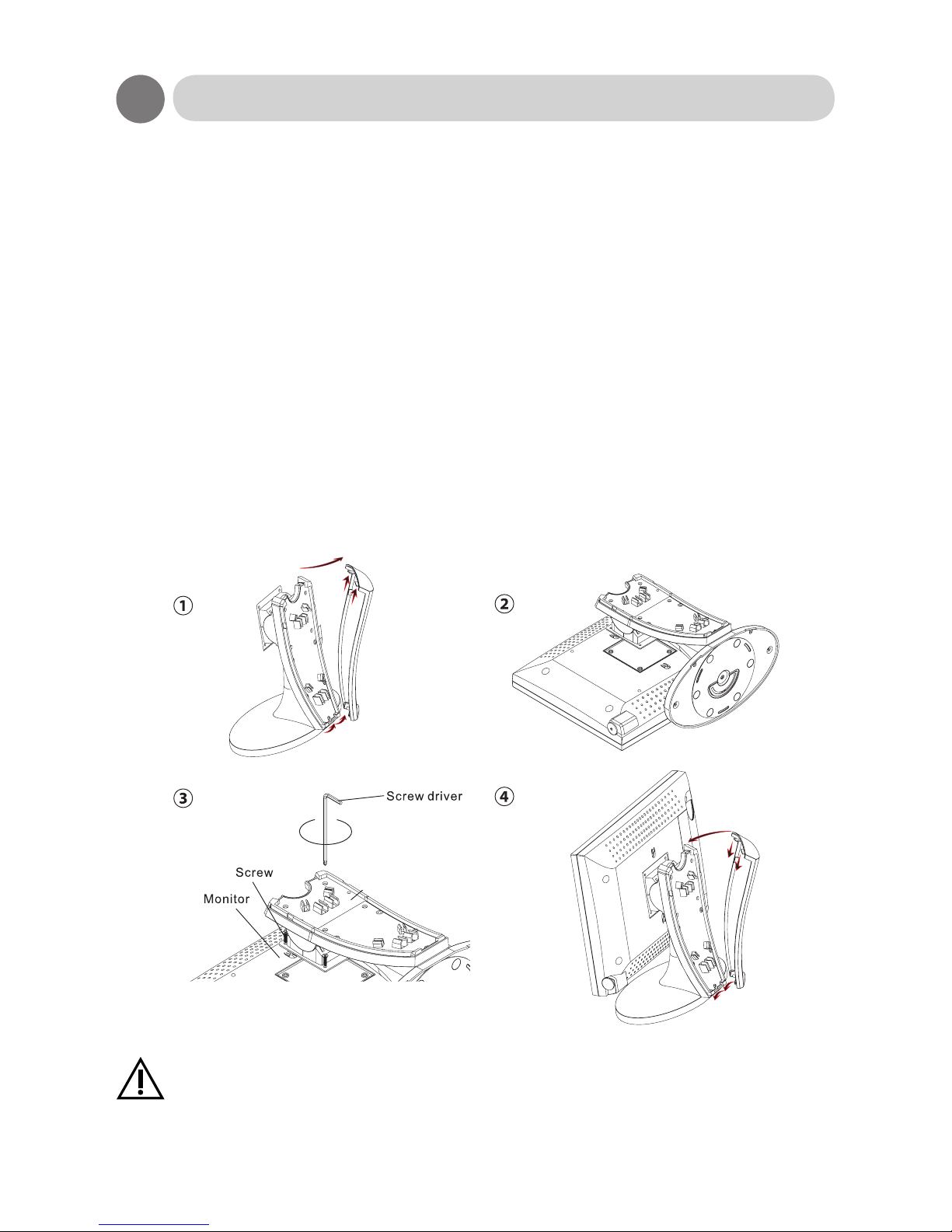
How to assemble Panel and Base unit
The product normally comes in 2 cartons and you need to assemble the panel and the base unit.
A screwdriver and proper screws are included in the box for the base unit.
1. Remove the back of the base unit by grabbing it rmly at the top and pulling it up and
backwards.
2. Place the monitor with the front down on a level surface. Make sure that there are no objects
on the surface that could damage the panel element. It should be placed so that the OSD
wheel is at the lower left corner seen from yourself.
Place the metal plate onto the VESA mounting cut-out on the back of the panel. Hold the
bottom of the base unit towards yourself.
Test that you can swing the base unit to the left so that swivel between Landscape and
Portrait will be correct.
3. Locate the holes in the back of the base unit through which you can stick the screwdriver to
reach and put the 4 screws in place.
4. Remount the back cover.
If you mount any device using these 4 holes on the back of the panel you must not
use use screws longer than 10 mm. Longer screws will cause damage which is not
covered by the product warranty.
Caution
Page 16
16
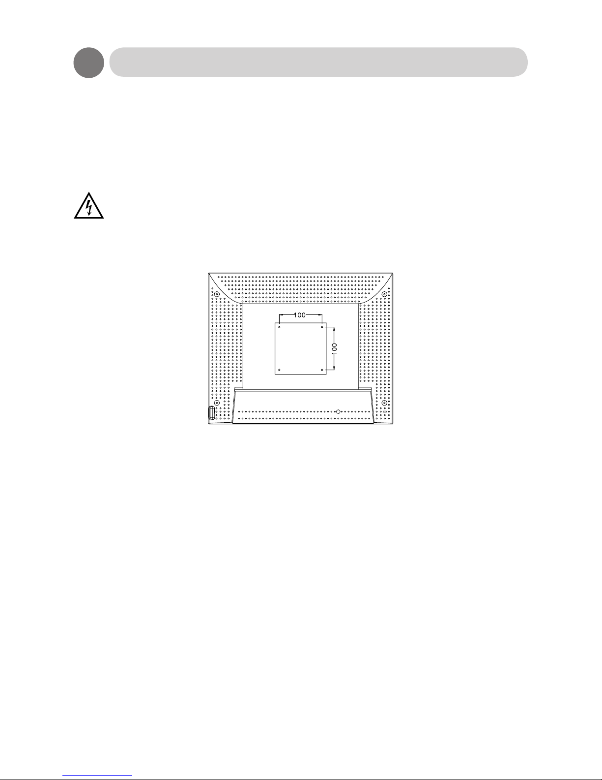
Mounting on a wall or LCD arm
The Monitor has Video Electronics Standards Association (VESA) standard mounting holes
tapped into the rear panel. The standard holes are M4 set 100 mm (for 17” and larger monitors) or
75 mm (12” and 15” monitors) apart.
If you intend to mount the monitor on the wall, we strongly recommend that you use wall mount
kits with attached M4*10mm screws and which can hold a load of more than the weight of the
monitor. Ensure it is securely and safely installed.
If you mount any device using these 4 holes on the back of the panel you must not
use use screws longer than 10 mm. Longer screws will cause damage which is not
covered by the product warranty.
Warning
The position of the connectors can vary between models and they may or may not be covered
with a ap.
Page 17
17
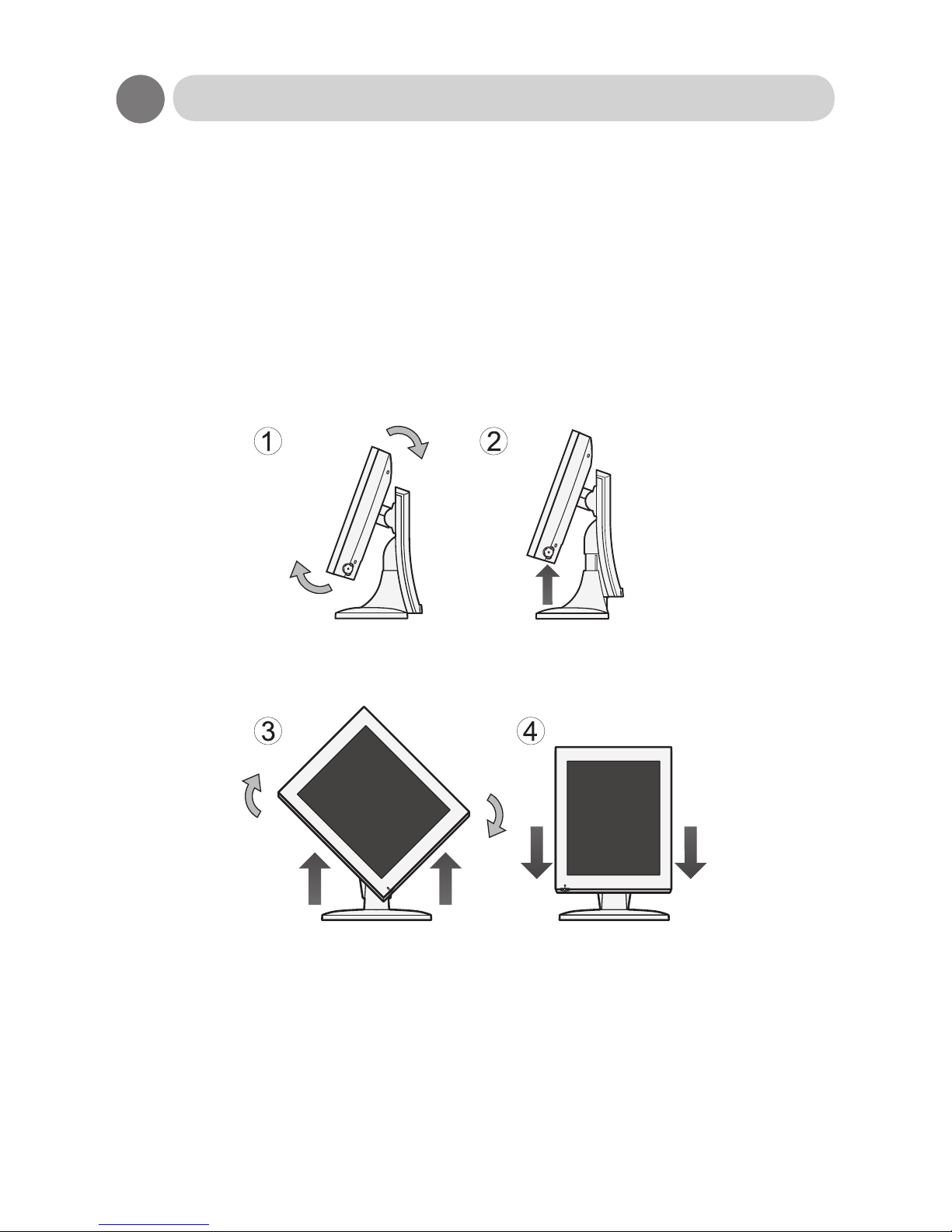
Rotating the LCD Panel
When setting the LCD display to vertical display (portrait orientation), lift the LCD panel to the top
of the base unit as shown in the gure below and rotate it by 90 degrees.
Procedure
1. Tilt the LCD panel upward.(Perform this procedure before sliding the panel upward.)
2. Lift the LCD panel to the top.
3. Rotate the LCD panel by 90 degrees.
4. Reposition the LCD panel to the bottom while in the vertical position (portrait orientation).
Display in portrait orientation
Pivot® software or graphics card that enables portrait orientation is necessary.
4
Page 18
18
Connection Method
No tools are required to connect the LCD monitor to your PC or other device. Simply follow the
instructions outlined in the next few pages.
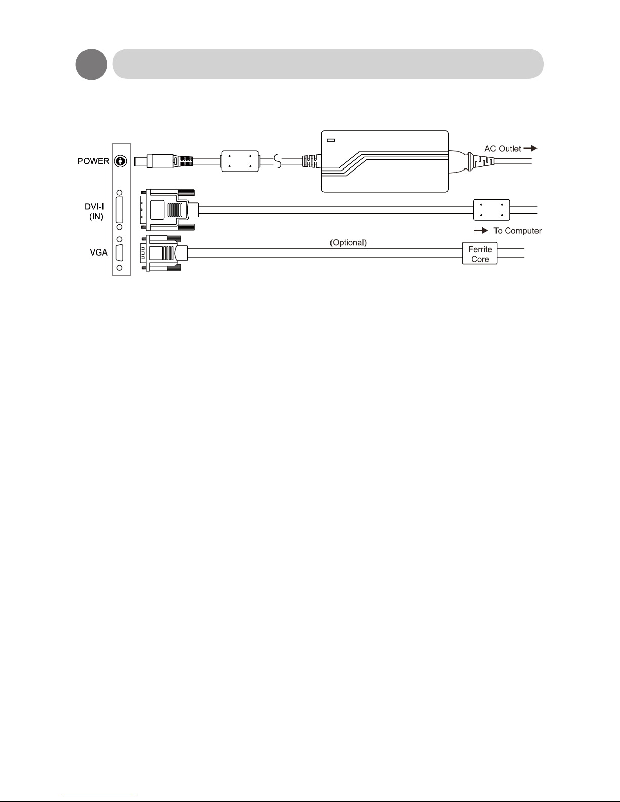
Connectors for the signal cables and power are located on the back of the panel behind the cover
lid. Please refer to the diagram on the next page for the connector conguration.
Connect Power Adapter and Cable
Connect the round shape plug end of the AC/DC adapter to the DC Power input connector of the
LCD monitor. Connect the female end of the power cable to the AC power input receptacle on the
AC/DC adapter. Then, plug the male end of the power cable into an grounded AC outlet.
Make sure you use the AC to DC adapter delivered with the product.
Connect Signal cable
On next page you can see which input connectors there are available on your monitor and which
cable you should connect depends on your source for the input signal.
VGA, DVI, HDMI or Displayport output from a PC
If your source is VGA (analog) then use either a VGA to VGA cable for connection to the VGA
connector or a VGA to DVI-I cable for connection to the DVI-I connector on the monitor.
If your source is DVI (digital) then use the DVI-DVI cable supplied with the monitor and connect to
the DVI-I connector on the monitor.
If your source is HDMI or Display-Port then you need a converter from HDMI or Display-Port to
DVI. Then you connect the DVI-DVI cable between the DVI-I connector on the monitor and the
converter. There are also available HDMI or Display-Port to DVI cables that can purchased from
your local reseller.
When you disconnect the cord /cables, be sure to hold the connector and not the
cable itself. Also make sure you use cables and connectors of high quality.
Caution
Caution
Page 19
19
Input signals
Connections, 19” and 20”
Page 20
20
How to Operate
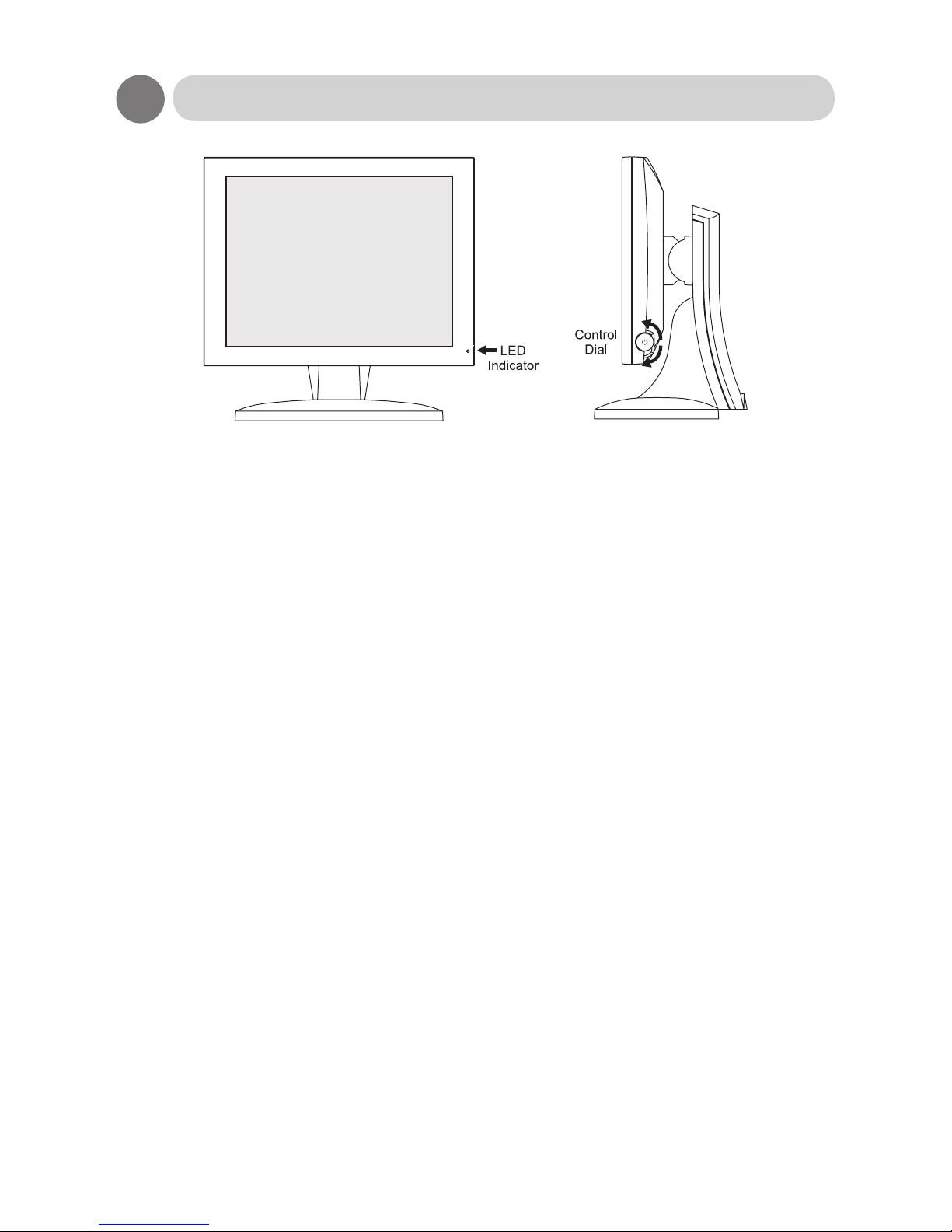
Control Dial
The Control Dial is a multi-functional device located behind the LED Indicator on the right side of
the front bezel. It has three movements-rotate upward, rotate downward and press inward as a
button.
1. Power On/Off
Press the Control Dial to power the unit on from the off stage (the display is off). To turn the
power off, press the Control Dial and hold for at least 1 second until the display turns off.
2. OSD Control
While the monitor is on (image on the screen), pressing on the Control Dial activates the
OSD. While the OSD menu is active, use the three way movements of the Control Dial to
adjust the monitor.
Rotate Downward: Move Up/Right, Increase, Larger, More
Rotate Upward: Move Down/Left, Decrease, Smaller, Less
Button Press: Execute, Do, Save
3. Change of Brightness Setting
If you rotate the Control Dial without rst having clicked to enter the OSD, then it will change
the brightness setting. On some models it will do so in a quick way by adjusting with larger
steps in the bright area and gradually lower values towards the dark area. This function is
disabled when the monitor is in Barten or Calibration mode.
LED Indicator
This LED indicator turns green when the power is switched ON and the power cord is properly
attached. It turns amber when the monitor goes into a power saving mode (Active Off). On some
models it will be switched off entirely after 10 minutes to avoid that the lamp will distract your
vision.
Page 21

21
OSD Adjustment Functions
PreVu™ On-Screen Display
The LCD monitor features a PreVu™ On-Screen Display(OSD) menu with easily identiable icons
designed to make adjusting your monitor display settings a more user-friendly process. When
highlighted, the icon illustrates the control function and a brief instruction to assist the user in
identifying which control needs adjustment.
The OSD menu is activated by pressing the Control Dial inward and you can select and adjust
the function of your choice by rotating and clicking the Control Dial. The main menu displays a
list of control icons and the current video input mode. Rotate the dial to move the highlights to
the control you would like to adjust, then press the Control Dial inward to select that control or
to activate that function. Depending on the control you selected, a submenu of the control with a
status bar will appear. The status bar indicates in which direction, from the factory preset, your
adjustments are being made. Rotate the Control Dial to adjust the control.
When you have nished making the adjustments, the setting is saved automatically by exiting
the control function. If you do not touch the control dial for 20 seconds, the OSD is automatically
exited saving your current settings.
Menu descriptions
The LCD monitor is capable of accepting DVI and VGA signal inputs and therefore has two
different sets of OSD control functions.
Depending on your input source and also depending on which color mode you have selected
there are some functions that are not necessary, cannot be executed or are locked out to comply
with certain standards. You will then encounter the message “Not Available” when you try to select
such functions.
The following charts show the function tree and brief explanations of the functions.
Page 22

22
Charts of OSD Adjustment Functions
Main menu
Exit Close the OSD screen
Auto setup *1 Image OK? If you answer YES then return to Main Menu. If you answer NO, proceed
to Clock / Phase menu
Brightness Adjust brightness level. See also special note in “How to Operate” section
on brightness adjustment in special situations.
Contrast Adjust contrast of the monitor. Not active when Clear base Barten or
Calibration color mode has been selected.
Display *1 Exit Return to Main menu
H. Position Adjust horizontal screen position
V. Position Adjust vertical screen position
Color mode Exit Return to Main menu
Normal Color Temp Selecting this control allows you to select color temperature of Cool,
Neutral, Warm or User.
Cool Selects a cold color temperature of about 9000K.
Neutral Selects a neutral color temperature of about 6500K.
Warm Selects a warm color temperature of about 5500K.
User In a separate sub-menu you can set individual values for Red, Green
and Blue.
Clear base Barten A special color mode intended for viewing of X-ray pictures. Has a
preset grayscale curve in accordance with the DICOM standard and
automatically sets the monitor to brightness of about 170 candela and
color temperature of about 6500K. When set to this mode the OSD
functions for Brightness and Contrast are disabled. The ALC function will
automatically adjust brightness for the decay of the backlight lamps. It
also locks ALS to ON.
Calibration A special color mode intended for viewing X-ray pictures. Using
PerfectLum software, the user can upload a calibrated grayscale curve in
to the LUT of the monitor. When set to this mode the OSD functions for
Brightness and Contrast are disabled. It also locks ALS to ON.
Clock/phase *1 Exit Return to Main menu
Clock For analog VGA only. Fine tune video signal for positioning of the picture
horizontally on the screen
Phase For analog VGA only. Adjust Phase frequency to control ickering or
horizontal waves on the screen.
Continued on the next page...
Page 23

23
Main menu continued
Management Exit Return to Main menu
OSD Display Exit Return to Management menu
OSD H. pos Move position of the OSD display horizontally
OSD V. pos Move position of the OSD display vertically
Language Select language for OSD. Returns to Main Menu and will from then
on show the OSD in the selected language. You can choose between
English, French, German, Italian, Spanish or Japanese.
Source Exit Return to Management menu
VGA Display signals from VGA connector (15-pin Mini D-sub). In VGA input, it
supports Sync-on green and the interlace timing can be displayed.
DVI-I Digital Display signals from DVI connector. (29-pin DVI).
DVI-I Analog Display signals from DVI connector. (29-pin DVI). In VGA input, it supports
Sync-on green and the interlace timing can be displayed.
Recall If you execute Recall the monitor will be reset to values that are default
values at time of delivery.
Lum stable Automatic Luminance Stabilization (ALS) has been developed for Barten
and Calibration color modes and will automatically be set to ON for these
modes. The setting cannot be changed by the user. ALS will stabilize
brightness at calibrated luminance value regardless of the temperature
inside the monitor or its surrounding. It will also quickly ramp up to this
luminance setting when the monitor is switched on. If you use Normal
Color Mode, then you can switch it ON or OFF but the recommendation is
to set it to OFF.
Operation hours Selecting this submenu will show how many hours the monitor has been
used.
*1 These functions are only available when the monitor input Source is analog.
Charts of OSD Adjustment Functions
Page 24
24
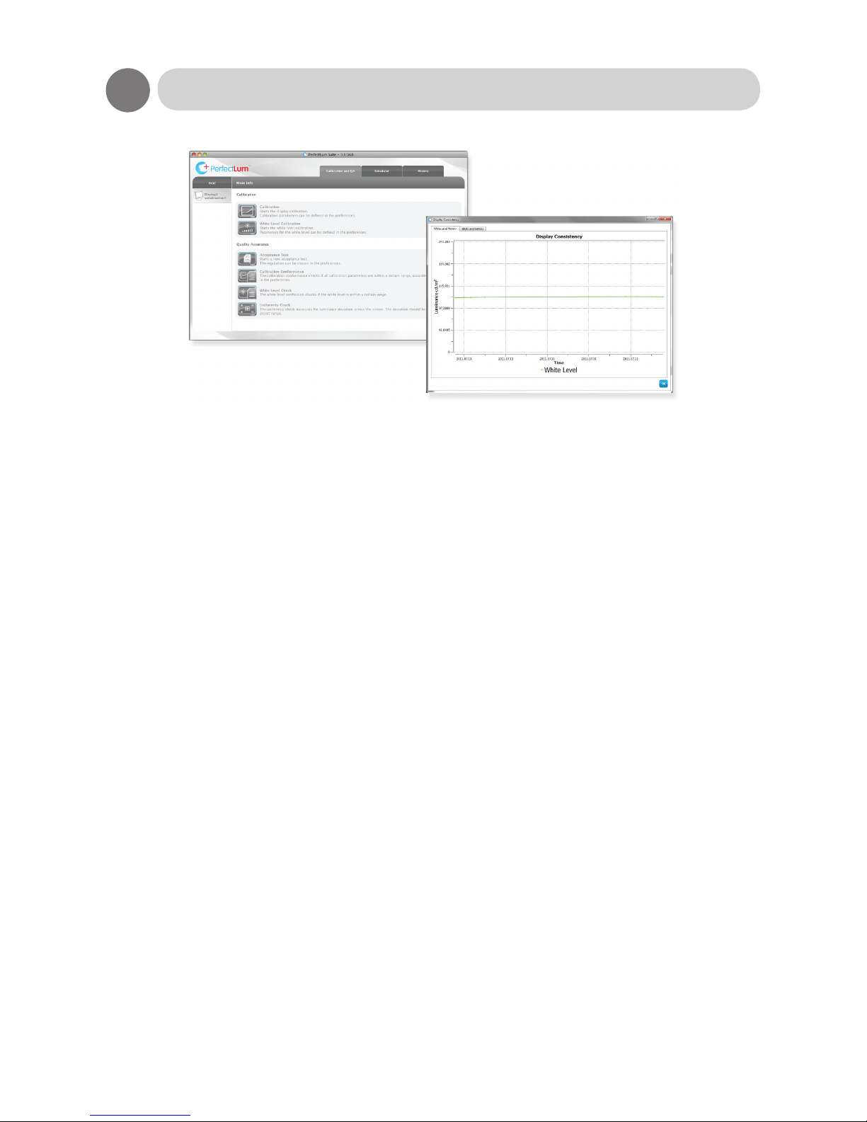
PerfectLum is software to calibrate and verify medical displays that are used for Diagnostics or
viewing of medical images. It is developed in a cooperation between Qubyx Ltd (www.qubyx.com)
and Olorin AB.
PerfectLum conforms to all common standards for DICOM calibration; this includes NEMA DICOM
14 GSDF, AAPM TG18, DIN6868-57, JESRA X-0093 and IEC-62563-1. PerfectLum can also be
used to perform conformance tests for quality assurance against the current standard.
Internal LUT
Olorin monitors with front sensor can be calibrated with PerfectLum software and have the values
saved in its internal LUT (Look-up Table). Since this LUT is based on 10-bit graphic (1024 levels
of grey), the image presented is very smooth when compared to 8-bit graphic (256 levels of grey).
Reports and diagnostics
PerfectLum saves all history for calibrations and quality assurance tests. The history is visualized
in graphs and can be exported to printable reports. The software has a backup function that
makes sure everything can be stored safely.
PerfectLum Remote Management Server
Remote Management Server is an optional feature to PerfectLum. Remote Management enables
the user to centralize and schedule all of their calibration tasks and quality assurance tests over
a web interface. This means that Olorin monitors with internal LUT and front sensor do not need
local assistance, instead everything can be controlled automatically via a remote computer.
System compatibility
PerfectLum is compatible with all major graphics card and external sensor (used for controlled
measurements) manufacturers. This means that an upgrade of existing hardware is often
unnecessary. PerfectLum supports all the latest versions of Windows and Macintosh operating
systems: Windows 7, Vista, XP, 2000 32/64 and Macintosh OS X 10.4 and up.
PerfectLum™ Calibration Software
Page 25
25
Applicable Signal Timings
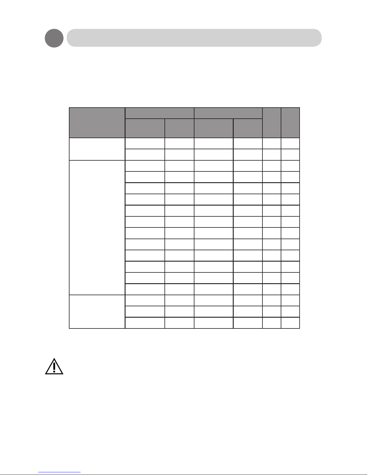
The display may not work correctly with timings other than listed below.
For 19”, the display mode, and UXGA 1600*1200, is a downscaled Pseudo-display.
Caution
◎ :
Recommended timing
○ :
Applied timing ∆ : Pseudo-display timing
Display mode
Resolution Frequency
19" 20"
Horizontal Vertical
Horizontal
(kHz)
Vertical
(Hz)
VGA
720 400 31.5 70
○ ○
640 480 31.5 60
○ ○
VESA
640 480 37.9 72
○
∆
640 480 37.5 75
○
∆
800 600 35.1 56
○ ○
800 600 37.9 60
○ ○
800 600 48.1 72
○
∆
800 600 46.9 75
○
∆
1024 768 48.4 60
○ ○
1024 768 56.5 70
○
∆
1024 768 60.0 75
○
∆
1280 1024 64.0 60
◎ ○
1280 1024 80.0 75
○
∆
1600 1200 75.0 60 ∆
◎
MAC
640 480 35.0 67
○ ○
832 624 49.7 75
○
∆
1024 768 60.2 75
○
∆
Page 26

26
Specications
VC190D & MC190D
Display Screen size, Format 19” (376x301 mm), 5:4
Brightness, candela/m2 300 cd/m2
Contrast 1300:1
Resolution (Megapixel) 1280x1024 (1,3 Mpix)
Response time 20ms
Viewing angles, H/V 178/178
Color depth 16,7M
Panel type MVA
Backlight type CCFL
Environmental Operating Storage
Temperature, Celcius +5 to 40 C -20 to 60 C
Humidity (non-condensation) 20 to 80%RH 20 to 80%RH
Air pressure 697 to 1060 hpa 187 to 1060 hpa
Input signal Connections VGA, DVI-I
DDC DDC-2B, DDC/CI for calibration
Power Power supply External 12V
Power consumption Max 50W (5W in stand-by)
Functionality Automatic adjustment Yes (via OSD)
OSD for settings Yes
Speakers No
Luminance stabilization ALS, ALC
Pivot Yes, graphics card dependent.
Protective glass No
Internal LUT Yes, 10-bit.
Internal LUT for calibration Yes, please view ”Charts of OSD Adjustment Functions”
DICOM pt. 14 preset Yes, Clearbase Barten 170 cd/m2
International standards Medical certicates, *1 IEC60601-1, EN60601-1, EN60601-1-2, UL60601-1,
CAN/CSA C22-2 No. 601-1
IT certicates UL/cUL, FCC-B, CE, WEEE, RoHS
Warranty Replacement warranty Two (2) years
*1 Only applies to MC190D
Page 27
27
Specications
VC190D & MC190D
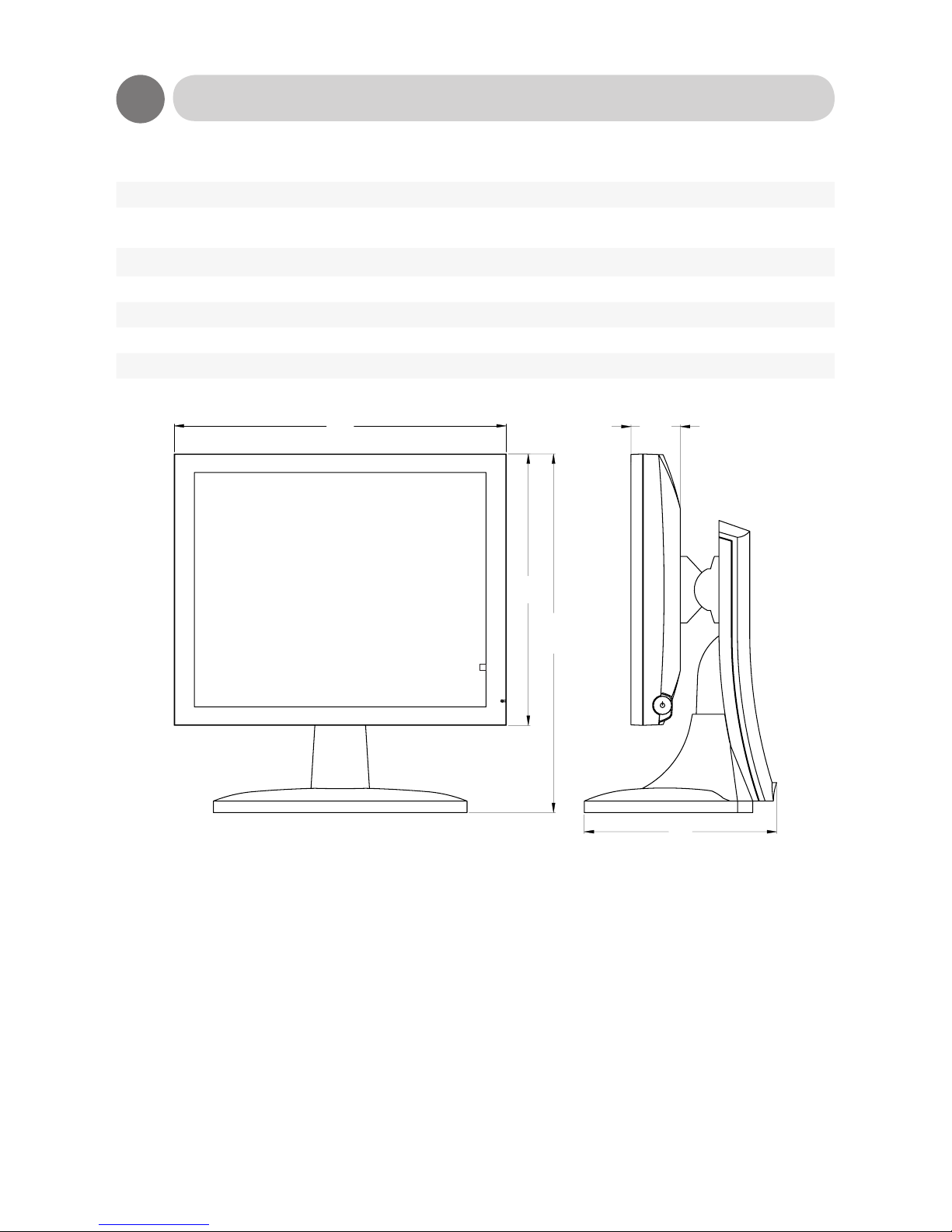
Appearance Net. weight 8,4kg (w/ base unit), 5,7kg (w/o base unit)
Measurements (WxDxH) 431 x 467 x 239 mm (w/ base unit)
431 x 353 x 64 mm (w/o base unit)
Product color Graphite grey (standard) or white (optional)
Base unit Height adjustable Yes
Tilting and swivel Yes
Mounting Kensington lock Yes, prepared.
VESA standard Yes, 100 mm
431
239
64
353
467
Please note that values for Brightness, Contrast, Response time and Viewing angles are nominal
values. Due to delicate manufacturing techniques, these values can be different for each
individual monitor.
Page 28

28
Specications
MC200D
Display Screen size, Format 20,1” (408 x 306 mm), 4:3
Brightness, candela/m2 300 cd/m2
Contrast 800:1
Resolution (Megapixel) 1600x1200 (2 Mpix)
Response time 14ms
Viewing angles, H/V 178/178
Color depth 16,7M
Panel type IPS
Backlight type CCFL
Environmental Operating Storage
Temperature, Celcius +5 to 40 C -20 to 60 C
Humidity (non-condensation) 20 to 80%RH 20 to 80%RH
Air pressure 697 to 1060 hpa 187 to 1060 hpa
Input signal Connections VGA, DVI-I
DDC DDC-2B, DDC/CI for calibration
Power Power supply External 12V
Power consumption 60W (5W in stand-by)
Functionality Automatic adjustment Yes (via OSD)
OSD for settings Yes
Speakers No
Luminance stabilization ALS, ALC
Pivot Yes, graphics card dependent.
Protective glass No
Internal LUT Yes, 10-bit.
Internal LUT for calibration Yes, please view ”Charts of OSD Adjustment Functions”
DICOM pt. 14 preset Yes, Clearbase Barten 170 cd/m2
International standards Medical certicates IEC60601-1, EN60601-1, EN60601-1-2, UL60601-1,
CAN/CSA C22-2 No. 601-1
IT certicates UL/cUL, FCC-B, CE, WEEE, RoHS
Warranty Replacement warranty Two (2) years
Page 29
29
Specications
MC200D
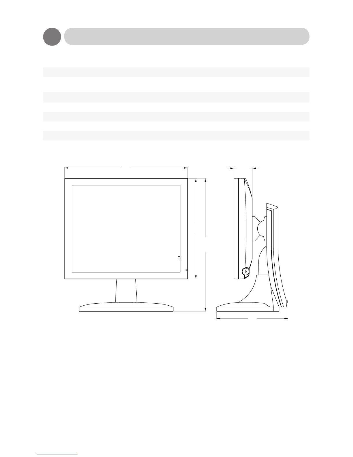
Appearance Net. weight 9,3kg (w/ base unit), 6,6kg (w/o base unit)
Measurements (WxHxD) 473 x 476 x 241 mm (w/ base unit)
473 x 377 x 76 mm (w/o base unit)
Product color Graphite grey (standard) or white (optional)
Base unit Height adjustable Yes
Tilting and swivel Yes
Mounting Kensington lock Yes, prepared.
VESA standard Yes, 100 mm
473
241
76
377
476
Please note that values for Brightness, Contrast, Response time and Viewing angles are nominal
values. Due to delicate manufacturing techniques, these values can be different for each
individual monitor.
Page 30

30
Special Considerations for LCD Panels
Manufacturing of LCD panels is very delicate with large panel elements being manufactured in
one unit and then cut to smaller sizes to be used in different products. In addition a panel consists
of several layers of components (back-light lamps, diffusers, electronics and color lters). There
are different technologies used with each having its advantages and disadvantages resulting in
end user products with different specications even when taken from the same manufacturing
batch. Below are explanations to some observations that can be made and which are not
considered defects since they are merely problems inherent in the technology of LCD monitors.
Over time, the performance of the panel will also change.
Native resolution
All panels have a xed number of pixels in
both horizontal and vertical directions. For
instance is a 19” panel normally built with
1280 pixels horizontal and 1024 vertical giving
a native resolution of 1280x1024. At this
resolution you will get the sharpest picture and
it is therefore recommended that you use the
native resolution. Thru scaling technologies it is
possible to use other resolutions but the picture
will be less sharp. Some text will appear to
have shadows.
Native color temperature
Most commonly LCD panels are manufactured
to have a color temperature of 6500K (Kelvin
degrees) for full white picture. The color
temperature can vary with shade of grey being
showed. For instance it could be 7500K at
50% grey and more than 9000 at 90% grey.
For an individual panel the color temperature
at full white can also vary by +/- 15%. Inside
the panel there is a color lter and over time
this will age and become more yellow in its
color tone. Therefore, over time, the color
temperature will gradually go lower so that at
full white it could come down to 5000K.
Typical values
In product specications there are values for
brightness, contrast, view angles etc. The
values are given as “typical values” meaning
that actual value for any given product can vary
by up to 20% from this value. For instance,
a product specied to give 300 candela as
typical maximum value for brightness may
for individual samples vary from 240 candela
to 360 candela. The values specied are for
a new product. Due to wear of the backlight
lamps the values will change over time and
gradually become lower.
Uniformity and Mura patterns
Depending on the placement of the backlight
lamps, how many they are and the size of
the panel the brightness over the entire panel
will vary by up to 20%. Generally the highest
brightness is in the centre of the panel and
becoming gradually lower towards the outer
edges. This does not follow a linear curve
and there might also be “areas” on the screen
where there is a noticeable difference in the
uniformity. Such clouded areas are referred
to as “Mura” and are more related to the
panel itself than to the backlight. These Mura
patterns are different in size and shape and are
color and grayscale dependent since they are
a result from deterioration of the liquid crystal
alignment layer. Mura is most commonly
caused by long term operation under high
ambient temperature and is a phenomenon
that cannot be repaired.
Non-performing pixels
Each pixel on the panel actually consists of 3
sub-pixels (one for each of Red, Green and
Blue). A 19” panel with 1280x1024 therefore
has almost 4 million sub-pixels. It can happen
that a pixel can get stuck in ON status (bright
pixel defect) or in OFF status (dead pixel
defect) or in an in-between status (low bright
pixel defect). Usually such defects only affect
a sub-pixel and not an entire pixel. The defect
can therefore only be seen at certain color
settings. The ISO 13406-2 standard species
how many pixel defects that are acceptable
before an entire panel will be considered faulty.
Page 31

31
Olorin products are warranted to follow this
standard as a Class II product.
Image sticking
If the same image is shown for a long period of
time there is a risk for “image sticking”. This is
a result of that the thin lm transistors will get
stuck in a certain position and continue to show
that image even when a new image is sent to
the panel. The image will disappear if you put
a full white picture on the monitor for several
hours. The best solution is to have a screen
saver that moves around on the screen so that
no static image is constantly shown.
Slow operating in cold environments
The thin lm transistors contain some liquid
that will cause them to operate slowly in cold
temperatures. When temperature inside
the panel has increased to normal room
temperature, the speed will be up to normal
again.
Cable length and input signal
When using long cables from the video source
(PC, camera etc) to the monitor the signal
level will be lower and cause distortions in the
picture shown. A low quality graphic board
could also cause such problems. Always use
high quality graphic boards and signal cables.
Special Considerations for LCD Panels
Page 32

32
The components that have biggest inuence
on the useful life of the product are the
backlight lamps. These are made of CCFL
(Cold-cathode Fluorescent Lamp). Over time
these will decay and give less and less light.
They generally have a spedication of 40,000
hours before they are worn out. If they are
constantly on one year of use corresponds to
just over 8,000 hours and thus a life of 5 years.
There are ways to improve the useful life.
The most radical and efcient way is to always
switch the monitor off when not used.
The second best is to use the Power Save
feature within the PC´s DPMA system. This
will not switch off the monitor entirely but the
backlight lamps will be switched off which is
the important thing. When you start to use
the keyboard or mouse, the monitor will be
switched on within a couple of seconds.
PLEASE, NOTE THAT A SCREENSAVER
WILL NOT SWITCH OFF THE BACKLIGHT
LAMPS AND THUS IS NOT A SOLUTION
FOR LONGER LIFE.
The higher the luminance is set on the
monitor the greater is the wear of the backlight
lamps. All monitors have the facility to adjust
brightness. Never set this at maximum since
this will cause the lamps to decay faster. A
setting at 50% will be sufcient for use in ofce
environment.
Gradual change of color
As the backlight lamps ages they will show
a warmer color temperature which can be
perceived as more yellow for white color than it
was initially when the monitor was new. There
are color lters in the panel which also will age
and add to the yellowish color tone.
You can usually from the monitors OSD set
your own color and by setting the value for blue
higher than red and green will change the color
temperature back to more normal. However,
the blue color lter has lower translucence so
the consequence is that you will get a lower
brightness.
Longer life for your monitor
Page 33

33
Start your trouble shooting with the following actions
Possible power problem
• Make sure power is connected. If you switch the monitor off and then back on, the diode on
the front should show green light. Some models have a main power switch next to the power
inlet check that this is set to on. If you have a model without power adapter and still the no
green light it’s not a power problem.
• If not, check your power connection to the 12V/24V adapter and to the wall. There is a
similar diode on the 12V/24V adapter that should show green light.
• If not, the adapter might be broken. If you have another adapter of the same type you
can verify by using that adapter.
• If yes, there is a problem with the panel which should be repaired
• If yes, then it is not a power problem
Possible signal problem
• If picture is not stable or not shown at all or you get “No Sync” then check connection of the
signal cable and graphic board settings.
• If cable connections and graphic board settings are OK, then try the following
• Switch monitor off. Wait 10 seconds and switch it back on
• Re-boot the PC
• Test monitor by connecting it to another PC
• If nothing of this helps, then there is something wrong with the monitor and it should be
repaired. Contact your local reseller for assistance.
Troubleshooting
Page 34

34
Reference
Barten curve
Curve used to emphasize areas of a digital grayscale where the human eye have trouble
discerning similar shades of gray, named after its creator Dr. Peter G.J. Barten.
DDC
*1
This unit conforms with DDC-2B and VESA *2 standards.
The DDC function reads information stored in the monitor about its capabilities. It communicates
over the 15-pin D-sub connector and the 24-pin DVI-D connector and it takes place during start-up
of Windows®. It sets the detailed information of the color LCD display in the system le in order to
achieve Plug & Play.
The video cable must be connected for reading of the information to take place.
*1 DDC (Display Data channel) and *2 VESA are registered trademarks of Video
Electronics Standards Association.
DICOM (Digital Imaging and Communications in Medicine)
DICOM is a standard for handling, storing, printing, and transmitting information in medical
imaging, Part 14 refers to the chapter: ”Grayscale Standard Display Function”.
Kensington Anti-Theft Security Lock Slot
The LCD monitor is equipped with a security lock slot compatible to Kensington® security lock
type. The security cable lock maybe available thru your dealer or it can be purchased at most
computer peripheral stores near you.
Power management
This unit conforms to the DPMS standard (Display Power Management Signaling).
Page 35

35
Contact
Olorin AB
Marios gata 11
SE 434 37 Kungsbacka
Sweden
Phone: +46 (0)300 566 780
Fax: +46 (0)300 566 789
E-mail: [email protected]
www.olorin.com
OLM0001EN_1204
 Loading...