

Oliver IGD TOCSIN 700 Installation And User Instructions Manual
Tel:
Fax:
Email:
Web Site:
+44(0)161 483 1415
+44(0)161 484 2345
sales@oliver-igd.co.uk
www.oliver-igd.co.uk
IGD
OLIVER
4a Pepper Road
Stockport
SK7 5BW
England
Oliver IGD Limited V16
TOCSIN 700
INSTALLATION
AND
USER INSTRUCTIONS

OLIVER
IGD
INSTRUCTION DATA SHEET
This product must be earthed in accordance with local safety regulations.
The Control Panel leaves the factory configured for the supply voltage stated on thecustomers order.
Standardvoltage and frequency range is:-
AC Mains Powered 85 to 264 VAC 40 to 400 Hz
DC Low Voltage Powered 18 to 30V DC
Should the control panel be used in conjunction with portable generating equipment, care should be
taken to ensure that the electrical supply is within the tolerance band described above.
The control panel may be stored at temperatures between 0 C and 40 C. If stored at low temperatures
and then brought into a warmer environment, condensation may form on some components. In such a
situation , this condensation should be allowed to evaporate prior to use of the equipment. If stored at
high temperature, care should be taken to ensure that humidity condensation does not enter critical
electrical components, for example the power connector.
The Control Panel is designed to operate within specification for ambient temperature between 5 C
and 40 C, relative humidity up to 90% ( non-condensing ).
Do not use a Control Panel for protection applications that has not been calibrated. If calibration seals
are missing from the control panel or have been tampered with or broken, then the control panel must
be re-calibrated and sealed by a trained engineer..
Power Source 85 to 264 VAC (18 to 30V DC Option)
Power Consumption 40 Watts
Display 2 x 16 backlit LCD
Operating temperature 0 Deg C to 50 Deg C
Operating Humidity up to 95% Non Condensing
Accuracy +/-0.5% FSD
Resolution 1% of FSD
Response Time T90 in under 2.5s
Update Rate 1 Second
Size 255H x 265W x 100D mm
Weight 5.1Kg
Inputs 8 of 4-20mALoops
1 of RS 485 Comms Port
1 of RS 232 Comms Port
1 of RS 485 Detector Data Highway (Addressable Versions)
Outputs 3 off Configuable SPCO Relays 7A Non Inductive Load
1 off Fault Relay 7A Non Inductive Load
1 offAudio/Sounder Output SS 24V DC
1 Off Visual/Flasher OutputSS 24V DC
CE Declaration Conforms to the requirements of the CE and low voltage
equipment directive. See declaration CE-700-03
00
o
o
warning !
OLIVER
IGD
INSTRUCTION DATA SHEET
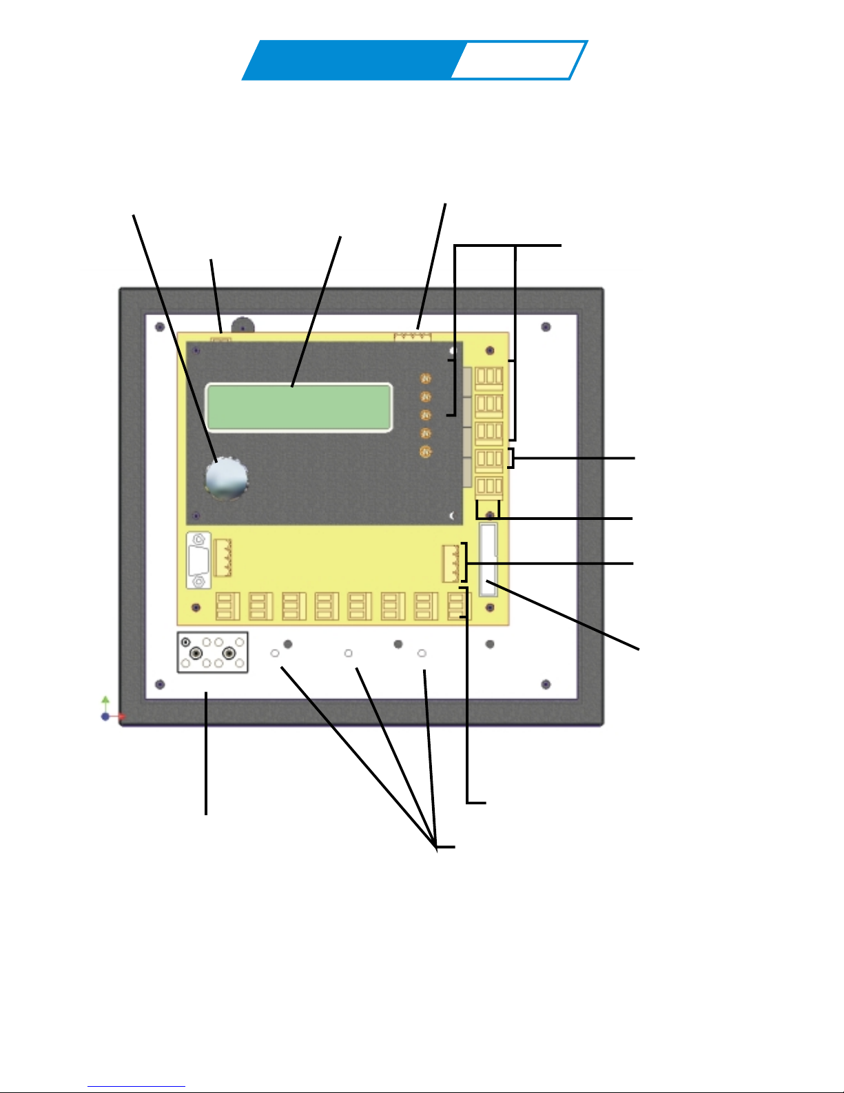
Tocsin 700 Panel Overview
2 x 16 LCD Display
22V DC Panel Power
Digital Inputs
Jog Wheel
3 off Configurable Relay Outputs
With Activation Indication Lamps
Sounder/Flasher
Outputs
Fault Relay Outputs
RS 485 Detector
Data Highway
Connector
(Addressable Versions)
Expansion
Connector
8 off 4-20mA Loop Inputs
Mains/DC Input
(Check Supply Option Before Use)
Grounding Points
L N E 110/230V AC 50/60Hz
OLIVER
IGD
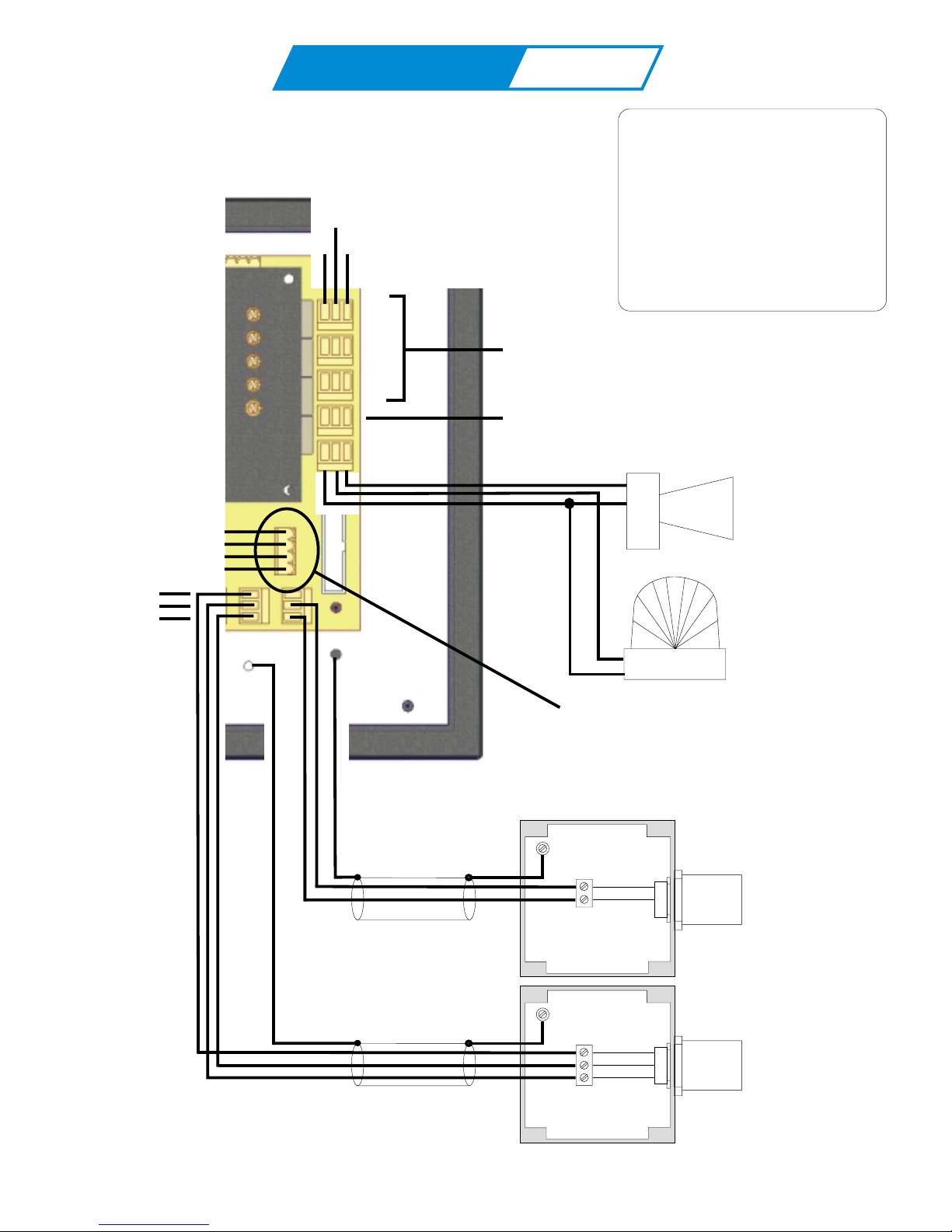
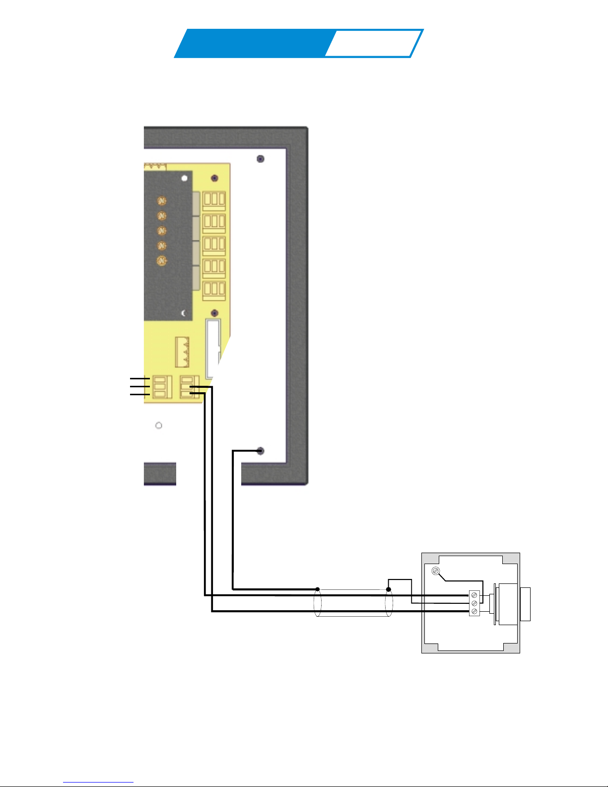
Tocsin 700 Interface wiring
Sounder Alarm
Max Current
150mA 24V DC
These 3 relays can be assigned,
named, zoned etc using the Tocsin
700 operating software.
Dedicated fault relay output, this output
is energised in normal operation
In all Cases:
Relay contact ratings.
7A @ 250V AC Non-Inductive
7A @ 30V DC Non-Inductive
Spike suppression must be fitted
Note that FAULT relays are normally
energised on power up.
Addressable control panel versions only.
See 'Addressable Sensors' Section
24V DC
SOUNDER O/P
WARNING LAMP O/P
Enclosure
Ground
Enclosure
Ground
1.5mmSQ See Panel
for recommended cable
types. Typical max cable
run 500M.
2.5mmSQ See Panel
for recommended cable
types. Typical max cable
run 500M.
Blue
Red
Black
Red
Blue
TOCSIN 102/A
TOXIC GAS
DETECTORS
TOCSIN 102IR
FLAMMABLE GAS/
CO DETECTORS
2
+24V DC
B
A
GND
Note Flasher on
with alarm level 1.
Buzzer on with
alarm level 2.
NO NC
COM
AL1
AL2
AL3
0V DC
4-20mA IN
+24V DC
GND
GND
OLIVER
IGD
OLIVER
IGD
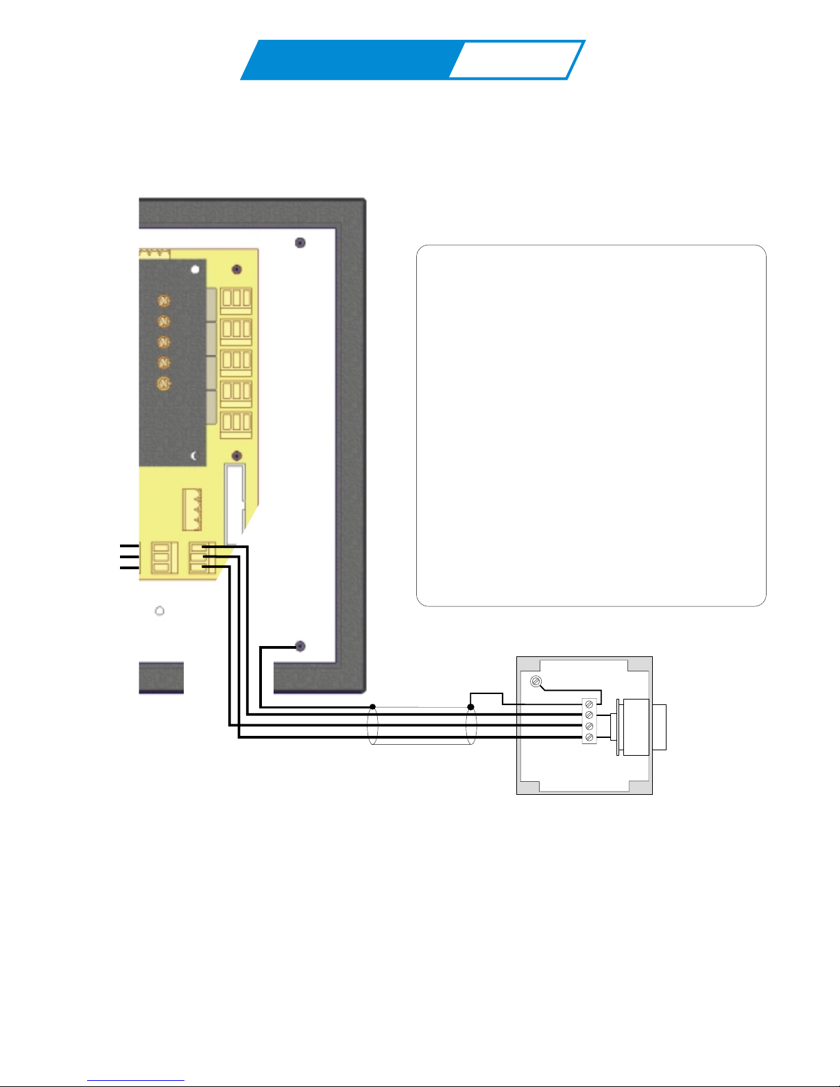
Tocsin 700 Interface wiring...continued
Enclosure
Ground
T103P Pellistor
Flammable Gas
Detectors
1.5mmSQ See Panel
for recommended cable
types. Typical max cable
run 500M.
24V DC
4-20 OUT
0V DC
0V DC
4-20mA IN
+24V DC
GND
0V DC
4-20mA IN
+24V DC
GND
OLIVER
IGD
OLIVER
IGD
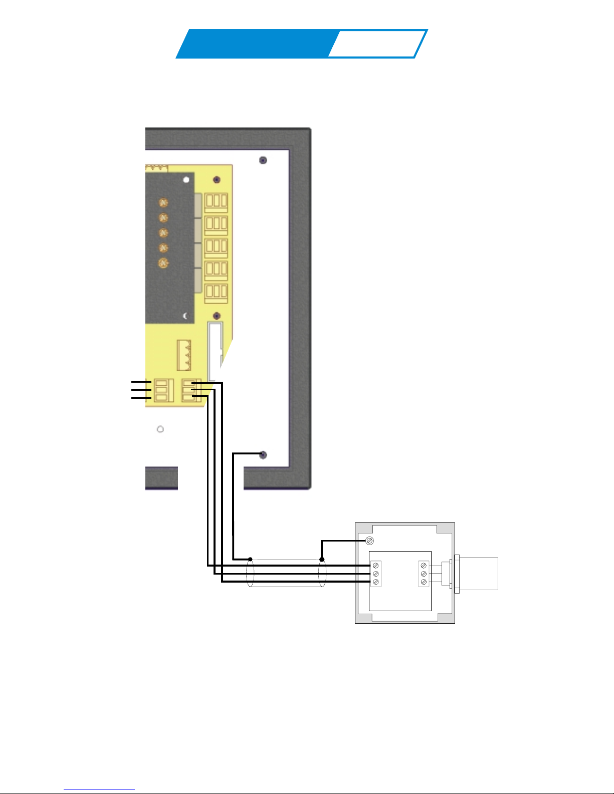
Tocsin 700 Interface wiring...continued
Tocsin 700 to Tocsin 103 2 wire Detector Series
Enclosure
Ground
4-20mA Toxic
And Oxygen Gas
Detectors
1.5mmSQ See Panel
for recommended cable
types. Typical max cable
run 500M.
24V DC
SCREEN
4-20mA
0V DC
4-20mA IN
+24V DC
GND
OLIVER
IGD
OLIVER
IGD
Tocsin 700 Interface wiring...continued
Tocsin 700 to Tocsin 103 3 wire Detector Series
Enclosure
Ground
4-20mA Flammable
And CO Gas
Detectors
2
Cable Guidance Panel
It is imperative to use cabling which suits
the environment in which the T700 and its
sensors are to be used. The following is intended
as a guide.
Fit 1.5mm SQ cable for analogue systems
Fit 2.5mm SQ cable for addressable systems
Use
Pirelli LSX type cable for office/light commercial
un-zoned installations
Steel Wire Armored or CY cable for medium/heavy
industrial un-zoned installations
Mineral Insulated Pyro cable for all hazardous
area zoned installations.
Note in all cases the T700 Panel must be installed outside
of any hazardous area and must be supplied via
a fused spur.
2.5mmSQ See Panel
for recommended cable
types. Typical max cable
run 500M.
Screen
0V DC
24V DC
4-20mA
GND
OLIVER
IGD
OLIVER
IGD
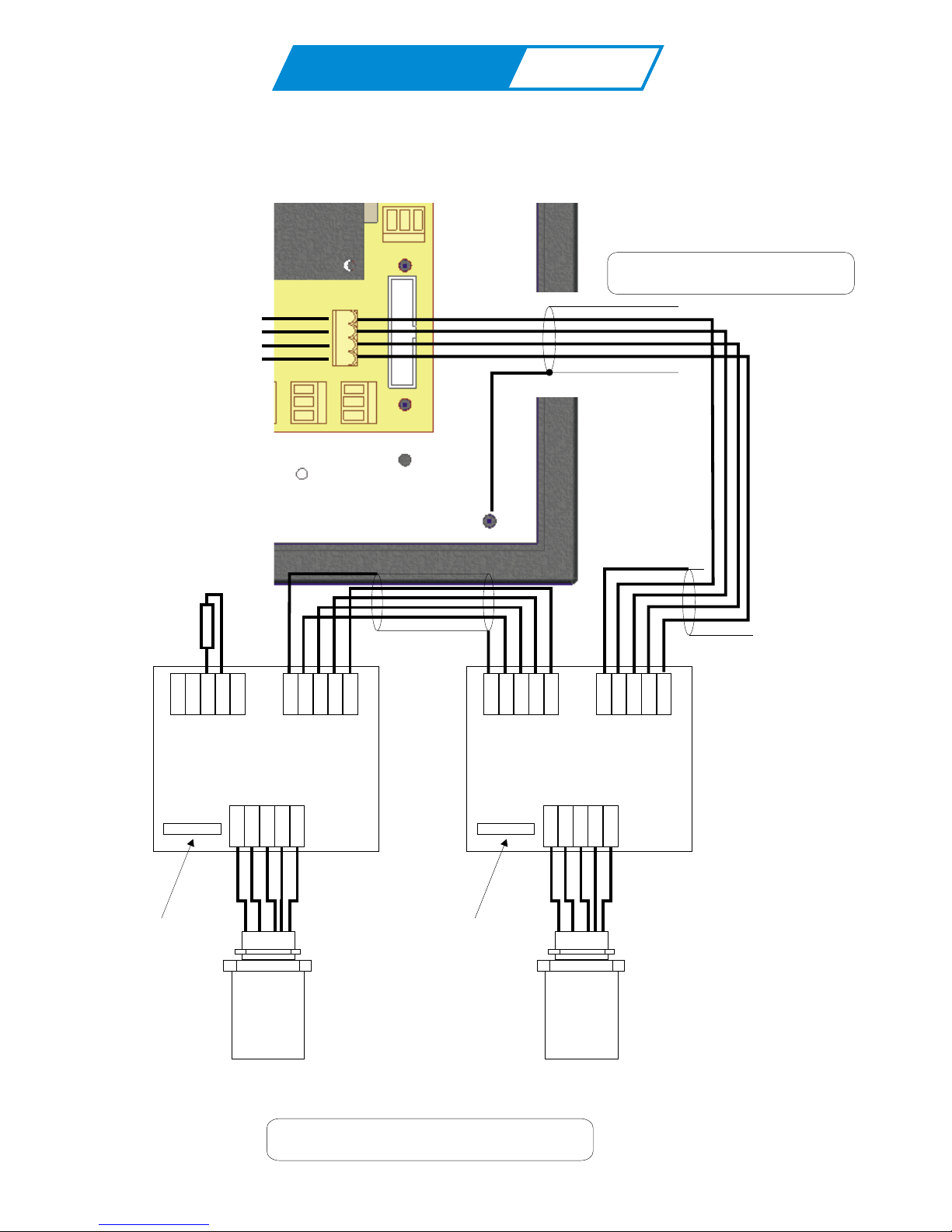
Tocsin 700 Interface wiring...continued, Addressable Systems.
120 Ohm Termination
Resistor on the Last
Detector in Line
2.5mm SQ Cable See Previous Note
Use Junction Boxes Suitable for Area Classification
24V
SCREEN
SCREEN
Rx
24V
24V
Tx
4-20
B
B
A
A
0V
0V
0V
Tocsin 102 Addressable
Series Detector Head
Red
White
Yellow
Blue
Black
Local Comms
Connector For
Palm Connection
24V
SCREEN
SCREEN
Rx
24V
24V
Tx
4-20
B
B
A
A
0V
0V
0V
Tocsin 102 Addressable
Series Detector Head
Red
White
Yellow
Blue
Black
Local Comms
Connector For
Palm Connection
+24V DC
B
A
GND
GND
OLIVER
IGD
OLIVER
IGD
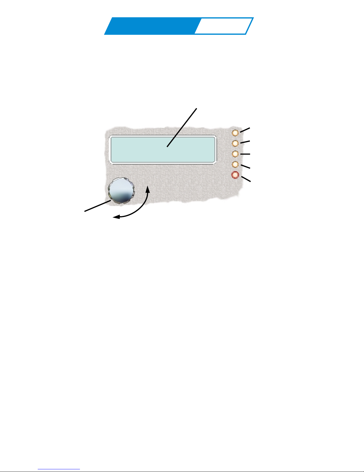
Operating System
Operating System Overview
2 Line x 16 Character LCD Display
Output Relay 1 Lamp
Output Relay 2 Lamp
Output Relay 3 Lamp
System Fault Lamp
Power On
Jog Wheel
Rotate the jog wheel to move
up and down the system
menus.
Press the jog wheel to make
a selection or to accept/silence
an alarm
The Tocsin 700 series gas detector control panels are designed to be as flexible in operation as
possible. The system software allows the owner/installer to configure the following functions:-
Configure input type, not only the selection of pre-programmed input gases but also the option
to define an input type and scale the incoming 4-20mA signal to match. For example,
pressure, temperature, distance etc
Decide alarm levels for each input and decide, rising,falling or latching alarms and which relay
to asign to which inputs to allow, zoning etc
Logical naming of inputs, for example 'boiler room 1'
Set the display scan rate
Zero and calibrate each channel from the control panel.
In addition the Tocsin 700 control panel can be 'hooked up' to a PC or PALM device via its serial
programming link to allow system configuration using Oliver IGD software. This allows not only preconfiguration of the panel prior to commissioning but also a record of how the system was set up.
+Always refer to the shipping manifest and test schedule for confirmation of the shipped
configuration.
 Loading...