

Page 1

Grand Rapids, Michigan, U.S.A. 49504-5298
USER’S OPERATING AND INSTRUCTION MANUAL
MODEL 777-NT
VARIETY SLICER
0777S20000-CV5
Page 2

INDEX
Section Description
Document No. Page No.
SAFETY INSTRUCTIONS ----------------------------------- 0777S20034 -------------- 1-1
DESCRIPTION/SPECIFICATIONS -------------------- -- 0777S20035 ---------------- 2-1
Description -------------------------------------------------------------------------------------- 2-1
Specifications----------------------------------------------------------------------------------- 2-1
INSTALLATION INSTRUCTIONS --------------------- 0777S20036 ---------------- 3-1
Removing the Slicer from the Shipping Platform ------------------------------------- 3-1
Installing the Rubber Feet ------------------------------------------------------------------ 3-2
Installing Optional Casters ----------------------------------------------------------------- 3-2
OPERATING INSTRUCTIONS ---------------------------- 0777S20037 ---------------- 4-1
TROUBLESHOOTING --------------------------------------- 0777S20038 ------------------5-1
The Slicer Will Not Start (Motor is Not Humming) ------------------------------------ 5-1
The Slicer Will Not Start (Motor is Humming) ------------------------------------------ 5-2
The Slicer Starts Without Pulling the Knob --------------------------------------------- 5-2
The Slicer Does Not Stop When Slicing is Complete -------------------------------- 5-2
The Slicer Stops Before Slicing Starts or is Complete ------------------------------- 5-2
Bread Slices Vary in Thickness ----------------------------------------------------------- 5-2
The Blade Frames are Knocking ---------------------------------------------------------- 5-3
MAINTENANCE --------------------------------------------- 0777S20039 ------------------- 6-1
Cleaning ----------------------------------------------------------------------------------------- 6-1
Lubrication -------------------------------------------------------------------------------------- 6-1
Removing the Blade Frames --------------------------------------------------------------- 6-1
Replacing the Blade Frames --------------------------------------------------------------- 6-4
Changing the Blades ------------------------------------------------------------------------- 6-5
Tightening the Belt ---------------------------------------------------------------------------- 6-7
Replacing the Belt ---------------------------------------------------------------------------- 6-8
Adjusting the Blade Frames When Slices Vary in Thickness ---------------------- 6-9
Adjusting the Clearance Between the Blade Frames -------------------------------- 6-9
RECOMMENDED SPARE PARTS -------------------- 0777S20040 -------------- 7-1
REPLACEMENT PARTS SECTION
ASSEMBLY DRAWING (FRAME & BASE) --------- 0777S20041 ---------------- 8-1
REPLACEMENT PARTS (FRAME AND BASE) ----- 0777S20041 ---------------- 8-2
0777S20033 0-1
Page 3

INDEX
(Continued)
Section Description Document No. Page No.
REPLACEMENT PARTS SECTION (CONTINUED
ASSEMBLY DRAWING (HOLDDOWN & PUSHER) -- 0777S20042 ----- 9-1
REPLACEMENT PARTS (HOLDDOWN & PUSHER) -- 0777S20042 ----- 9-2
ASSEMBLY DRAWING (ROCKER & PULLEY) --------- 0777S20043 ---- 10-1
REPLACEMENT PARTS (ROCKER & PULLEY) -----------0777S20043 ------ 10-2
ASSEMBLY DRAWING (BLADE FRAME) ----------------- 0777S20044 ----- 11-1
REPLACEMENT PARTS (BLADE FRAME) ------------------0777S20044 ---- 11-2
ELECTRICAL SINGLE PHASE ------------------------ 0777S20045 ------- 12-1
Wiring Diagram (Single Phase) ---------------------------------------------------------- 12-1
Assembly Drawing (Single Phase) ------------------------------------------------------ 12-1
Parts List 1/2 HP, 115 VAC, 60 Hertz, 1 Phase -------------------------------------- 12-2
Parts List 1/2 HP, 230 VAC, 60 Hertz, 1 Phase -------------------------------------- 12-2
Parts List 1/2 HP, 220 VAC, 50 Hertz, 1 Phase -------------------------------------- 12-2
ELECTRICAL THREE PHASE ------------------------ 0777S20046 -------- 13-1
Wiring Diagram (Single Phase) ---------------------------------------------------------- 13-1
Assembly Drawing (Single Phase) ------------------------------------------------------ 13-1
WARRANTY ----------------------------------------------------------------------------- GEN 040225
WARRANTY PROCEDURE --------------------------------------------------------- GEN 040226
RETURNED PARTS POLICY ------------------------------------------------------- GEN 040227
0777S20033 0-2
Page 4

SAFETY INSTRUCTIONS
WARNING
VARIOUS SAFETY DEVICES AND METHODS OF GUARDING HAVE BEEN
PROVIDED ON THIS MACHINE. IT IS ESSENTIAL HOWEVER THAT THE MACHINE
OPERATORS AND MAINTENANCE PERSONNEL OBSERVE THE FOLLOWING
SAFETY PRECAUTIONS. IMPROPER INSTALLATION, MAINTENANCE, OR
OPERATION OF THIS EQUIPMENT COULD CAUSE SERIOUS INJURY OR DEATH.
1. Read this manual before attempting to operate your machine. Never allow an
untrained person to operate or service this machine.
2. Connect the machine to a properly grounded electrical supply that matches the
requirements shown on the electrical specification plate and follow all specifications
of local electrical codes.
3. Disconnect and lock-out the machine from the power supply before cleaning or
servicing.
4. Check and secure all guards before starting the machine.
5. Observe all caution and warning labels affixed to the machine.
6. Use only proper replacement parts.
7. Do not wear loose fitting clothing or loose hair when working near this machine.
Shirt tails should be tucked in.
8. Wear proper, personal, protective, safety equipment.
9. Keep Hands away form the moving parts of this machine while it is in operation.
10. In addition to these general safety instructions, also follow the more specific safety
instructions given for the different areas of the machine operating instruction manual.
WARNING
DO NOT USE FOR OTHER THAN ORIGINALLY INTENDED PURPOSE.
0777S20034 1-1
Page 5
DESCRIPTION/SPECIFICATIONS
Description
The Oliver Variety Slicer is a compact, sturdy, time tested design, which has been used
in bakeries world wide for many years. It is easy to operate and allows the slicing of
virtually all varieties of bread, quickly and cleanly, with a spring fed pusher that gently
moves the product through the knives followed by a automatic shut off. Its design will
provide years of efficient, trouble-free operation requiring a minimum of maintenance.
The Variety Slicer is of stainless steel, plated, and painted construction for easy cleaning
and maintenance. The knives can be replaced, by most operators, without the need of a
service call.
The Variety Slicer is backed by Oliver Products Company, who has a reputation of
serving the Baking Industry for well over 60 years.
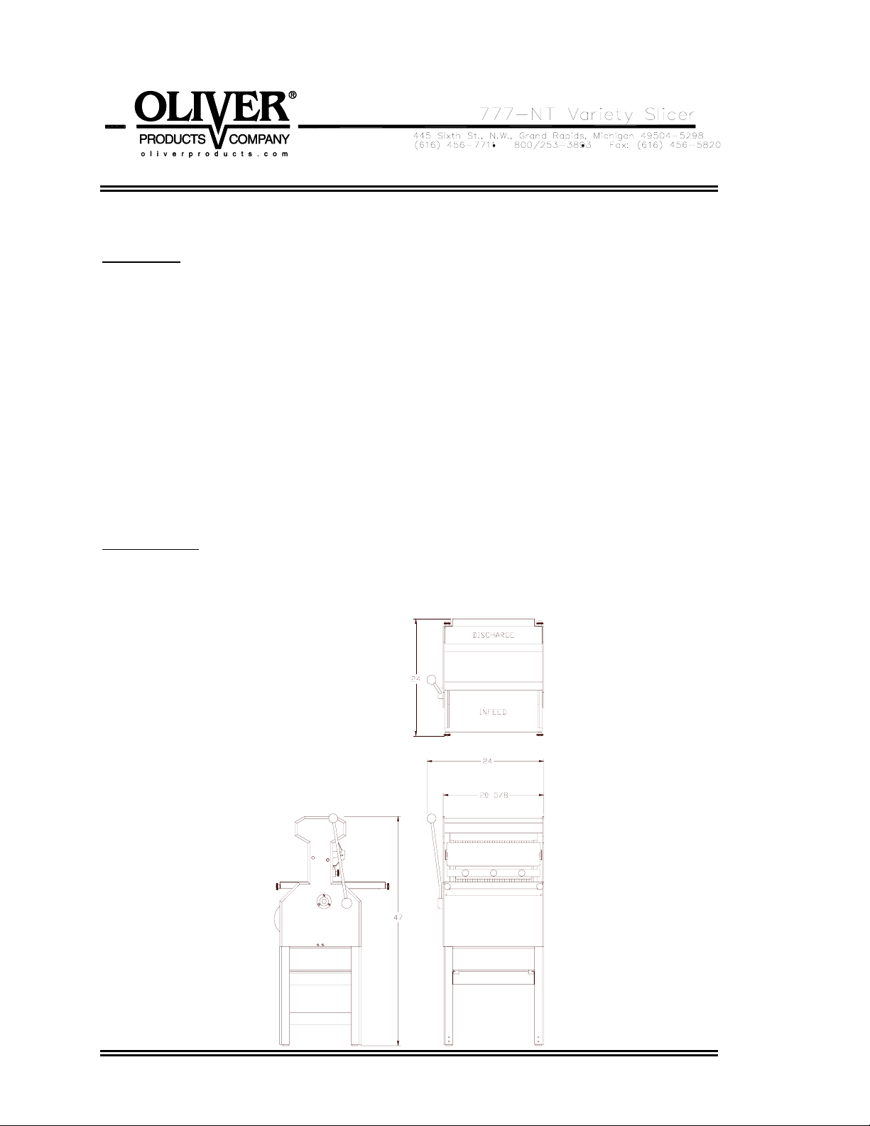
Specifications
Space Requirements: (All Dimensions are Approximate)
0777S20035 2-1
Page 6

Product Capacities:
Up to 16” long, 10-1/2” wide and from 3-1/2 to 6” high.
Electrical Options Available:
1 phase, 60 hz, 115VAC, 7 Amps.
1 phase, 60 hz, 230VAC, 3.5 Amps.
Others Available consult factory.
Standard Slice Spacings
7/16, 1/2, 9/16
Optional Slice Spacings (At additional cost)
1/4, 5/16, 3/8, 5/8, 3/4, 7/8, 1”
Others Available consult factory.
Shipping Weight
250 lbs. (Floor Model)
0777S20035 2-2
Page 7
INSTALLATION INSTRUCTIONS
CAUTION
THE SLICER IS HEAVY, USE PROPER TECHNIQUE WHEN LIFTING.
KEEP BACK STRAIGHT, KNEES BENT, AND LIFT WITH LEGS.
USE GLOVES TO PROTECT HANDS.
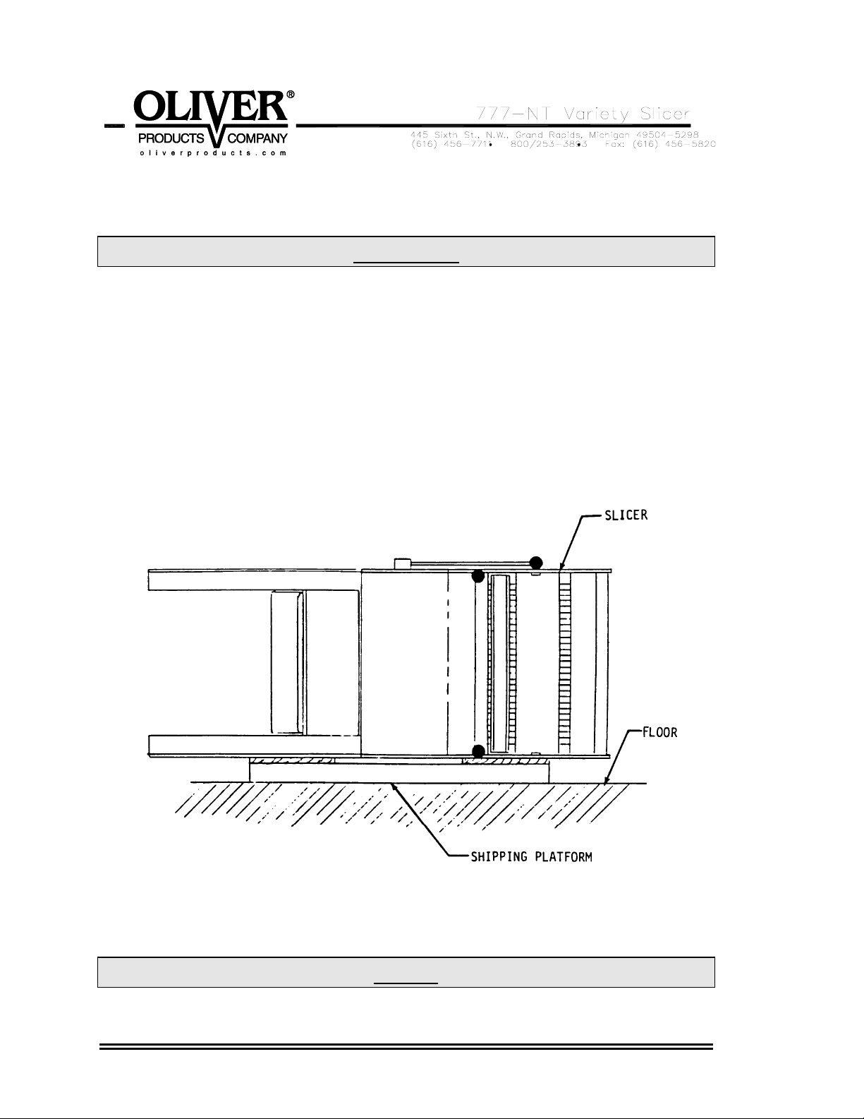
Removing the Slicer from the Shipping Platform
Lift the slicer off the shipping platform with one person on each side of the slicer. Set the
slicer down on a level floor.
Using the shipping platform or other blocks, carefully lower the slicer to its side as shown
below.
NOTE
PERFORM THE FOLLOWING DEPENDING ON WHICH OPTIONS
0777S20036 3-1
Page 8
HAVE BEEN ORDERED WITH THE MACHINE.
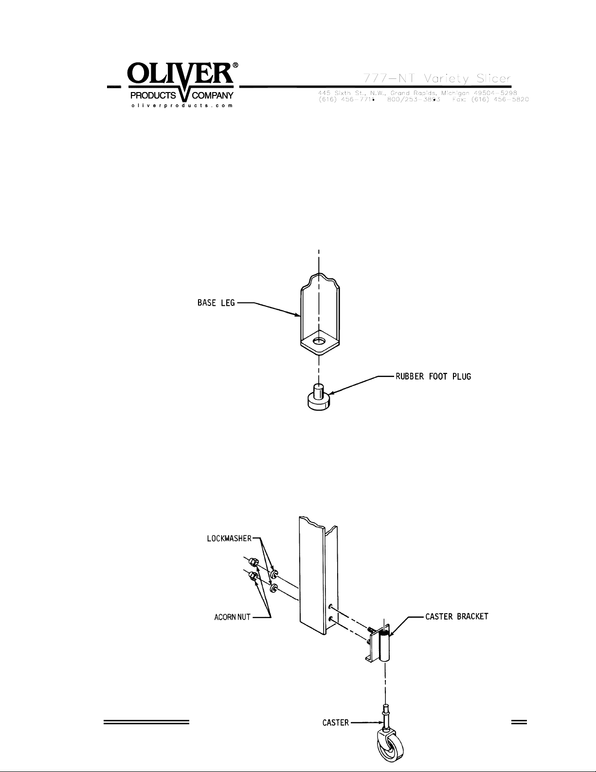
Installing the Rubber Feet
Remove the rubber feet from the accessory package and insert the plugs into the
holes in the leg bottoms, see below. Carefully restore the machine to the upright
position.
Installing Optional Casters
Remove the casters, caster brackets and hardware from the accessory package.
Insert the studs of the brackets, see figure below, through the holes provided on
the base of the slicer. Secure the brackets with the lock washers and hex acorn
nuts. Press fit the casters into the brackets as shown below. Carefully restore
the machine to the upright position.
0777S20036 3-2
Page 9

0777S20036 3-3
Page 10
OPERATING INSTRUCTIONS
CAUTION
ALWAYS USE CARE WHENEVER WORKING NEAR THE CUTTING KNIVES.
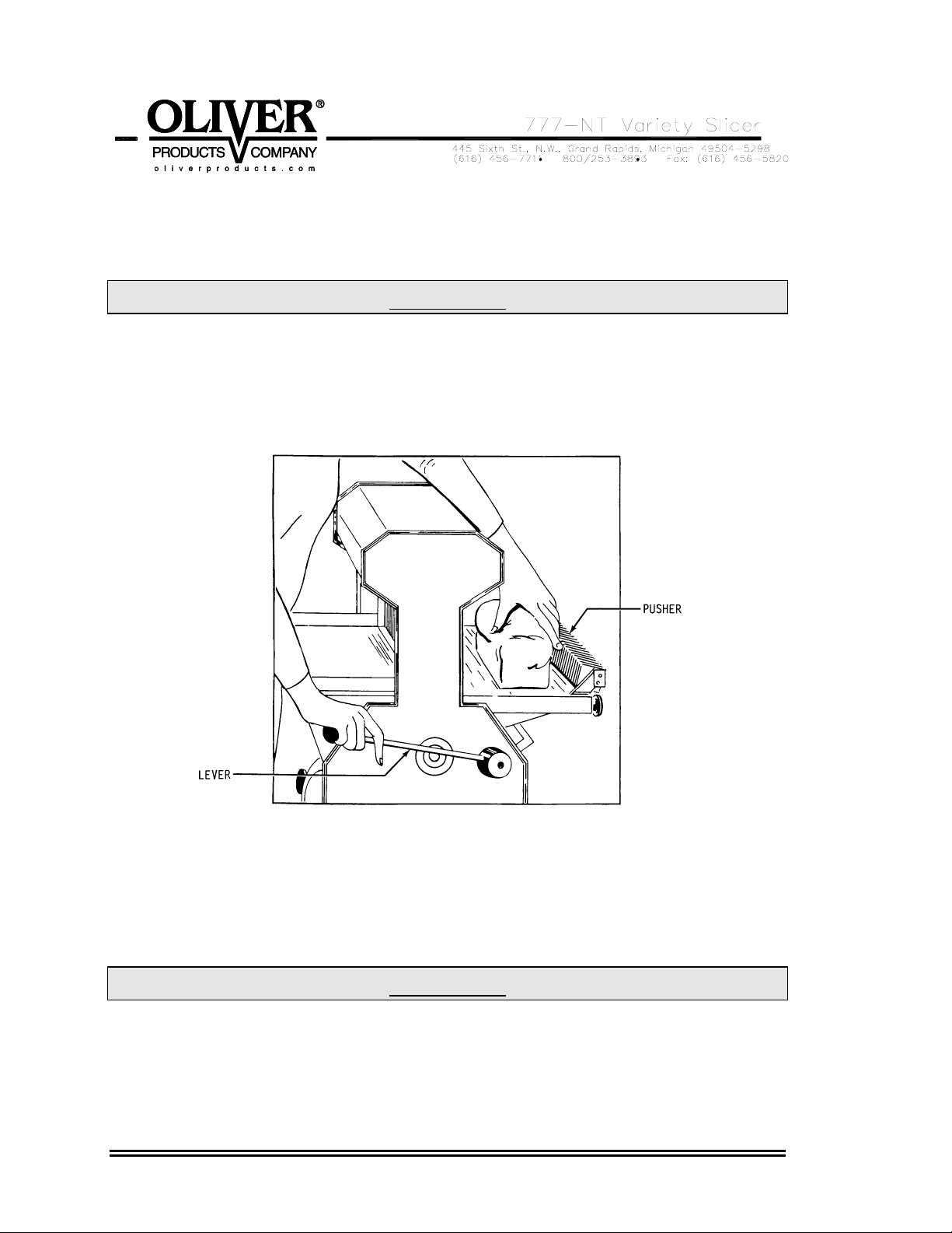
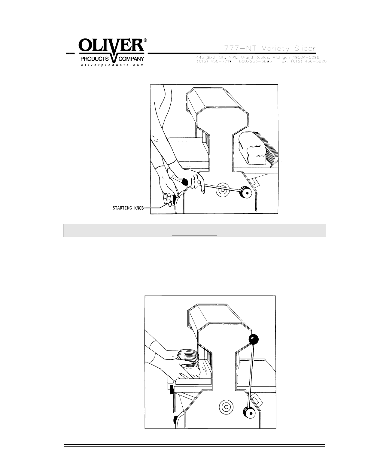
To operate the slicer, stand on the discharge side, grasp the lever with the right hand,
see below, pull it down as far as it will go and hold it there. With the left hand place the
loaf of bread in front of the pusher.
While continuing to hold the lever down with the right hand move the left hand to the
discharge side of the machine and pull the motor starting knob, see next illustration.
Allow the right hand to raise slowly with the lever until the loaf contacts the slicer blades.
After the knives have pierced the crust remove your right hand from the lever allowing
the pusher to move the loaf through the knives.
CAUTION
NEVER PUSH THE HAND LEVER.
DOING SO MAY RESULT IN DAMAGE TO THE MACHINE’S COMPONENTS.
0777S20037 4-1
Page 11
CAUTION
THE KNIVES ARE EXTREMELY SHARP.
DO NOT TOUCH MOVING OR STATIONARY KNIVES.
The motor and slicer knives will stop automatically when the pusher comes to its full
forward position. Remove the loaf from the table and bag or wrap the product. Use the
same procedure for each loaf.
0777S20037 4-2
Page 12
TROUBLESHOOTING
WARNING
ALWAYS DISCONNECT THE SLICER FROM THE POWER SUPPLY BEFORE
ATTEMPTING ANY TYPE OF MAINTENANCE TASK, INCLUDING
TROUBLESHOOTING.
The Slicer Will Not Start (Motor Is Not Humming)
• The machine is not plugged in.
• There is no power at the outlet. (Check by plugging in a small working appliance,
like a lamp. Check to see if a circuit breaker has tripped. If the circuit breaker has
not tripped and the circuit is still not working have a qualified electrician check the
circuit.)
• The motor switch overload has tripped. (To reset push firmly in the direction shown
on the switch nameplate.)
• There are bread crumbs in the motor starting switch. (Have a qualified electrician
disassemble the switch and clean it.)
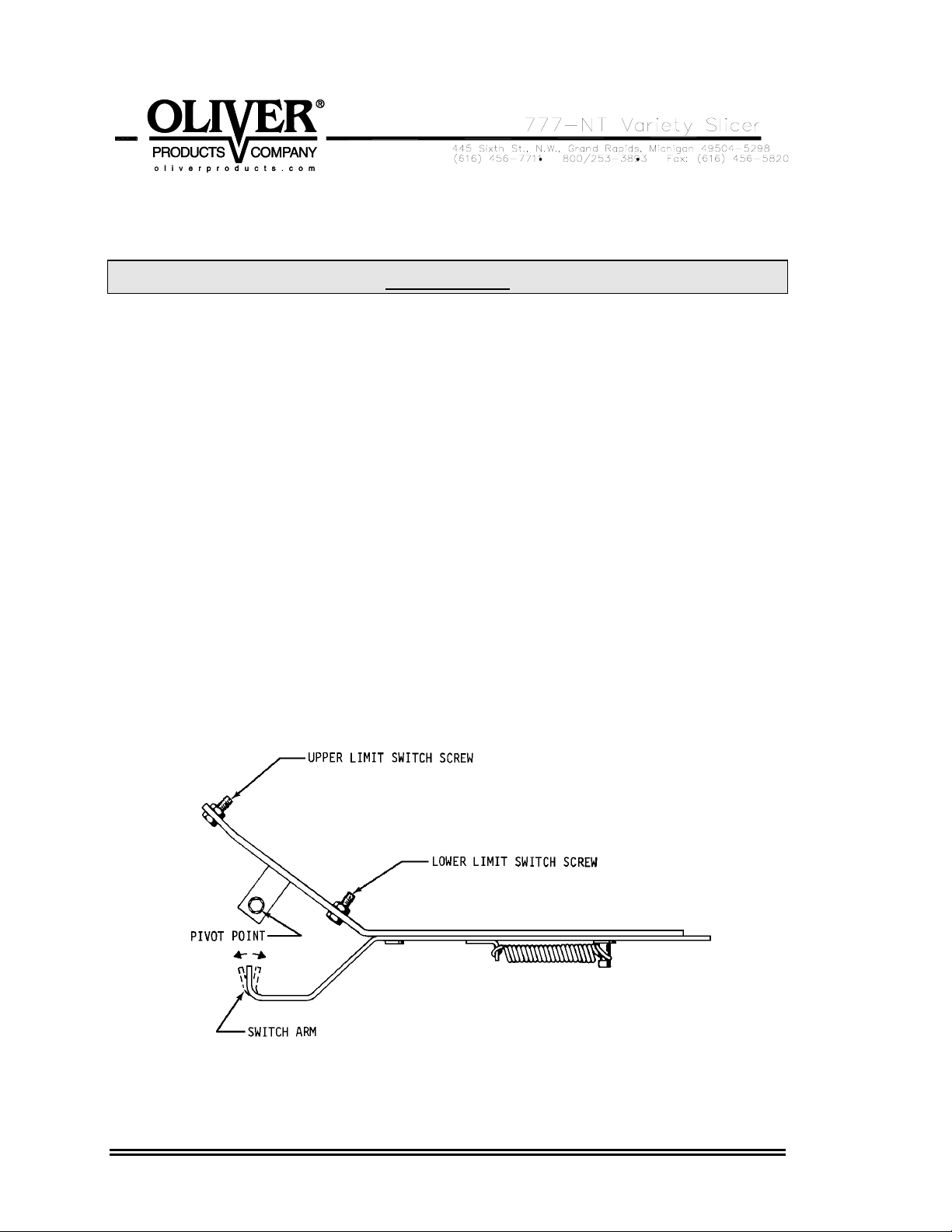
• The switch arm on the Switch Trip Mechanism is bent. (A qualified service agent can
bend the arm to correct the problem, see the illustration below.)
• The switch trip mechanism is binding. (Clean the mechanism and lubricate its pivot
point, see above illustration.)
0777S20038 5-1
Page 13

• The upper limit switch is not being made. (Adjust the limit switch screws as required
to correct the problem, see above illustration.)
The Slicer Will Not Start (Motor Is Humming)
CAUTION
DO NOT ALLOW THE MOTOR TO HUM WITHOUT STARTING.
THE MOTOR CAN BE PERMANENTLY DAMAGED BY OVERHEATING.
• The motor has failed. (Have it checked by a qualified electrician.)
NOTE
A SPECIAL NON-VENTILATED MOTOR MUST BE USED WITH THIS SLICER.
• The drive system is binding. (Have a qualified service agent check for defective
bearings or other restrictions to free movement.)
• There is mechanical interference between other parts of the slicer. (Have a qualified
service agent evaluate the machine for adjustment or replacement of defective
parts.)
The Slicer Starts Without Pulling the Knob
• The switch arm on the Switch Trip Mechanism is bent. (A qualified service agent can
bend the arm to correct the problem, see the illustration in the “The Slicer Will Not
Start” section above.)
The Slicer Does Not Stop When Slicing is Complete
• Either one or both of the upper and lower limit switch screws on the limit switch trip
mechanism are out of adjustment. (Adjust the limit switch screws as required to
correct the problem, see the illustration in the “The Slicer Will Not Start”, section
above.)
The Slicer Stops Before Slicing Starts or is Complete
• The lower limit switch screw on the limit switch trip mechanism is out of adjustment.
(Adjust the screw as required to correct the problem, see the illustration in the “The
Slicer Will Not Start”, section above.)
• The switch trip mechanism is binding. (Clean the mechanism and lubricate its pivot
point, see the illustration in the “The Slicer Will Not Start”, section above.)
0777S20038 5-2
Page 14

Bread Slices Vary in Thickness
• The blade frames are out of adjustment. (See the “Maintenance” section of this
manual under “Adjusting the Blade Frames When Slices Vary in Thickness” on how
to perform this adjustment.)
The Blade Frames Are Knocking
• The blade frames are out of adjustment. (See the “Maintenance” section of this
manual under “Adjusting the Clearance Between the Blade Frames” on how to
perform this adjustment.)
0777S20038 5-3
Page 15
MAINTENANCE
WARNING
ALWAYS DISCONNECT THE SLICER FROM THE POWER SUPPLY BEFORE
ATTEMPTING ANY TYPE OF MAINTENANCE TASK.
Cleaning
Use a mild detergent solution to clean all exterior surfaces and empty the crumb tray
daily or more often if necessary. Periodically remove both tables and the crumb chute
and then brush, blow, (if compressed air is available), or wipe all foreign material from all
surfaces, especially from moving parts.
Lubrication
Once a month, more often during heavy use, put a drop of food approved lubricant on
each of the pivot points of the plastic links at the top to the blade frames. Also add a
drop or two of the same food approved lubricant to the switch trip mechanism pivot point,
pusher lever and yoke pivots. All other bearings are either grease packed or sealed and
seldom need attention.
NOTE
NEVER OIL OR GREASE THE MOTOR.
Removing the Blade Frames
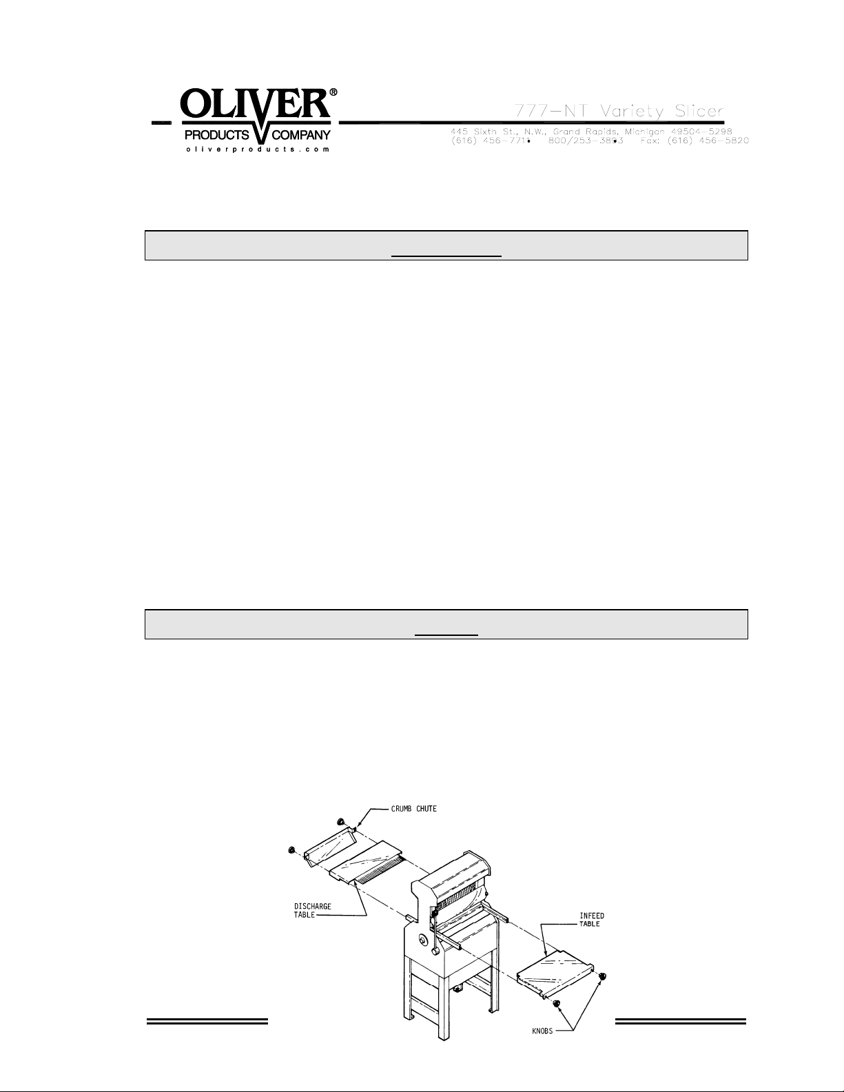
To remove the blade frames you must first remove the infeed table, crumb chute, and
discharge table. First remove the four black knobs securing the tables, (see the
illustration below). In addition to the knobs the infeed and discharge tables are held in
place by friction so pull the infeed table straight out and hard to separate them.
0777S20039 6-1
Page 16

Removing the Blade Frames (Continued)
Always start by removing the discharge side blade frame first. Both blade frames should
be removed from the discharge side of the machine. You should remove the discharge
side blade frame completely from the machine before starting on the infeed side blade
frame. However each is removed using similar procedures.
NOTE
NEVER LOOSEN THE NUTS ON THE ECCENTRIC PINS OR ATTEMPT
TO REMOVE THEM TO AID IN REMOVING THE BLADE FRAMES.
Start by pulling the hairpin clip from the eccentric pin, located at the top of each blade
frame, see illustration below, then slide the top link toward the lever side of the slicer.
Make sure that the link is forced all the way over to the cross member.
Next remove the two locking cams, eye bolts, with belleville washers, from the bottom of
the blade frame, they secure the frame to the rocker’s swing shaft. The eye bolts can be
removed by turning them counter clockwise once the cams have been removed. See
the next illustration.
0777S20039 6-2
Page 17

CAUTION
THE BLADES ARE EXTREMELY SHARP.
ALWAYS HANDLE BLADE FRAMES WITH CARE.
The blade frame can now be carefully lifted from the slicer. See below. The remaining
blade frame can be removed in the same manner.
0777S20039 6-3
Page 18

Replacing the Blade Frames
Replacement of the blade frames is done by reversing the removal procedures. Ensure
That the feet of the blade frames rest snuggly on the swing shafts and that you have
included the belleville washers with the eye bolts.
NOTE
WHEN INSTALLING THE BELLEVILLE WASHERS, THEY MUST BE
SO THAT THE CROWN IS UP AS SHOWN IN THE ILLUSTRATION BELOW.
0777S20039 6-4
PLACED
Page 19

When replacing the eye bolts turn them clockwise until moderate pressure is required to
close the cam. If the cam is to easy to close rotate the eye bolt a half turn more in the
clockwise direction and try to reinstall the cam. Repeat these partial rotations until
moderate pressure is required to close the cam. If the cams are either difficult or
impossible to close, rotate the eye bolt a half turn in the counter clockwise direction.
Repeat until the cams can be closed using moderate pressure.
Changing the Blades
CAUTION
THE BLADES ARE EXTREMELY SHARP. ALWAYS HANDLE THEM WITH CARE.
NOTE
DO NOT INTERCHANGE THE TWO BLADE FRAMES. REPLACE THE BLADE
FRAME TO THE SAME SIDE OF THE MACHINE AS IT WAS TAKEN FROM
0777S20039 6-5
Page 20

NOTE
WHEN CHAINGING BLADES FIRST NOTE THE DIRECTION THE SHARPENED
EDGES ARE FACING ON THE BLADE FRAME. THEY ARE FACING UP ON ONE
FRAME AND DOWN ON THE OTHER. DO NOT CHANGE THIS DIRECTION.
Place the blade frame on a flat surface. You may use the special knife tool, shown in
the illustration below, or use a common set of pliers to depress the spring-loaded pin
holding each knife. This will reduce the tension on the knife so that it may be easily
removed.
In the illustration below you can see the use of the knife tool. It is inserted into the blade
frame on the spring-loaded pin end and then by lifting up on the tool it will deflect the
upper spring-loaded pin reducing the tension on the knife. Once this has been done the
knife can be carefully removed.
Rev. 2/15/05
Changing the Blades (Continued)
The new knife can be installed by reversing the removal procedure. A paper clip can be
used to hold the knife in position on the lower pin to ease installation. See the illustration
below.
NOTE
0777S20039 6-6
Page 21

WHEN REPLACING ALL THE KNIVES, ALWAYS REMOVE THE CENTER KNIVES
FIRST AND WORK TOWARD THE ENDS. INSTALL THE NEW KNIVES AT THE
ENDS FIRST AND WORK ALTERNATELY TOWARD THE CENTER.
CAUTION
NEVER
PUT BLADE FRAMES IN THE SLICER WITHOUT KNIVES.
Tightening the Belt
CAUTION
OVER-TIGHTENING THE DRIVE BELT
MAY CAUSE BEARING OR MOTOR FAILURE.
0777S20039 6-7
Page 22

Remove the crumb tray from the slicer. Locate the adjustment nut at the lower end of
the motor mounting plate, see below. Turn the adjustment nut clockwise with a wrench
to increase tension on the drive belt. To reduce tension, turn the adjusting nut
counterclockwise. The drive belt should be just tight enough, using moderate finger
pressure, to allow a 3/8 inch deflection halfway between the motor drive pulley and the
driven pulley.
Replacing the Belt
Remove the infeed table, crumb chute, and discharge table. First remove the four black
knobs securing the tables, (see the illustration below). In addition to the knobs the
0777S20039 6-8
Page 23

infeed and discharge tables are held in place by friction so pull the infeed table straight
out and hard to separate them.
Turn the adjustment nut, at the lower end of the motor mounting plate, counterclockwise
with a wrench to loosen the drive belt, see “Tightening the Belt” above.
Disconnect the end of the connecting rod at the rocker by removing the two cap screws
and cap as shown below. The drive belt may now be removed from the pulleys
The new belt can be installed by reversing the removal procedure. Refer to the
“Tightening the Belt” section to adjust the tension on the drive belt.
Adjusting the Blade Frames When Slices Vary in Thickness
0777S20039 6-9
Page 24

Remove the discharge table from the slicer. Loosen, but, do not remove the two locking
cams which secure the blade frame to the swing shaft. Remove the plastic plug over the
set screw in the fixed collar, see below. Using an allen wrench, loosen, do not remove
the set screw in the fixed collar. Using a ruler, (15” maximum), measure the distance
between the blades. Gently tap the collar with a small mallet either to the right or left
until the distances between the blades are equal. When satisfied with the location
tighten the fixed collar’s set screw and replace the plastic plug. Lastly tighten the two
locking cams which secure the blade frame.
Adjusting the Clearance Between the Blade Frames
The distance between the blade frames is adjusted by rotating the eccentric pins located
above the blade frames. Two wrenches are used to do this. One wrench is used to
keep the eccentric pin from rotating while the second is used to loosen the lock nut on
the end of the pin. This nut secures the pin in position once its proper location is
determined. See the illustration below.
0777S20039 6-10
Page 25

To adjust the eccentric, once the lock nut is loosened, rotate the pin using the wrench
used to hold the pin. Rotate the pin, (it is possible that both pins will need adjustment at
the same time), until the knives of the machine are in line within a 1/32 of an inch,
(alternating blades should not appear be in front of or behind each other when viewed
from the side). It is easiest to view this alignment my placing a straight edge horizontally
along the blades midway between the ends of the blade on the blade’s dull side,
(discharge side), when the blade frames are inline or level. When the eccentric pins are
in the desired position tighten each of the lock nuts to secure the position of the
eccentrics. Check the blade frame clearance by turning the driven pulley by hand.
0777S20039 6-11
Page 26

RECOMMENDED SPARE PARTS
PART NUMBER
PART DESCRIPTION NO. REQ’D
5835-7705 Clip-Haripin 2
0730-0031 Pin-Eccentric 2
0797-0059-2 Pin- STST Metric Blade Frame 2
0711-0002 Link-Top 2
5601-1119* Belt-V 4L290 (60 Cycle Machines) 1
5709-1137* Switch-Starter (1 Phase Machines) 1
5220-5001 Bearing-Driven Pulley (With Snap Ring) 1
5220-5040 Bearing-Driven Pulley 1
0797-0058-019 Stud-Driven Pulley 1
6904-6001 Gasket-Driven Pulley 1
0797-0071-3 Rod-Connecting 1
0797-0057-219 Stud-Swing 1
5220-4040 Bearing-Rocker Shaft 2
5220-0042 Bearing-Swing Shaft 4
6301-3609* Motor-1/2 HP, 1-60-115/230 1
5757-8140 Switch-Limit 1
*For Other Electrics Contact the Factory
0777S20040 7-1
Page 27

0777S20041 8-1
Page 28

MECHANICAL REPLACEMENT PARTS LIST
EXPLODED VIEW (FRAME & BASE)
ITEM NO PART DESCRIPTION PART NUMBER QUANITY
101 NEW STYLE FRAME 0777-0001-3 1
107 BUSHING 0777-0063 1
130 BAGGING SCOOP-TOP MTG 0797-2048-002 1
131 SCREW-HEX HD ¼-20 X ¾ STST 5843-1003 2
132 WASHER-LOCK ¼” STST SPRIN 5851-9357 2
133 WASHER- ¼” FLAT 18-8 STST 5851-9304 2
151 TRIMLESS BASE 0777-0950-002 1
152 SLIDE – DRAWER 0777-0948 2
156 TRAY-EX CAP CRUMB 0777-0949 1
157 HOLDER-FRAME WITH STUD (NSF) 0777-0046-101 2
158 NUT-ACCORN 3/8-16 NC STST 5832-0587 2
159 SCREW – RDHD SL STST ¼-20X 5/8 5843-5255 4
160 WASHER-FLAT 3/8” 18-8 STST 5851-9306 2
161 WASHER-LOCK 5/16” STST 18-8 5851-9358 4
162 BUMPER-#242ATLANTIC INDIA RBBR 5902-0001 4
\
410 HUB-PUSHER 0777-0121-1 1
413 LEVER-PUSHER 0711-0024 1
415 KNOB-BALL 1-7/8” DIA 3/8-24BR INS 5911-7002 1
565 KNOB-KNRLD ¼-20 TAP 1-3/8 DIA 5911-7000 4
For Service Parts Call Oliver Products @ 800-253-3893
0777S20041 8-2
Page 29

MECHANICAL REPLACEMENT PARTS LIST
EXPLODED VIEW (FRAME & BASE
(CONTINUED)
ITEM NO PART DESCRIPTION PART NUMBER QUANITY
567 PLATE-SWITCH 0777-0898-001 1
568 SCREW FLAT HD 10-24 X 3/8 STST 5843-5067 2
569 CHUTE 0777-0073-1 1
571 TABLE – INFEED 0777-0074-001 1
601* TABLE 0777-0024-0XX 1
801 BRACKET-CASTER MTG 0777-0947-001 4
802 NUT – ACCORN ¼-20NC STST 5832-0590 8
803 WASHER LOCK ¼” STST SPRING 5851-9357 8
804 CASTER-SWIVEL 2-1/2” DIA (NSF) 5902-2347 2
805 CASTER-SWIVEL 2-1/2” W/BRK. (NSF) 5902-2348 2
* Specify Slice Thickness
For Service Parts Call Oliver Products @ 800-253-3893
0777S20041 8-3
Page 30

MECHANICAL REPLACEMENT PARTS LIST
EXPLODED VIEW
(HOLDDOWN & PUSHER)
0777S20041 9-1
Page 31

MECHANICAL REPLACEMENT PARTS LIST
EXPLODED VIEW
(HOLDDOWN & PUSHER)
ITEM NO PART DESCRIPTION PART NUMBER QUANITY
105 HAIRPIN CLIP 3/8” GROOVE DIA. 5835-7705 5
107 BUSHING 0777-0063 1
108 BUSHING 0777-0071 1
114 GROMMET-5/16ID X 3/4MD ATIND#167 5767-1200 2
115 NUT-ACCORN 5/16-18 NC STST 5832-0584 4
116 SCREW-FLAT HD 5/16-18 X 1” STST 5843-5099 2
117 WASHER-LOCK 5/16” STST 18-8 5851-9358 2
351 FRAME-HOLDDOWN 0777-0975 1
352 BUSHING 0777-0065 2
353 BUSHING 0777-0066 2
354 SCREW-PIVOT 0777-0068-001 2
356 WASHER-LOCK 5/16” STST 18-8 5851-9358 2
357 STUD-HOLDDOWN PIVOT 0777-0067-001 2
401 YOKE-SWING (PWDR COATED WHITE) 0777-0078-001 1
402 PIN-YOKE 0777-0033-001 1
404 RING-RETAINING TRUARC#5100-50H 5840-2837 1
405 LINK-PUSHER (STST) 0777-0912-001 1
407 LINK-PUSHER (STST) 0777-013-001 1
408 CLIP-STST 0777-0085-001 2
For Service Parts Call Oliver Products @ 800-253-3893
0777S20041 9-2
Page 32

MECHANICAL REPLACEMENT PARTS LIST
EXPLODED VIEW
(HOLDDOWN & PUSHER)
(CONTINUED)
ITEM NO PART DESCRIPTION PART NUMBER QUANITY
410 HUB-PUSHER 0777-0121-1 1
411 SCREW-HEX HD 3/8-24X1-1/2 STST 5843-1306 1
412 WASHER-3/8 STST MD SPRNG LOCK 5851-9359 1
413 LEVER-PUSHER 0711-0024 1
414 SCREW-SOCSET CUPPT 3 /8 X 3/8 NC 5842-6158 1
415 KNOB-BALL 1-7/8”DIA 3/8-24BR INS 5911-7002 1
416 ARM-PUSHER RH (PLATED) 0777-0077-0011 1
417 ARM-PUSHER LH (PLATED) 0777-0077-0012 1
418 BLOCK-777 SLIDE PER PRINT 5500-2800 2
420 ARM-FRONT CHROME PLATED 0777-0082-002 1
421 ARM-REAR CHROME PLATED 0777-0083-002 1
422 WASHER-DELRIN SPACER 0777-0920 2
424 SPRING-STD. 25/32x4-1/8 PRINT 4605-1000-0031 2
551 ARM-SWITCH OPERATOR (PLATED) 0777-0119-101 1
552 SPRING-STD. 9/16x2 13/16 PRINT 4605-1000-003 1
553 BEARING-SINT BRNZ SLV 5254-0167 1
554 NUT-HEX FULL 5/16-18NC FIN STST 5832-0521 2
555 SCREW-HEX HD ¼-20 X 5/8 STST 5843-1002 1
556 SCREW-HEX HD 5/16-18 X ¾ 5842-1528 2
For Service Parts Call Oliver Products @ 800-253-3893
0777S20041 9-3
Page 33

MECHANICAL REPLACEMENT PARTS LIST
EXPLODED VIEW
(HOLDDOWN & PUSHER)
(CONTINUED)
ITEM NO PART DESCRIPTION PART NUMBER QUANITY
557 WASHER-1/4” FLAT 18-8 STST 5851-9304 1
558 STOP-ARM 0777-0120-001 1
559 STUD-STOP 0777-0973 1
560 STUD-KNOB 0777-0974 1
561 WASHER-HORSESHOE 0793-0084 2
562 SPRING-STD. 11/32x1-7/16 PRINT 4605-1000-0032 1
563 SPRING-STD. 31/64x1-3/8 PRINT 4605-1000-0033 1
564 NUT-HX FULL ¼-20NC STST FIN. 5832-0520 1
565 BUSHING-RUBBR1/4x5/8x5/8#1069 5902-0100 4
602* HOLDDOWN-GUIDE- SLICE SIZE 0777-0976-0XX 1
605* PUSHER ASS’Y (SLICE SIZE) 0777-0978-0XX 1
607 BAR-PUSHER (777-N) 0777-0979 1
608 ROLLER 0777-0982 1
609 AXLE 0777-0983 1
610 NUT-ACCORN 3/16 {10-24} STST 5832-0585 4
611 SCREW FLAT HD 10-24 X 3/8 STST 5843-5067 1
612 SCREW-SLTD TRSHD MACH 10x1/2SS 5843-5385 4
613 WASHER-#10 STST INTRNL TTH LOCK 5851-9394 4
*SPECIFY SLICE THICKNESS
For Service Parts Call Oliver Products @ 800-253-3893
0777S20041 9-4
Page 34

MECHANICAL REPLACEMENT PARTS LIST
EXPLODED VIEW
(ROCKER & PULLEY)
0777S20041 10-1
Page 35

MECHANICAL REPLACEMENT PARTS LIST
EXPLODED VIEW
(ROCKER & PULLEY)
ITEM NO PART DESCRIPTION PART NUMBER QUANITY
101 NEW STYLE FRAME (NT) 0777-0001-3 1
118 BEARING-BALL 20x47x14 2 SEALS 5220-4040 2
119 CAP BALL BEARING 4090-0233-0023 2
120 GASKET-CORK (PER PRINT) 6904-6000 2
121 CAP-PWDR COAT WHITE 4090-0233-0044 1
122 SCREW-RDHD SL STST ¼-20x5/8 5843-5255 6
124 CAP 4090-0244-0005 1
128 SCREW-RDHD SL STST ¼-20x1/4 5843-5251 4
129 GASKET-CORK (PER PRINT) 6904-6001 1
134 CAP-CLAMP 0730-0023 1
135 WASHER-STST SPRING LOCK M10 8851-9468 2
136 SCREW-STST HEX HD M10 X 40MM 8843-0331 2
301 ROCKER (METRIC) 0777-0047-3 1
302 SCREW-HEX HD M6 X 16MM DIN 933 8842-0544 2
303 WASHER-STST FLAT M25.4 8851-8495 2
304 WASHER-SPRING LOCK M6 DIN 127B 8851-9414 2
305 SHAFT-SWING 0730-0024-001 2
306 COLLAR-HOLD DOWN 0797-0031-002 2
307 COLLAR-LOCATING 0797-0031-003 2
For Service Parts Call Oliver Products @ 800-253-3893
0777S20041 10-2
Page 36

MECHANICAL REPLACEMENT PARTS LIST
EXPLODED VIEW
(ROCKER & PULLEY)
(CONTINUED)
ITEM NO PART DESCRIPTION PART NUMBER QUANITY
308 ROD-THREADED 3/8-16 UNC NYLON 5840-8076 2
309 SCREW-SOCSET CUPPT 3/8x1/4 NC 5842-6156 2
310 BEARING-BALL-W/SNP RNG 10MMBR 5220-0042 4
311 NUT-STST HEX HD JAM M10 X 1.5 8832-0418 4
451 PULLEY-DRIVEN PLATED 0730-0005-001 1
452 STUD, STST 0797-0058-019 1
453 STUD-SWING 0797-0057-219 1
454 ROD-CONNECTING (MOLDED) 0797-0071-3 1
455 RING-SNAP (EXTERNAL) 5840-2825 2
456 BEARING-MET BALL SKF #6205-2RS 5220-5040 2
457 RING-RETAINING TRUARC#N5000-200 5840-1040 2
458 SCREW-HEX HD M10 X 20MM DIN933 8842-0583 1
459 WASHER-FLAT M10 DIN 9021 8851-8418 1
460 WASHER-SPRING LOCK M10 DIN127B 8851-9418 1
For Service Parts Call Oliver Products @ 800-253-3893
0777S20041 10-3
Page 37

MECHANICAL REPLACEMENT PARTS LIST
EXPLODED VIEW
(BLADE FRAME)
0777S20041 11-1
Page 38

MECHANICAL REPLACEMENT PARTS LIST
EXPLODED VIEW
(BLADE FRAME)
ITEM NO PART DESCRIPTION PART NUMBER QUANITY
106 WASHER-STST SPRING LOCK M10 8851-9468 4
306 COLLAR-HOLD DOWN 0797-0031-002 2
307 COLLAR-LOCATING 0797-0031-003 2
312 BOLT-EYE 0777-0970 4
313 CAM 0777-0971 4
314 WASHER-7/8 STST BELLEVILLE SPRI 5852-0050 4
565 KNOB-KNRLD1/4-20TAP 1-3/8”DIA. 5911-7000 4
569 CHUTE 0777-0073-1 1
571 TABLE – INFEED 0777-0074-001 1
601* TABLE 0777-0024-0XX 1
603* BLADE FRAME 0797-0300-0XX 2
604 BLADE-TYPE A 0797-0029-1 *
614 PIN-STST METRIC BLADE FRAME 0797-0059-2 2
*SPECIFY SLICE THICKNESS
For Service Parts Call Oliver Products @ 800-253-3893
0777S20041 11-2
Page 39

ELECTRICAL SINGLE PHASE
Wiring Diagram (Single Phase)
Assembly Drawing (Single Phase Electrics)
0777S20045 12-1
Page 40

Parts List 1/2 HP, 115 VAC, 60 Hertz, 1 Phase
ITEM NO PART DESCRIPTION PART NUMBE
901 Motor-1/2 HP 6301-3609
910 Pulley-Motor 4575-7103-2001
913 Belt-V 4L290 5601-1119
914 Switch-Starter 5709-1137
915 Heater-Overload 5708-2430
917 Cover-Switch 0797-2131
918 Boot-Switch 5757-4515
919 Cord-Power W/Plug 0777-1040
922 Switch-Limit 5757-8140
925 Conduit-Switch 0777-0989
926 Fitting-90 Deg. Elbow 5766-7760
927 Fitting-Straight ½” 5766-7758
Parts List 1/2 HP, 230 VAC, 60 Hertz, 1 Phase
ITEM NO PART DESCRIPTION PART NUMBE
901 Motor-1/2 HP 6301-3609
910 Pulley-Motor 4575-7103-2001
913 Belt-V 4L290 5601-1119
914 Switch-Starter 5709-1137
915 Heater-Overload 5708-2423
917 Cover-Switch 0797-2131
918 Boot-Switch 5757-4515
919 Cord-Power W/Plug 0777-1078
922 Switch-Limit 5757-8140
925 Conduit-Switch 0777-0989
926 Fitting-90 Deg. Elbow 5766-7760
927 Fitting-Straight ½” 5766-7758
Parts List 1/2 HP, 220 VAC, 50 Hertz, 1 Phase
ITEM NO PART DESCRIPTION PART NUMBE
901 Motor-1/2 HP 6301-3940
910 Pulley-Motor 4575-7104-2004
913 Belt-V 4L290 5601-1120
914 Switch-Starter 5709-1137
915 Heater-Overload 5708-2425
917 Cover-Switch 0797-2131
918 Boot-Switch 5757-4515
919 Cord-Power W/Plug 0777-0980
922 Switch-Limit 5757-8140
925 Conduit-Switch 0777-0989
926 Fitting-90 Deg. Elbow 5766-7760
927 Fitting-Straight ½” 5766-7758
REV. 9-2-0
For Parts and Service call (800)-253-3893
0777S20045 12-2
Page 41

ELECTRICAL THREE PHASE
Wiring Diagram (Three Phase)
Assembly Drawing (Three Phase Electrics)
0777S20043 13-1
Page 42

Parts List 1/2 HP, 230 VAC, 60 Hertz, 3 Phase
ITEM NO PART DESCRIPTION PART NUMBER
901 Motor-1/2 HP 6301-3800
910 Pulley-Motor 4575-7103-2003
913 Belt-V 4L290 5601-1119
914 Switch-Starter Magnetic 5709-8823
915 Heater-Overload 5708-2173
919 Cord-Power
922 Switch-Limit 5757-8140
925 Fitting-Offset Nipple
926 Fitting-90 Deg. Elbow
927 Fitting-Straight
928 Switch-Manual 5757-9325
0777S20043 13-2
Page 43

Parts List 1/2 HP, 460 VAC, 60 Hertz, 3 Phase
ITEM NO PART DESCRIPTION PART NUMBER
901 Motor-1/2 HP 6301-3800
910 Pulley-Motor 4575-7103-2003
913 Belt-V 4L290 5601-1119
914 Switch-Starter Magnetic 5709-8827
915 Heater-Overload 5708-2166
919 Cord-Power
922 Switch-Limit 5757-8140
925 Fitting-Offset Nipple
926 Fitting-90 Deg. Elbow
927 Fitting-Straight
928 Switch-Manual 5757-9325
For Service Parts Call Oliver Products @ 800-253-3893
0777S20043 13-3
Page 44

THIS PAGE WAS INTENTIONALLY
LEFT BLANK.
GEN020319
Page 45

WARRANTY
PARTS
Oliver Products Company (Oliver) warrants that if any part of the equipment (other than a part not
manufactured by Oliver) proves to be defective (as defined below) within one year after shipment,
and if Buyer returns the defective part to Oliver within one year, Freight Prepaid to Oliver’s plant in
Grand Rapids, MI, then Oliver, shall, at Oliver’s option, either repair or replace the defective part, at
Oliver’s expense.
LABOR
Oliver further warrants that equipment properly installed in accordance with our special instructions,
which proves to be defective in material or workmanship under normal use within one (1) year from
installation or one (1) year and three (3) months from actual shipment date, whichever date comes
first, will be repaired by Oliver or an Oliver Authorized Service Dealer, in accordance with Oliver’s
published Service Schedule.
For purposes of this warranty, a defective part or defective equipment is a part or equipment which is
found by Oliver to have been defective in materials workmanship, if the defect materially impairs the
value of the equipment to Buyer. Oliver has no obligation as to parts or components not
manufactured by Oliver, but Oliver assigns to Buyer any warranties made to Oliver by the
manufacturer thereof.
This warranty does not apply to:
1. Damage caused by shipping or accident.
2. Damage resulting from improper installation or alteration.
3. Equipment misused, abused, altered, not maintained on a regular basis, operated carelessly, or
used in abnormal conditions.
4. Equipment used in conjunction with products of other manufacturers unless such use is approved
by Oliver Products in writing.
5. Periodic maintenance of equipment, including but not limited to lubrication, replacement of wear
items, and other adjustments required due to installation, set up, or normal wear.
6. Losses or damage resulting from malfunction.
The foregoing warranty is in lieu of all other warranties expressed or implied AND OLIVER MAKES
NO WARRANTY OF MERCHANTABILITY OR FITNESS FOR PURPOSE REGARDING THE
EQUIPMENT COVERED BY THIS WARRANTY. Oliver neither assumes nor authorizes any person
to assume for it any other obligations or liability in connection with said equipment. OLIVER SHALL
NOT BE LIABLE FOR LOSS OF TIME, INCONVENIENCE, COMMERCIAL LOSS, INCIDENTAL OR
CONSEQUENTIAL DAMAGES.
GEN 040225
Page 46

THIS PAGE WAS INTENTIONALLY
LEFT BLANK.
GEN020319
Page 47

WARRANTY PROCEDURE
1. If a problem should occur, either the dealer or the end user must contact the Customer
Service Department and explain the problem.
2. The Customer Service Manager will determine if the warranty will apply to this particular
problem.
3. If the Customer Service Manager approves, a Work Authorization Number will be
generated, and the appropriate service agency will perform the service.
4. The service dealer will then complete an invoice and send it to the Customer Service
Department at Oliver Products Company.
5. The Customer Service Manager of Oliver Products Company will review the invoice and
returned parts, if applicable, and approve for payment.
GEN 040226
Page 48

THIS PAGE WAS INTENTIONALLY
LEFT BLANK.
GEN020319
Page 49

RETURNED PARTS POLICY
This policy applies to all parts returned to the factory whether for warranted credit,
replacement, repair or re-stocking.
Oliver Products Company requires that the customer obtain a Return Material Authorization
(RMA) number before returning any part. This number should appear on the shipping label
and inside the shipping carton as well. All parts are to be returned prepaid. Following this
procedure will insure prompt handling of all returned parts.
To obtain an RMA number contact the Repair Parts Deptartment toll free at (800) 253-3893.
Parts returned for re-stocking are subject to a RE-STOCKING CHARGE.
Thank you for your cooperation,
Repair Parts Manager
Oliver Products Company
GEN 040227
 Loading...