

Pro OUT (v.1.2) ASSEMBLY MANUAL
MAIN PCB
Open the main board bag
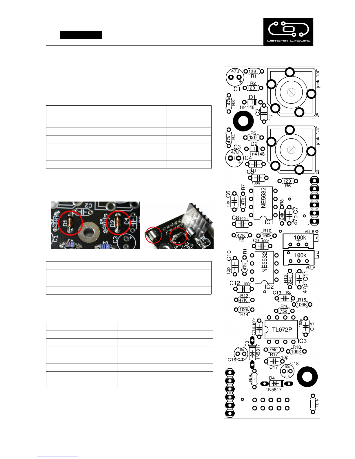
1) Solder the resistors according to the suggested value in the drawing.
You can identify its value with the colour code or with a multimeter.
QTY VALUE CODE NAME
6 47k Yellow, violet, black, red, brown R9, R3, R4, R7, R11,
R13
4 100k Brown, black, black, orange, brown R15, R18, R10, R14
4 120 Brown, black, black, black, brown R1, R2, R5, R6
2 24k Red, yellow, black, red, brown R8, R12
2 75K Violet, green, black, red,brown R16,R17
2) Now with the diodes, observe the correct polarity, and the ferrites
using a cut leg of the diodes D3 and D4.
QTY VALUE NAME
2 1N4148 D1, D2 (polarized)
2 1N5817 D3, D4 (polarized)
2 FER+ FERr-
3) Now with the capacitors.
QTY VALUE CODE NAME
6 100n 104 C5, C8, C9, C12, C14, C15
4 10p 100 C6, C10, C13, C17
2 1uF 105 C2, C4
2 47p 470 C7,C11
2 47uF 47uf C1, C3 (polarized)
2 10uF 10uF C16, C18 (polarized)
4) Now the sockets, observe the orientation, 5) Solder the female pins and the connector power
6) Solder the 100k trimmers in VU_A and VU_B
7) Place the ICs in its sockets, observe the orientation.
IC1 and IC2: NE5532
CONTROL PCB
Open the control board bag
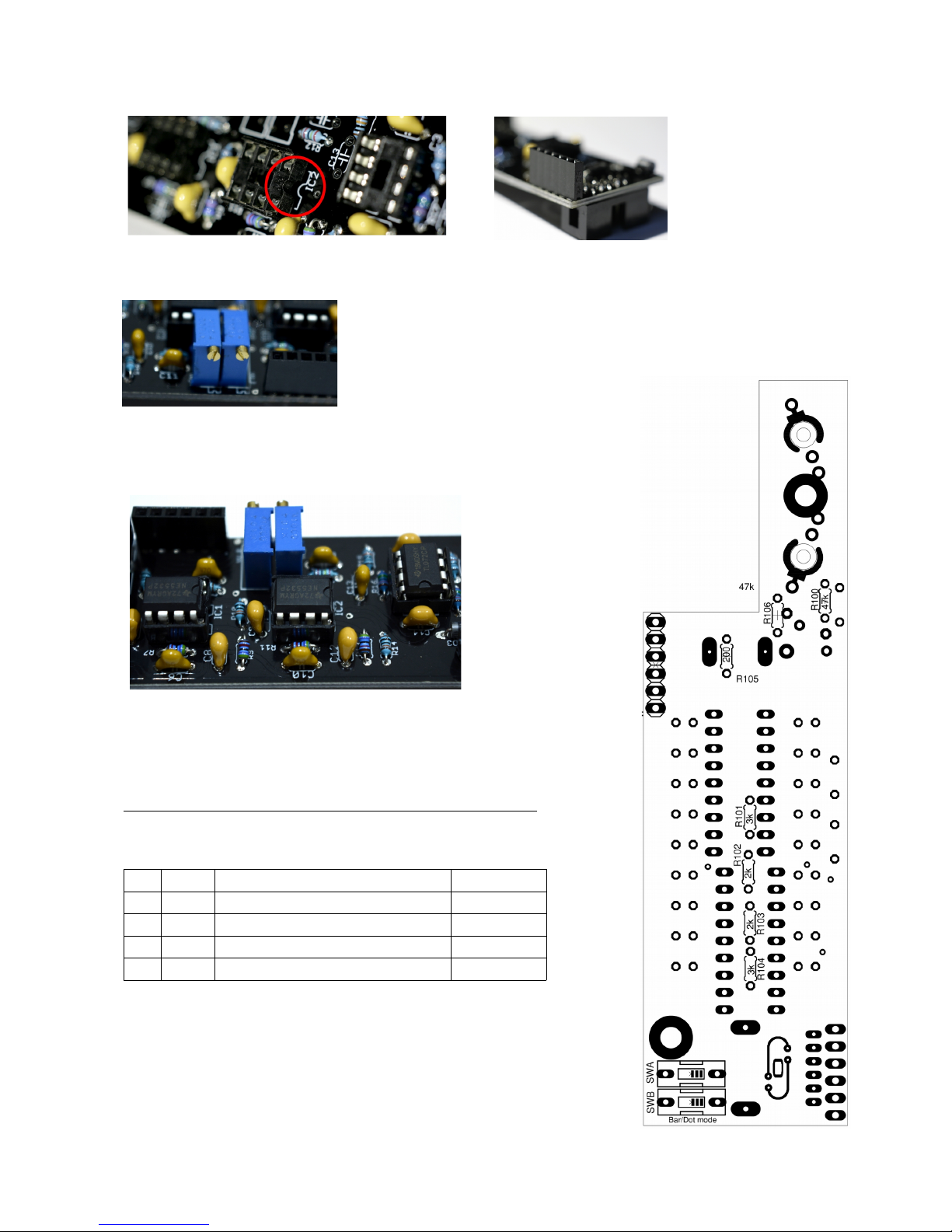
1) First solder the following resistors
QTY VALUE CODE NAME
2 200 Red, black, black, black, brown R105, R107
2 2k Red, black, black,brown,brown R102, R103
2 3k Orange, black, black, brown, brown R101, R104
2 47k Yellow, violet, black, red, brown R100, R106
2) Solder the micro switchs
-------------------------------------------------->

3) Now, in the upper part of the PCB, you have to solder the sockets.( IC100 and IC 101)
And place ICs lm3915
4) Solder the capacitors.
QTY VALUE CODE NAME
2 47u 47u C101, C102
2 10n 103 C103, C104
5) Screw the spacers and solder the male pins, as you can see in the picture..
6) Without soldering, place the jacks, the potentiometer and the leds, long leg (+) to
the left. Solder the gnd of the jack st_out,

7) Put a little of insulating tape, or something like that, in the panel, as you can see in the picture.
8) Place the panel, screw jacks and potentiometer in the right position, and then solder them.
9) Place leds in its corresponding holes, as you can see in the picture. Now, solder the leds and afterwards,
remove the insulating tape.
10) Place the 6.3 mm jacks in the PCB main without soldering and connect the PCB main with the PCB control.
Screw the 6.3 mm jacks and solder them.
LISTO!
CALIBRATION
1. Place a 10Vpp signal (for example, an oscillator) in the input A.
2. Adjust the volume knob at maximum level
3. Now, adjust the A and B trimmers until the Vumeters indicate +6dB.
For a sharper adjust, place the 10Vpp signal and measure with an oscilloscope in the balanced outs (+4dBu),
move the volume potentiometer until you get a 3.47Vpp signal. Adjust the A and B trimmers until the Vumeter
indicates 0dB.
All right! Thank you very much and enjoy it!
If you have any question or doubt: contact@olitronik.com
manual with color photos and more info at olitronik.com
 Loading...