

Page 1
PROTO-SHIELD development board
Users Manual
All boards produced by Olimex are ROHS compliant
Revision Initial, June 2011
Copyright(c) 2011, OLIMEX Ltd, All rights reserved
Page 1
Page 2

INTRODUCTION:
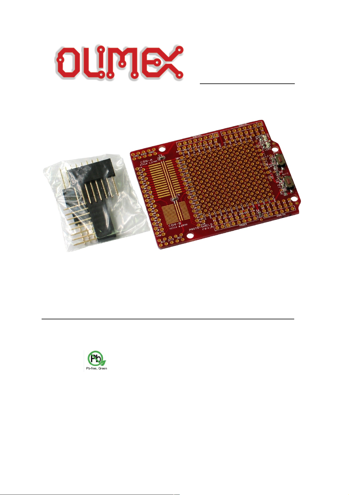
PROTO-SHIELD is prototype board compatible with all of Olimex's AR-
DUINO compatible boards – like OLIMEXINO-328, OLIMEXINO-STM32 and
PIC32-PINGUINO. The board comes without mounted connectors on it, but it is
shipped with one 6x1 connector and three 8x1 connectors, which can be mounted
by the customer. The prototype area gives user the opportunity to solder different
extensions for ARDUINO compatible boards. All this allows you to build a diversity of applications.
BOARD FEATURES:
• one 6x1 connector – not mounted
• three 8x1 connectors – not mounted
• two status leds
• two user buttons
• prototype area
• FR-4, 1.5 mm, soldermask, component print
• Dimensions: 68.58 x 53.34mm (2.71 x 2.11")
ELECTROSTATIC WARNING:
The PROTO-SHIELD board is shipped in protective anti-static packaging. The
board must not be subject to high electrostatic potentials. General practice for
working with static sensitive devices should be applied when working with this
board.
BOARD USE REQUIREMENTS:
Hardware: The board can be used with any of our ARDUINO compatible
boards: OLIMEXINO-328, OLIMEXINO-STM32, PIC32-PINGUINO, PIC32-
PINGUINO-OTG.
Page 2
Page 3
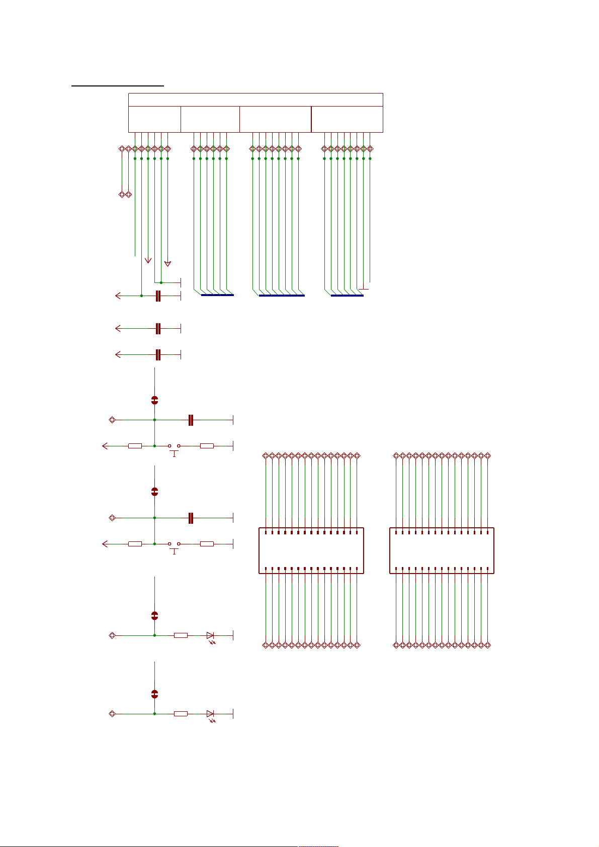
SCHEMATIC:
Page 3
T1107A(6x3.8x2.5mm)
T1107A(6x3.8x2.5mm)
100nF
2.2uF/16V
10 0n F
10 0n F
100nF
PRO TOSHI ELD_ 1. 27 MM
PRO TOSHI ELD_ 0. 65 MM
RED GREEN
VIN
3V3
3V3
3V3
+5V
3V33V3
4.7k4.7k
33 0R 33 0R
33 0R
33 0R
A0A1A2A3A4( SD A)
A5(SC L)
A6
A7
ARE F
BUT1
BUT1
BUT 2
BUT2
C201
C202
C2 03
C2 04
C2 05
C2 06
C2 07
C2 08
C2 09
C210
C211
C212
C213
C214
C2 15 C2 16
C217
C218
C219
C220
C221
C2 22
C2 23
C2 24
C2 25
C2 26
C2 27
C2 28
C229
C230
C301
C3 02
C3 03
C3 04
C3 05
C3 06
C3 07
C3 08
C3 09
C310
C311
C312
C313
C3 14
C3 15 C3 16
C3 17
C318
C319
C320
C321
C3 22
C3 23
C3 24
C3 25
C3 26
C3 27
C3 28
C3 29
C330
D0 (R XD)
D1 (TX D)
D2
D5
D8
D9(L ED2)
D10( #SS)
D11( MO SI)
D12( MISO )
D1 3( SC K/L ED 1)
GN D
LED1
LED1
LED 2
LED 2
RES ET
+5V
1A1B2A2B3A
3B
3V3
4A4B5A5B6A6B7A7B8A8B9A9B10 A
10 B
11 A
11 B
12 A
12 B
13 A
13 B
14 A
14 B
15 A
15 B
16 A
16 B
17 A
17 B
18 A
18 B
19 A
19 B
20 A
20 B
21 A
21 B
22 A
22 B
23 A
23 B
24 A
24 B
25 A
25 B
26 A
26 B
27 A
27 B
28 A
28 B
29 A
29 B
30 A
30 B
A0A1A2A3A4
A5
A6
A7
ARE F
B1
12
B1_E
B2
12
B2_E
BUT1 BUT2
C1
C2
C3
C4
C5
1122334455667788991010111112121313141415
15
1616171718181919202021212222232324242525262627272828292930
30
CO N- A
1122334455667788991010111112121313141415
15
1616171718181919202021212222232324242525262627272828292930
30
CO N- B
D0
D1
D2D3D4D5D6
D7
D8
D9
D10
D11
D12
D1 3
GN D_ 1
GN D_ 2
GN D_ 3
L1
12
L1 _E
L2
12
L2 _E
LED1 LED2
P3
P6
R1R2
R3 R4
R5
R6
RES ET
3V3
5V
A0A1A2A3A4
A5
AREF
D0D1D2D3D4D5D6
D7
D8D9D10
D11
D12
D13
GND
GND
GND
RST
VIN
VIN
PROTO-SHIELD
Re v.A
CO PYR IG HT(C) 2 011 , O LIMEX L td.
htt p: //w ww .olime x.c om/dev
POW ER ANALOG DIGITAL DIGITAL
ARDUINO: SH PLATFORM
Page 4
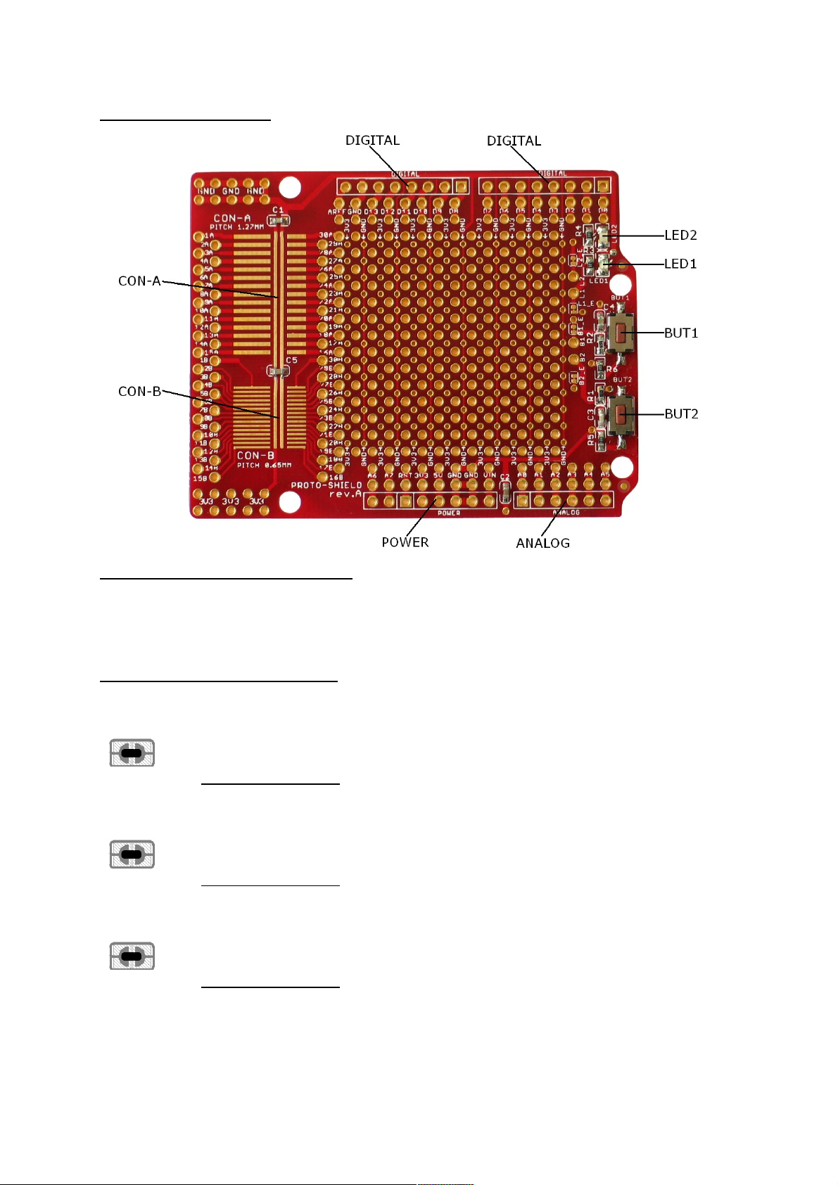
BOARD LAYOUT:
POWER SUPPLY CIRCUIT:
PROTO-SHIELD is power supplied via POWER connector from the ARDUINO
compatible board with which is used.
JUMPER DESCRIPTION:
L1_E
This jumper, when closed, LED1 is connected to D3 line.
This jumper, when opened, LED1 is connected to L1 pad.
Default state is closed.
L2_E
This jumper, when closed, LED2 is connected to D4 line.
This jumper, when opened, LED2 is connected to L2 pad.
Default state is closed.
B1_E
This jumper, when closed, BUT1 is connected to D6 line.
This jumper, when opened, BUT1 is connected to B1 pad.
Default state is closed.
Page 4
Page 5

B2_E
This jumper, when closed, BUT2 is connected to D7 line.
This jumper, when opened, BUT2 is connected to B2 pad
Default state is closed.
INPUT/OUTPUT:
Status Led with name LED1 (red) connected via jumper L1_E to DIGITAL
connector pin D3 – signal LED1.
Status Led with name LED2 (green) connected via jumper L2_E to DIGITAL connector pin D4 – signal LED2.
User button with name BUT1 connected via jumper B1_E to DIGITAL connector
pin D6 – signal BUT1.
User button with name BUT2 connected via jumper B2_E to DIGITAL connector
pin D7 – signal BUT2.
EXTERNAL CONNECTORS DESCRIPTION:
POWER:
Pin # Signal Name
1 A6
2 A7
3 RESET
4 VCC
5 +5V
6 GND
7 GND
8 +24V (VIN)
Note: This connector is not mounted on the board.
Page 5
Page 6

ANALOG:
Pin # Signal Name
1 A0
2 A1
3 A2
4 A3
5 A4(SDA)
6 A5(SCL)
Note: This connector is not mounted on the board.
DIGITAL:
Pin # Signal Name
1 D0(RXD)
2 D1(TXD)
3 D2
4 LED1
5 LED2
6 D5
7 BUT1
8 BUT2
Note: This connector is not mounted on the board.
Page 6
Page 7

DIGITAL:
Pin # Signal Name
1 D8
2 D9(LED2)
3 D10(#SS)
4 D11(MOSI)
5 D12(MISO)
6 D13(SCK/LED1)
7 GND
8 AREF
Note: This connector is not mounted on the board.
CON-A:
Note: This footprint can be used for mounting of SMD IC with 1.27mm pitch. Each of SMD
pads is routed to True Hole pad.
SMD
Pin #
True Hole pin #SMD
Pin #
True Hole pin
#
1 1A 2 2A
3 3A 4 4A
5 5A 6 6A
7 7A 8 8A
9 9A 10 10A
11 11A 12 12A
13 13A 14 14A
15 15A 16 16A
17 17A 18 18A
19 19A 20 20A
21 21A 22 22A
23 23A 24 24A
25 25A 26 26A
27 27A 28 28A
29 29A 30 30A
Page 7
Page 8

CON-B:
Note: This footprint can be used for mounting of SMD IC with 0.65mm pitch. Each of SMD
pads is routed to True Hole pad.
SMD
Pin #
True Hole pin #SMD
Pin #
True Hole pin
#
1 1B 2 2B
3 3B 4 4B
5 5B 6 6B
7 7B 8 8B
9 9B 10 10B
11 11B 12 12B
13 13B 14 14B
15 15B 16 16B
17 17B 18 18B
19 19B 20 20B
21 21B 22 22B
23 23B 24 24B
25 25B 26 26B
27 27B 28 28B
29 29B 30 30B
Page 8
Page 9

MECHANICAL DIMENSIONS:
Page 9
Page 10

ORDER CODE:
PROTO-SHIELD - assembled and tested board
How to order?
You can order to us directly or by any of our distributors.
Check our web www.olimex.com/dev for more info.
Revision history:
Board's revision Rev. A, May 2011
Manual's revision Rev. Initial, June 2011
Page 10
Page 11

Disclaimer:
© 2011 Olimex Ltd. All rights reserved. Olimex®, logo and combinations thereof, are registered
trademarks of Olimex Ltd. Other terms and product names may be trademarks of others.
The information in this document is provided in connection with Olimex products. No license, express
or implied or otherwise, to any intellectual property right is granted by this document or in
connection with the sale of Olimex products.
Neither the whole nor any part of the information contained in or the product described in this
document may be adapted or reproduced in any material from except with the prior written
permission of the copyright holder.
The product described in this document is subject to continuous development and improvements. All
particulars of the product and its use contained in this document are given by OLIMEX in good faith.
However all warranties implied or expressed including but not limited to implied warranties of
merchantability or fitness for purpose are excluded.
This document is intended only to assist the reader in the use of the product. OLIMEX Ltd. shall not
be liable for any loss or damage arising from the use of any information in this document or any error
or omission in such information or any incorrect use of the product.
Page 11
 Loading...