

Page 1
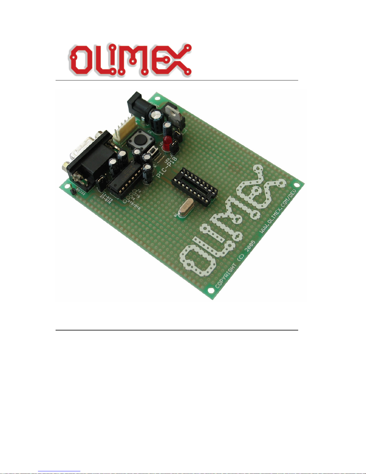
PIC-P18 development board
Users Manual
Rev.A, June 2007
Copyright(c) 2007, OLIMEX Ltd, All rights reserved
Page 2

INTRODUCTION:
PIC-P18 board is development board which allow you to prototype and
develop code for all Microchip’s PIC microcontrollers with 18 pins.
What you can do with PIC-P18? A lot of stuff let’s see what we have:
PIC-P18 have RS232 connector and driver, so you can interface your
PIC microcontroller to other embedded or PC with RS232. The RS232
driver have 4 lines Tx, Rx, CTS and jumper selectable RTS or DTR.
The pin labeled RX is output and should be connected to PIC UART Tx.
The pin labeled TX is input and should be connected to PIC UART Rx.
Note that MAX232 driver on the socket is 5V device, so if you decide
to run your PIC on 3.3V you should replace it with MAX3232 which
works on 3.3V
The on-board ICSP connector allow you to program the PIC on the
board without pulling it of the socket, by ICSP programmer like PICMCP, PIC-MCP-USB, PIC-PG1, PIC-PG2, PIC-PG3, PIC-PG4 or to
program and debug it with PIC-ICD2, PIC-ICD2-POCKET or PIC-ICD2TINY. IMPORTANT: all programmers provide power supply through
ICSP connector during the programming PIC-P18 should not be
powered via the external power jack!
The power supply circuit have diode bridge after the power supply jack
which allow you to power this board with both AC and DC power supply
adapters. The input voltage could be anything within the range +7.5 –
15V DC or 6-12V AC.
Voltage regulator is made with LM317 adjustable voltage regulator and
have jumper which selects what voltage you supply to the PIC
microcontroller +3.3V or +5V, so you can work with PICs on both low
and normal voltage.
The oscillator circuit is made with 20 Mhz crystal oscillator, so you
can run your PIC at maximum performance.
The RESET circuit is made with simple RC circuit and RESET push
button, the reason to not use RESET IC is that the board should
support both 3.3V and 5V operation while RESET ICs are on fixed
voltage.
PIC-P18 have user button for user input connected to PIC
microcontroller’s RB2 port. When RC2 port is initialized as INPUT you
will read “0” when the button is pressed and “1” when it is depressed.
Status LED is connected via jumper to PIC microcontroller’s RB3 port.
When your RB3 port is initialized as OUTPUT and set to “0” LED will
go ON, when RC2 port is set to “1” LED will go OFF.
PIC-P18 have handy GND pin for connection to oscilloscope.
Page 3
FEATURES:
• ICSP/ICD connector for programming and debugging
• RS232 interface with MAX232 IC o n socket
• DIL18 microcontroller socket
• Quartz crystal 20Mhz
• LED to RB3 through jumper
• user Button to RB2
• Reset button and circuit
• Power plug-in jack, accept AC and DC input
• selectable +3.3V / +5V power supply voltage regulator (3.3V when jumper is
closed)
• Extension slot on every uC pin
• Gird 100 mils
• GND bus
• Vcc bus
• Four mounting holes 3,3 mm (0,13")
• FR-4, 1.5 mm (0,062"), green soldermask, white silkscreen component print
• Dimensions 100x80 mm (3,9x3,15")
All boards produced by Olimex are ROHS compliant
Page 4

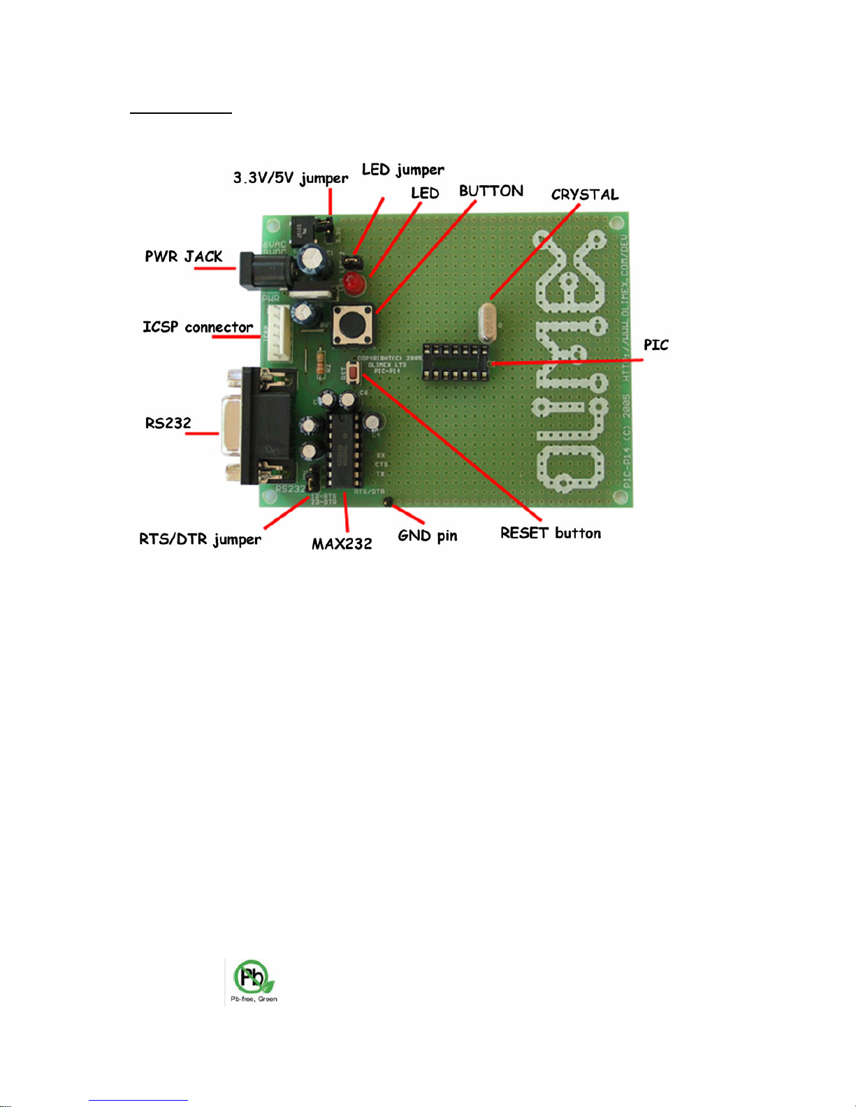
HARDWARE:
Page 5

SOFTWARE:
DEMO1:
PIC16F628-I/P BLINK LED
This is demo code which blinks the LED on PIC-P18 board.
Note:
LED jumper should be closed!
DEMO2: PIC16F628-I/P BUTTON read
This is demo code which show how to read BUTTON status and to switch
the LED ON when button is pressed and LED off when the button is
depressed.
DEMO3: PIC16F628-I/P RS232 send / receive routines
This is demo code, which show how to use the USART to send and receive
characters from host PC via RS232 cable.
The MAX232 by default is not connected to PIC on the board so you have to
solder two wires – one from RB2 (pin #8) of PIC16F628 Tx signal to MAX232
Tx labeled pin, and second from RB1 (pin #7) of PIC16F628 Rx signal to
MAX232 Rx labeled pin.
IMPORTANT: as seen from the schematic RB2 is also connected to the
User button, this means if you press the button d u ring the
communication the communication will be lost and you may burn your
PIC UART port!
You must program the HEX code to PIC16F628 and run the code.
If you programmed the PIC correctl y and wired the UART, when you open
Hyperterminal on your host PC computer with 9600 bps, 8 data bit, 1 stop
bit, No flow control and apply power supply to th e PIC-P18 every character
you type on the hyperterminal will be printed back with “*” i.e. if you type
“abc” you will receive “a*b*c*”.
Page 6

ORDER CODE:
PIC-P18
– assembled and tested (no kit, no soldering required)
PIC-P18/PCB – blank PCBs only
Revision history:
REV.A - create June 2007
Page 7

Disclaimer:
© 2007 Olimex Ltd. All rights reserved. Olimex®, log o and combinations thereof, are registered trademarks of
Olimex Ltd. Other terms and product names may be trademarks of others.
The information in this document is provided in connection with Olimex products. No license, express or implied
or otherwise, to any intellectual property right is granted b y this doc ument or in c onnection with the sale of Olimex
products.
Neither the whole nor any part of the information contained in or the product describe d in this document may be
adapted or reproduced in any material from except with the prior written permission of the copyright holder.
The product described in this document is subject to continuous development and improvements. All particulars of
the product and its use contained in this document are given by OLIMEX in good faith. Ho wever all warranties
implied or expressed including but not limited to implied warranties of merchantabi lity or fitness for purpose are
excluded.
This document is intended only to assist the reader i n the use of the prod uct. OLIMEX Ltd. shall not be liable for
any loss or damage arising from the use of any information in this document or an y error or omission in such
information or any incorrect use of the product.
 Loading...