

Page 1
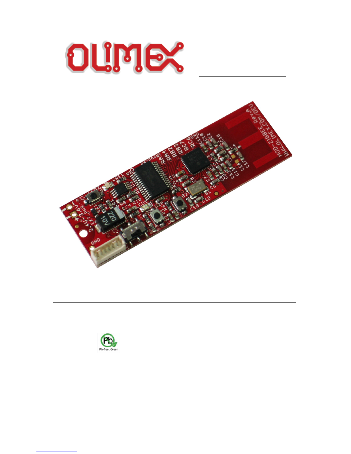
MOD-ZIGBEE development board
Users Manual
All boards produced by Olimex are ROHS compliant
Rev. B, March 2013
Copyright(c) 2011, OLIMEX Ltd, All rights reserved
Page 1 of 17
Page 2

INTRODUCTION
MOD-ZIGBEE features a bundle of 8bit PIC18 processor and an 802.15.4
compatible radio module that makes it easy to develop applications based on RF
communication and especially ZigBee based protocol stacks. In addition MODZIGBEE implements an on-board digital temperature sensor, for remote
temperature reporting.
BOARD FEATURES
• CPU: PIC18F26K20
• RF Transceiver – MRF24J40 IEEE 802.15.4™ standard compliant 2.4
GHz RF transceiver
• ICSP connector
• On-board antenna
• On-board temperature sensor – TCN75A
• Option for external power supply through EXT_PWR
• EXT/BAT switch
• Reset circuit
• two user buttons
• two status LEDs
• RST button
• +3V lithium battery holder
• PCB: FR-4, 1.00 mm (0,039"), solder mask, silkscreen component print
• Dimensions: 65.15x20.38 mm (2.56x0.80")
ELECTROSTATIC WARNING
The MOD-ZIGBEE board is shipped in protective anti-static packaging. The board
must not be subject to high electrostatic potentials. General practice for working
with static sensitive devices should be applied when working with this board.
BOARD USE REQUIREMENTS
Cables: The cable you will need depends on the programmer/debugger you
use. If you use PIC-ICD2-POCKET or PIC-Kit3 you will need 1.8 m AB USB cable.
Hardware: One of Olimex programmers/debuggers – PIC-ICD2-POCKET, PIC-
KIT3, or other compatible programming/debugging tool. Also
note that you would need adapter for the small ICSP connector (0.05''
step) - PIC-ICSP
Software: MPLAB IDE
Page 2 of 17
Page 3

PROCESSOR FEATURES
MOD-ZIGBEE use 28-pin Flash Microcontroller with nano Watt XLP Technology –
PIC18F26K20, with these features:
− High-Performance RISC CPU:
− C Compiler Optimized Architecture:
− Optional extended instruction set designed to optimize re-
entrant code
− 1024 bytes Data EEPROM
− 64 Kbytes Linear Program Memory Addressing
− 3936 bytes Linear Data Memory Addressing
− Up to 16 MIPS Operation
− 16-bit Wide Instructions, 8-bit Wide Data Path
− Priority Levels for Interrupts
− 31-Level, Software Accessible Hardware Stack
− 8 x 8 Single-Cycle Hardware Multiplier
− Flexible Oscillator Structure:
− Precision 16 MHz Internal Oscillator Block:
− Factory calibrated to ± 1%
− Software selectable frequencies range of 31 kHz to 16 MHz
− 64 MHz performance available using PLL – no external
components required
− Four Crystal modes up to 64 MHz
− Two External Clock modes up to 64 MHz
− 4X Phase Lock Loop (PLL)
− Secondary Oscillator using Timer1 @ 32 kHz
− Fail-Safe Clock Monitor:
− Allows for safe shutdown if peripheral clock stops
− Two-Speed Oscillator Start-up
− Special Microcontroller Features:
− Operating Voltage Range: 1.8V to 3.6V
− Self-Programmable under Software Control
− Programmable 16-Level High/Low-Voltage Detection (HLVD)
module:
− Interrupt on High/Low-Voltage Detection
− Programmable Brown-out Reset (BOR):
− With software enable option
− Extended Watchdog Timer (WDT):
Page 3 of 17
Page 4

− Programmable period from 4 ms to 131s
− Single-Supply 3V In-Circuit Serial Programming™ (ICSP™) via Two
Pins
− In-Circuit Debug (ICD) via Two Pins
− Extreme Low-Power Management with nanoWatt XLP:
− Sleep mode: < 100 nA @ 1.8V
− Watchdog Timer: < 800 nA @ 1.8V
− Timer1 Oscillator: < 800 nA @ 32 kHz and 1.8V
− Analog Features:
− Analog-to-Digital Converter (ADC) module:
− 10-bit, 10 Channels
− Auto-acquisition capability
− Conversion available during Sleep
− One 1.2V Fixed Voltage Reference (FVR) channel
− Independent input multiplexing
− Analog Comparator module:
− Two rail-to-rail analog comparators
− Independent input multiplexing
− Voltage Reference (CVREF) module
− Programmable (% VDD), 16 steps
− Two 16-level voltage ranges using VREF pins
− Peripheral Highlights:
− 24 I/O Pins plus 1 Input-only Pin:
− High-Current Sink/Source 25 mA/25 mA
− Three programmable external interrupts
− Four programmable interrupt-on-change
− Eight programmable weak pull-ups
− Programmable slew rate
− Master Synchronous Serial Port (MSSP) module
− 3-wire SPI
− I
2
C™ Master and Slave modes with address mask
− Enhanced Universal Synchronous Asynchronous Receiver
Transmitter (EUSART) module:
− Supports RS-485, RS-232 and LIN
− RS-232 operation using internal oscillator
− Auto-Wake-up on Break
− Auto-Baud Detect
Page 4 of 17
Page 5
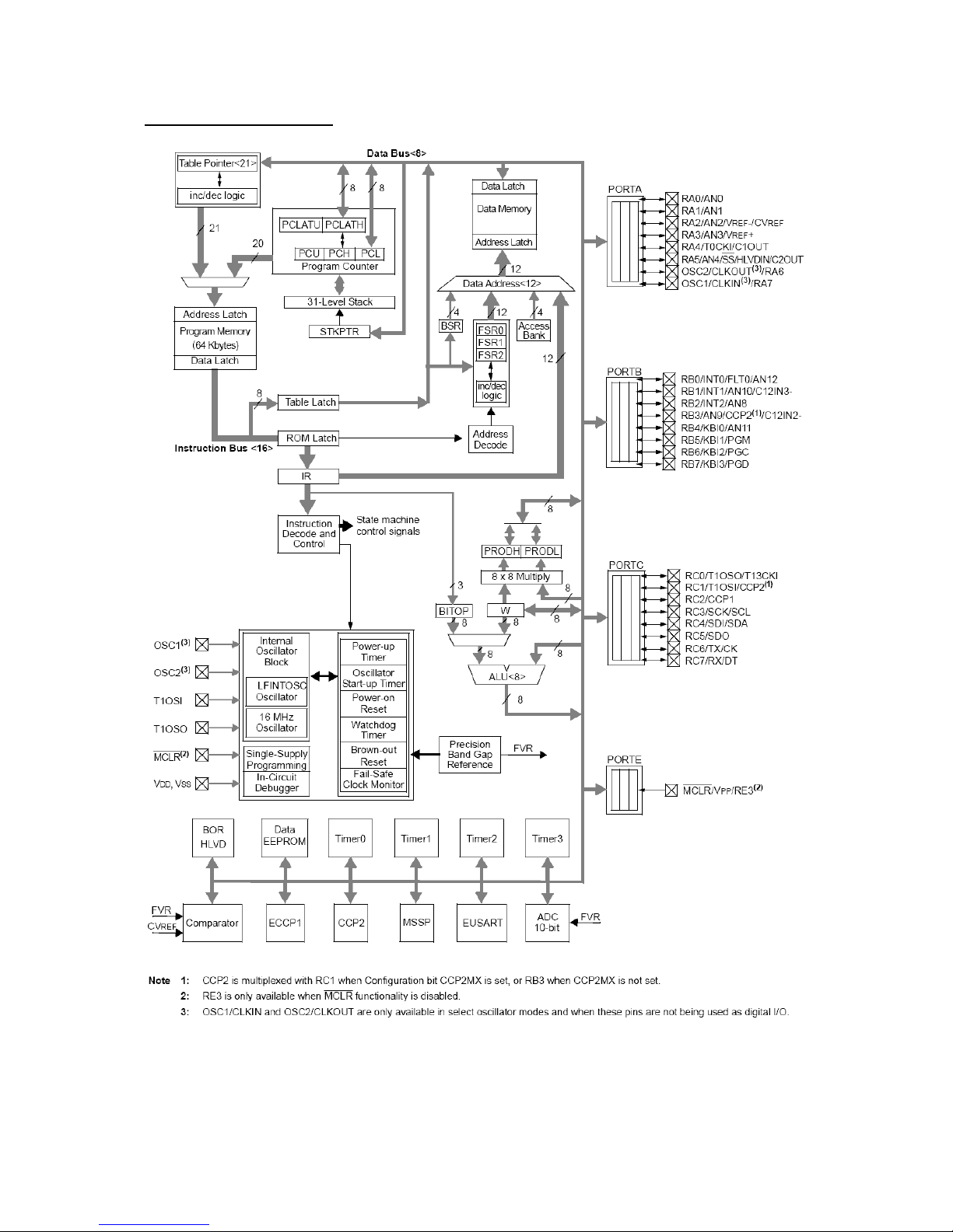
BLOCK DIAGRAM
Page 5 of 17
Page 6
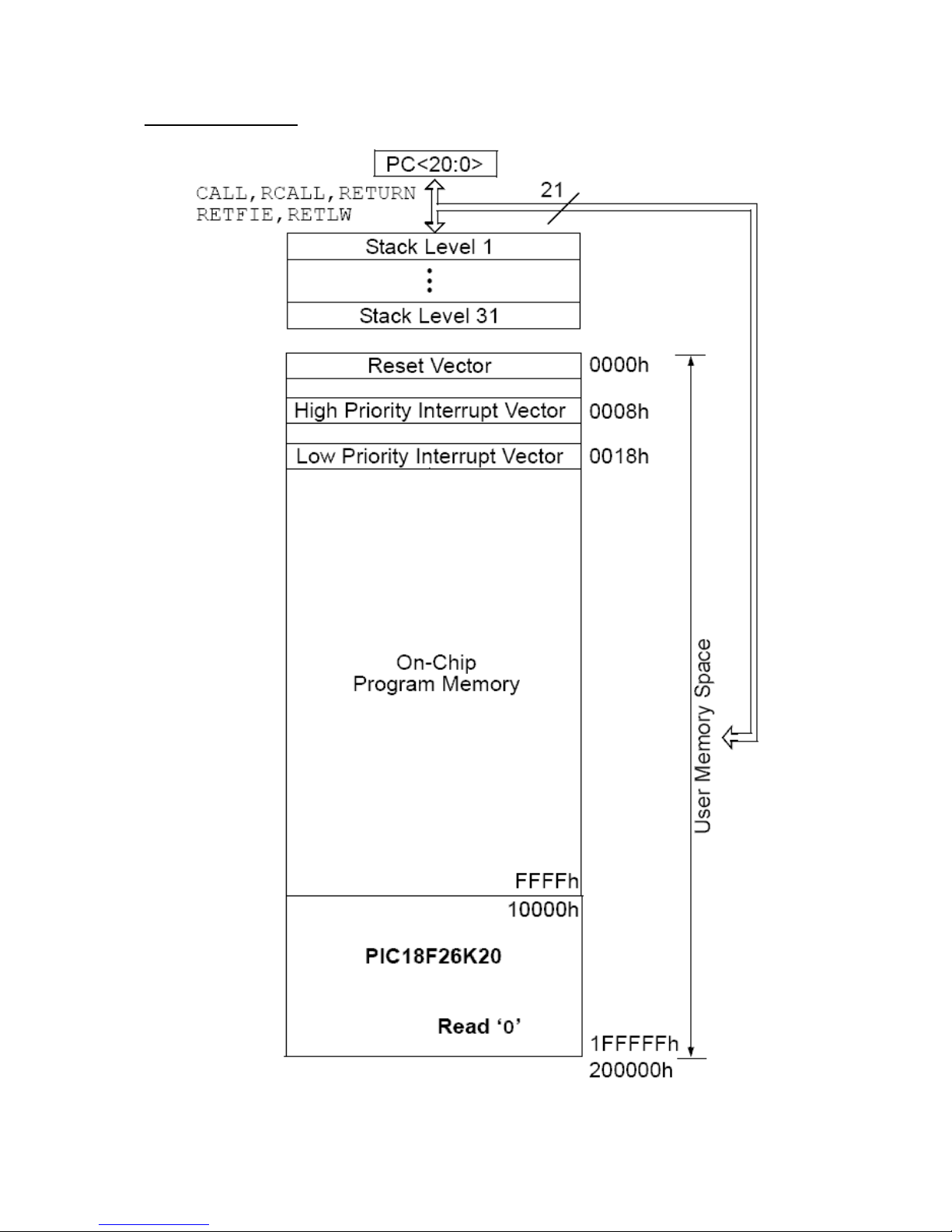
MEMORY MAP
Page 6 of 17
Page 7

RF TRANSCEIVER FEATURES
− IEEE 802.15.4™ Standard Compliant RF Transceiver
− Supports ZigBee®, MiWi™, MiWi P2P and Proprietary Wireless Networking
Protocols
− Simple, 4-Wire SPI Interface
− Integrated 20 MHz and 32.768 kHz Crystal Oscillator Circuitry
− Low-Current Consumption:
− RX mode: 19 mA (typical)
− TX mode: 23 mA (typical)
− Sleep: 2 μA (typical)
− RF/Analog Features:
− ISM Band 2.405-2.48 GHz Operation
− Data Rate: 250 kbps (IEEE 802.15.4); 625 kbps (Turbo mode)
− -95 dBm Typical Sensitivity with +5 dBm Maximum Input Level
− +0 dBm Typical Output Power with 36 dB TX Power Control Range
− Differential RF Input/Output with Integrated TX/RX Switch
− Integrated Low Phase Noise VCO, Frequency Synthesizer and PLL
Loop Filter
− Digital VCO and Filter Calibration
− Integrated RSSI ADC and I/Q DACs
− Integrated LDO
− High Receiver and RSSI Dynamic Range
− MAC/Baseband Features:
− Hardware CSMA-CA Mechanism, Automatic Acknowledgement
Response and FCS Check
− Independent Beacon, Transmit and GTS FIFO
− Supports all CCA modes and RSSI/ED
− Automatic Packet Retransmit Capability
− Hardware Security Engine (AES-128) with CTR, CCM and CBC-MAC
modes
− Supports Encryption and Decryption for MAC Sublayer and Upper
Layer
Page 7 of 17
Page 8

RF TRANSCEIVER BLOCK DIAGRAM
Page 8 of 17
Page 9

RF TRANSCEIVER MEMORY MAP
Page 9 of 17
Page 10

SCHEMATIC
SIDE_WT CM-T R(3X4)
SIDE_WT CM-TR (3X4)
BTH-V20-LF
0.5pF/5 0V/+-0 .25pF/ COG
0.5pF/ 50V/+ -0.25pF/ COG
NP
1pF/50 V/+-0.2 5pF/COG
1pF/50V/+-0.25pF/COG
100pF/50V/+-5%/COG
100n/10V/+ -10%/X 5R
47pF/50V/+ -5%/CO G
47pF/50V/+ -5%/CO G
100n/10V/+ -10%/X 5R
10n/25V/+ -10%/X 7R
47pF/50V /+-5%/CO G
47pF/50V /+-5%/C OG
47pF/50V /+-5%/C OG
10n/25V/+ -10%/X 7R
1uF/6.3V/ +-20%/X 5R
27pF/50V/+-5%/COG
27pF/50V/+-5%/COG
1000 uF/6. 3V/8x1 2/low_ ESR
100nF
100nF
100nF
100nF 100nF
ZD8.2 V/0.2W /SMD
SWITCH_IS-1390
NA
WU6S
3.3nH/ +-0.3nH/4 00m A/120 .0mO
6.8nH/+ -5%/320 mA/3 00.0m O
8.2nH/+-5 %/320 mA/3 50.0m O 5.6nH/+ -0.3nH/3 40m A/190 .0mO
red green
20.0000MHz/18pF/5x3.2
10k
330R
10k 10K
10K
10K 10K
560R 560R
330R 330R
330R
IT1185AU2
MRF24J40-I/M
PIC18F26K20-I/SS
TCN75AVUA
3V
3V
3V
3V
3V
3V 3V
3V3
3V
3V
3V
IDC10S-PCB
#SS
#SS
B1
B1
B2
B2
LED1
LED1
LED2
LED2
MISO
MISO
MISO
MOSI
MOSI
MOSI
PGC
PGC
PGD
PGD
RF_CS
RF_CS
RF_INT
RF_INT
RF_RST
RF_RST
RF_WAKE
RF_WAKE
RST
RST
RST_ICSP
RST_ICSP
RXD
RXD
SCK
SCK
SCK
SCL
SCL
SCL
SDA
SDA
SDA
TEMP_INT
TEMP_INT
TXD
TXD
B1
B2
+-
BAT
C1
C2
C3 C4
C5
C6
C7C8C9
C10
C11
C12
C13
C14
C15
C16
C17
C18
C19
C20
C21
C22
C23 C24
D1
1
1
2
2
3
3
4
4
5
5
6
6
EXT_BAT
1
2
EXT_PWR
GND
1
2
3
4
5
6
ICSP
L1
L2
L3 L4
LED1 LED2
RFP
1
PCB_ANT
GND
GND_
Q1
R1
R2
R3 R4
R5
R6 R7
R8 R9
R10 R11
R12
RA1
RA2
RA3
RB1
RB2
RST
CS
20
GND
6
GND
14
GND
22
GND
24
GND
25
GND
36
GPIO0
7
GPIO1
8
GPIO2
11
GPIO3
12
GPIO4
10
GPIO5
9
INT
16
LCAP
40
LPOSC1
28
LPOSC2
27
NC
23
NC
26
NC
29
NC
38
NC
30
OSC1
34
OSC2
33
RESET
13
RFN
3
RFP
2
SCK
19
SDI
18
SDO
17
VDD
1
VDD
4
VDD
5
VDD
21
VDD
31
VDD
32
VDD
35
VDD
37
VDD
39
WAKE
15
U1
AN12/FLT0/INT0/RB0
21
CCP2/C12IN2-/AN9/RB3
24
CK/TX/RC6
17
DT/RX/RC7
18
MCLR#/VPP/RE3
1
OSC1/CLKIN/RA7
9
OSC2/CLKOUT/RA6
10
P1B/AN8/INT2/RB2
23
P1C/C12IN3-/AN10/INT1/RB1
22
P1D/AN11/KBI0/RB4
25
PGC/KBI2/RB6
27
PGD/KBI3/RB7
28
PGM/KBI1/RB5
26
RA0/AN0/C12IN0
2
RA1/AN1/C12IN1
3
RA2/AN2/VREF-/CVREF/C2IN+
4
RA3/AN3/VREF+/C1IN+
5
RA4/T0CKI/C1OUT
6
RA5/AN4/SS#/HLVDIN/C2OUT
7
RC0/T1OSO/T13CKI
11
RC1/T1OSI/CCP2
12
RC2/CCP1/P1A
13
RC3/SCK/SCL
14
SDA/SDI/RC4
15
SDO/RC5
16
VDD
20
VSS
19
VSS
8
U2
A0
7
A1
6
A2
5
ALERT
3
GND
4
SCL
2
SDA
1
VDD
8
(#OS/INT )
U3
1 2
3 4
5 6
7 8
9 10
UEXT
MOD-ZIGBEE_rev_C
OLIMEX LTD, BULGARIA
https://www.olimex.com
+
+
RESET CIRCUIT
UEXTICSPBUTTONS&LEDS
I2C SENSOR
RADIO MODULE
2.4V-3.6V
Page 11

BOARD LAYOUT
POWER SUPPLY CIRCUIT
MOD-ZIGBEE may be power supplied in different ways: 2.4V - 3.6V via EXT_PWR;
via ICSP connector (useful for debugging); via BAT connector with +3V Lithium
battery (CR2032).
The programmed board power consumption is about 30mA with RF transceiver
active, and 10µA in deep sleep mode.
CLOCK CIRCUIT
Crystal Quartz 20 MHz connected to MRF24J40 pin 33 (OSC2) and pin 34 (OSC1).
RESET CIRCUIT
MOD-ZIGBEE reset circuit includes PIC18F26K20 pin 1 (MCLR#/VPP/RE3), R1
(10k) – pull-up, C21 (ZD8.2V/0.2W), R2 (330 Ohm), ICSP connector pin 1 and RST
button.
Page 11 of 17
Page 12

CONNECTOR DESCRIPTIONS
ICSP
Pin # Signal Name
1 RST-ICSP
2 3 V
3 GND
4 PGD
5 PGC
6 NC
EXT_PWR
Pin # Signal Name
1 2.4 V – 3.6 V
2 GND
*Note: There is no component mounted for this connector.
JUMPER DESCRIPTION
There are no jumpers on this board.
INPUT/OUTPUT
User button with name B1 – connected to PIC18F26K20 pin 26 (PGM/KBI1/RB5).
User button with name B2 – connected to PIC18F26K20 pin 25
(P1D/AN11/KBI0/RB4).
Reset button with name RST – connected to PIC18F26K20 pin 1
(MCLR#/VPP/RE3).
Status LED (red) with name LED1 – connected to PIC18F26K20 pin 2
(RA0/AN0/C12IN0).
Status LED (green) with name LED2 – connected to PIC18F26K20 pin 3
(RA1/AN1/C12IN1).
EXT/BAT switch – select between power supply from EXT_PWR and BAT.
Page 12 of 17
Page 13

MECHANICAL DIMENSIONS
Page 13 of 17
Page 14

AVAILABLE DEMO SOFTWARE
Available at https:// www.olimex.com
This sample project demonstrates the functionality of the onboard processor, the
radio transceiver and the thermometer. The demo is built upon the following
Microchip's freely distributed support libraries:
- Microchip MiWi Development Environment version 3.1
The demo defines 2 types of devices: Coordinator and End Devices.
According to Microchip MiWi specifications the MiWi network requires one
Coordinator and one or many End Devices. The demo consists of separate projects
for the Coordinator (called 'Coordinator') and End Devices (called 'EndDevice').
Upon startup the Coordinator forms a network with PAN ID 0x1234 on the
channel with the least amount of noise, LED1 is lit and the program starts waiting
for client devices to connect. Status messages are printed over UART and can be
displayed on a terminal program on a PC (please see next chapter). The Coordinator
is configured to accept connections from up to 10 devices. The Coordinator accepts
connections from any device that requests joining but will only recognise messages
about name and temperature of end devices using the other part of the demo.
Received and recognised messages are printed on the terminal and LED2 toggles at
any successful reception. Here is a sample terminal log from the operation of a
Coordinator:
-----------------------------------------------------------------------------------------
Input Configuration:
Button 1: RB5
Button 2: RB4
Output Configuration:
RS232 port
LED 1: RA0
LED 2: RA1
RF Transceiver: MRF24J40
Demo Instruction:
Power on the board until LED 1 lights up
to indicate it is ready to establish new
connections. Push Button 1 to perform
frequency agility procedure. Push Button
2 to unicast encrypted message. LED 2 will
be toggled upon receiving messages.
Feature MiWi DemMRF24J40 Node 1
Starting Active Scan...
Scan Channel 11
Scan Channel 12
Scan Channel 13
Scan Channel 14
Scan Channel 15
Scan Channel 16
Scan Channel 17
Scan Channel 18
Page 14 of 17
Page 15

Scan Channel 19
Scan Channel 20
Scan Channel 21
Scan Channel 22
Scan Channel 23
Scan Channel 24
Scan Channel 25
Scan Channel 26
Active Scanning Energy Scanning
Energy Scan Results:
Channel 11: -------------- 48
Channel 12: ------------- 41
Channel 13: ----------------- 58
Channel 14: ------------------ 5E
Channel 15: ----------------------- 76
Channel 16: -------------------- 67
Channel 17: ------------------------------ 9A
Channel 18: ---------------------- 72
Channel 19: ------------------------------------- BC
Channel 20: -------------------------------- A0
Channel 21: ------------------------------------------------ F0
Channel 22: -------------------------------------------------- FA
Channel 23: -------------------------------------------------- FB
Channel 24: ---------------------------------------------- E8
Channel 25: --------------------------------------- C4
Channel 26: ------------------------------------- BC
Start Wireless Communication on Channel 12
Start Connection on Channel 12
From 0081, RSSI B4, NAME: DEFAULT NAME 000
From 0081, RSSI BC, TEMPR: 24.0625oC
From 0081, RSSI C3, TEMPR: 24.0000oC
From 0081, RSSI C1, TEMPR: 24.0000oC
-----------------------------------------------------------------------------------------
Upon startup an End Device starts searching for a network with PAN ID
0x1234 on any available channel. If such a network is not found then the device
enters deep sleep mode and reattempts connecting after some time. When a suitable
network is found (formed by the Coordinator) the device joins it and sends to the
Coordinator its specific name and measured temperature. Then it enters deep sleep
mode and sends its measured temperature again after some time. The sleep may be
prematurely terminated by a press of any of the two buttons (not the RESET
button!).
If the Coordinator disappears for some reason the end device enters startup
state again.
*Note: With the introduction of MOD-LCD1x9 and MOD-ZIGBEE rev.B you have
the ability to make an assembly between the to and have status messages and
current temperature value displayed on the LCD, even when deep sleeping. To
enable this feature of the End Device demo just uncomment
"USING_MOD_LCD1x9" in 'main.c'.
Please read README.txt in demo source folder for more details.
Page 15 of 17
Page 16

ORDER CODE
MOD-ZIGBEE assembled and tested.
How to order?
You can order to us directly or by any of our distributors.
Check our web https:// www.olimex.com/ for more info.
Revision history:
REV. Initial - created March 2011
Rev. B - created January 2013
Page 16 of 17
Page 17

DISCLAIMER
© 2012 Olimex Ltd. Olimex®, logo and combinations thereof, are registered trademarks of Olimex
Ltd. Other product names may be trademarks of others and the rights belong to their respective
owners.
The information in this document is provided in connection with Olimex products. No license,
express or implied or otherwise, to any intellectual property right is granted by this document
or in connection with the sale of Olimex products.
The Hardware project is released with limited availability since it is a closed source project. You
may reproduce it for both your own personal use, and for commercial use. You will have to
provide a link to the original creator of the project http://www.olimex.com on any documentation
or website.
You may also modify the files, but you must then release them as well under the same terms.
Credit can be attributed through a link to the creator website: http://www.olimex.com
The software is released under GPL.
It is possible that the pictures in this manual differ from the latest revision of the board.
The product described in this document is subject to continuous development and improvements.
All particulars of the product and its use contained in this document are given by OLIMEX in good
faith. However all warranties implied or expressed including but not limited to implied warranties
of merchantability or fitness for purpose are excluded. This document is intended only to assist the
reader in the use of the product. OLIMEX Ltd. shall not be liable for any loss or damage arising
from the use of any information in this document or any error or omission in such information or
any incorrect use of the product.
This evaluation board/kit is intended for use for engineering development, demonstration, or
evaluation purposes only and is not considered by OLIMEX to be a finished end-product fit for
general consumer use. Persons handling the product must have electronics training and observe
good engineering practice standards. As such, the goods being provided are not intended to be
complete in terms of required design-, marketing-, and/or manufacturing-related protective
considerations, including product safety and environmental measures typically found in end
products that incorporate such semiconductor components or circuit boards.
Olimex currently deals with a variety of customers for products, and therefore our arrangement
with the user is not exclusive. Olimex assumes no liability for applications assistance, customer
product design, software performance, or infringement of patents or services described herein.
Page 17 of 17
Page 18

Mouser Electronics
Authorized Distributor
Click to View Pricing, Inventory, Delivery & Lifecycle Information:
Olimex Ltd.:
MOD-ZIGBEE
 Loading...