

Page 1
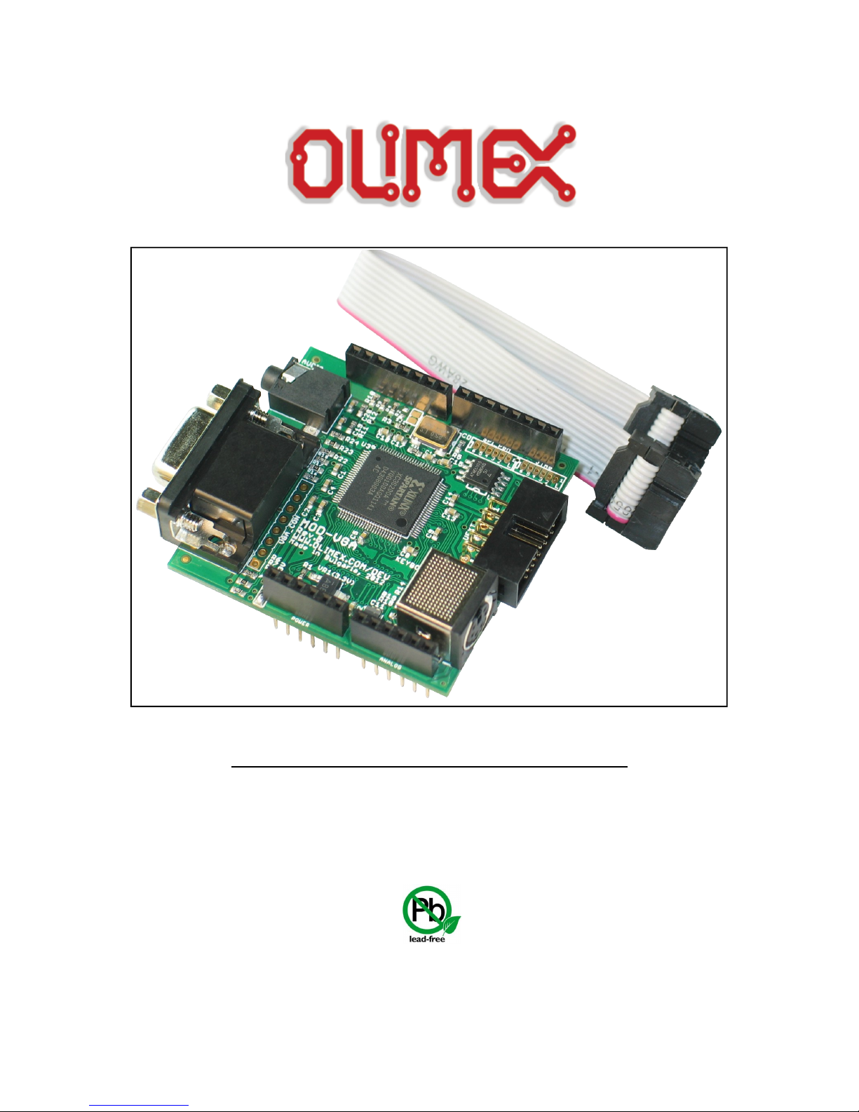
MOD-VGA and MOD-VGA-32
USER’S MANUAL
Document revision B, June 2016
Designed by OLIMEX Ltd, 2012
All boards produced by Olimex LTD are ROHS compliant
Page 2

OLIMEX© 2016 MOD-VGA user's manual
DISCLAIMER
© 2016 Olimex Ltd. Olimex®, logo and combinations thereof, are registered trademarks of Olimex Ltd.
Other product names may be trademarks of others and the rights belong to their respective owners.
The information in this document is provided in connection with Olimex products. No license, express
or implied or otherwise, to any intellectual property right is granted by this document or in connection
with the sale of Olimex products.
The Hardware project is released under the Creative Commons Attribution-Share Alike 3.0 United States
License. You may reproduce it for both your own personal use, and for commertial use. You will have to
provide a link to the original creator of the project http://www.olimex.com on any documentation or website.
You may also modify the files, but you must then release them as well under the same terms. Credit can be
attributed through a link to the creator website: http://www.olimex.com
The software is released under GPL.
It is possible that the pictures in this manual differ from the latest revision of the board.
The product described in this document is subject to continuous development and improvements. All
particulars of the product and its use contained in this document are given by OLIMEX in good faith.
However all warranties implied or expressed including but not limited to implied warranties of
merchantability or fitness for purpose are excluded. This document is intended only to assist the reader in the
use of the product. OLIMEX Ltd. shall not be liable for any loss or damage arising from the use of any
information in this document or any error or omission in such information or any incorrect use of the
product.
This evaluation board/kit is intended for use for engineering development, demonstration, or evaluation
purposes only and is not considered by OLIMEX to be a finished end-product fit for general consumer use.
Persons handling the product must have electronics training and observe good engineering practice
standards. As such, the goods being provided are not intended to be complete in terms of required design-,
marketing-, and/or manufacturing-related protective considerations, including product safety and
environmental measures typically found in end products that incorporate such semiconductor components or
circuit boards.
Olimex currently deals with a variety of customers for products, and therefore our arrangement with the user
is not exclusive. Olimex assumes no liability for applications assistance, customer product design, software
performance, or infringement of patents or services described herein.
THERE IS NO WARRANTY FOR THE DESIGN MATERIALS AND THE
COMPONENTS USED TO CREATE MOD-VGA. THEY ARE CONSIDERED
SUITABLE ONLY FOR MOD-VGA.
Page 2 of 23
Page 3

OLIMEX© 2016 MOD-VGA user's manual
Table of Contents
DISCLAIMER ............................................................................................................. 2
CHAPTER 1: OVERVIEW ........................................................................................ 5
1. Introduction to the chapter ....................................................................................................... 5
1.1 Features ..................................................................................................................................... 5
1.2 Target market and purpose of the board ............................................................................... 6
1.3 Organization ............................................................................................................................. 6
CHAPTER 2: SETTING UP THE MOD-VGA BOARD ......................................... 7
2. Introduction to the chapter ....................................................................................................... 7
2.1 Electrostatic warning ............................................................................................................... 7
2.3 Requirements ........................................................................................................................... 7
2.4 Powering the board .................................................................................................................. 8
2.5 Running an example using Olimex OLIMEXINO-328 ........................................................ 8
CHAPTER 3: MOD-VGA BOARD DESCRIPTION .............................................. 9
3. Introduction to the chapter ....................................................................................................... 9
3.1 Layout (top view) ..................................................................................................................... 9
3.2 Layout (bottom view) ............................................................................................................. 10
CHAPTER 4: The XILINX SPARTAN-3 XC3S200 FPGA ................................... 11
4. Introduction to the chapter ..................................................................................................... 11
4.1 The XILINX SPARTAN-3 XC3S200 FPGA ........................................................................ 11
CHAPTER 6: CONNECTORS, HARDWARE, PINOUTS ................................... 13
6. Introduction to the chapter ..................................................................................................... 13
6.1 FPGA programming options ................................................................................................. 13
6.1.1 SPI_PGM pinholes .............................................................................................................. 13
6.1.2 JTAG pinholes ..................................................................................................................... 14
6.2 UEXT connector ..................................................................................................................... 14
6.3 Audio connector ..................................................................................................................... 15
6.4 VGA video connector ............................................................................................................. 15
6.5 Arduino shield connector ...................................................................................................... 16
6.6 Keyboard connector .............................................................................................................. 17
6.7 Jumper description ................................................................................................................ 17
6.7.1 5V/3V .................................................................................................................................... 17
6.7.2 SJ1 ........................................................................................................................................ 17
CHAPTER 8: SCHEMATICS .................................................................................. 18
8. Introduction to the chapter ..................................................................................................... 18
8.1 Eagle schematic ...................................................................................................................... 18
8.2 Physical dimensions ............................................................................................................... 20
CHAPTER 9: REVISION HISTORY AND SUPPORT ........................................ 21
9. Introduction to the chapter ..................................................................................................... 21
Page 3 of 23
Page 4

OLIMEX© 2016 MOD-VGA user's manual
9.1 Document revision ................................................................................................................. 21
9.2 Board revision ........................................................................................................................ 21
9.3 Useful web links and purchase codes ................................................................................... 22
9.4 Product support ..................................................................................................................... 23
Page 4 of 23
Page 5

OLIMEX© 2016 MOD-VGA user's manual
CHAPTER 1: OVERVIEW
1. Introduction to the chapter
Thank you for choosing the MOD-VGA video shield from Olimex! This document provides a
user’s guide for the Olimex MOD-VGA. As an overview, this chapter gives the scope of this
document and lists the board’s features. The document’s organization is then detailed.
The MOD-VGA development board enables code development of applications running on the
FPGA from the SPARTAN-3A family, manufactured by XLINIX.
MOD-VGA is an open-source, open-hardware project and all documentation is available to the
customer. It is tested and working with OLIMEX AVR boards.
1.1 Features
MOD-VGA is a game adapter for the Arduino – or anything else with an SPI interface – built as a
single shield that stacks up on top of the Arduino and has plugs for a VGA monitor and stereo
speakers. The board is based on the open-source, open-hardware GAMEDUINO project by
excamera. For more information on the original project please visit
http://excamera.com/sphinx/gameduino/.
Video output is 400x300 pixels in 512 colors
• all color processed internally at 15-bit precision
• compatible with any standard VGA monitor (800x600 @ 72Hz)
• background graphics
• 512x512 pixel character background
• 256 characters, each with independent 4 color palette
• pixel-smooth X-Y wraparound scroll
• foreground graphics
• each sprite is 16x16 pixels with per-pixel transparency
• each sprite can use 256, 16 or 4 colors
• four-way rotate and flip
• 96 sprites per scan-line, 1536 texels per line
• pixel-perfect sprite collision detection
Audio output is a stereo 12-bit frequency synthesizer
• 64 independent voices 10-8000 Hz
• per-voice sine wave or white noise
• sample playback channel
Page 5 of 23
Page 6

OLIMEX© 2016 MOD-VGA user's manual
1.2 Target market and purpose of the board
The board follows the Arduino shield connector platform and can be mounted directly on 3.3V
Arduino boards. Note that if your Arduno board doesn't have 3.3V operating mode you would need
level shifter. The board comes with examples and libraries compatible with Arduino IDE (after
importing the library and the examples provided on our web-site in Arduino).
The board is tested and working with our OLIMEXINO-328:
https://www.olimex.com/Products/Duino/AVR/OLIMEXINO-328/open-source-hardware.
The board has hardware compatibility with any 3.3V Arduino-like board and also Maple boards,
Duinomite boards, and basically every board that follows the Arduino shield connector platform and
can operate at 3.3V. However, the software support for all boards except for the Arduino-compatible
AVR ones is not still implemented and might require extended software knowledge to be
implemented.
Customers have full access to the technical documentation of the board. The software is released
under General Purpose License and the board is considered open-hardware.
1.3 Organization
Each section in this document covers a separate topic, organized as follow:
– Chapter 1 is an overview of the board usage and features
– Chapter 2 provides a guide for quickly setting up the board and software notes
– Chapter 3 contains the general board diagram and layout
– Chapter 4 describes the component that is the heart of the board: the XILINX Spartan-3A
FPGA
– Chapter 5 is an explanation of the control circuitry associated with the microcontroller to
reset. Also shows the clocks on the board
– Chapter 6 covers the connector pinout, peripherals and jumper description
– Chapter 7 shows the memory map
– Chapter 8 provides the schematics
– Chapter 9 contains the revision history, useful links and support information
Page 6 of 23
Page 7

OLIMEX© 2016 MOD-VGA user's manual
CHAPTER 2: SETTING UP THE MOD-VGA BOARD
2. Introduction to the chapter
This section helps you set up the MOD-VGA development board for the first time. Please consider
first the electrostatic warning to avoid damaging the board, then discover the hardware and software
required to operate the board.
The procedure to power up the board is given, and a description of the default board behavior is
detailed.
2.1 Electrostatic warning
MOD-VGA is shipped in a protective anti-static package. The board must not be exposed to high
electrostatic potentials. A grounding strap or similar protective device should be worn when
handling the board. Avoid touching the component pins or any other metallic element.
2.3 Requirements
In order to set up the MOD-VGA optimally, the following items are required (separated in hardware
and software requirements).
Hardware:
- Host board with Arduino platform connectors (For example OLIMEXINO-328 or OLIMEXINIO32U4) that can operate at 3.3V (or level shifter)
- VGA monitor
- PS2 keyboard (that can operate at 5V or 3V)
- Audio output device
Software:
- Arduino-IDE
- A library that needs to be imported in Arduino-IDE and can be found at our web-site at MODVGA's page
Page 7 of 23
Page 8

OLIMEX© 2016 MOD-VGA user's manual
2.4 Powering the board
The board gets powered when mounted on compatible Arduino board by 3.3V.
Important: MOD-VGA is not 5V tolerant.
The SPI lines coming from the main board go to the XYLNIX SPARTAN-3A chip via 47 Ohm
resistors and the GPIO pins of SPARTAN-3A have an absolute maximum of 4.6V!
2.5 Running an example using Olimex OLIMEXINO-328
First place properly the library for Arduino that can be found on the device's web page:
https://www.olimex.com/Products/Modules/Interface/MOD-VGA/
Make sure that the OLIMEXINO-328 board operates at 3.3V! There is a switch that modifies the
operating voltage of the board – either 3.3V or 5V operation.
Then start Arduino and open the corresponding to OLIMEXINO-328 board configuration:
Tools -> Board -> Arduino Duemilanove w\ATmega 328
Then program for example:
Files -> Examples -> Gameduino -> Audio -> player
We should see a graphic and there should be sound (if we have audio output device connected).
Page 8 of 23
Page 9

OLIMEX© 2016 MOD-VGA user's manual
CHAPTER 3: MOD-VGA BOARD DESCRIPTION
3. Introduction to the chapter
Here you get acquainted with the main parts of the board. Note the names used on the board might
differ from the names used below to describe them. For the actual names check the MOD-VGA
board itself.
3.1 Layout (top view)
Page 9 of 23
Page 10

OLIMEX© 2016 MOD-VGA user's manual
3.2 Layout (bottom view)
Note the base MOD-VGA version doesn't have the additional memory present on the picture of
MOD-VGA-32.
Page 10 of 23
Page 11

OLIMEX© 2016 MOD-VGA user's manual
CHAPTER 4: The XILINX SPARTAN-3 XC3S200 FPGA
4. Introduction to the chapter
In this chapter is located the information about the heart of MOD-VGA – its controller. The
information is a modified version of the datasheet provided by its manufacturers.
4.1 The XILINX SPARTAN-3 XC3S200 FPGA
Low-cost, high-performance logic solution for high-volume, consumer-oriented applications
✔ 4320 logic cells
SelectIO™ interface signaling
✔ 173 I/O pins
✔ 622+ Mb/s data transfer rate per I/O
✔ 18 single-ended signal standards
✔ 8 differential I/O standards including LVDS, RSDS
✔ Termination by Digitally Controlled Impedance
✔ Signal swing ranging from 1.14V to 3.465V
✔ Double Data Rate (DDR) support
✔ DDR, DDR2 SDRAM support up to 333 Mbps
Logic resources
✔ Abundant logic cells with shift register capability
✔ Wide, fast multiplexers
✔ Fast look-ahead carry logic
✔ Dedicated 18 x 18 multipliers
✔ JTAG logic compatible with IEEE 1149.1/1532
SelectRAM™ hierarchical memory
✔ 216 Kbits of total block RAM
✔ 30 Kbits of total distributed RAM
Digital Clock Manager (up to four DCMs)
✔ Clock skew elimination
✔ Frequency synthesis
✔ High resolution phase shifting
Eight global clock lines and abundant routing
✔ Fully supported by Xilinx ISE® and WebPACK™ software development systems
✔ MicroBlaze™ and PicoBlaze™ processor, PCI®, PCIExpress® PIPE Endpoint, and
other IP cores
✔ Pb-free packaging options
✔ Automotive Spartan-3 XA Family variant
Page 11 of 23
Page 12

OLIMEX© 2016 MOD-VGA user's manual
For comprehensive information on the microcontroller visit the Xilinx’s web page for a datasheet.
At the moment of writing the FPGA's datasheet can be found at the following link:
http://www.xilinx.com/support/documentation/data_sheets/ds099.pdf
Page 12 of 23
Page 13

OLIMEX© 2016 MOD-VGA user's manual
CHAPTER 6: CONNECTORS, HARDWARE, PINOUTS
6. Introduction to the chapter
In this chapter are presented the connectors that can be found on the board all together with their
pinout and notes about them. Jumpers functions are described. Notes and info on specific
peripherals are presented. Notes regarding the interfaces are given.
6.1 FPGA programming options
There are couple of options provided for programming the Xlinx FPGA. Both of them are located
near the DIGITAL connector from the Arduino platform. Note that both of them lack headers. The
SPI_PGM and JTAG are discussed below.
6.1.1 SPI_PGM pinholes
The SPI_PGM interface lacks connector. You can mount for instance WU06S for easier interfacing.
SPI_PGM
PIN# SIGNAL NAME
1 FLASH_SO
2 FLASH_SI
3 FLASH_SCK
4 #FLASH_CS
5 GND
6 +3.3V
Page 13 of 23
Page 14

OLIMEX© 2016 MOD-VGA user's manual
6.1.2 JTAG pinholes
The JTAG interface lacks connector. You can mount plastic header (for instance WU06S) for easier
interfacing.
JTAG
PIN# SIGNAL NAME
1 +3.3V
2 TCK
3 TDO
4 TMS
5 TDI
6 GND
6.2 UEXT connector
Note that the signals on the UEXT connector are multiplexed with the respective header pins from
the Arduino shield connector.
Note that the SPI interface can also be found on the Arduino shield connector.
For more info on the UEXT connector please visit:
https://www.olimex.com/Products/Modules/UEXT/
UEXT connector
Pin # Signal Name Processor Pin #
1 +3.3V -
2 GND -
3 Not Connected -
4 INT 78
5 Not Connected -
6 INT 78
7 UEXT_MISO 86
8 UEXT_MOSI 85
9 UEXT_CLK 84
10 UEXT_SSEL 88
Page 14 of 23
Page 15

OLIMEX© 2016 MOD-VGA user's manual
6.3 Audio connector
Standard audio jack and phone jack are mounted for the audio interfacing.
Headphones/Audio out connector
Pin# SIGNAL NAME Processor Pin#
1 LINE_OUT_L 99
3 LINE_OUT_R 98
2 GND GND pins
The headphones resistance is 16 Ohms!
6.4 VGA video connector
The female DA-15 connector is used for video output on a monitor.
Note that there is also a row of pinholes near the DA-15 named VGA_CON – it gives access to the
used signals only. Check the tables below for pinout of both the DB15 and the VGA_CON.
VGA_CON
PIN# SIGNAL
1 VGA_R
2 VGA_G
3 VGA_B
4 H_SYNC
5 V_SYNC
6 +5V
7 GND
8 +3.3V
Page 15 of 23
Page 16

OLIMEX© 2016 MOD-VGA user's manual
You may find the pinout of the DA-15 connector on the next page.
VGA DB15 connector
GPIO Pin# Signal Name GPIO Pin# Signal Name
1 VGA_R 2 VGA_G
3 VGA_B 4 Not Connected
5 GND 6 GND
7 GND 8 GND
9 GND 10 GND
11 Not Connected 12 Not Connected
13 VGA_HSYNC 14 VGA_VSYNC
15 Not Connected 16 Not Connected
6.5 Arduino shield connector
Pad Name Signal Pad Name Signal
POWER ANALOG
RST Not connected A0 Not connected
3V3 3V3 A1 Not connected
5V 5V A2 Not connected
GND GROUND A3 Not connected
GND GROUND A4 Not connected
VIN Not connected A5 Not connected
DIGITAL #1 DIGITAL #2
D0 Not connected D8 Not connected
D1 Not connected D9 UEXT_SSEL
D2 INT D10 SPI_CS
D3 Not connected D11 SPI_MOSI
D4 Not connected D12 SPI_MISO
D5 Not connected D13 SPI_CLK
D6 PS2_DATA GND Not connected
D7 PS2_CLK AREF Not connected
Page 16 of 23
Page 17

OLIMEX© 2016 MOD-VGA user's manual
6.6 Keyboard connector
The key board connector is a standard PS2 one requiring MINI-DIN cable connector. By default it
operates at 5V. The voltage available for the keyobard can be changed by modifying jumper 5V/3V.
6.7 Jumper description
Please note that both jumpers on the board are SMT type. If you feel insecure of your
soldering/cutting technique it is better not to try to adjust the jumpers.
6.7.1 5V/3V
Those jumpers control the voltage available at the PS2 keyboard connector.
The default position is 5V.
6.7.2 SJ1
SJ1 jumper controls whether SPI SSEL line that is available on the UEXT pin #10 is also connected
to pin D9 from the digital connector of the Arduino interface. If the jumper is connected then the
mentioned multiplexing is present.
The default position is closed (SPI CS is available simultaneously at pin #10 of the UEXT
connector and at pin D9 from the Arduino shield connector).
Page 17 of 23
Page 18

OLIMEX© 2016 MOD-VGA user's manual
CHAPTER 8: SCHEMATICS
8. Introduction to the chapter
In this chapter are located the schematics describing logically and physically MOD-VGA.
8.1 Eagle schematic
The EAGLE schematic is situated on the next page for quicker reference. It can also be found on
the web-page of the device. The schematic and board files are released under the Creative
Commons Attribution-Share Alike 3.0 United States License. You may reproduce it for both your
own personal use, and for commercial use. You will have to provide a link to the original creator of
the project (https://www.olimex.com) on any documentation or website.
Page 18 of 23
Page 19

OLIMEX© 2016 MOD-VGA user's manual
Page 19 of 23
U3
default-5V_closed
JACK-3PINSCJ325P00XG0B02G
100n
100n
100n
100n
100n
NA(100n)
100n
100n
10uF/6.3V
47uF/6.3V
100n
100n
100n
100n
100n
100n
100n
10n 10n
10n
100n
22uF/6.3V
100n
22uF/6.3V
100n
25MHz
WU06S(NA)
+5V
1.2V
1.2V
1.2V
1.2V
1.2V
+5V
+5V
MD6R MINI-DIN
240R
NA
47
47
3.9k
470
1k
1.8k
47
47
3.9k
3.9k
10k
10k
240R
470
1k
1.8k
240R
NA(10k)
22
470
1k
1.8k
5.1k
5.1k
NA
NA
close
WU06S(NA)
2*PN1x6_8,5/11mm+2*PN1x8_8,5/11mm
NA(K6R4016V1D)
XC3S200A-4VQ100C
AT45DB041D-SU
K4S561632C-TC/L75
BH10R
3.3V
3.3V
3.3V
3.3V
3.3V
3.3V
3.3V
3.3V
3.3V
3.3V
3.3V
3.3V
3.3V3.3V
3.3V
3.3V
3.3V
3.3V
3.3V
3.3V
NA
LM1117IMPX-ADJ
XD[0..15]
#FLASH_CS
#FLASH_CS
#FLASH_CS
25MHZ
25MHZ
B1
B1
B2
B2
B3
B3
FLASH_SCK
FLASH_SCK
FLASH_SCK
FLASH_SI
FLASH_SI
FLASH_SI
FLASH_SO
FLASH_SO
FLASH_SO
G1
G1
G2
G2
G3
G3
HSYNC
HSYNC
INT
INT
INT
LINE_OUT_L
LINE_OUT_R
PS2_CLK
PS2_CLK
PS2_DATA
PS2_DATA
R1
R1
R2
R2
R3
R3
RAM_#CS
RAM_#CS RAM_#CS
SPI_CLK
SPI_CLK
SPI_CS
SPI_CS
SPI_MISO
SPI_MISO
SPI_MOSI
SPI_MOSI
TCK
TCK
TDI
TDI
TDO
TDO
TMS
TMS
UEXT_CLK
UEXT_MISO
UEXT_MOSI
UEXT_SSEL
VSYNC
VSYNC
XA0
XA0
XA0 XA0
XA1
XA1
XA1 XA1
XA2
XA2
XA2 XA2
XA3
XA3
XA3 XA3
XA4
XA4
XA4 XA4
XA5
XA5
XA5 XA5
XA6
XA6
XA6 XA6
XA7 XA7
XA7
XA7
XA8
XA8
XA8 XA8
XA9
XA9
XA9 XA9
XA10
XA10
XA10 XA10
XA11
XA11
XA11 XA11
XA12
XA12
XA12 XA12
XA13
XA13
XA13 XA13
XA14
XA14
XA14
XA14
XA15/SDRAM_CLK XA15/SDRAM_CLK
XA15/SDRAM_CLK
XA15/SDRAM_CLK
XA16/#RASXA16/#RAS
XA16/#RA S
XA16/#RA S
XA17/#CAS
XA17/#CAS
XA17/#CA S
XA17/#CA S
XD0
XD0 XD0
XD0
XD1
XD1 XD1
XD1
XD2
XD2 XD2
XD2
XD3
XD3 XD3
XD3
XD4
XD4 XD4
XD4
XD5
XD5 XD5
XD5
XD6
XD6 XD6
XD6
XD7
XD7 XD7
XD7
XD8
XD8 XD8
XD8
XD9
XD9 XD9
XD9
XD10
XD10 XD10
XD10
XD11
XD11 XD11
XD11
XD12
XD12 XD12
XD12
XD13
XD13 XD13
XD13
XD14
XD14 XD14
XD14
XD15
XD15 XD15
XD15
XOE
XOE
XOE
XWE
XWE
XWE XWE
123
5V/3V
AUDIO
C1
C2
C3
C4
C5
C7
C8
C9
C10
C11
C12
C13
C14
C15
C16
C17
C18
C19 C20
C21
C22
C23
C24
C25
C26
1
3
4
2
CD
1
2
3
4
5
6
JTAG
1
1
2
2
3
3
4
4
5
5
6
6
NC1
NC2
SHIELD
PS2_KEYBOARD
R1
R2 R3
R4
R5
R6
R7
R8
R9
R10
R11
R12
R13
R14
R15
R16
R17
R18
R19
R20
R21
R22
R23
R24
R25
R26
R27
R28
1 2
SJ1
1
2
3
4
5
6
SPI_PGM
3V3
5V
A0
A1
A2
A3
A4
A5
AREF
D0
D1
D2
D3
D4
D5
D6
D7
D8
D9
D10
D11
D12
D13
GND
GND
GND
RST
VIN
U1
BHE
40
BLE
39
CS
6
OE
41
WE
17
A0
1
A1
2
A2
3
A3
4
A4
5
A5
18
A6
19
A7
20
A8
21
A9
22
A10
23
A11
24
A12
25
A13
26
A14
27
A15
42
A16
43
A17
44
I/O0
7
I/O1
8
I/O2
9
I/O3
10
I/O4
13
I/O5
14
I/O6
15
I/O7
16
I/O8
29
I/O9
30
I/O10
31
I/O11
32
I/O12
35
I/O13
36
I/O14
37
I/O15
38
NC
28
VDD1
11
VDD2
33
VSS1
12
VSS2
34
U2
DONE
54
GND
8
GND
14
GND
18
GND
42
GND
47
GND
58
GND
63
GND
69
GND
74
GND
80
GND
87
GND
91
GND
95
IO_0/GCLK11
90
IO_2/MOSI/CSI_B
46
IO_L01N_0
78
IO_L01N_1
57
IO_L01N_2/M0
25
IO_L01N_3
4
IO_L01P_0/VREF_0
77
IO_L01P_1
56
IO_L01P_2/M1
23
IO_L01P_3
3
IO_L02N_0/GCLK5
84
IO_L02N_1/RHCLK1
60
IO_L02N_2/CSO_B
27
IO_L02N_3
6
IO_L02P_0/GCLK4
83
IO_L02P_1/RHCLK0
59
IO_L02P_2/M2
24
IO_L02P_3
5
IO_L03N_0/GCLK7
86
IO_L03N_1/TRDY1/RHCLK3
62
IO_L03N_2/VS2
29
IO_L03N_3/LHCLK1
10
IO_L03P_0/GCLK6
85
IO_L03P_1/RHCLK2
61
IO_L03P_2/RDWR_B
28
IO_L03P_3/LHCLK0
9
IO_L04N_0/GCLK9
89
IO_L04N_1/RHCLK7
65
IO_L04N_2/VS0
31
IO_L04N_3/IRDY2/LHCLK3
13
IO_L04P_0/GCLK8
88
IO_L04P_1/IRDY1/RHCLK6
64
IO_L04P_2/VS1
30
IO_L04P_3/LHCLK2
12
IO_L05N_0
94
IO_L05N_1
71
IO_L05N_2
33
IO_L05N_3/LHCLK7
16
IO_L05P_0
93
IO_L05P_1
70
IO_L05P_2
32
IO_L05P_3/TRDY2/LHCLK6
15
IO_L06N_0/PUDC_B
99
IO_L06N_1
73
IO_L06N_2/D6
35
IO_L06N_3
20
IO_L06P_0/VREF_0
98
IO_L06P_1
72
IO_L06P_2/D7
34
IO_L06P_3
19
IO_L07N_2/D4
37
IO_L07P_2/D5
36
IO_L08N_2/GCLK15
41
IO_L08P_2/GCLK14
40
IO_L09N_2/GCLK1
44
IO_L09P_2/GCLK0
43
IO_L10N_2/D3
49
IO_L10P_2/INIT_B
48
IO_L11N_2/D1
52
IO_L11P_2/D2
50
IO_L12N_2/CCLK
53
IO_L12P_2/D0/DIN/MISO
51
IP_0
97
IP_0/VREF_0
82
IP_1/VREF_1
68
IP_2/VREF_2
39
IP_3
21
IP_3/VREF_3
7
PROG_B
100
TCK
76
TDI
2
TDO
75
TMS
1
VCCAUX
22
VCCAUX
55
VCCAUX
92
VCCINT
17
VCCINT
38
VCCINT
66
VCCINT
81
VCCO_0
79
VCCO_0
96
VCCO_1
67
VCCO_2
26
VCCO_2
45
VCCO_3
11
/CS/
4
/RESET/
3
/WP/
5
GND
7
SCK
2
SI
1
SO
8
VCC
6
U4
A0
23
A1
24
A2
25
A3
26
A4
29
A5
30
A6
31
A7
32
A8
33
A9
34
A10/AP
22
A11
35
A12
36
BA0
20
BA1
21
CAS
17
CKE
37
CLK
38
CS
19
DQ0
2
DQ1
4
DQ2
5
DQ3
7
DQ4
8
DQ5
10
DQ6
11
DQ7
13
DQ8
42
DQ9
44
DQ10
45
DQ11
47
DQ12
48
DQ13
50
DQ14
51
DQ15
53
DQMH
39
DQML
15
NC1
40
RAS
18
VDD1
1
VDD2
14
VDD3
27
VDDQ1
3
VDDQ2
9
VDDQ3
43
VDDQ4
49
VSS1
28
VSS2
41
VSS3
54
VSSQ1
6
VSSQ2
12
VSSQ3
46
VSSQ4
52
WE
16
U5
UEXT-1
UEXT-2
UEXT-3
UEXT-4
UEXT-5
UEXT-6
UEXT-7
UEXT-8
UEXT-9
UEXT-10
1
2
3
4
5
6
7
8
VGA_CON
VGA_DB15-F_1
VGA_DB15-F_2
VGA_DB15-F_3
VGA_DB15-F_4
VGA_DB15-F_5
VGA_DB15-F_6
VGA_DB15-F_7
VGA_DB15-F_8
VGA_DB15-F_9
VGA_DB15-F_10
VGA_DB15-F_11
VGA_DB15-F_12
VGA_DB15-F_13
VGA_DB15-F_14
VGA_DB15-F_15
ADJ/GND
IN OUT
MOD-VGA-32MB_Rev_B
OLIMEX LTD BULGARIA
http://www.olimex.com/dev
1-L
2
3-R
+
VDD
VSS OUT
E/D
IO
NA
GN
5V
CK
NA
POWERANALOGDIGITALDIGITAL
ARDUINO: SH PLATFORM
KeyBoard
UEXT
VGA
SPI FLASH
AUDIOJTAG & CLOCK
SRAM
SDRAM
Page 20

OLIMEX© 2016 MOD-VGA user's manual
8.2 Physical dimensions
Note that all dimensions are in mil.
The two highest elements on the board are: VGA connector – 500mil; KEYBOARD connector –
500mil
Page 20 of 23
Page 21

OLIMEX© 2016 MOD-VGA user's manual
CHAPTER 9: REVISION HISTORY AND SUPPORT
9. Introduction to the chapter
In this chapter you will find the current and the previous version of the document you are reading.
Also the web-page for your device is listed. Be sure to check it after a purchase for the latest
available updates and examples.
9.1 Document revision
Revision Changes Modified Page#
A,
29.10.12
Initial Creation All
B,
17.06.16
Fixed wrong descritopn of 5V/3V jumper.
Clarified that the shield is not 5Vcompatible.
Various formatting fixes
All
9.2 Board revision
Revision Notable Changes
B Initial release of the board
Page 21 of 23
Page 22

OLIMEX© 2016 MOD-VGA user's manual
9.3 Useful web links and purchase codes
More info on the shield can be found at the following web pages:
MOD-VGA: https://www.olimex.com/Products/Modules/Interface/MOD-VGA/
MOD-VGA-32: https://www.olimex.com/Products/Modules/Interface/MOD-VGA-32MB/
ORDER NAMES:
MOD-VGA – the standard/base version of MOD-VGA (GAMEDUINO project derivative)
MOD-VGA-32MB – the MOD-VGA version with additional memory
OLIMEXINO-328 – an Arduino compatible board tested and working out-of-the-box with MODVGA
OLIMEXINO-32U4 - a Leonardo-like Arduino compatible board
The latest price list can be found at https://www.olimex.com/prices.
How to order?
You can order directly from our web-shop or from any of our distributors.
Check https://www.olimex.com/ for more info.
Page 22 of 23
Page 23

OLIMEX© 2016 MOD-VGA user's manual
9.4 Product support
For product support, hardware information and error reports mail to: support@olimex.com. All
document or hardware feedback is welcome. Note that we are primarily a hardware company and
our software support is limited. Please consider reading the paragraph below about the warranty of
Olimex products.
All goods are checked before they are sent out. In the unlikely event that goods are faulty,
they must be returned, to OLIMEX at the address listed on your order invoice.
OLIMEX will not accept goods that have clearly been used more than the amount needed to
evaluate their functionality.
If the goods are found to be in working condition, and the lack of functionality is a result of
lack of knowledge on the customers part, no refund will be made, but the goods will be returned
to the user at their expense.
All returns must be authorized by an RMA Number. Email support@olimex.com for authorization
number before shipping back any merchandise. Please include your name, phone number and order
number in your email request.
Returns for any unaffected development board, programmer, tools, and cables permitted within 7
days from the date of receipt of merchandise. After such time, all sales are considered final.
Returns of incorrect ordered items are allowed subject to a 10% restocking fee. What is
unaffected? If you hooked it to power, you affected it. To be clear, this includes items that
have been soldered to, or have had their firmware changed. Because of the nature of the
products we deal with (prototyping electronic tools) we cannot allow returns of items that have
been programmed, powered up, or otherwise changed post shipment from our warehouse.
All returned merchandise must be in its original mint and clean condition. Returns on damaged,
scratched, programmed, burnt, or otherwise 'played with' merchandise will not be accepted.
All returns must include all the factory accessories which come with the item. This includes
any In-Circuit-Serial-Programming cables, anti-static packing, boxes, etc.
With your return, enclose your PO#. Also include a brief letter of explanation of why the
merchandise is being returned and state your request for either a refund or an exchange.
Include the authorization number on this letter, and on the outside of the shipping box.
Please note: It is your responsibility to ensure that returned goods reach us. Please use a
reliable form of shipping. If we do not receive your package we will not be held liable.
Shipping and handling charges are not refundable. We are not responsible for any shipping
charges of merchandise being returned to us or returning working items to you.
The full text might be found at https://www.olimex.com/wiki/GTC#Warranty for future
reference.
Page 23 of 23
Page 24

Mouser Electronics
Authorized Distributor
Click to View Pricing, Inventory, Delivery & Lifecycle Information:
Olimex Ltd.:
MOD-VGA
 Loading...