

OLIMEX A20-SOM, A20-SOM-4GB User Manual
A20-SOM AND A20-SOM-4GB
System-on-Module boards capable of Linux and Android boot
USER’S MANUAL
Document revision I, March 2015
Designed by OLIMEX Ltd, 2015
All boards produced by Olimex LTD are ROHS compliant

OLIMEX© 2015 A20-SOM user's manual
DISCLAIMER
© 2015 Olimex Ltd. Olimex®, logo and combinations thereof, are registered trademarks of Olimex Ltd. Other product
names may be trademarks of others and the rights belong to their respective owners.
The information in this document is provided in connection with Olimex products. No license, express or implied
or otherwise, to any intellectual property right is granted by this document or in connection with the sale of
Olimex products.
The hardware designs of A20-SOM and A20-SOM-4GB development boards are considered intellectual property to
Olimex. The hardware design files are considered copyright material and would not be distributed.
The hardware design of A20-SOM-EVB development board is considered open source hardware. The source design
files are published online and accessible by everyone.
The software is released under GPL.
It is possible that the pictures in this manual differ from the latest revision of the board.
The product described in this document is subject to continuous development and improvements. All particulars of the
product and its use contained in this document are given by OLIMEX in good faith. However all warranties implied or
expressed including but not limited to implied warranties of merchantability or fitness for purpose are excluded. This
document is intended only to assist the reader in the use of the product. OLIMEX Ltd. shall not be liable for any loss or
damage arising from the use of any information in this document or any error or omission in such information or any
incorrect use of the product.
This evaluation board/kit is intended for use for engineering development, demonstration, or evaluation purposes only
and is not considered by OLIMEX to be a finished end-product fit for general consumer use. Persons handling the
product must have electronics training and observe good engineering practice standards. As such, the goods being
provided are not intended to be complete in terms of required design-, marketing-, and/or manufacturing-related
protective considerations, including product safety and environmental measures typically found in end products that
incorporate such semiconductor components or circuit boards.
Olimex currently deals with a variety of customers for products, and therefore our arrangement with the user is not
exclusive. Olimex assumes no liability for applications assistance, customer product design, software performance, or
infringement of patents or services described herein.
THERE IS NO WARRANTY FOR THE DESIGN MATERIALS AND THE COMPONENTS
USED TO CREATE A20-SOM, A20-SOM-4GB AND A20-SOM-EVB. THEY ARE
CONSIDERED SUITABLE ONLY FOR A20-SOM, A20-SOM-4GB AND A20-SOM-EVB,
RESPECTIVELY.
Page 2 of 41

OLIMEX© 2015 A20-SOM user's manual
Table of Contents
DISCLAIMER ............................................................................................................. 2
CHAPTER 1: OVERVIEW ........................................................................................ 5
1. Introduction to the chapter ....................................................................................................... 5
1.1 Introduction to SOM (System-On-a-Module) ....................................................................... 5
1.2 Target market of the board ..................................................................................................... 6
1.3 Features of A20-SOM .............................................................................................................. 6
1.4 Board variants .......................................................................................................................... 7
1.5 Board versions used in the manual ........................................................................................ 7
1.6 Document organization ........................................................................................................... 7
CHAPTER 2: SETTING UP THE A20-SOM BOARD ........................................... 8
2. Introduction to the chapter ....................................................................................................... 8
2.1 Electrostatic and electrical polarity warnings ....................................................................... 8
2.2 Requirements ........................................................................................................................... 8
2.3 Powering the board .................................................................................................................. 9
2.3.1 Stand-alone powering ..................................................................................................................................... 9
2.3.2 Mounted powering ....................................................................................................................................... 10
2.4 Button functions ..................................................................................................................... 10
2.5 Interacting with the board .................................................................................................... 11
2.6 Expanding the Debian file system space .............................................................................. 12
2.7 Changing the default image resolution ................................................................................ 12
2.8 Connecting and calibrating a display ................................................................................... 15
2.8.1 Android calibration ...................................................................................................................................... 16
2.8.2 Debian calibration ........................................................................................................................................ 16
2.9 Software support .................................................................................................................... 17
CHAPTER 3: BOARD DESCRIPTION ................................................................. 18
3. Introduction to the chapter ..................................................................................................... 18
3.1 Layout (top view) ................................................................................................................... 18
CHAPTER 4: THE ALLWINNER A20 MICROCONTROLLER ....................... 19
4. Introduction to the chapter ..................................................................................................... 19
4.1 The processor ......................................................................................................................... 19
4.2 Block diagram ........................................................................................................................ 20
CHAPTER 5: CONTROL CIRCUITY ................................................................... 21
5. Introduction to the chapter ..................................................................................................... 21
5.1 Reset ........................................................................................................................................ 21
5.2 Clocks ...................................................................................................................................... 21
5.3 Power supply circuit .............................................................................................................. 21
CHAPTER 6: CONNECTORS AND PINOUT ...................................................... 22
6. Introduction to the chapter ..................................................................................................... 22
6.1 Communication with A20-SOM in Linux ............................................................................ 22
Page 3 of 41

OLIMEX© 2015 A20-SOM user's manual
6.2 UART0 pins ............................................................................................................................ 22
6.3 MicroSD card connector ....................................................................................................... 23
6.3.1 SD/MMC slot ................................................................................................................................................ 23
6.4 Power pins for external power supply .................................................................................. 24
6.5 GPIO connectors .................................................................................................................... 24
6.5.1 GPIO-1 (General Purpose Input/Output) 40pin connector ..................................................................... 25
6.5.2 GPIO-2 (General Purpose Input/Output) 40pin connector ..................................................................... 26
6.5.3 GPIO-3 (General Purpose Input/Output) 40pin connector ..................................................................... 27
6.5.4 GPIO-4 (General Purpose Input/Output) 40pin connector ..................................................................... 28
6.5.5 GPIO-5 (General Purpose Input/Output) 40pin connector ..................................................................... 29
6.5.6 GPIO-6 (General Purpose Input/Output) 10pin connector ..................................................................... 29
6.6 LCD_CON 40pin connector .................................................................................................. 30
6.7 Jumper description ................................................................................................................ 31
6.8 Additional hardware components ........................................................................................ 31
CHAPTER 7: SCHEMATICS .................................................................................. 32
7. Introduction to the chapter ..................................................................................................... 32
7.1 Eagle schematic ...................................................................................................................... 32
7.2 Physical dimensions ............................................................................................................... 32
CHAPTER 8: REVISION HISTORY AND SUPPORT ........................................ 33
8. Introduction to the chapter ..................................................................................................... 33
8.1 Document revision ................................................................................................................. 33
8.2 Board revision ........................................................................................................................ 34
8.3 Useful web links and purchase codes ................................................................................... 35
8.4 Frequently asked questions ................................................................................................... 37
8.5 Product support ..................................................................................................................... 41
Page 4 of 41

OLIMEX© 2015 A20-SOM user's manual
CHAPTER 1: OVERVIEW
1. Introduction to the chapter
Thank you for choosing this single board computer from Olimex! This document provides a user’s
guide for the A20-SOM board. As an overview, this chapter gives the scope of this document and
lists the board’s features. The document’s organization is then detailed.
The A20-SOM development board enables code development of applications running on the A20
microcontroller, manufactured by Allwinner Technology from China.
The A20-SOM is typically used together with A20-SOM-EVB which features most of the
peripherals and connectors needed for full evaluation and utilization of the A20 processor.
The hardware design of A20-SOM development board is considered intellectual property to
Olimex. The hardware design files are considered copyright material and would not be distributed.
A20-SOM-EVB board is an open-source, open-hardware project and all documentation is available
to the customer.
The software support for both boards is open-source and released under GPL license.
1.1 Introduction to SOM (System-On-a-Module)
OLIMEX System-on-Module (SOM) boards are powerful Linux-capable boards. They follow a
low-cost modular design which allows rapid product development. Each of these boards has two
parts – a main part which nests the processor, the memory and the power control unit and the
peripheral part which contains the USB ports, the video output and most of the connectors. SOM
designs are targeted at customers who want to apply custom modifications and own solutions based
on a specific processor without having to deal with multi layer PCBs with controlled impedance and
BGA assembly. This makes it possible to create simple boards (that might be manufactured by your
local board manufacturer) containing only the peripherals you need with the dimensions and shape
suitable for your specific solution.
Both the main part and the peripheral part of the SOM system have support in the official Android
and Debian images distributed by Olimex and maintained by Olimex and the Linux community.
These images are typically available at the wiki articles of the boards.
The peripheral part of the SOM design is considered Open Source HardWare (OSHW) and the
customer has access to the board source files that we used to manufacture it. The part of the design
that has the main microcontroller is considered proprietary design and design files would not be
shared. If you are looking for open source design of the processors used please check the
OLinuXino boards. OLinuXino board designs are fully open source but harder to implement in own
solutions and require more of a hardware experience to do so. Nevertheless, OLinuXino boards are
pretty good choice for evaluating the capabilities of the embedded processors.
Page 5 of 41

OLIMEX© 2015 A20-SOM user's manual
1.2 Target market of the board
Using the A20-SOM as a stand-alone development board would be more suitable for users with
some hardware experience or people already familiar with other single-board Linux boards and
designs. As mentioned in the previous chapter the board is meant to be implemented in a hardware
design.
In which cases a stand-alone A20-SOM (without A20-SOM-EVB) board might not be suitable for
you:
1. If you are a beginner with single-board Linux computers
2. If you are an OSHW purist
3. If you are looking for more straight-forward software development and you are not going to
implement the A20-SOM in own hardware products
In the cases above, it might be a better idea to take a look at the OLinuXino boards (like A20OLinuXino-MICRO).
It is highly recommended to use A20-SOM with A20-SOM-EVB initially, unless you have previous
experience with SOM or OLinuXino boards manufactured by OLIMEX.
A20-SOM might be is used altogether with A20-SOM-EVB. In that case, the board's target market
widens drastically – the combination is suitable for embedded programming enthusiasts, Linux and
Android gadget fans (they can just use the board as a media center or fully functional Linux-PC, for
instance) and also professionals (since its low cost makes it very good solution for applicationorientated embedded systems). The reason for this alteration is the additional hardware that A20SOM-EVB – it provides direct HDMI output and easier ways to connect peripherals to the board.
Generally, the processors features are much easier to access.
1.3 Features of A20-SOM
The A20-SOM board has the following set of features:
• Allwinner A20 dual core Cortex-A7 processor, each core typically running at 1GHz
• 1GB DDR3 memory
• AXP209 PMU IC
• 4GB NAND FLASH memory (available only on the 4GB version of the board)
• Android already loaded on the NAND (available only on the 4GB version of the board)
• MicroSD card
• UART console
• Status LEDs
• RESET, RECOVERY buttons
• 6 connectors x 40 pin each x 0.05" step
• PCB dimensions: (3200×2200)mil ~ (81×56)mm
Page 6 of 41

OLIMEX© 2015 A20-SOM user's manual
1.4 Board variants
There are two major board variants named: A20-SOM and A20-SOM-4GB. The 4GB version has
built-in NAND memory that allows the storage of an operating system without the need of a SD
card (at the moment of writing this document Olimex provides only Android OS for the NAND).
The 4GB version comes with already programmed and ready-to-use Android OS image.
The other Olimex board with close characteristics is A13-SOM board. It is much cheaper and
smaller. It heats less and consumes less power. However, it features a generation older processor
and lesser amount of RAM memory, making it less desirable for heavy computations (for instance,
high resolution video decoding and encoding).
Other SOM boards that might be compared to functionality are the and quad-core ARM Cortex-A9
RK3188-SOM and the BeagleBone-inspired AM3352-SOM.
1.5 Board versions used in the manual
The documents follows the hardware layout of A20-SOM board revision D. There might be revision
B pictures left over.
Note that major changes in the hardware design were introduced in A20-SOM board revision C.
Boards from the initial couple of revisions have visible differences compared to boards from
revisions C and on. Yet, the two major functional differences are the improved memory clock speed
(480MHz compared to the initial 384MHz) and the presence of the additional GPIO-6 connector. It
is important to notice that different board revision might use different Debian images!
A20-SOM-EVB revision C peripheral board was used while writing this document.
Different board revisions might have different features or settings. It is possible that parts of this
document do not apply to all board revisions.
1.6 Document organization
Each section in this document covers a separate topic, organized as follows:
– Chapter 1 is an overview of the board usage and features
– Chapter 2 provides a guide for quickly setting up the board and software notes
– Chapter 3 contains the general board diagram and layout
– Chapter 4 describes the component that is the heart of the board: the A20 – Allwinner
processor
– Chapter 5 is an explanation of the control circuitry associated with the microcontroller
– Chapter 6 covers the connector pinout, peripherals and jumper description
– Chapter 7 provides the schematics and the dimensions of the board
– Chapter 8 contains the revision history, useful links and support information
Page 7 of 41

OLIMEX© 2015 A20-SOM user's manual
CHAPTER 2: SETTING UP THE A20-SOM BOARD
2. Introduction to the chapter
This section helps you set up the SOM development board for the first time. Please consider first
the electrostatic warning to avoid damaging the board, then discover the hardware and software
required to operate the board.
The procedure to power up the board is given, and a description of the default board behavior is
detailed.
2.1 Electrostatic and electrical polarity warnings
A20-SOM boards are shipped in a protective anti-static package. The board must not be exposed to
high electrostatic potentials. A grounding strap or similar protective device should be worn when
handling the board. Avoid touching the component pins or any other metallic element.
Ensure that your development board gets attached to properly working hardware. If this is not
possible please use isolators (like USB-ISO) to save your development board from potential over
voltage.
If you connect other electrical devices to the SOM board make sure that they have equal electrical
polarity. For example, when you connect a serial cable connected between a PC and the board's
DEBUG port it is a good idea to have them both connected to the same electrical source (to the
same utility power socket). In rare cases different polarity might cause hardware damage to the
board.
2.2 Requirements
In order to set up the A20-SOM board optimally one or more additional items may be needed. They
might be generally placed in two categories:
Required – items that are needed in order to achieve minimum functionality;
Recommended – items that is good to have in order to be able to interact with the most important
of the features of the board;
Note that if A20-SOM is mounted on A20-SOM-EVB – the requirements would be different! The
requirements below are for a stand-alone use of A20-SOM. Refer to A20-SOM-EVB's user's
manual for adjusted requirements.
Required items:
- 5V-external power supply with proper connectors – A20-SOM has no power jack, only powering
pins (5VEXT, GND)
- Output device – USB-SERIAL-CABLE-F + personal computer with serial terminal program –
A20-SOM lacks other options for debugging – you would need a serial cable that can work at the
CMOS levels of the board's signals
- SD card with compatible image – if you have the board version with NO additional NAND
Page 8 of 41

OLIMEX© 2015 A20-SOM user's manual
memory you will need it to use one of the images available. If you decide to use Debian you would
also need a card. Official Android and Debian images are available at the wiki article for the board.
Recommended items:
- A20-SOM-EVB – reference design of a 2-layer board for A20-SOM which adds VGA, HDMI,
Audio in/out, LCD, 2 MP camera, Gigabit Ethernet, SATA, USB-OTG and 2 USB hosts. The A20SOM-EVB board also adapts the 0.05'' step GPIO headers to 0.1'' step headers so you can easily
attach an LCD or UEXT module. Its hardware design is open source and available as Eagle CAD
files, so everyone can modify and tailor it according to the specific needs.
Some of the above-suggested items can be purchased by Olimex, for instance:
USB-SERIAL-CABLE-F – female USB serial console cable – provides the easiest way of
debugging
A20-SOM-REV-D-DEBIAN-SD – a tested, class 10 micro SD card suitable for A20-SOM boards
revision C or newer; with latest (by the time of leaving the Olimex facilities) official Debian release
A20-SOM-DEBIAN-SD – a tested, class 10 micro SD card suitable for A20-SOM boards revision
A and revision B; with latest (by the time of leaving the Olimex facilities) official Debian release
A20-SOM-ANDROID-SD – a tested, class 10 micro SD card with the latest (by the time of leaving
Olimex facilities) official Android release
2.3 Powering the board
The powering requirements of the A20-SOM are different depending on whether you use it in
stand-alone mode or mounted atop A20-SOM-EVB. The sub-chapters below deal with both
scenarios.
2.3.1 Stand-alone powering
If you use the board in stand-alone mode (e.g. it is neither attached to A20-SOM-EVB nor to any
other board of peripherals) there are fewer options for powering it. Consider that you might need
additional cables or connectors. You have the following options of powering the board:
1. +5V via UART0 header – requires external 5VDC power source
2. 5VEXT via GPIO-2 (5VEXT pin #1; GND pin #2) and GPIO-4 (5VEXT pin #1; GND pin #2) –
requires external 5VDC power source
3. BAT via GPIO-2 (BAT pin #3; GND pin #4) – requires external 4.2VDC battery
4. +5V_OTG_PWR via GPIO-1 (+5V_OTG_PWR pin #5; GND pin #2) – requires external 5VDC
driven by any USB
The default way of powering the board is using external power supply. In that case you would need
to provide 5V DC at the 5VEXT pin of UART0 connector. You would also need to connect the
GND pin of the same connector to the GND line of you supply. The minimum power that your
supply should be able to prove is 2.5W (equivalent of 0.5A of current at 5V of voltage). Note that
there is no standard jack for the powering circuit but you might add own DC power jack.
Do not provide AC voltage to the A20-SOM board! Do not provide more than 5V of voltage
directly to the A20-SOM board! Providing 12V would instantly cause permanent hardware damage!
Page 9 of 41

OLIMEX© 2015 A20-SOM user's manual
Sometimes when starting Android it is possible the board to enter battery save mode even before
booting fully. Especially, if you have turned off the board without quick boot mode enabled. In this
case you should press the PWR button for at least 5 seconds which would allow the board to start.
Furthermore, if the board has entered power-down state you can bring it back without restart using
either the RECOVERY or the PWR_BUT.
2.3.2 Mounted powering
Typically, A20-SOM gets evaluated when mounted on A20-SOM-EVB. In this case the former is
powered via the latter. The power line, altogether with a number of other important processor lines,
is transferred via the 40-pin headers. A20-SOM receives power from A20-SOM-EVB, but what are
the requirements to power A20-SOM-EVB?
You need to provide 6V to 16V DC voltage to the power jack (named PWR) of A20-SOM-EVB
board. The DC barrel jack has 2.0mm inner pin and 6.3mm hole. More information about the exact
component might be found here: https://www.olimex.com/wiki/PWRJACK
Do not provide AC voltage to the A20-SOM-EVB board! Do not provide more than 16V of voltage
to the A20-SOM-EVB board!
The typical consumption of A20-SOM-EVB + A20-SOM is between 150mA @ 12V and 250mA @
12V depending on the processor's current load.
For the European customers, we also stock and sell basic power supply adapters compatible with
the power jack.
The default username/password combination for the default Linux image on the SD card (if
purchased) is: root/olimex.
Note that it is normal that when the board is powered some integrated circuits might appear hotter
than others. This is perfectly normal for some chips – for instance – the voltage regulators and the
main processor.
2.4 Button functions
The three buttons listed bellow are supported under both Android and Debian:
PWR_BUT – used to perform software turn off, software turn on; used to turn on board when
powered by battery – has to be held down for at least 5 seconds to perform each action
RECOVERY – used to wake up the board from sleep
RESET – used for hardware reset of the board – before using it, please refer to the note below
It is recommended to always make a soft “turn off” of the board. If that is not possible then please
hold PWR button down for a few seconds to “turn off the board”. Then you are free to remove the
power supply.
If you disconnect the power supply (either the USB, the battery or the power jack) before turning
off the board you may corrupt your SD card. If your board has NAND memory you can corrupt the
image located on the NAND memory.
Page 10 of 41

OLIMEX© 2015 A20-SOM user's manual
2.5 Interacting with the board
The typical and recommended way of interacting with A20-SOM board is via a serial cable
connected between the UART-DEBUG header and a personal computer. You would probably need a
cable suitable for such a connection due to the fact that most personal computers lack a serial port
nowadays. Even if you have serial port you should respect the CMOS levels of the board which are
incompatible with the TTL levels of your computer. We distribute a ready-to-use plug-and-play
cable – it is called USB-SERIAL-CABLE-F. Even if you already have such a cable or you decide to
purchase it elsewhere it is advisable to check this product page for a reference:
https://www.olimex.com/Products/Components/Cables/USB-Serial-Cable/USB-Serial-Cable-F/
You need to connect the serial cable lines as follows: RX line to UART0-TX pin; TX line to
UART0-RX pin; GND to GND. Make sure that the serial cable is connected to your personal
computer and recognized properly after driver installation.
After the hardware connection is established, open a terminal program on the serial (COM) port
which the cable is associated with. The typical baud rate is 115200, the rest of the settings should be
left as per default.
After everything else is set, you would need to power the board as explained in “2.3 Powering the
board”.
In the command line interface of the official Debian images you are automatically logged as root.
The default superuser username/password combination in the GUI (LXDE) of the official images is:
olimex/olimex
If the A20-SOM is attached to A20-SOM-EVB, in addition to the serial communication, you might
also use one or more of the following mediums to interact with the board:
1. a monitor via HDMI connector
2. a monitor via the VGA connector
3. SSH via the mini USB connector trough a mini USB cable
4. SSH with a remote computer via LAN connector
5. a display via LCD_CON connector
Refer to the A20-SOM-EVB's datasheet for more information on each connection.
Note that not all interface options are available for all images. Furthermore, some of the ways of
interaction are not suitable for Android OS. The official Debian image should give you the most
possible options of interfacing the board!
Using HDMI, LCD_CON or LAN might require additional configurations. Furthermore, it is
possible to corrupt the output settings over those interfaces and, thus, lose the output. In such cases,
you can always use the serial cable USB-SERIAL-CABLE-F as a reliable way to establish
connection to the board.
Page 11 of 41

OLIMEX© 2015 A20-SOM user's manual
2.6 Expanding the Debian file system space
The provided official Debian images have constant size but you may want to use a bigger microSD
card.
In case you don't know how to expand the file system space you can use the built-in shell script for
this task. This way you can take advantage of the whole volume of your microSD card.
Type in the command prompt:
./resize_sd.sh /dev/mmcblk0 1
After that you need to reboot the board with:
reboot
You can find the name given to the microSD card and its partition using:
fdisk -l
2.7 Changing the default image resolution
The method for changing the output video resolutions varies whether you are using Android or
Debian.
To ease the process of changing the resolution we have compiled a number of Android images for
the Android users (with hard-coded video output settings). Alternatively, for Debian Linux users, we
have provided a shell script that can be executed in order to set preferred video output and
resolution.
For Android that you boot from the NAND memory you would need an image suitable for the
specific resolution. Download locations to such images might be found at the wiki article for the
A20 board here: https://www.olimex.com/wiki/A20-SOM.
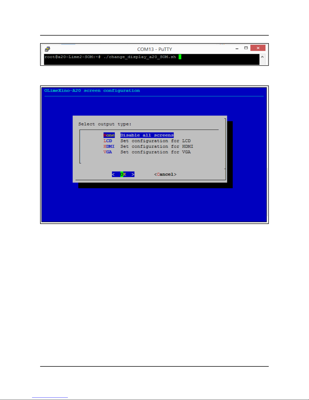
For Linux Debian you would need to execute a shell script to be able to change the resolution. It is
very good idea to use a serial cable for connection to the board from a personal computer since in
this case you are not dependent on the current video output resolution (a cable like USB-SERIALCABLE-F). When the board boots type:
./change_display*
or
./change_display_a20_SOM.sh
It looks like this:
Page 12 of 41
OLIMEX© 2015 A20-SOM user's manual
Then the main menu of the video configuration script shows up:
Choose the resolution and the interface (LCD, HDMI or VGA).
The supported resolutions are listed on the next page.
For LCD:
1. 4.3" (480×272)
2. 7" (800×480)
3. 10" (1024×600)
For HDMI:
0. 480i
1. 576i
2. 480p
3. 576p
4. 720p50
5. 720p60
6. 1080i50
7. 1080i60
Page 13 of 41
 Loading...