

Page 1
CrossFireTM 8730
Fast Ethernet
Translation Switch
DOC-7047/1.1
Reference Guide
Page 2

Page 3

CrossFireTM 8730
Fast Ethernet Translation Switch
Reference Guide
Page 4

ii
Trademarks
GoCard and the Olicom cla s ped hands log o ar e registered trademarks of Olicom A/S. Ce ll D river,
ClearServer, ClearSession, ClearSight, CrossFire, LANscout, PowerMACH, RapidFire and RapidLAN
are trad emarks of Ol icom A/S. ClearCare, C learPartn er , ClearStep and ExpertWatch are s ervice marks
of Olicom A /S. Olicom is a registered trademark. Oth e r brand and product names are trademarks,
register ed trademarks, service marks or registered service marks of their respect ive holders.
Copyrights
Olicom A/S reserves the rig ht to modify t he informa ti on given in t his publication wit hout pri or notice.
The war ranty te rms and conditions applicable fo r your purchase of this equipment are given at t he time
of purchas e. Please cons ult your place of purchas e for detail s .
Publi cation: DO C-7047 v. 1.1
© Copyright Olicom A/S,
All rights reserved
transmitted in any form or by any means, without the prior written permission of the publisher.
. No part of this publication may be r eproduce d, stored in a ret rieval system, or
Denmark, March 1999
FCC Compliance
This equipment has been tested and found to comply with the limits for a Class A digital device, pursuant
to Part 15 of the FC C Rul es. Thes e limi ts a re desi gned t o pro vide r easonab le protect ion ag ai nst har mful
interference when the equipment is operated in a commercial environment. This equipment generates,
uses and can radiate rad io frequency energy and, if not inst alle d and used in accordance with the
instruct ion manual, may cause harmf ul interfe rence to radio communications. Operation of this
equipmen t i n a r es idential ar ea is likely to cause harmful interference in which case the user w ill be
required to correct the interfe rence at his own expense.
Warning:
interfer ence in which case the user may be requi red to take adequate measures.
This device complies with part 15 of the FCC Rules. Operation is subject to the following two
condit ions: (1) This device may not cause harmful interfere nce, and (2) this device must accept any
interfe r ence received, including interference that may caus e undesired operation.
This is a Class A product. In a domestic environment this product may cause radio
Declaration of Conformity
We Olicom A /S
Nybrovej 114
DK-280 0 Lyngby
Denmark
declar e under our sole responsibility that the product
CrossFi re 8730 Fast Ethernet Tr anslat ion Switch
to which this declaration relates are in conformity with the following standards or other normative
documents
EN 50082-1
EN 55022
EN 60950 including Amendments
EN 60825-1
following the pro visions of 89/336/EEC D irective and 73/23/EEC Directive.
CrossFire 8730 Switch Reference Guide, DOC-7047 v. 1.1
Page 5

iii
Modifications
If the device i s changed or modifi ed w ithout the express approval of Olicom A/S the user may void his
or her authority to operate the equipment.
Safety N otic e s
➽
➽
➽
➽
Danger:
maint enance, or reconfiguring of the Cross Fire 8730 Fast Ethernet Translation Switch during an
electrical storm.
Danger:
the outlet before detaching the pow er cord from the CrossFire 8730 Fast Ethernet Trans lation Swi tch.
Danger:
Danger:
recept acle. Any equipment to which the CrossF ire 8730 Fast Ethernet Translation Swi tch will be
attach ed must also be connected to pr operly wired and earthed receptacles.
To avoid sho ck hazard, do not connect or di s connect any cables or perfor m installa tion,
To avoid the possibility of electrical shock, switch power off and unplug the power cord from
Do not open the CrossFire 8730 Fas t Ethernet Translat ion Switch. Dangerous voltages inside.
To avoid sho ck hazard the power cord must be connected to a properly wired a nd ear thed
Caution:
Obser ve the following power cable considerations before you begin instal lation of the CrossFire 8730
Fast Ethernet Translation Switch.
1. The socket outlet shal l be installed near the equipment and shall be easily accessible.
2. To prevent electrical shock, the power cord set used must comply with national regulations.
2a. The female receptacle of th e cord must meet CEE- 22 r equirements .
2b. The cord must be UL liste d, CSA lab elle d , and cons ist of thre e condu cto rs with a maxi mum
of 15 fee t i n length.
Type SVT or SJ T cord sets s hall be used for units which stand on a desk or table. T ype SJT
cord sets shall be us ed f or units which stand on floor.
➽
➽
2c. The male plug for units operating at 115 VA C shall consi s t of a parallel bl ade, grounding
type attachment plug rated 15 A, 125 VAC.
The male plug for units op erating at 230 VA C s hall consist of a tandem blade , grounding
type attachment plug rated 15 A, 250 VAC.
The male plug for units op erating at 230 VA C (outside of the United States and Canada) s hall
consis t of a grounding type attachment plug r a ted 15 A, 250 VAC and have the ap propriate
safety approvals for the country in w hich the equi pment will be installed.
Caution:
to avoi d dropping i t on the floor or any equipment beneath i t in the rack. T he C rossFire 8730 Fast
Ethernet Translation Swit ch unit weighs approximately 9. 5 kg ( 20.9 lbs).
Warning:
loca l area ne t w o r king (L A N ) .
Support the CrossFire 8730 Fast Ethernet Translation Switch while you are installing the unit
All RJ45 connectors must only be connected to safety extra low voltage (SELV) circuits like
CrossFire 8 730 Switch Ref erenc e Guide, DOC-7047 v. 1.1
Page 6

iv
CrossFire 8730 Switch Reference Guide, DOC-7047 v. 1.1
Page 7

Table of Contents
1. Introduction 1
About the CrossFire 8730 . . . . . . . . . . . . . . . . . . . . . 1
Translation from Token-Ring to Fast Ethernet . . . . . . . . . . . 2
Isolated Ethernet Segments or Servers . . . . . . . . . . . . 2
Application Example . . . . . . . . . . . . . . . . . . . . . . 3
Benefits of the CrossFire 8730 . . . . . . . . . . . . . . . . . . . 4
2. Switch Overview 15
How the CrossFire 8730 Works . . . . . . . . . . . . . . . . . 15
Multiple Simultaneous Conversati ons . . . . . . . . . . . . 15
Address Management . . . . . . . . . . . . . . . . . . . . 17
Multiple Bridging Modes . . . . . . . . . . . . . . . . . . . 17
Filtering. . . . . . . . . . . . . . . . . . . . . . . . . . . . 20
Congestion Control. . . . . . . . . . . . . . . . . . . . . . 20
Three Switching Modes . . . . . . . . . . . . . . . . . . . 21
Fast Ethernet. . . . . . . . . . . . . . . . . . . . . . . . . . . 2 2
Fast Ethernet Ports. . . . . . . . . . . . . . . . . . . . . . 2 2
Fast Ethernet Port Operation Modes. . . . . . . . . . . . . 23
Fast Ethernet Bridging Modes . . . . . . . . . . . . . . . . 23
Redundant Connections to Fast Ethernet Network . . . . . 25
Network Scenarios—Preventing Frame Duplication and
Looping. . . . . . . . . . . . . . . . . . . . . . . . . . . . 26
Spanning Tree Configuration for Fast Ethernet . . . . . . . 28
Technical Background . . . . . . . . . . . . . . . . . . . . 3 0
Token-Ring . . . . . . . . . . . . . . . . . . . . . . . . . . . . 32
Token-Ring Port Operation Modes. . . . . . . . . . . . . . 3 2
RI/RO-Like Connection . . . . . . . . . . . . . . . . . . . . 32
Transmission Priority Queues . . . . . . . . . . . . . . . . 3 3
CrossLink Connections. . . . . . . . . . . . . . . . . . . . 33
Spanning Tree Protocol Support . . . . . . . . . . . . . . . . . 34
VLAN Support . . . . . . . . . . . . . . . . . . . . . . . . . . 3 5
Management . . . . . . . . . . . . . . . . . . . . . . . . . . . 37
SNMP . . . . . . . . . . . . . . . . . . . . . . . . . . . . 37
Switch Manager for HP OpenView for Windows . . . . . . . 38
IBM LAN Network Manager . . . . . . . . . . . . . . . . . 38
RMON Support . . . . . . . . . . . . . . . . . . . . . . . . . . 39
Built-in Port Counters. . . . . . . . . . . . . . . . . . . . . . . 40
Stackable Architecture . . . . . . . . . . . . . . . . . . . . . . 40
Optional Redundant Power Supply. . . . . . . . . . . . . . . . 40
v
CrossFire 8 730 Switch Ref erenc e Guide, DOC-7047 v. 1.1
Page 8

vi
3. Switch Configura tion 41
General Guidelines . . . . . . . . . . . . . . . . . . . . . . . .42
Navigating within the Menus. . . . . . . . . . . . . . . . . .43
Main Menu. . . . . . . . . . . . . . . . . . . . . . . . . . . . .44
Configuration... . . . . . . . . . . . . . . . . . . . . . . . .44
Statistics.... . . . . . . . . . . . . . . . . . . . . . . . . . .44
Download/Upload... . . . . . . . . . . . . . . . . . . . . . .44
Reset... . . . . . . . . . . . . . . . . . . . . . . . . . . . .44
Exit Console . . . . . . . . . . . . . . . . . . . . . . . . . .44
Configuration Menu . . . . . . . . . . . . . . . . . . . . . . . .45
Configuration Overview for the Fast Ethernet Ports. . . . . .45
Switch Configuration Screen. . . . . . . . . . . . . . . . . . . .46
Stack Configuration Screen . . . . . . . . . . . . . . . . . .49
Module Information Screen . . . . . . . . . . . . . . . . . .50
VLAN Configuration . . . . . . . . . . . . . . . . . . . . . . . .52
VLAN Configuration Menu. . . . . . . . . . . . . . . . . . .53
VLAN Configuration Screen . . . . . . . . . . . . . . . . . .54
VLAN Parameter Configuration for TrCRF Screen . . . . . . 55
VLAN Par a met e r Configura tion fo r T r BRF S cree n . . . . . .57
Local VLAN Port Configuration Screen . . . . . . . . . . . .59
IP Configuration Screen . . . . . . . . . . . . . . . . . . . . . .60
BootP Requests and Parameters . . . . . . . . . . . . . . .62
SNMP Configuration Menu . . . . . . . . . . . . . . . . . . . .63
Spanning Tree Protocol . . . . . . . . . . . . . . . . . . . . . .64
IEEE 802.1D Spanning Tree Proto col (STP) . . . . . . . . .64
Spanning Tree for TrBRF Screen . . . . . . . . . . . . . . .65
Spanning Tree for TrCRF Screen . . . . . . . . . . . . . . .67
Port Spanning Tree Parameters Screen. . . . . . . . . . . .70
Current Spanning Tree Information Screen . . . . . . . . . .71
Port Configuration Screen . . . . . . . . . . . . . . . . . . . . .72
Token-Ring Port Configuration . . . . . . . . . . . . . . . .72
Fast Ethernet Port Configuration . . . . . . . . . . . . . . .76
Virtual Port Configuration . . . . . . . . . . . . . . . . . . . . .78
Virtual Port Configuration Screen . . . . . . . . . . . . . . .78
Frame Conversion Configuration . . . . . . . . . . . . . . . . .81
Frame Conversion Configuration Screen . . . . . . . . . . .81
IP Frames Conversion Screen. . . . . . . . . . . . . . . . .83
Novell Conversion Configuration Screen . . . . . . . . . . .85
NetBios Conversion Configuration Screen . . . . . . . . . .87
SNA Conversion Configuration Screen . . . . . . . . . . . .89
Other w SNAP Conversion Configuration Screen . . . . . . .91
Other w/o SNAP Conversion Configuration Screen . . . . . .93
Dual Home FEP Addresses Configuration Screen . . . . . .95
CrossFire 8730 Switch Reference Guide, DOC-7047 v. 1.1
Page 9

vii
Switched Port Analyzer Menu . . . . . . . . . . . . . . . . . . 96
CrossLink. . . . . . . . . . . . . . . . . . . . . . . . . . . . . 97
CrossLink Menu . . . . . . . . . . . . . . . . . . . . . . . 9 8
CrossLink Configuration Screen . . . . . . . . . . . . . . . 99
Setting up a CrossLink . . . . . . . . . . . . . . . . . . . .10 0
Current CrossLink Information Screen . . . . . . . . . . . .101
Address Filtering . . . . . . . . . . . . . . . . . . . . . . . . .102
Filters and Port Security Menu . . . . . . . . . . . . . . . .103
Configure Filters Screen . . . . . . . . . . . . . . . . . . .104
Configure Port Security Mode Screen . . . . . . . . . . . .106
View Port Filters Screen . . . . . . . . . . . . . . . . . . .10 7
Protocol Filters Menu. . . . . . . . . . . . . . . . . . . . .108
Protocol Class Assignment Screen . . . . . . . . . . . . .109
Port Filtering Attributes Screen. . . . . . . . . . . . . . . .110
Address Aging . . . . . . . . . . . . . . . . . . . . . . . . . . 112
Address Aging Menu . . . . . . . . . . . . . . . . . . . .113
Port Address Table Aging Screen . . . . . . . . . . . . . .114
Master Address Table Aging Screen. . . . . . . . . . . . .115
Password Menu . . . . . . . . . . . . . . . . . . . . . . . . .116
Console/Telnet Sessions. . . . . . . . . . . . . . . . . . . . .117
Console Configuration Menu. . . . . . . . . . . . . . . . .117
Serial Link Configuration Screen. . . . . . . . . . . . . . .118
Creating a Console Session Using a Modem . . . . . . . .119
Stopping the Console Session . . . . . . . . . . . . . . . .119
Telnet Configuration Screen . . . . . . . . . . . . . . . . .120
Telnet Sessions Screen . . . . . . . . . . . . . . . . . . .121
Starting the Telnet Session. . . . . . . . . . . . . . . . . .122
Stopping the Telnet Session . . . . . . . . . . . . . . . . .122
Involuntary Termination of the Telnet Session . . . . . . . .122
Syslog Daemon Screen . . . . . . . . . . . . . . . . . . . . . 124
Download/Upload Menu . . . . . . . . . . . . . . . . . . . . .12 5
Serial Link Download Screen. . . . . . . . . . . . . . . . .126
TFTP . . . . . . . . . . . . . . . . . . . . . . . . . . . . .127
TFTP Download/Upload Screen . . . . . . . . . . . . . . .127
Reset Screen. . . . . . . . . . . . . . . . . . . . . . . . . . .130
4. Monitoring the Network from the Statistics Menu 133
Statistics Menu . . . . . . . . . . . . . . . . . . . . . . . . . .134
Switch Statistics Screen . . . . . . . . . . . . . . . . . . .135
Power Supply Information Screen . . . . . . . . . . . . . .13 7
Port Status Screen . . . . . . . . . . . . . . . . . . . . . .138
Port Statistics Menu for Token-Ring Ports . . . . . . . . . .140
Port Stati s tics Menu fo r Fas t Ether n e t Port s . . . . . . . . .141
CrossFire 8 730 Switch Ref erenc e Guide, DOC-7047 v. 1.1
Page 10

viii
General Statistics Screen for Token-Ring Ports. . . . . . . 142
General Statistics Screen for Fast Ethernet Ports. . . . . . 145
Discarded Frames Screen. . . . . . . . . . . . . . . . . . 147
Discarded Inbound Frames . . . . . . . . . . . . . . . . . 147
Discarded Outbound Fram es . . . . . . . . . . . . . . . . 148
802.5 Statistics Screen . . . . . . . . . . . . . . . . . . . 149
802.5 State Information Screen . . . . . . . . . . . . . . . 152
802.5 DTR MAC Information Menu . . . . . . . . . . . . . 154
TXI Information Screen . . . . . . . . . . . . . . . . . . . 155
Station-CPort Information Screen . . . . . . . . . . . . . . 157
802.3 Statistics Screen . . . . . . . . . . . . . . . . . . . 158
Virtual Port Statistics Screen . . . . . . . . . . . . . . . . 161
Discarded Frames Statistics. . . . . . . . . . . . . . . . . 162
Inbound Discarded Frames Statistics - No Translation . . . 162
Inbound Discarded Frame Statistics - Translation Errors . . 163
Outbound Discarded Frame Statistics - No Translation . . . 163
Outbound Discarded Frame Statistics - Translation Errors . 164
Address Tables Menu . . . . . . . . . . . . . . . . . . . . 165
Master Address Table Screen. . . . . . . . . . . . . . . . 166
Master Route Descriptor Table Screen . . . . . . . . . . . 168
VLAN Address Table screen . . . . . . . . . . . . . . . . 170
VLAN Route Descriptor Table Screen. . . . . . . . . . . . 171
Locate MAC Address Screen . . . . . . . . . . . . . . . . 172
Current Spanning Tree Information Screen . . . . . . . . . 173
Current Spanning Tree Information for a TrCRF Screen . . 176
VLAN Statistics Screen for TrCRF. . . . . . . . . . . . . . 179
VLAN Statistics Screen for TrBRF. . . . . . . . . . . . . . 180
Diagnostic Test Results Screen . . . . . . . . . . . . . . . 181
Message Log Information Screen . . . . . . . . . . . . . . 182
Display Summary Screen . . . . . . . . . . . . . . . . . . 183
5. Monitor ing the Network with S NMP 185
SNMP Setup. . . . . . . . . . . . . . . . . . . . . . . . . . . 185
IP Configuration Screen . . . . . . . . . . . . . . . . . . . . . 185
SNMP Configuration. . . . . . . . . . . . . . . . . . . . . . . 186
SNMP Configuration Screen. . . . . . . . . . . . . . . . . 186
Community Strings Screen . . . . . . . . . . . . . . . . . 187
Trap Receivers Screen . . . . . . . . . . . . . . . . . . . 189
List of Supported Traps from a Switch. . . . . . . . . . . . 190
6. Monitoring Port Traffic 195
Switched Port Analyzer Screen . . . . . . . . . . . . . . . . . 196
CrossFire 8730 Switch Reference Guide, DOC-7047 v. 1.1
Page 11

ix
7. Getting in Touch with Technical Support 197
Before You Contact Olicom Technical Support . . . . . . . . . 197
Hotline Support. . . . . . . . . . . . . . . . . . . . . . . . . .19 7
Fax Support . . . . . . . . . . . . . . . . . . . . . . . . . . .198
Internet E-Mail . . . . . . . . . . . . . . . . . . . . . . . . . .198
Anonymous Internet FTP Server. . . . . . . . . . . . . . . . .198
Internet World Wide Web Server (WWW) . . . . . . . . . . . .198
Olicom Support WEB. . . . . . . . . . . . . . . . . . . . . . .199
Problem Report Form . . . . . . . . . . . . . . . . . . . . . .200
Appendix A. Abbreviations 203
CrossFire 8 730 Switch Ref erenc e Guide, DOC-7047 v. 1.1
Page 12

x
List of Figures
Figure 1. CrossFire 8730 Fast Ethernet Translation Switch . . . . . 1
Figure 2. Translation Strategy: Fast Ethernet Ports Operating as 400
Mbps CRF. . . . . . . . . . . . . . . . . . . . . . . . . . 2
Figure 3. Integrating Ethernet and Token-Ring Networks Using a
CrossFire 8730 . . . . . . . . . . . . . . . . . . . . . . . 3
Figure 4. Multiple Conversations Through a CrossFire 8730 . . . . . 16
Figure 5. Typical Configuration with Switches Using Multiple Bridging
Modes. . . . . . . . . . . . . . . . . . . . . . . . . . . . 17
Figure 6. Source Route Transparent Bridging (SRT) Mode. . . . . . 24
Figure 7. Source Route Bridging (SRB) Mode . . . . . . . . . . . . 25
Figure 8. Preventing Frame Duplication . . . . . . . . . . . . . . . 26
Figure 9. Frame Looping . . . . . . . . . . . . . . . . . . . . . . . 27
Figure 10. Preventing Frame Looping . . . . . . . . . . . . . . . . . 28
Figure 11. S pannin g Tree Configuration . . . . . . . . . . . . . . . . 29
Figure 12. Two Separat e Ethernet Clouds . . . . . . . . . . . . . . . 30
Figure 13. STP BPDU Cost Modification. . . . . . . . . . . . . . . . 31
Figure 14. A Switch Configured with Two VLANs . . . . . . . . . . . 36
Figure 15. Switch with Four VLANs . . . . . . . . . . . . . . . . . . 52
Figure 16. Setting up CrossLinks for Token-Ring Ports . . . . . . . . 97
List of Tables
Table 1. Translational Switching Benefits . . . . . . . . . . . . . . 4
Table 2. Benefits of the Multiple Bridging Modes . . . . . . . . . . 5
Table 3. Benefits of Token-Ring Port Operation Modes . . . . . . . 6
Table 4. Benefit of Ethernet Port Operation Modes . . . . . . . . . 7
Table 5. Benefits of the Switching Modes . . . . . . . . . . . . . . 8
Table 6. Spanning Tree Protocol Benefits . . . . . . . . . . . . . . 9
Table 7. Management Bene fits. . . . . . . . . . . . . . . . . . . . 10
Table 8. Network Monitoring Benefits . . . . . . . . . . . . . . . . 11
Table 9. Filtering Benefits . . . . . . . . . . . . . . . . . . . . . . 12
Table 10. Connectivity Benefits . . . . . . . . . . . . . . . . . . . . 13
Table 11. Supported MIBs. . . . . . . . . . . . . . . . . . . . . . . 37
Table 12. Modem Settings. . . . . . . . . . . . . . . . . . . . . . 119
CrossFire 8730 Switch Reference Guide, DOC-7047 v. 1.1
Page 13

About this Guide
This reference guide contains in f o rmation needed to o per ate th e CrossFireTM 8730
Fast Ethernet Translation Switch. The user of this guide is assumed to be a network
technician familiar with the installation and operation of networking equipment.
In addition to this reference guide, the CrossFire 8730 Switch is delivered with the
CrossFire 8730 Fast Ethernet Translation Switch Installation Guide
as a printed manual and as a pdf file in the package. The installation guide contains
information needed to install and get started with the switch.
This reference guide contains the following chapters:
xi
enclosed both
Chapter 1, “Introduction”
and lists features and benefits of the switch.
Chapter 2, “Switch Overview”
network performance and describes the various features supported on the switch.
Chapter 3, “Switch Configuration”
switch using a direct console connection.
Chapter 4, “Monitoring the Network from the Statistics Menu”
to monitor the switch using the
Chapter 5, “Monitoring the Network with SNMP”
switch from a Network Management System using an application that supports
Simple Network Management Protocol.
Chapter 6, “Monitoring Port Traffic”
switch using SwitchProbe.
Chapter 7, “Getting in Touch with Technical Support”
services such as hotline support, fax support and the support web, as well as other
services such as bulletin board service, FTP server and e-mail.
, discusses translation from Token-Ring to Ethernet
, gives an overview of how the switch improves
, deals with setting up and configuring the
, explains how
Statistics
menu through a direct console connection.
, explains how to monitor the
, explains how to monitor ports on the
, lists Olicom’s support
Appendix A, “Abbreviations”
Document Conventions
The following conventions are used in this guide:
•
HELVETICA NARROW
“Press
•
Items displayed on the screen, such as menus and parameters, are indicated
with bold. For example, “Select
CrossFire 8730 Switch Reference Guide, DOC-7047 v. 1.1
ENTER
, lists the abbreviations used in this manual.
indicates keystrokes, as in
to select the item.”
Configuration...
in the main menu.”
❏
Page 14

xii
CrossFire 8730 Switch Reference Guide, DOC-7047 v. 1.1
Page 15
1.Introduction
This chapter discusses translation fromToken-Ring to Ethernet on a general level
and lists important features and benefits of the CrossFire 8730 Switch.
For information on the specific physical features of the switch, please refer to the
CrossFire 8730 Fast Ethernet Translation Switch Installation Guide.
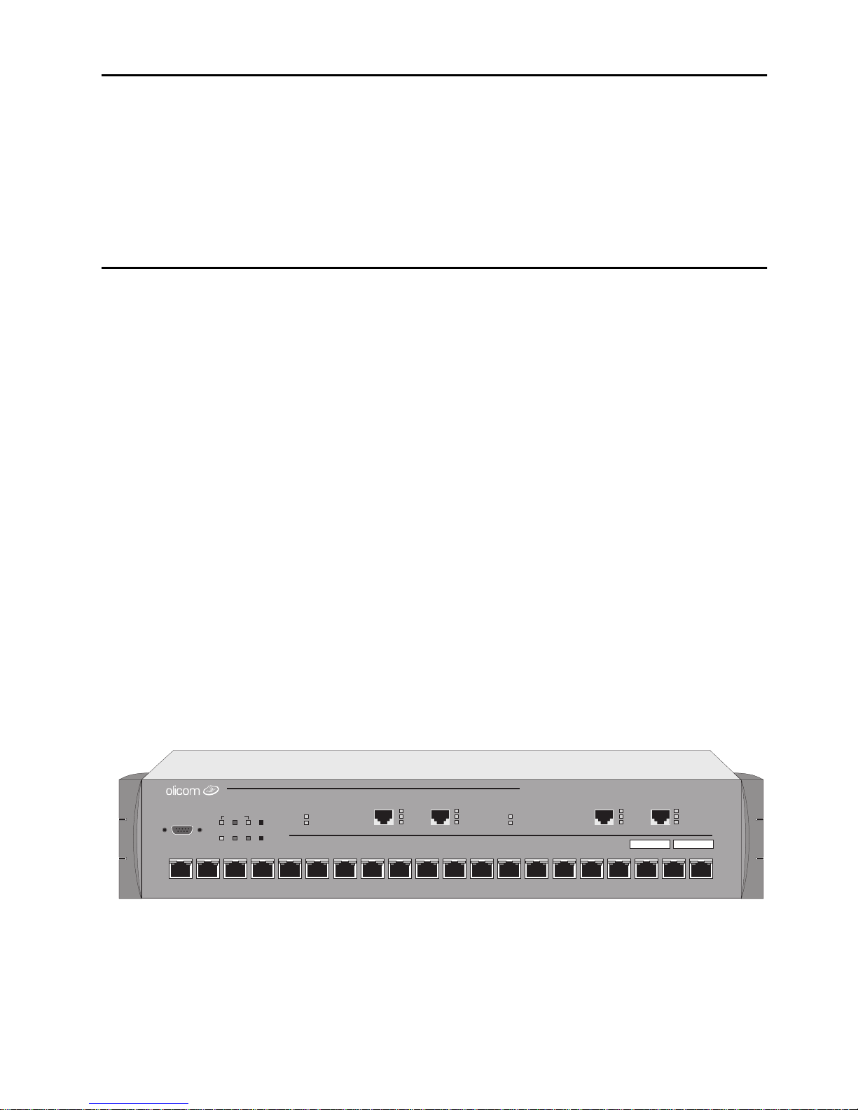
About the CrossFire 8730
The CrossFire 8730 is a simple and inexpensive solution to the challenge of
connecting Token-Ring and Ethernet networks, enabling data to quickly and easily
flow between the two architectures - at nearly wire speed.
The CrossFire 8730 translates all Token-Ring packets directly into Fast Ethernet
frames. This avoids the limitations of proprietary encapsulation techniques.
1
The CrossFire 8730 supports translational bridging for the key network protocols
SNA, IP, IPX, and NetBios. Moreover, all native Token-Ring features, including
source routing and IEEE 802.1Q tagged VLAN are supported as well as all network
speeds for both standard Token-Ring (16/4 Mbps) and Ethernet (10/100 Mbps).
Also, the CrossFire 8730 supports four different switching modes to provide
maximum flexibility in all installation environments. The switching modes are
Source Route Switching (SRS), Source Route Bridging (SRB), Source Route
Transparent (SRT) and SRT/SRB.
For more infor matio n o n these features read
Chapter 2, “Switch Overview”
.
CrossFire8730
STACK-LINK
ATTACH
RXTX
DIAGPWR RSTERRMANAGEMENT
1
32 54
STATUS
FAULT
21-22 25-2622 2625
ACT
100
LINK
21
876109
ACT
100
LINK
STATUS
FAULT
FASTETHERNET
151211 1413 1716 1918 20
FastEthernetTranslationSwitch
ACT
100
LINK
ACT
100
LINK
Figure 1. CrossFire 8730 Fas t Ethe rnet T ranslation Switch
CrossFire 8730 Switch Reference Guide, DOC-7047 v. 1.1 Introduction
Page 16
2
Translation from Token-Ring to Fast Ethernet
The configur ation options of the CrossFire 8730 Switc h pr ovide for several
translation strategies, thereby providing extra flexibility for managers when
designing their integrated network. The best option will depend on the cu rrent
network and the migration strategy.
This section describes a typical migration strategy and gives an example of an
application of the CrossFire 8730.
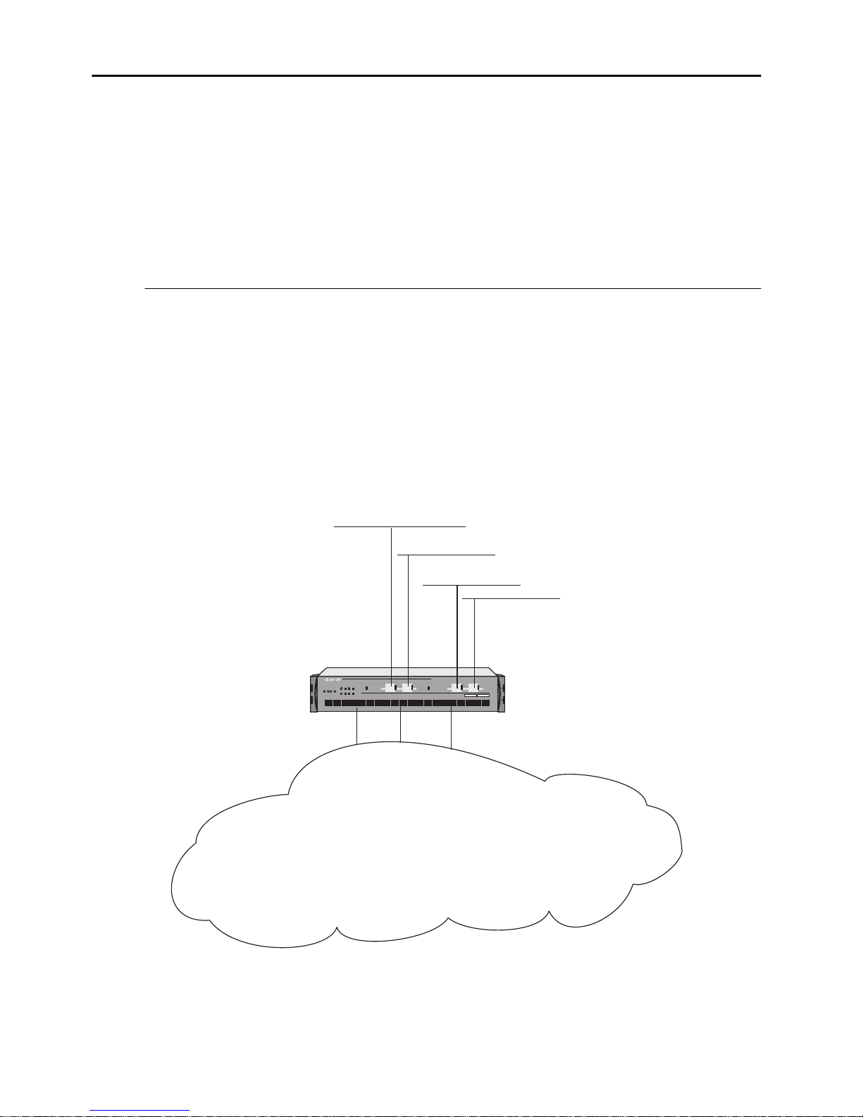
Isolated Ethernet Segments or Servers
As the sta rting p oint for mig rat ing a br idge d Toke n-Ring ne twork to Fast Ethe rnet,
the switch could be set up with the four Fast Et hernet ports conn ec ted to four
isolated E thernet segments or Fast Ethernet Attached servers. The CrossFire 8730
Switch will mak e servers and workstations attache d to the Fast Ether n et ports
appear to be on a single logical Ethernet segment connected to the Toke n-Ring
network through the switch. This configuration will provide a translation
bandwidth corresponding to that of four Fast Ethernet ports.
STACK-LINK
ATTACH
RXTX
DIAGPWR RSTERRMANAGEMENT
3254
1
STATUS
FAULT
21-22 25-2622 2625
ACT
100
100
LINK
LINK
21
FASTETHERNET
876109
STATUS
FAULT
151211 1413 17161918 20
ACT
ACT
100
100
LINK
LINK
FastEthernet Translation Switch
CrossFire8730
ACT
Token-Ring cloud
Figure 2. Translation Strategy: Fast Ethernet Ports Operating as 400 Mbps
CRF
CrossFire 8730 Switch Reference Guide, DOC-7047 v. 1.1 Introduction
Page 17
Application Example
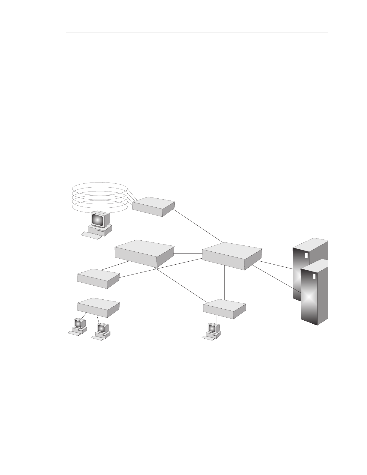
The CrossFire 8730 Fast Ethernet Translation Switch is ideal for sit uations in
which the plan is to connect To ken-Ring cli ents to a Fast Ethernet backbone. It
provid es switched Token-Ring ports for legacy users and Fast Ethernet ports to
connect to a new Fast Etherne t backbone. Tr anslation be tween Etherne t and TokenRing is perf ormed within the Cross F ire 8730 Switch, making the migration
seamless.
The Fast Ethernet backbone can be forme d usi ng se veral CrossFir e 8720 Fast
Ethernet Ba ckbone Switches or the CrossFi re 8710 Fast Ethernet Stackabl e Switch.
This provides a high-performance Eth erne t backbone, adds Layer 3 and Layer 4
capabi lities to the Ethernet network, and introduces the possibi lities of integrat ing
ATM and Gigabit Et hernet.
3
CrossFire 8730 Fast Ethernet Translation Switch
CrossFire 8720 Fast Ethernet
Backbone Switch
CrossFire 8711 Fast Ethernet
Workgroup Switch
RapidLan 2800
Fast Ethernet Hub
CrossFire 8710 Fast Ethernet
Stackable Switch
RF2410
CrossFire 8710 Fast Ethernet
Stackable Switch
Figure 3. Integrating Ethernet and Token-Ring Networks Using a
CrossFir e 8730
CrossFire 8730 Switch Reference Guide, DOC-7047 v. 1.1 Introduction
Page 18

4
Benefits of the CrossFire 8730
This section looks into the benefits that can be deri ved from the technical featur es
of the switch.
Translational Switching
Feature Description Benefit
High-speed
translation between
Fast Ethernet and
Token-Ring
Next-generatio n
switch architecture
IEEE 802.1Q
tagged VLAN
support over the
Fast Ethernet li n k
Support for IP
multicasting
Translates frames
between Token-Ring
and Fast Et hernet at
nearly line spe ed
Full-featured
switching for
maximum
performance and
compatibility
Industry standard
that enables fram es
belonging to
diff erent VLANsto
be carried over the
same physical link
Transmissions from
a single source ca n
be delivered to
se veral subscribing
participants .
Fast and efficie nt integr ation of
Token-Ring and Fast Ethernet
networks
Segment legacy LAN to
improve performance until
migration is complete.
Translation to Fast Ethernet
Avoids unnecessary
broadcasting to provide an
efficient use of bandwidth.
Support for IP
fragmentation
NetBios Address
Translation
Table 1. Translational Switching Benefits
CrossFire 8730 Switch Reference Guide, DOC-7047 v. 1.1 Introduction
Provides tight
compatibility with
IP-based networks
Provides tight
compatibility for
networks using
NetBios
Ensures fast, simple
connections between IP,
Token-Ring and Ethernet
networks
Ensures fast, efficient
performance
Page 19

Multiple Bridging Modes
Feature Function Benefit
5
Transparent
and Source Route
Swit c h ing (S R S )
Source Route
Bridging (SRB)
Switchi ng is based on
MAC addresses only.
Learns MAC
addresses and source
routing route
descriptors of So urce
Route Bridge s
attached to local
switch port s.
The switch ports may
be grouped into logical
rings. The switch acts
as a standar d
multiport Source
Route Bridg e between
logical ri ngs. Non
Source Route frames
(NSR) are not
forwarded outside the
logical ring.
Allows easy ins tallati on in
environments with no need for
Source Route Bridging.
Allows easy ins tallati on in
exis ting Token-Ring networks
where S our ce Rout e Bridg es are
used. Al low s ea s y replacem en t
of bridges with switches.
Source Route
Transparent
Bridging (SRT)
NSR frames are
forwarded betw ee n
Logical Rings based
Allows the mix of source route
and non source rout e protocols
in the n et wo r k.
on MAC address.
Source Route frames
are for w ard ed as by
SRB.
SRT/SRB
Combines the SRT
and SRB modes.
Allows the use of duplicate
MA C addresses when running in
SRT. Ports with duplicate MAC
addresses are reachable only via
source routing. Duplicate MAC
addresses are typically found in
installations utilizing SNA
gate ways and/or front-ends.
Table 2. Benefi ts of the Multiple Bridging Modes
CrossFire 8730 Switch Reference Guide, DOC-7047 v. 1.1 Introduction
Page 20

6
Token-Ring Port Operation Modes
Each port can be independently configured to one of the fol lowing operating
modes.
Feature Function Benefit
Half-duplex
concentrator port
Half-duplex station
emulation
Full-duplex
concentrator port
Full-duplex station
emulation.
Port behaves lik e an
active MAU po rt fo r
classical T o k en-Ring.
The Token-Ring port
is c onnected to a p ort
on a M AU.
Connects to a single
station in full-duplex.
Connect s to another
switch in full-duplex
mode.
Connects to a s ingle station in
half-duple x mode . Compatibl e
with ol d er ad ap t er s .
Connects to classical TokenRing segments with multiple
stations in existing
installations.
Allows high-performance
station and server connection
and allows high performance
server attachments with up to
97% improvement over a hal f duplex Token-Ring
connection.
Allows easy connection
between switc hes.
RI/RO-like
connection
on Token-Ri ng ports
19 and 20
Allows connection
of the RI/RO p or t
from a MA U or CAU
directly to th e
Enables easy integration into
exis ti n g in s t allat io n s .
switch.
Automatic port
sensing of operating
mode
Au to-c onfiguration
The port senses
automatically which
mode to operate in.
All Token-Ring and
Makes ins tallation easier and
faster.
Easy, plu g and play in stal lati on
Ethernet switch ports
automatically sense
connection speed
and duple x mode.
Table 3. Benefits of Token-Ri ng Port Operation Mod es
CrossFire 8730 Switch Reference Guide, DOC-7047 v. 1.1 Introduction
Page 21

Feature Function Benefi t
7
Congestion control
The size of each
port’s output queue
Minim i ze s the effect of
congestion on output ports
is monitore d. I n case
of congestion the
queue size is
adjusted through
frame priority
adjustmen t an d
frame purging.
Table 3. Benefits of Token-Ring Port Operation Modes
Fast Ethernet Port Operation Modes
Each port can be independently configured to one of the following operating
modes:
Feature Function Benefit
Half-duplex
10 Mbps
Half-duplex 100
Mbps
Full-duplex
10 Mbps
Full-duplex 100
Mbps
Switch-to-switch,
switch-toworkstation or
switch-to-HUB
connection.
Switch-to-switch,
switch-toworkstation or
switch-to-HUB
connection.
Switch-to-switch or
switch-toworkstation
connection.
Switch-to-switch or
switch-toworkstation
connection.
Compatibility with older
adapters in half-duplex mode.
Allows high performance
connection in half-dupl ex
mode.
Compatibility with older
adapters in full-duplex mode.
Allows high performance
server or switch connection in
full duplex mode.
Table 4. Benefi t of Ethernet Port Operati on Modes
CrossFire 8730 Switch Reference Guide, DOC-7047 v. 1.1 Introduction
Page 22

8
Three S wi t chin g M odes
Note th at th e Fas t Eth e r ne t p o rt s al w ay s us e th e
Feature Function Benefit
Cut-Through
for Token-Ring
.
Switches with
minimum and
constant latency,
app r ox ima tely 35 µs
Store an d Forward
for both Token-Ring
and Fast Ethernet.
Each packet is
forwarded only after
the ent ir e pac ket has
been re ce ived by th e
switch. Thi s is u s ed
for data transfer
between L A N
segments of different
speeds or for LAN
segments with a high
error rate.
Store and Forwar d
mode.
Lowest possible switch-latency,
which means optim al response
time for end-users.
Does not propagat e errors to
other segments.
Auto
(Adaptive
Cut-Through)
for Token-Ring.
Cut-through
switching that checks
for error packets . If a
port’s errors exceed a
user-defined threshold
then the port switches
to store and forwar d.
Table 5. Benefit s of the Switching Modes
Same speed as cut-through
switching, but with built-in
adaptation to errors which
means th at bandwidth is
effectively preserved
CrossFire 8730 Switch Reference Guide, DOC-7047 v. 1.1 Introduction
Page 23

Spanning Tree Protocol
Feature Function Benefit
9
IEEE 802.1D
Allows redundant
network paths to be
defined in both SRB and
transparent switching
configurations.
Enables Spanning Tree
to be implemented on
both Ethernet and
Token-Ring networks,
as well as IBM
Spanning Tree on the
Token-Ring side.
IBM
for Token-Ring
only.
When in SRB/SRT
mode, a combination of
IBM spanning tree a nd
IEEE 802.1D is used.
Table 6. Spanning Tree Protocol Benefits
No single point of failure. The
duplicate STP modes allow
operation in both transparent
and source route bridging
modes.
Easy compa tibil it y wi th
existing Ethernet and TokenRing installations
Same as above, and in addition
ensures compatibility in IBM
SRB installations.
CrossFire 8730 Switch Reference Guide, DOC-7047 v. 1.1 Introduction
Page 24

10
Management
Feature Function Benefit
SNMP
VLAN support
HP OpenView for
Windows
Additional Network
Management
applications available
for Unix platforms:
HP OpenView NNM
for HP- UX
and
T ivoli TME 10
NetView for AIX
Can be configured
and managed usi ng
SNMP management
stat ion.
Ensures the
av ai labil it y of a high
number of switched,
port based, VLANs
for an enterprise
network.
Full Graphical HP
OpenView for
Windows
management
application.
Allows integr ation into any
SNMP-based management
environment.
Eases network-wide
administration by enabling
ports to be grouped toge th er in
a logical way. Provid es
performance and security
control. Enables effective
broadcast control. Improves
and simplifies adds, moves,
and changes in th e net w ork.
Allows full graphical
integra tion into HP OpenView
management environments.
Telnet management
VT100
management
Table 7. Management Benefi ts
CrossFire 8730 Switch Reference Guide, DOC-7047 v. 1.1 Introduction
Allows management
from a any LAN
stat ion via Telnet.
Allows out-of-band
management from an
external VT100 type
terminal connected
directly or via a
modem.
Makes management flexible by
enabling managem ent from
any station.
Enables management of
switches in remote locations.
Page 25

Network Monitoring
Feature Function Benefit
11
RMON support
Passive Port
Monitoring
Active Port
Monitoring
Support for To kenRing spe cif i c r emote
mon itor i ng.
All traf fic flo wing on
the moni tored p ort is
copi ed to th e
monitoring port (the
monitoring port is a
true copy of the
monitored port).
All tr affic swi t c h ed
to and from the
monitored port is
also sent to the
monitoring port (the
order and timing of
frames on the
monitoring port can
be different).
Enab les collection and anal ysis
of enhanced tr affic-
management data.
Eases the m anagement tas k by
making it easy to collect
Toke n- R ing statis t i c s w ith a
special passive network
analyzer.
Eases the m anagement tas k by
making it easy to collect
network s tatis tics and c arry ou t
protocol analysis. Active
monitoring respects the MAC
protocol, allowing the use of a
standard net work analyzer.
Buil t -i n p o rt
counters
Many MAC layer,
erro r, an d frame
forwarding counters
are collect ed per port
Port Mirro ri n g
Allows any port to b e
used for connect ing a
network analyzer.
Can then duplicate
traffic n any other
por t to troubleshoo t
attach ed se g ments.
Table 8. Network Monitori ng Benefits
Provides a detailed picture of
port traffic.
Greatly simplifies system
management a nd f acilitat es
collec tion of net work stati stic s.
CrossFire 8730 Switch Reference Guide, DOC-7047 v. 1.1 Introduction
Page 26

12
Filtering
Feature Function Benefit
MAC address
Allows filtering
based on f r am e
source and
dest inati on MAC
addresses.
Logical Link
Control (LLC):
DSAP/SNAP
Allows filtering
based on LLC
parameters DSAP
(Destination Source
Acce ss Point) and
SNAP (Subnetwork
Access Protocol).
Table 9. Filte ri ng Be nefi ts
Preserves available network
bandwidth b y restrict ing traf fic
from propagating beyond the
needed lim i ts . E n ab le s
enhanced network security
policies to be establi shed.
Same as ab ov e.
CrossFire 8730 Switch Reference Guide, DOC-7047 v. 1.1 Introduction
Page 27

Connect ivit y Options
Feature Function Benefit
13
CrossLink highspeed in t e r-s w itch
connection for
Token-Ring (
up to
256 Mbps using
eight ports)
Stackable:
3 possibilities:
A. 2 switch stack
B. 5 switch stack
C. 8 switch stack
Optional
redundant power
supply
Allows switches to
be interconnected
usi ng 1- 8 TokenRi ng po rts.
Stack Products
Needed:
A. 2 x 8630
B. 1 x 8635 and
4 x 8630
C. 1 x 8300 and
8 x 8630
Up to six sw itches
can recei ve backup
power from one
CrossFire 8310
Redundant Power
supply, fully
equipped with six
CrossFire 8311
power sup ply units.
(Note that CrossFire
8311 is
not
hot-
swappable.)
Pro v ides easy and s calable
switch inter connection.
Allows sev eral switche s to be
stacked, accommodating
switch scalability up to 160
switched Token-Ring ports and
32 Fast Ethernet ports.
Gives a high degree of
resilience to power supply
failures when used in critical
applications.
Table 10. Connecti vity Benefits
CrossFire 8730 Switch Reference Guide, DOC-7047 v. 1.1 Introduction
❏
Page 28

14
CrossFire 8730 Switch Reference Guide, DOC-7047 v. 1.1 Introduction
Page 29

2. Switch Overview
This chapt er explains how the CrossFire 8730 Fast Etherne t Translation Switch
improve network performance.
How the CrossFire 8730 Works
The swit ch contains the f o llowing main elements, as listed below:
•
Switchin g Bus—the a rch itect ure of the swit ch cent ers a round the AXIS bus , a
520 Mbps switching fabric through which all switched ports communicate.
The AXIS bus is a partially asynchronous time divisi on multiplexed bus used
for switching packets between heterogeneous LAN modules.
•
Token-Ring Ports—e ac h port can attach to a classical Token-Ring s egment or
to a dedicated s tation. Now users running basic applicat ions are able to sha r e
bandwidth, and use r s r unning bandwidth -intensive applic ations can receive
their own dedicated 16 Mbps port. Ea ch dedicated port can also be s et up in
full-duplex communication mode, so that each 16 Mbps port doubles to 32
Mbps.
15
•
Fast Etherne t Ports— each port can attach to a 10/100 Mbps Fas t Et hernet
network or Fast Ethernet station.
•
Stack Link Module— the switc h support s a stac k lin k module that can be used
to connect two switches in a back-to-back configu r ation. Alternatively, up to
fiv e switc hes can be c onnected toge ther usi ng and inte rnal sta cker module , and
up to eight s witches can be connect ed togethe r using the sta ck link mod ule and
an additiona l switch stack unit. By connect ing switches together throug h the
stack link modu le, the switches virtually combine to form a single unit,
providing scalability, simplified mana gement, and enhanced performance.
Multiple Simultaneous Conversations
A limitation of a shared media LAN is that it supports only one packe t at a time.
The CrossFire 8730 improve data throughput by suppor ting multiple,
simultaneous, full-duplex conversations. By using High-Speed bus switching
technology, the switch creates multiple data paths. These switched connecti ons
between LAN segments last only for the duration of a byte transmi ssion. New
connections are made “on-the-fly” between di fferent ports on the switch for the
next byte.
CrossFire 8 730 Switch Ref erenc e Guide, DOC-7047 v. 1.1 Switch Overview
Page 30
16
Host B
Host A
CrossFire 8730
Switch
Host D
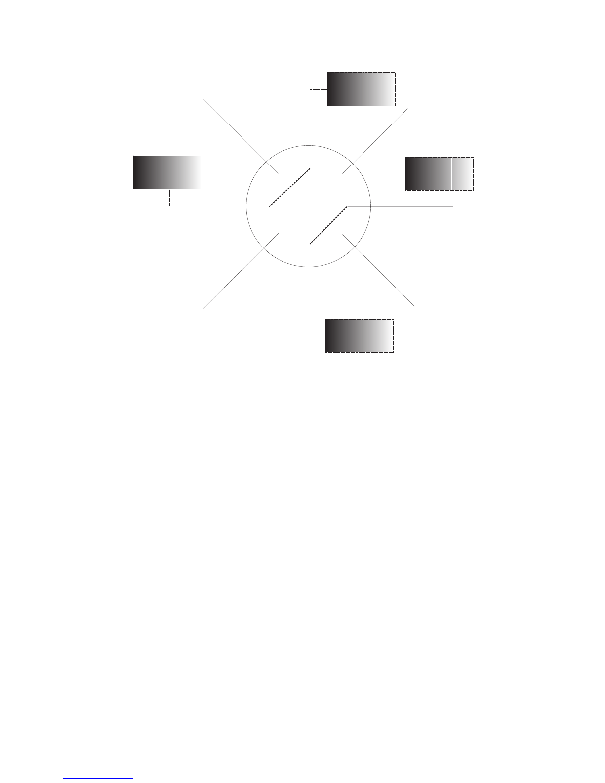
Figure 4. Multiple Conversations Through a CrossFire 8730
Host C
For example, as s hown in F igure 4, while host A is transmitting a byte to host B,
the swi tch connects only the line s from A to B since th ere is no need to send pac kets
to all other ports. At the same time, a second switc hing circuit can connect host C
to host D. The result: Two packets are sent simultaneously.
➽ Note:
The switc h transmits broad cast and mult icast pack ets on se veral swi tch ports
simult aneou sly.
The incr ease in throughput is directly propo rtional to the numbe r of physical LAN
segments that are interconnected through the switch. A switch with 20 port s
interconnected provides up to ten concurrent paths. With ten simultaneous TokenRing conve rsations, the switch creates 160 Mbps throughput in half-duplex mode,
or 320 Mbps throughput in full-duplex mode.
A single s egment c an be de dicated to a s ingle ho st or s hared by several. To optimiz e
throughput, high-speed servers can be given dedicated switch ports.
By transporting Token-Ring packets si multaneously, the CrossFire 8730 boosts
overall ne twork throughput.
CrossFire 8730 Switch Reference Guide, DOC-7047 v. 1.1 Switch Overview
Page 31
17
Address Management
At power up, the system address tabl es do not contain any information. Whenever
a switch receive s a pa cket wi th an unkno wn sourc e or des tinat ion addre ss, it learn s
the new source address and stores its location in coming port in the address table.
If the destinati on address i s unknown it s ends the packet to all ports that c an recei ve
data fro m the incom ing port. When th e response pac ket comes ba ck, the switc h will
learn the responder’s location and adds it to the address ta ble. Once the addres s
table entries are created, t h e switch uses the se learned address to switch all
subsequent packets to the port where the destination address is located.
The system address table maintains up to 10,000 entries. Each Token-Ring port
address table mainta ins 5,500 activ e address es (each port ad dress table is shared by
four ports, as follows: 1-4, 5-8, 9-12, 13-, etc.) . If an address has not been ac tive for
a configurable aging time, it is removed from the table. Ea ch Fast Ethernet port
maint ains up to 15,000 active addresses. Unlike Token-Ring ports, that need local
and transparent address es only, a Fast Ethernet port mu st know all the active
address es in the network.
Multiple Bridging Modes
The Cross F ire 8730 supports four different switching modes to provide maximum
flexibility i n all insta llation environments. The swit ching modes are Source Route
Switching ( SRS) , Source R oute Bri dgin g (SRB), Source Rou te Tra nspare nt ( SRT)
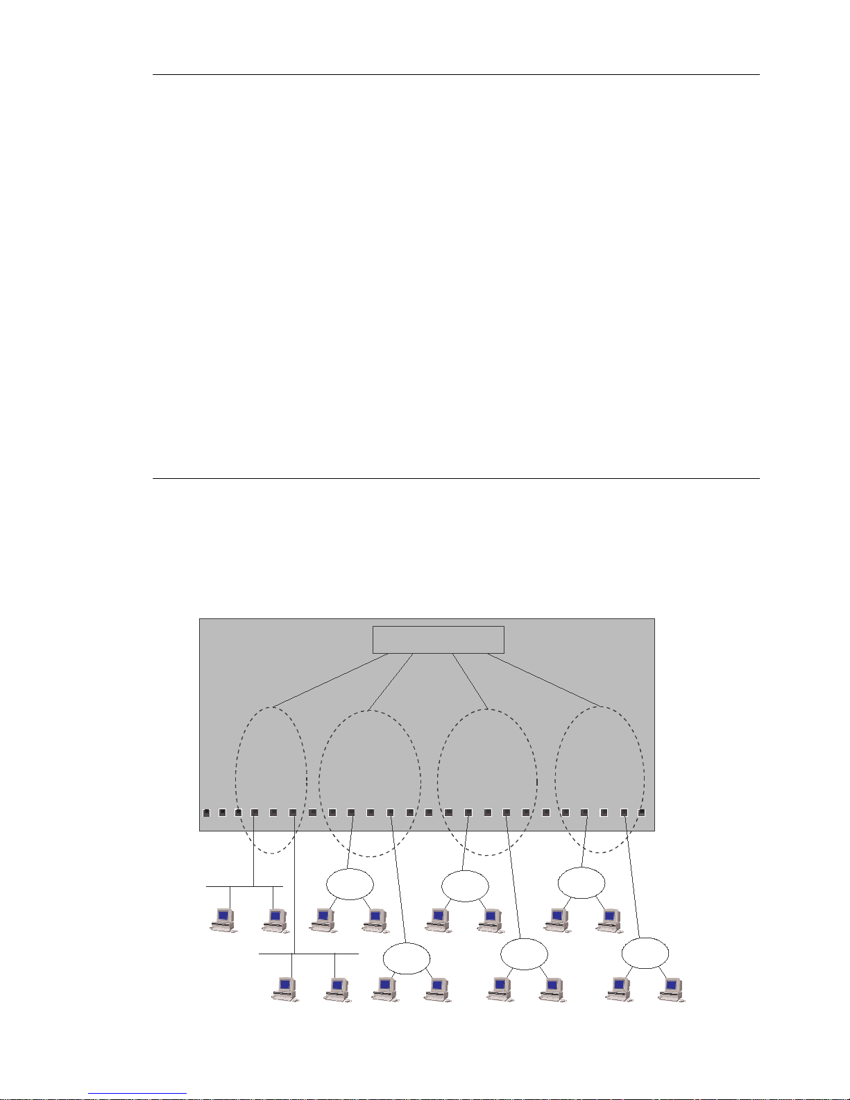
and SRT/SRB. The switch operates on two levels (BRF and CRF) as outlined below.
BRF 1
CRF 1
CRF 2
CRF 3
CRF 4
Switch
Figure 5. Typical Conf iguration with Switches Us ing Multiple Bridging Modes
CrossFire 8 730 Switch Ref erenc e Guide, DOC-7047 v. 1.1 Switch Overview
Page 32

18
The switch bridging modes are found ed on the concept of Logical Rings (LR) or
Logical S egments in Ethernet . The Log ical Ring is represe nted on the switch by the
DTR (IEEE 802.5r) sta ndard’s Concentrator Relay Functi on ( CRF ). A Logical
Ring may consist of interconnected CRFs on different switches.
Each port on the switch belongs to a CRF , which is a logical grouping of ports
within the switch. A CRF can consist of any number of ports within a switch or a
switch stack. The ports within a CRF do not have to be adj acent.
The Logical Rings and, subsequently, the CRFs , are assigned an unique ring
number each when the switch performs source routing functions. The bridging is
performed through the logical entity of the Bridge Rel ay Function (BRF).
The CRF communic ates via a logical , virtua l port with the Bridge Rel ay Functio n,
which functions as a multiport (virtual) bridge between the Logical Rings. The
switch can support up to 63 logical rings.
There are two levels of relay functions supported by the switch. The first level is
the TrCRF (Token-Ring Concentrator Relay Function) to which th e ports are
assigned . The second level i s the TrBRF (Token -Ring Bridge Rela y Function). This
is the parent relay function to which TrCRFs are as signed. The switc h ma intains
certain configuration information and management statisti cs on a per BRF/CRF
basis. Therefore, when you access VLAN-specific swit ch c onfiguration or
management scre ens (such as the
Current Spanning Tree Information
screen),
you will be prompted to specify the desired TrBRF for TrCRF.
For specific informati on for the Fas t Ethernet ports, see “Fast Ethernet Bridging
Modes” on page 23.
Source Route Switching (SRS)
This mode is used bet w ee n ports comprising a Logic al Ring.
SRS switch ing com bines the normal tr anspa ren t brid ge func ti on wit h the abil it y to
forward frames based on source route informati on to local ly attache d source-rout e
bridges. The switc h does not o the rwise a ct a s a sou rce route bridg e. For no n sou rcerouted packe ts, t he swi tch de cision i s bas ed upon dest inatio n MAC Addr esses . For
source-routed packets, it is based on the source-rout e information combi ned with
the destination MAC addres s.
The switch le arns MAC addresses and source-routing rout e descriptors of Source
Route Bridges attached to local switch ports.
Parallel paths are eliminated via the IEEE 802.1D Spanning Tree Protocol.
Source Route Bridging (SRB)
The BRF acts as a multiport S ource Route Brid ge between CRFs with the following
characteristics:
CrossFire 8730 Switch Reference Guide, DOC-7047 v. 1.1 Switch Overview
Page 33

19
•
Each Logical Ring ha s a different ring number
•
Source Route F r ames are forwarded between the Logical Ri ngs by the Bridge
Relay Functi on bas ed on the route information field
•
Non-source-route frames are not forwarded between logical rings
•
The Bridge Relay Function has a single bri dge number and multipl e ring
numbers (one per Logic al Ring)
SRS is used bet ween the port s of each logic al ring. The Bri dge Relay Fun ction runs
the IBM Spanni ng Tree Protoc ol to elimina te parall el paths with ot her source-rout e
bridges. The IEEE 802.1D Spanning Tree Protocol is still used with each logical
ring. Duplicate MAC addresses are allowed
Rings.
Source Route Transparent (SRT)
The BRF can combi ne transparent switching with Source Route Bridging. Non
source-routed packets are switched across logical rings by trans parent bridging.
Source-routed frames are switched across logical rings by Source-Route Bridging
and within e ach logical ring by Source-Route Switching.
if they are on different Logical
only
The Bridge Relay Function runs the IEEE 802.1D Spanning Tree Protocol.
Duplicate MA C ad dresses are
SRT/SR B
This is a spe cial mode combini ng SRT and the SRB switchi ng modes. Each Logic al
Ring will ope rate either in SRT mode or in SRB mode. Trans parent bridging will
only tak e place between logic al rings in SRT mode. Source-route bridgin g will tak e
place between all logical rings.
The purpose of the SRT/S RB mode is to a llow duplic ate MAC addre sses to be us ed
when in SRT mode. The ports on whic h the duplic ate MAC addresse s reside can be
reached only by source routing .
The Bridge Relay Function runs the IBM Spanning Tree Protocol on the SRB
logical rings to eliminate parall el paths with all source route bridges. It runs IEEE
802.1D Spanning T ree Protoc ol on the SRT logical rings to eli minate p arallel path s
with other SRT bridges. The two resulting spanning trees are joined toget her.
The IEEE 802.1D Spanning Tree Protocol is still used to eliminate parallel paths
within each logic al r ing whether it is SRB or SRT.
allow ed.
not
The benefit of th e SRT/SRB mode is that it allows part of the networ k to be run in
SRT mode to accom mo date applications that do no t support sourc e routing, while
still supporti ng duplica te MAC address es on a number of SRB ports (for exampl e,
for SNA gateway applications).
CrossFire 8 730 Switch Ref erenc e Guide, DOC-7047 v. 1.1 Switch Overview
Page 34

20
Filtering
Filtering is important for a LAN switch. Filters can be used to reduce broadcast
traffic, block certain protocols and provide security functions .
The switch provi des filters for:
•
Destination or source MAC addresses
•
Destination service access point (DSAP)
•
Subnetwork Acc es s Protocol (SNAP) type
Each protocol filter can be applied on a per-port basis for both input and output
traffic. This feature allows certain protocols to be blocked from certain ports . For
example, filters can be established to allow only Systems Network Architecture
(SNA) traff ic to flow to ports with S NA gateways.
Source and destination MAC address filtering can be applied to all incoming
frames. The MAC addres s filters act in one of three ways:
•
Block destination address at a specific port—this prevents the specified port
from sending frames to a specified destination.
•
Allow destination address at specific ports—this indicates that the specified
port must send frames to the specif ied destinations
•
Force destination address to a specific port—this allows forwarding to a
unicast address that has not been learned. It can also be used to limit the
forwarding of Multicast addresses to a subset of ports. This last filter applies
to non-source-routing frames
only
.
only
.
Congestion Control
At regular interva ls , the switch CPU inspects the queues on all Tok en-Ring output
ports. If a queue size is above a certain thres hold, the port is instructed to:
•
Set the transmit priority for low priority frames to a specified high level
•
Delete old frames from the queue until it reaches a specified size
When the queue size again comes below a normal threshold size the port is
instructed to set the transmit priority back to the normal level.
CrossFire 8730 Switch Reference Guide, DOC-7047 v. 1.1 Switch Overview
Page 35

21
Three Switching Modes
Cut-Through
In this mode the switch starts forwarding the packet to the output port as soon as
the destination address or the source-route of the incoming packet has been
resolv ed. This tech niqu e ensures very l ow late ncy , typic ally i n t he range of 30 -100
µs. However, if errors occur on the input port during the reception of a packet, the
error will still be forwarded to the output port. Note that cut-through ca n only be
used in trans mi ssions between ports which operat e at 16 Mbps.
This mode is only supported by the Token-Ring ports.
Store and Forward
In this mode, the switch receives the total packet f r om t he input port, che cks it for
any errors and then starts forwarding the packet to the destination port. This
techni que will ensure that no fau lty packets are tra ns mitted by output port . T he
negative impact howeve r , is higher latency, typically in the range of 40–2, 000 µs
depending on the packet size. Though slower than cut-through mode, this is still
much faster that convention al bridges.
The Fast Ethernet ports support this mode only.
Auto (Adapt ive C u t-T hrough)
This is a techn ique where by t he swit ch will aut omati call y swap be tween s tore-a ndforward and cut- through modes based on an err or threshold. If the number of
receiv ed faulty packets is low, then cut-through mode is used; if the numbe r of
faulty pac kets is high, the stor e and forward mode is used. This provides opti mized
performance but introduces variable laten cy.
CrossFire 8 730 Switch Ref erenc e Guide, DOC-7047 v. 1.1 Switch Overview
Page 36

22
Fast Ethernet
The following sect ions up to page 32 provides inform ation about Fast E thernet and
various network scenarios.
Fast Ethernet Ports
The Fast Ethernet ports are configured much like Toke n-Ring ports, and gene rally
appear in all tables where Token-Ring ports appear.
Fast Ethernet Virtual Ports and VLAN Tagging
For general inf ormation on VLAN support, see page 35.
Unlike Token-Ring ports, the Fast Etherne t ports can fun ction as trunk ports. This
means that they can carry traffic belonging to all of th e possible 63 VLANs over
the same physical cable connection.
Frames from differe nt VLANs are dis tinguished by means of standard IEEE
802.1Q frame tags. The tag is inserted in the Etherne t frame after the frame header
before transmission on the Fast Ethernet port, and subsequently recognized and
removed when the frame is received.
To identif y the VL AN to which the frame belongs, the f ram e ta g ma kes use of a
VLAN identifi er that uniquely ide ntifies the BRF. It also contains a 3 bit priority
field (described in section “Virtual Port Configuration” on page 41.)
Each Fast Ethe rnet port can be assigne d to several CRFs, but ther e ca n be only one
per BRF/VLAN. A vi rtua l port is created for each CRF to wh ich the Fast Ethernet
port is ass igned. All virtual ports but one must be tagge d (i.e., a singl e virtual por t
can be left untagged).
Note that a Fast Ethernet port with a singl e untagged virtua l port is functiona lly
equivale nt to an ordinary Token-Ring port. This is al so the default configuration,
with the virtual port in ethcr f-default.
Virtual Port Restriction
A Fast Ethernet port can have only one virtual port in each VLAN. This follows
from the nature o f VLAN taggi ng. Otherwi se it would not be possible to dis tinguish
frames from two virtual ports in the same VLAN, since they would have the same
VLAN iden tifier.
Ring Number Restriction
All CRFs in which a Fast Ethernet port has virtual ports must have the same ring
number. Thus, the ring number is a “per-port” par ameter and not a “per-virtu alport” paramet er. If this were not th e case, the meaning of the RIF would be
CrossFire 8730 Switch Reference Guide, DOC-7047 v. 1.1 Switch Overview
Page 37

23
ambiguo us and d epe nd on the VLAN to whi ch the f rame was sent. It would th us be
incompr ehe nsible to equipment that does not understand VLAN tags.
Fast Ethernet Port Operation Modes
Each Fast Ethernet port may operate in one of the following modes:
•
Half-duplex
In this mode the port offers a 10 Mbp s or 100 Mb ps connecti on from t he switch
to another switc h, a workstation, or a hub.
•
Full-duplex
In this mode the port offers a 10 Mbp s or 100 Mb ps connecti on from t he switch
to an ot h er s w it ch or a wo r k station .
Fast Ethernet Bridging Modes
For ge neral info rmation o n t he brid ging modes, see “Mult ipl e Bri dging Modes ” on
page 17.
Source Route Switchin g ( S RS)
SRS is the default mode of operation. This mode is also restored after a NVRAM
reset of the switch. In this mode, all Fast Ethernet ports are in the same CRF.
Frames are switched between ports bas ed only on MAC addresses. In this mode,
the spanning tree algorit hm is disabled by default. If more than one Fast Ethernet
port is used to connect to the Ethernet cloud, the IEEE Spanning Tree Protocol
should be enabled on the CRF.
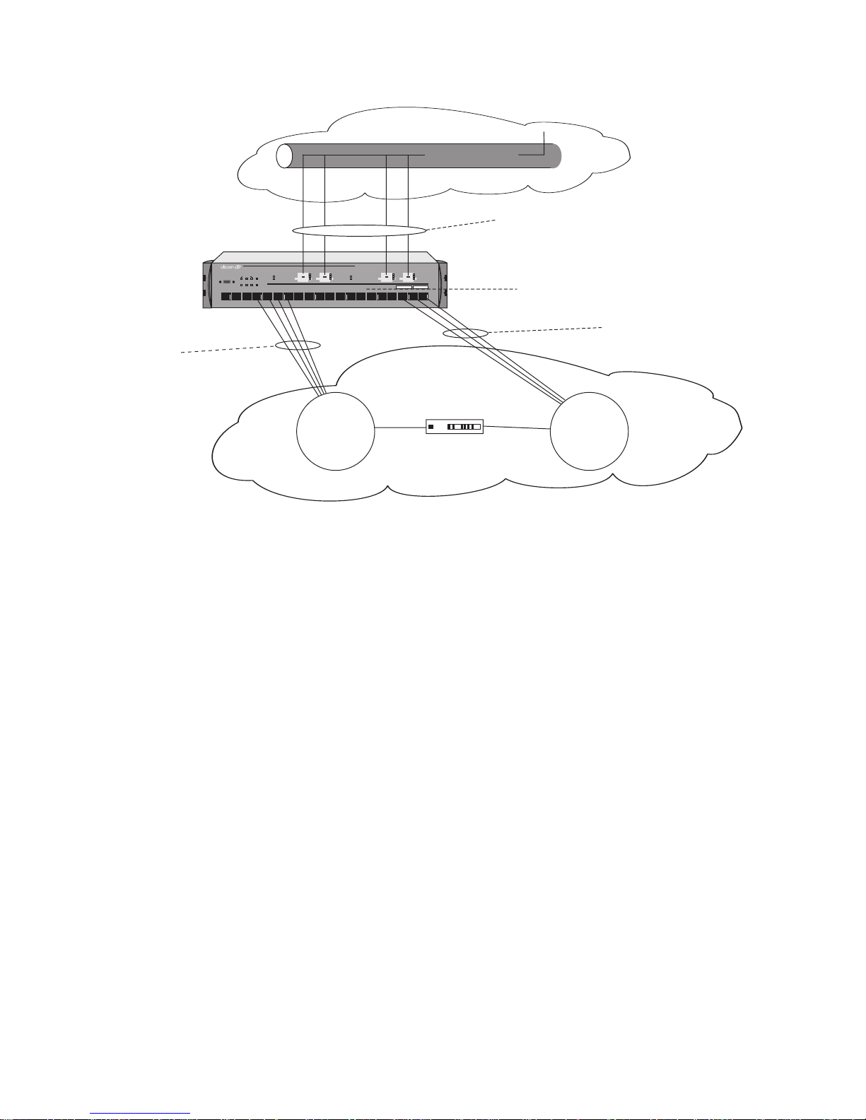
Source Route Transparent (SRT)
➽ Note
If mul tiple CRFs are used on a switch, al l Fast Ethernet links to the same Ethernet
cloud should be grouped into one CRF. If the spanning tree protoc ol is to be used,
enable the STP (spanning tree protocol) on the CRF and BRF. The CRF’s STP
should be set to IEEE; the BRFs’ STP shoul d be set to Based on Bri dgin g mode or
IEEE
Note that thi s tran slat ional C RF is used onl y on the T oken-Rin g side and i s used to
route sou r ce-routed Token-Ring frames toward the Ethe rnet cloud. See Figure 6.
: SRT is the suggested mode of operation.
.
CrossFire 8 730 Switch Ref erenc e Guide, DOC-7047 v. 1.1 Switch Overview
Page 38
24
CRF with
Token-Ring
ports in SRT or SRB mode
Ethernet cloud
All translational links grouped
into one CRF (SRT mode). If
more than one link is used, IEEE
STP must be enabled.
ACT
100
LINK
FASTETHERNET
CrossFire 8730
STATUS
FAULT
151211 1413 17161918 20
ACT
ACT
100
100
LINK
LINK
BRF with STP set to:
- Based on Bridging mode
STACK-LINK
ATTACH
RXTX
DIAGPWR RSTERRMANAGEMENT
3254
1
ACT
STATUS
100
LINK
FAULT
21
21-22 25-2622 2625
876109
FastEthernet Translation Switch
- IEEE.
CRF with
Token-Ring
ports in SRT or SRB mode
Figure 6. Source Route Transparent Bridging (SRT) Mode
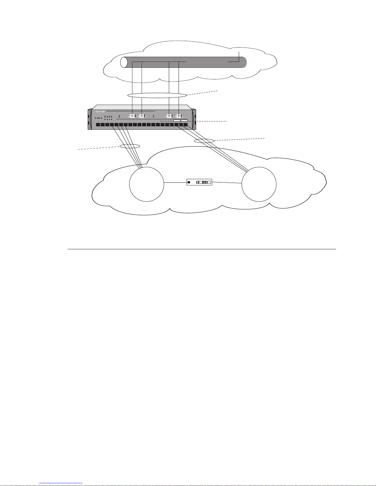
Source Route Bridging (SRB)
➽ Note:
If multiple CRFs are used on a switch, all Fast Et h ernet links to the same Ethernet
cloud shoul d be grouped int o one CRF. If a CRF is created in SRB Bridg ing m ode
and Spanning Tree is to be used, IEEE STP must be manually configured on th e
BRF and CRF.
Note that t his tr ansla ti onal CRF i s use d onl y on the Tok en-Ring s ide a nd is us ed to
route source-r outed Token-Ring frames toward the Ethernet cloud. See Figure 7.
Token-Ring
cloud
SR Bridge
SRT is the suggested mode of operation.
Token-Ring
cloud
CrossFire 8730 Switch Reference Guide, DOC-7047 v. 1.1 Switch Overview
Page 39
STACK-LINK
RXTX
DIAGPWR RSTERRMANAGEMENT
3254
1
CRF with
Token-Ring
ports in SRT or SRB mode
ATTACH
876109
ACT
STATUS
100
LINK
FAULT
21
21-22 25-2622 2625
ACT
100
LINK
FASTETHERNET
CrossFire 8730
STATUS
FAULT
151211 1413 17161918 20
FastEthernet Translation Switch
ACT
ACT
100
100
LINK
LINK
25
Ethernet cloud
All translational links grouped
into one CRF (SRB mode). If
more than one link is used, IEEE
STP must be enabled.
BRF with IEEE STP enabled
CRF with
Token-Ring
ports in SRT or SRB mode
Token-Ring
cloud
SR Bridge
Token-Ring
cloud
Figure 7. Sour ce Route Bridging (SRB) Mode
Redundant Connections to Fast Ethernet Network
A connection to the Ethernet cloud can be made using several Fast Ethernet ports
from multi ple switc hes. F ast Et hernet port s con nected fro m on e switch to t he s ame
Ethernet cl oud should be grouped int o one common CRF with an assign ed LAN
segment number. From each switch, one CRF can be conn ected to the same
Ethernet cloud.
Redundan t connections betwe en s ource-routed and t r ansparent networks ma y
cause AR E frame dup lication and infi nite ARE frame loops as a r esult o f disca rding
source routi ng informati on during transla tion from Token-R ing to Ethernet format.
There are, however, solutions to both problems:
•
Infinite frame l oops are el imina ted by using a c ommon LAN segmen t number
for the entire Ethe rnet cloud or by proper Spanning Tree configuration. The
recommended CRF number is 4095.
•
Frame duplication is eliminated by a proper STP configuration allowing only
one link between the Token-Ring cloud and the Ethernet to be forwarding.
See the next section “Network Scenarios—Preventing Frame Duplication and
Looping” on page 26 for details.
CrossFire 8 730 Switch Ref erenc e Guide, DOC-7047 v. 1.1 Switch Overview
Page 40
26
Network Scenarios—Preventing Frame Duplication and
Looping
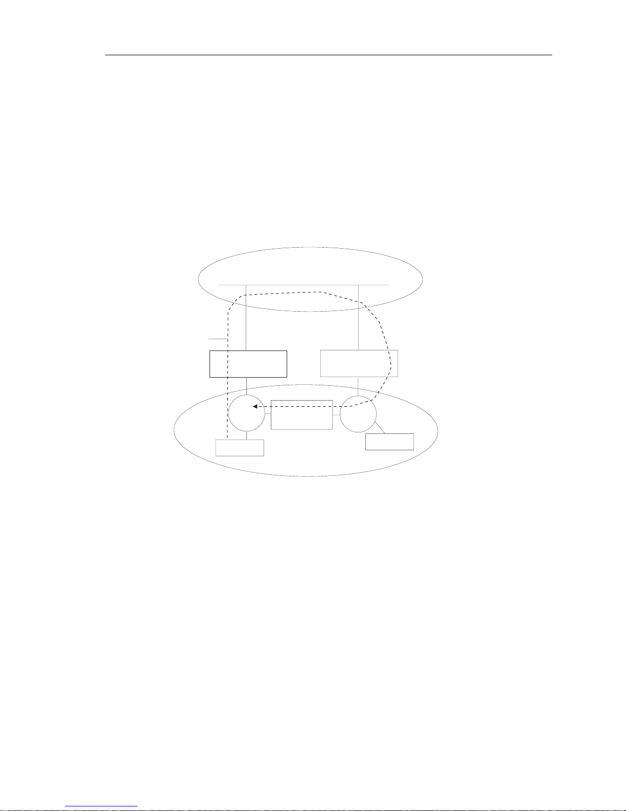
This secti on discuss es preventin g frame duplica tion and fra me looping i n networks.
Preventing Frame Duplication
The ARE duplica tion problem can occur only in a configurat ion with redundant
Fast Ethernet ports in different switch es (as in the configurati on that follows).
It is assumed that th e network consists of a physica lly connected Etherne t cloud and
a physical ly co nnecte d Token- Ring cloud. T he two clo uds are then conn ecte d by a
number of links that implement translational bridging. See Figure 8. below.
Ethernet cloud
LAN segment 3
ARE frame
generated from
Station A
CrossFire 8730 - Link 1
Forwarding
Ring 1
Station A
Redundant
connections
to Ethernet
Bridge 1
Token-Ring
cloud
CrossFire 8730 - Link 2
Forwarding
Ring 2
Station B
Figure 8. Preve nting Frame Duplication
In a pure Token-Ring ne twork, an All Routes Explorer (ARE) frame generated
from Station A traverses all rings only one time based on a Routing Information
Field (RIF) expan ded by each source-routed bri dge. In this example, both Fast
Ethernet l inks a re in the for warding s t ate. An ARE fr ame or igina tin g in Ri ng1 m ay
go through the Ethernet cloud and come back to Ring 2. Because the RIF is lost
when passing thr ough the Etherne t cloud, LAN segment 1 is no longer inc luded in
the new RIF and the frame will be forwarded by Bridge 1 from Ring 2 back to Ring
1. This results in frame duplication – a fter visiting Ring 1 again, the frame will be
discar ded by the Fast Ethernet ports connected to Ring 1.
This issue can be resolved by making sure that only one Fast Ethernet port can be
in the forwarding state.
CrossFire 8730 Switch Reference Guide, DOC-7047 v. 1.1 Switch Overview
Page 41
27
Preventing Frame Looping
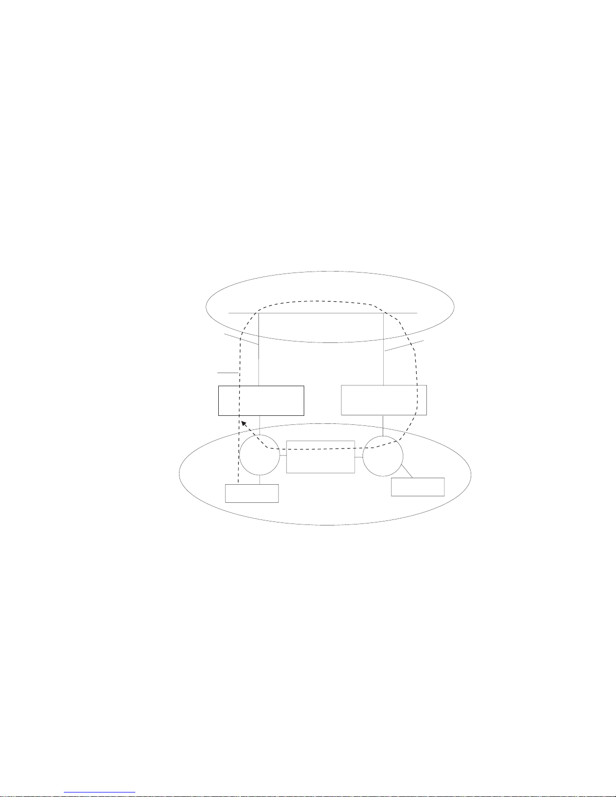
The previous network scenario was free of the ARE looping issue because the
entire Ethernet cloud had the same LAN Segment number.
In the next scenari o, the Fast Ether net ports have differen t LAN segment nu mbers.
In th is c onfigura tio n, an infi nit e loop is crea ted i n a ddit ion to the fram e dupli cati on
issue.
Station A s ends an ARE frame to Ri ng1 – ex. IP ARP with de sti nation MAC being
Broadca st . This frame is converted to a transp arent broadca st and sent on Ethernet
link 1. The fr ame is t hen rec eiv ed by the Fast Ethe rnet port on li nk 2 and se nt as an
ARE frame to Ring 2 – note that the RIF does not contain LAN Segment 4. The
ARE frame is then forwarded by Bridge 1 and link 1 back to the Ethernet, and so
on. See Figure 9. below.
Ethernet cloud with different LAN
segment numbers on each CRF
LAN segment 4
ARE frame
generated from
Station A
CrossFire 8730 - Link 1
Forwarding
Ring 1
Station A
Redundant
connections
to Ethernet
Bridge 1
Token-Ring
cloud
CrossFire 8730 - Link 2
Forwarding
Ring 2
LAN segment 3
Station B
Figure 9. Frame Looping
This loo p c an be resol ved by makin g sure t hat on ly one F ast Ether net li nk can be in
the forwarding state or by using the same LAN segment num ber for al l F as t
Ethernet links.
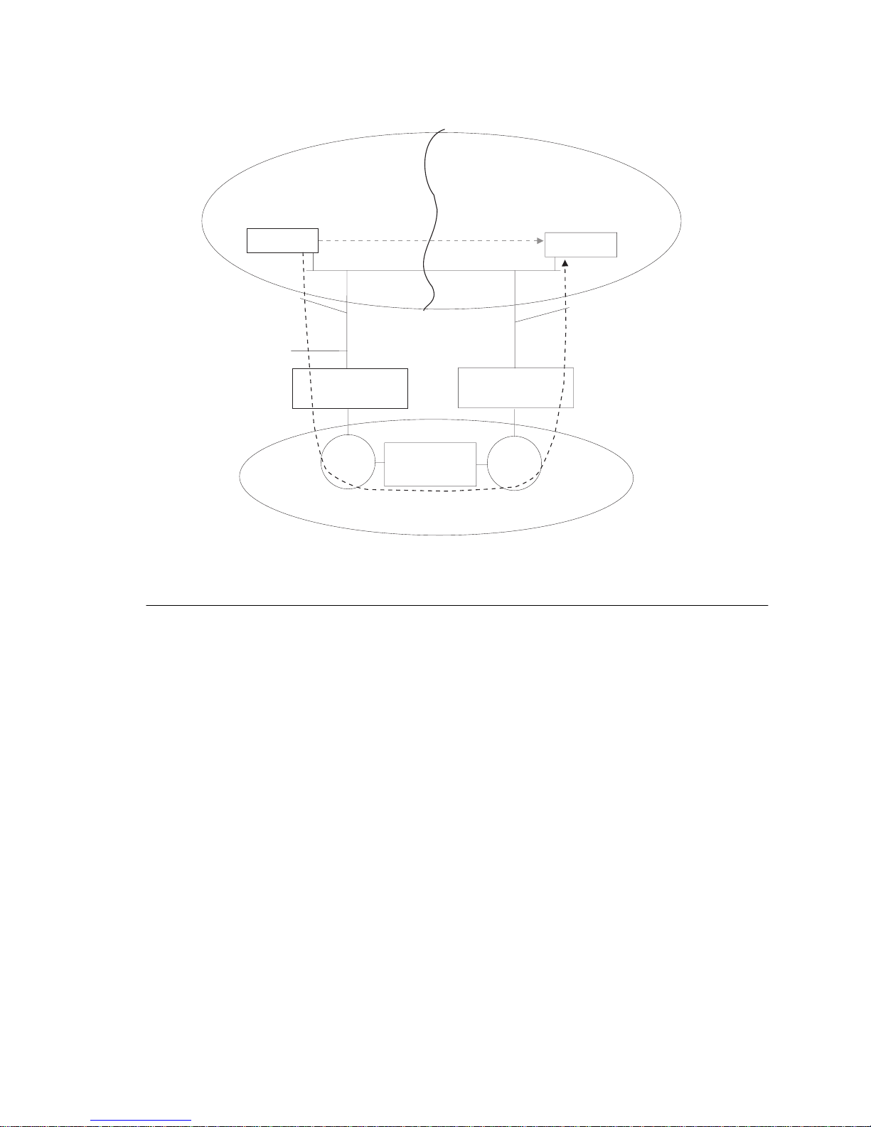
Using t wo diffe rent L AN segme nt numb ers h as some int eresti ng adva ntages. If the
Ethernet c loud be come s physic ally sepa rated i nto two p arts (s ee be low), bot h pa rts
can still communicate via the Token-Ring cloud. If the Ethernet cloud is not split
and the root of the spa nnin g tr ee is o n the T oken-Ri ng si de, ther e mig ht b e a l os s of
connectivi ty bet ween Etherne t stations de pending on the CRF num bers configu red.
CrossFire 8 730 Switch Ref erenc e Guide, DOC-7047 v. 1.1 Switch Overview
Page 42
28
To avoid those hazardous situations, follow the recommendations in section
“Spanning Tree Configurat ion for F as t Ethernet” below.
Ethernet cloud broken into two
separate clouds.
The direct connection between
station A and B is broken.
Station A
X
Station B
LAN segment 4
Frame generated from
Station A is still passed
to station B
CrossFire 8730 - Link 1
Forwarding
Ring 1
Redundant
connections
to Ethernet
Bridge 1
Token-Ring
cloud
CrossFire 8730 - Link 2
Forwarding
Ring 2
LAN segment 3
Figure 10. Preventing Frame Looping
Spanning Tree Configuration for Fast Ethernet
Running the IEEE Sp anning T ree Prot oco l (STP) will cre ate a sing le sp anning t ree
covering the e nti re ne twork. Depe nding on th e topology a nd confi gure d path c osts,
there will be one or more forwarding links be tween the two clouds.
If ther e are m ultipl e Fast E thernet links in multi ple switc hes, th e path c osts on t hese
links should be selected such that only one forwards. This will prevent ARE
duplication and the looping problem.
Normally this can be achieved by assigning very large path costs on both sides of
the Fast Et h ernet links such that at most one can be forwarding . The Fast Ethernet
ports provides support for STP cost manipulation which does not require cost
configuration on both side s of the link.
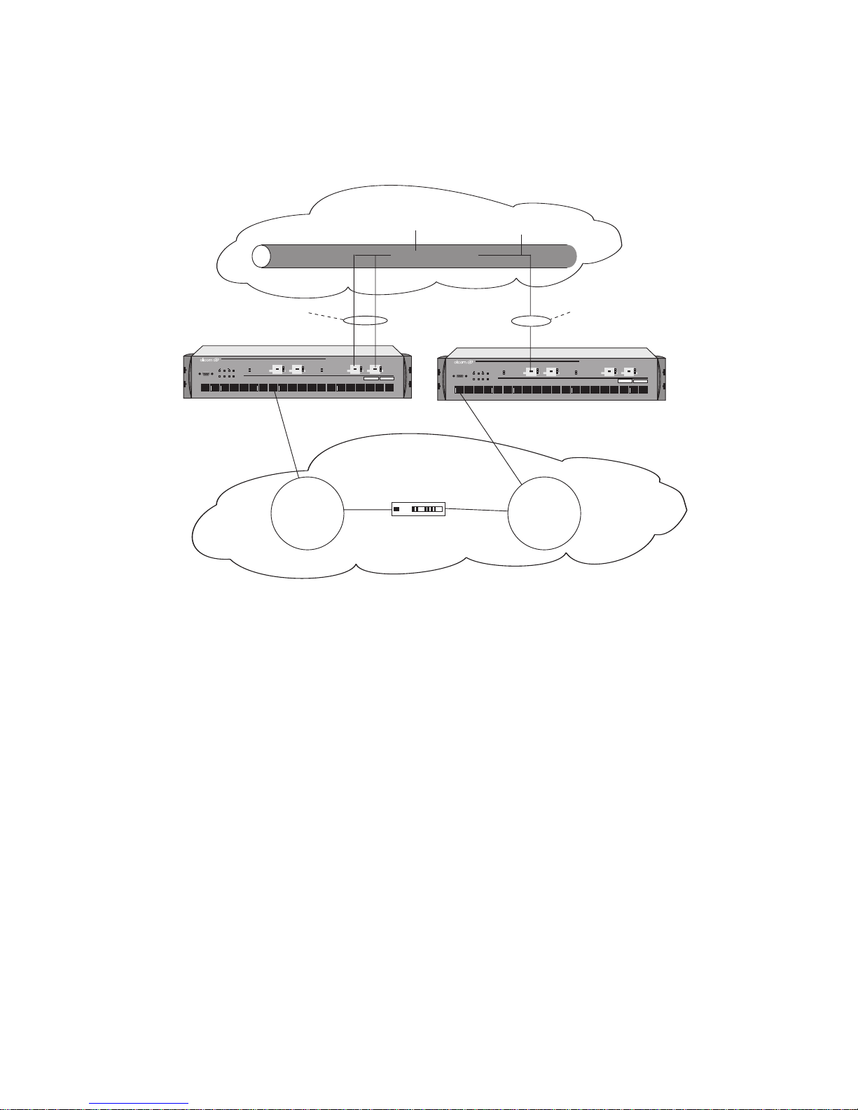
For each CRF of Fast Ethernet ports connected to the same Ethernet cl oud, a
connection attribute ca n be ass igned (see “TS Connection” on page 56):
•
Primary connection
value for each CRF). This connection is alwa ys forwarding if ac tive .
•
Secondary 1
– for a backu p con necti on to the Et hernet cl oud. Thi s conn ecti on
is alw ays blocking if the pr imary is active.
CrossFire 8730 Switch Reference Guide, DOC-7047 v. 1.1 Switch Overview
– for a main connection to the Ethernet cloud (default
Page 43
29
•
Secondary 2
connection is always blocking if
– for a second backup connection to the Ethernet cloud. This
Primary
or
Secondary 1
are active.
Each CRF of Fast Ethernet ports connected to the same Ethernet cloud must have
a different connection attribute set. See Figure 11.
Ethernet cloud
Primary CRF
FORWARDING
STACK-LINK
ATTACH
RXTX
DIAGPWR RSTERRMANAGEMENT
3254
1
ACT
100
LINK
FASTETHERNET
CrossFire 8730
STATUS
FAULT
151211 1413 17161918 20
ACT
STATUS
100
LINK
FAULT
21
21-22 25-2622 2625
876109
FastEthernet Translation Switch
ACT
ACT
100
100
LINK
LINK
STACK-LINK
STATUS
FAULT
21
21-22 25-2622 2625
ATTACH
RXTX
DIAGPWR RSTERRMANAGEMENT
3254
1
876109
Secondary CRF
BLOCKING
ACT
ACT
STATUS
100
100
LINK
LINK
FAULT
FASTETHERNET
CrossFire 8730
151211 1413 17161918 20
FastEthernet Translation Switch
ACT
ACT
100
100
LINK
LINK
Token-Ring
cloud
SR Bridge
Token-Ring
cloud
Figure 11. Spanning Tree Configuration
The described spanning tree configuration results in exactly one forwarding link
between Ethernet and Toke n-Ring cl ouds, addit ional li nks be comin g stand-b y. For
custome rs migrating from Token-Ring to Etherne t it is recommended over time t o
physic ally split t he Token-Ri ng cloud i nto disj oin t networ ks to inc re ase bandwidt h
between Toke n-Ring and Ethernet.
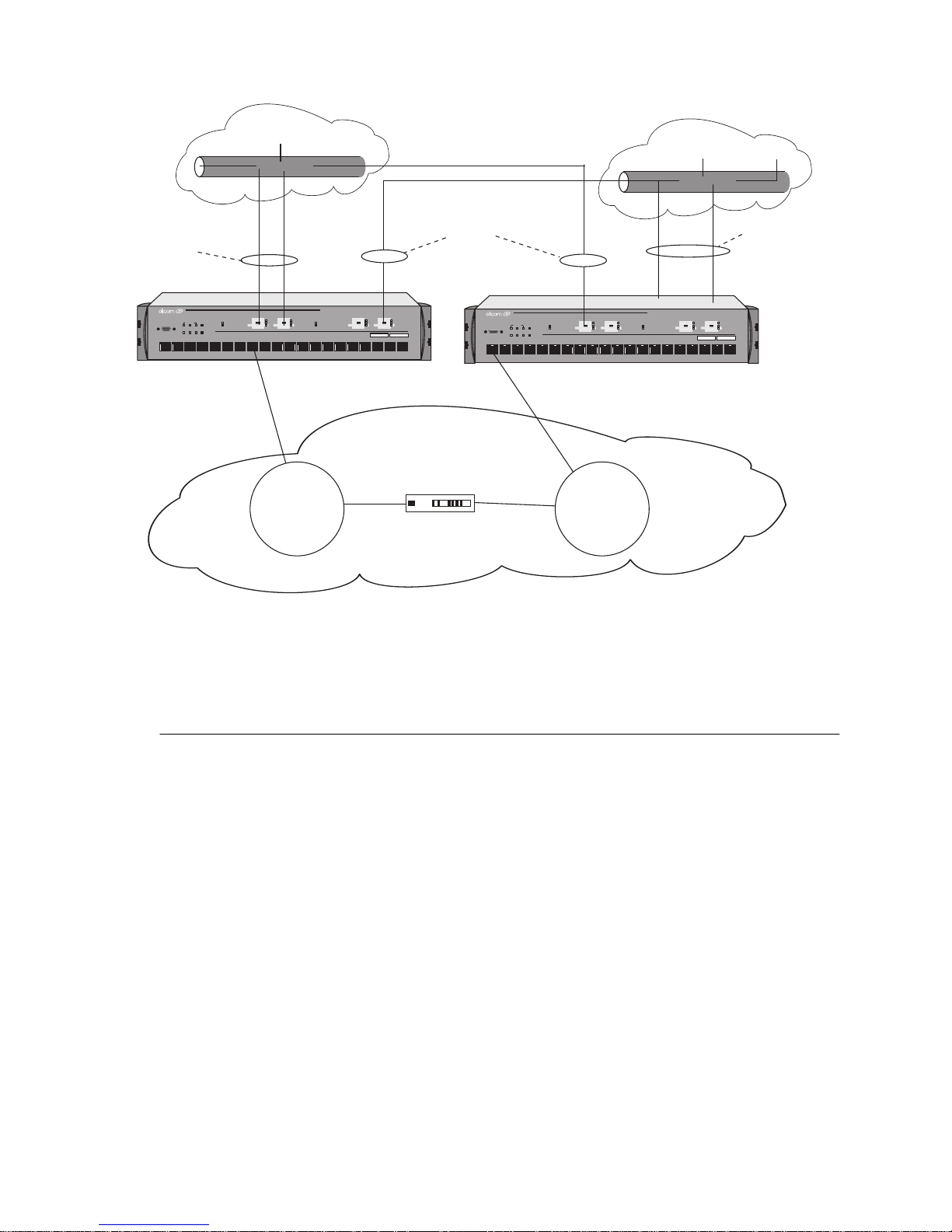
Figure 12. below illustrates a network with two physically disjointed Ethernet
clouds. E ach switch in the configuration has one primary c onnection to one of the
two Ethernet clouds and one seconda ry connection to the other cloud.
This way re dundancy for both Et hernet clouds is provided, while at th e sam e time
the traffic load between the Token-Ring and Ethernet clouds is split between the
two switches.
CrossFire 8 730 Switch Ref erenc e Guide, DOC-7047 v. 1.1 Switch Overview
Page 44
30
.
Primary CRF
FORWARDING
STACK-LINK
1
Ethernet cloud
ACT
STATUS
100
LINK
FAULT
21
21-22 25-2622 2625
ATTACH
RXTX
DIAGPWR RSTERRMANAGEMENT
3254
876109
Token-Ring
ACT
100
LINK
FASTETHERNET
cloud
CrossFire 8730
STATUS
FAULT
151211 1413 17161918 20
FastEthernet Translation Switch
ACT
ACT
100
100
LINK
LINK
Secondary CRF
BLOCKING
SR Bridge
Ethernet cloud
Primary CRF
FORWARDING
ACT
100
LINK
FASTETHERNET
CrossFire 8730
STATUS
FAULT
151211 1413 17161918 20
ACT
ACT
100
100
LINK
LINK
STACK-LINK
ATTACH
RXTX
DIAGPWR RSTERRMANAGEMENT
3254
1
ACT
STATUS
100
LINK
FAULT
21
21-22 25-2622 2625
876109
FastEthernet Translation Switch
Token-Ring
cloud
Figure 12. Two Separate Ethernet Clouds
➽ Note:
Technical Background
For each CRF with a Fast Ethernet port, the spanning tree protocol should be
enabled. For SRT CRF, the default STP al gorithm is IEEE 802.1D. Only this
spanning tree algorithm can be used for Fast Ethernet ports .
A Fast Ethernet port has its own LAN segment number and recognizes source
routing. Howe ver, th e Fast Ethernet por t is an element of a tr ansparen t network and
frames ar e pass ed t hrough only i n f orward ing state . Thi s re stric tion is a ppli ed to a ll
frames, including ARE and specifically routed frames.
Only one link of a CRF at a ti me may become forwarding . To a chieve this, the
spanning tr ee costs of the internal BRF to CRF link will be modified acc ording to
the CRF conn ection attribute. The BRF to CRF link is a virtual internal link and
exists only for spanning tree purposes.
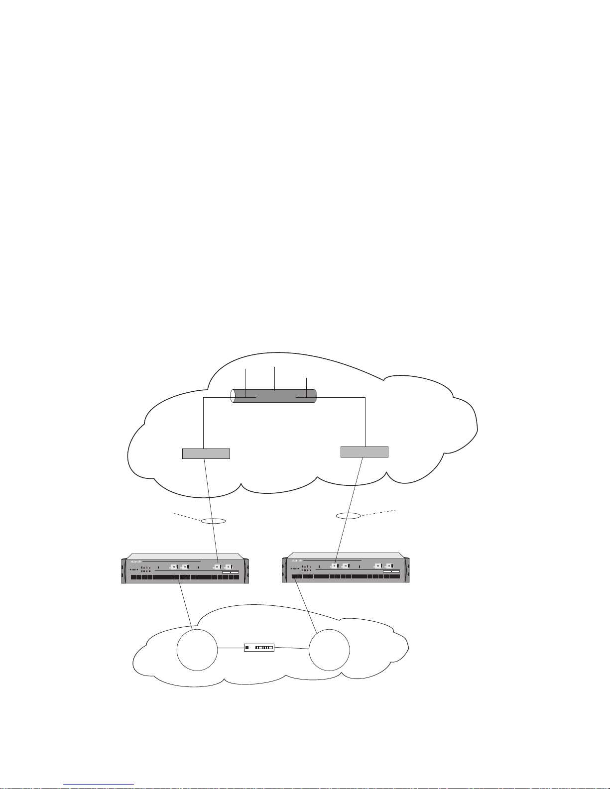
The spanning tree cost of each primary connection remai ns unmodified.
The CRF connection attribute can be set from the console or via ClearSight.
Note that in the
Secondary 1
added to the cost of th e in tern a l BRF to CR F link in or d er to ma ke sure that
CrossFire 8730 Switch Reference Guide, DOC-7047 v. 1.1 Switch Overview
and
Secondary 2
connections, different values are
Page 45
31
Secondary 1
Secondary 2
will become forwarding first, when the primary connection fails. The
connection is chosen only afte r the
Secondary 1
connection.
Cost modification of BRF to CRF link:
•
For the
Secondary 1
connect ion, a v a lue of 20,0 00 will be add ed to the cost of
the inter nal BRF to CRF lin k.
•
For the
Secondary 2
connect ion, a v a lue of 40,0 00 will be add ed to the cost of
the inter nal BRF to CRF lin k
In th e pict ure be low, th e C rossFi re 8730 Switc h 2 and Et hernet Switc h 2 know t ha t
the root path cost seen from the secondary link is 20,000 bigger, than the root path
cost of the prim ary link seen by the Cros s Fire 8730 Switch 1 and Ethernet Switch
1. This means that the secondary link will be blocked on the internal CRF to BRF
link.
If the spanning tree costs are configured manually for backup connection to
Ethernet, each connecti on attribut e should be set to
Primary
and then spann ing tree
costs must be cha nged on each side of the backup li nk.
Primary CRF
translational
connection. On
this CRF, the STP cost
stays unmodified.
ACT
STACK-LINK
ATTACH
RXTX
DIAGPWR RSTERRMANAGEMENT
3254
1
ACT
STATUS
100
100
LINK
LINK
FAULT
21
21-22 25-2622 2625
876109
Token-Ring
cloud
Ethernet Switch 1
FastEthernet Translation Switch
CrossFire8730
ACT
100
LINK
151211 1 413 17161918 20
ACT
100
LINK
STATUS
FAULT
FASTETHERNET
CrossFire Switch 8730 1
SR Bridge
Ethernet
STACK-LINK
STATUS
FAULT
21-22 25-2622 2625
ATTACH
RXTX
DIAGPWR RSTERRMANAGEMENT
3254
1
Token-Ring
cloud
Ethernet Switch 2
FastEthernet Translation Switch
CrossFire8730
ACT
ACT
100
100
LINK
LINK
21
FASTETHERNET
876109
STATUS
FAULT
151211 1 413 17161918 20
ACT
ACT
100
100
LINK
LINK
CrossFire 8730 Switch 2
Secondary CRF
translational connection.
On this CRF, the STP cost of
the internal BRF to CRF link
is modified.
Figure 13. STP BPDU Cost Modificat ion
CrossFire 8 730 Switch Ref erenc e Guide, DOC-7047 v. 1.1 Switch Overview
Page 46

32
Token-Ring
The following se ctions “Token-Ri ng Port Operation Modes”, “RI/RO-Like
Connecti on”, “Transmission Priority Queues ”, and “CrossLink Connections”
contains information that only applie s to the Token-Ring ports.
Token-Ring Port Operation Modes
Each Token-Ri ng port may operate in one of the following modes:
•
Half-duplex concentrator port
The port behaves like an active MAU port for class ical Token-Ring. C onnects
to a single station in half-duplex mode. This is also known as Token Passing
(TKP) port mode.
•
Half-duplex station emulation
The port i s conne cted t o a port on a MAU. Conn ects to a cl assic al To ke n-Ri ng
segmen t with multiple stations. This is also known as Token Passing (TKP)
station mo de.
•
Full-duplex concent rator port
Connects to a single station or to another switch in full-dupl ex mode. This is
also known as Transmi t Immed iate (TXI) port mode.
•
Full-duplex station emulation
Connects to another Token-Ring switch. This is al so known as Tr ansmit
Immediate (TXI) stati on mode.
•
RI/RO-like connection
The mode of operation can be configured manual ly or sensed automatically with
the excepti on of RI/RO, when equi pment is connect ed to the port. The medi a speed
(4 or 16 Mbps) can al so be manua lly co nfigu red or automati call y sensed in all por t
modes.
RI/RO-Like Connection
On CrossFire 8730, a RI/RO-like connection is available on ports 19 and 20.
This feature allows the switch to connect to CAU/LAM systems using the RI/RO
connect ions thus providing a RI/RO-like functionality. This enable s the switch to
be ea s il y installed in ex isting Tok en-R i ng net w or ks.
A loop-back function has been implemented on these ports so that if the port is
disabl ed or the switch is powered off there will not be a bre ak in the at tache d main
ring. This means that attaching a ca ble from the RI port of a MAU port to one of
the two swi tch ports in e ffect joi ns the primar y and the backup r ing in a MAU/CAU
main ring system. Connecting the other end of the RI/RO connect ion to the oth er
CrossFire 8730 Switch Reference Guide, DOC-7047 v. 1.1 Switch Overview
Page 47

33
switch port,
the same segment .
enabled
there i s a break in th e main ring, t he STP will pla ce both port s in forward m ode, and
all MACs on both segme nts will be relearne d.
If a switch por t h as been configur ed to RI/RO mode, it will automati cally sense
whether the port has been connected to RI or RO of the MAU.
➽ Note:
connected according to th e configur ation. Any errors, such as attaching port 19 or
20 to a normal MAU port when the CrossF ire 8730 port has been configured for
RI/RO, will ca use a complete disrupti on of the ring to which the por t is attached.
Therefore, be careful when u sing th e RI/RO feature.
Transmission Priority Queues
To address the needs of delay - se nsitive dat a, such as multime dia, the Token-R ing
ports of the switch have two transmit queues, a high-priority queue and a lowpriority queue.
creates r edundant pat hs
because the two s witch p orts ar e co nnecte d t o
Therefore, the IEEE Spanning-Tree Protocol (STP) must be
, which will place one port in forward and the other in blocked mode. If
It is not possible to automatical ly verify whether an UTP/STP port has been
The queue for a frame is determined by the value of the pri ority field in the frame
control (FC) byte . If FC priority is abov e a configurable lev el (default 3), the frame
is put int o the high-priority queue. If an output port becomes congested, you can
dynamically configure the port to transmit all frames at high priority regardless of
the FC byte contents.
Enabled FC modification on Fast Ethernet virtual ports preserves frame pr iority
during translation between Ethernet 802.1Q Tagged frames and Token Ring
frames.
CrossLink Connections
Two switch stacks or switches may be interconnected by a number of parallel
Token-Ri ng connections (up to 256 Mbps using eight Token-Ring ports). The
traf fic between the switches will be shared between the conne ctions.
CrossFire 8 730 Switch Ref erenc e Guide, DOC-7047 v. 1.1 Switch Overview
Page 48

34
Spanning Tree Protocol Su pport
The CrossFire 8730 supports the spanning tree protocols most often used in both
Ethernet and Token-Ring topologie s . The switch s upports IEEE 802.1D Spanning
Tree for all Ethernet ports, and both IEEE 802.1D Spanning Tree and IBM
Spanning Tree Protocols for Token-Ring ports. This makes it easy to integrate the
switch int o most existing Token-Ring and Fast Ethernet installations .
For more infor mation on s pannin g tree, see “Spa nning Tr ee Confi gurati on for Fa st
Ethernet” on pa ge 28 and “Spanning Tree Protoc ol” on page 64.
IBM initially supported only Source Route Bridging (SRB) in its bridges , s o most
Token-Ring networks were built to use it. The main consideration for SRB
implementations in switches is the spanning-tree algorithm for spanning tree
explorers (S TEs). IBM ori ginall y implemente d a form of the Institut e of Electri cal
and Electroni cs Engineers (IEEE) spanni ng-tree algorithm. This algorithm,
commonly referre d to as t he IBM spanning tre e, li mits t he STE fr ames t o one cop y
per destina tion ring . Som e SRB impl ementat ions ha ve also im plement ed the IE EE
Spanning Tree Pr otocol to be compatible with SRT bridges. The IEEE Spanning
Tree Protocol is not compatible with the IBM Spanning Tree Protocol.
CrossFire 8730 Switch Reference Guide, DOC-7047 v. 1.1 Switch Overview
Page 49

VLAN Support
The virtual LAN (VLAN) concept creates a virtual switch within a physical switch.
Frames are not forwarded between VLANs unless directed via a router or layer-3
switch.
The CrossFire 8730 provides the following VLAN functio nality:
•
No frames are forwarded between ports belonging to different VLANs.
•
Each VLAN may be assigned a separate IP address.
•
Spanning Tree determin ation is ex ecuted indepen dently within each VLAN.
VLANs on the Token-Ring Side
On the Token-Ri ng side , VLANs are se t up on a per-port ba sis . This mea ns tha t all
stations connecte d to a port must be part of the same VLAN. VLAN tagging i s not used.
IEEE 802.1Q ta gged VLANs entering the switc h from the Fast Ethernet side are
translated into port-ba sed VLANs on the Token-Ring side (and vice-versa).
35
Port groups on different VLANs may be assig ned the same ring number, but ring
numbers must be unique within the same VLAN.
VLANs on the Fast Et hernet Sid e
On the Fast Ethernet side, IEEE 802.1Q VLAN tagging is applied. This enables
traffic from several Token-Ring port-based VLANs to pass over a single Fast
Ethernet link. Furthermore, Q-tagged VLAN information is able to travel further
into the network so VLAN information will be preserved by all equipment that
supports Q-tagging, regardless of the manufacturer or topology.
IEEE 802.1Q ta gged VLANs entering the switc h from the Fast Ethernet side are
translated into port-ba sed VLANs on the Token-Ring side (and vice-versa).
The follo wing figure illustrates an example of a VLAN with a CrossFire 8730
Switch.
CrossFire 8 730 Switch Ref erenc e Guide, DOC-7047 v. 1.1 Switch Overview
Page 50
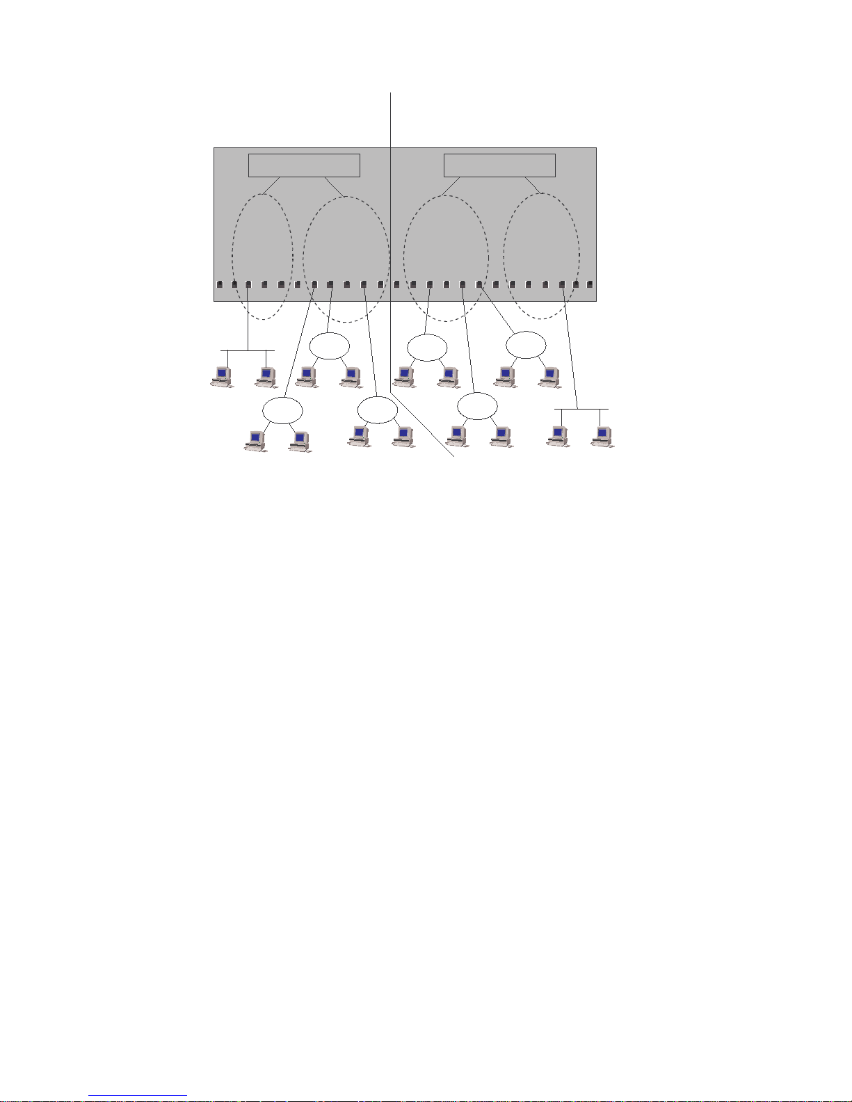
36
CRF1
VLAN 1
BRF 1
CRF2
VLAN 2
BRF 2
CRF3
Figure 14. A Switch Configured with Two VLANs
CRF4
Switch
CrossFire 8730 Switch Reference Guide, DOC-7047 v. 1.1 Switch Overview
Page 51

Managem en t
SNMP
The switch can be managed via a SNMP manager. It supports ten Management
Informat ion Bases (MIBs). S ix of the MIBs a re s tandard MIBs, which are defined
by RFCs and are incl ude d with mos t SNMP manageme nt applic at ions. Four of the
MIBs are proprietary and are provided on the disk that accompanies the switch.
SNMP management is supported via IP.
The follo wing MIBs are supported:
Specification MIB
RFC1213 SNMP MIB II
37
RFC1493 Bridge MIB
RFC1525 SR Bridge MIB
RFC1573 Evolut ion of the Interfaces
Group of MIB-II
RFC1757/1513 RMON MIB/TR extensions -
only partia l support
RFC1749/1748 IEEE 802.5 MIB
DTR MIB IEEE 802.5r MIB
DTR MAC MIB IEEE 802.5r MIB
Olicom oc8600 unit MIB
oc8660 unit MIB
Olicom/Cisco VTP MIB
Table 11. Supported MIBs
Most user configurable var iables will be suppo rted in either the standard MIBs or
the proprie tary MIB. Configurati on settings, such as port at tributes, and operati onal
information, such as address tables, are fully accessible through SNMP. Certain
other settings, such as pass w ords and console settings, cannot be viewed or
modified via SNMP for security reasons.
CrossFire 8 730 Switch Ref erenc e Guide, DOC-7047 v. 1.1 Switch Overview
Page 52

38
Switch Manager for HP OpenView for Windows
The Switch Manage r is an applica tion that runs unde r HP OpenView for Windows.
It provides an intuitive graphical user interface (GUI) that displays a chassis
physical view and supports configuration, performance monitoring, and
troubleshooting.
This appl ication i s inc luded with the switch.
For informati on about Switch Manage r on other platforms, ple as e contact your
local Olicom sales representative.
Telnet Management and VT100 Ma nagem ent (Console)
The Con sol e Management function may be accessed out-of-band via t he TIA/EIA232-F (i.e. RS-232) port labelled MANAGEMENT or in-band via Telnet.
IBM LAN Network Manager
The switch does
support management by the IBM LAN Network Manager, but
not
it will al low LAN Network Man ager LLC frames to fl ow through t he switch so t hat
communicati on to exist ing LNM manage able hubs and source route b ridges wil l be
mainta ined.
Some error reporting functions and ring map functions might be lost for the rings
attach ed to through the switch, because a Token-Ring Switch will not (and should
not) forward MAC frames, but only LLC frames between ports.
CrossFire 8730 Switch Reference Guide, DOC-7047 v. 1.1 Switch Overview
Page 53

RMON Support
RMON is an indus tr y-standa rd me thod for provi din g ne twor k stati stic s monit ori ng
using SNMP. I t a lso coll ec ts fault , pe rforma nce, and confi gurati on sta tis tics . It can
monitor continuously, even when communication with the management station is
not possible or efficient. RMON can then notify the management s tation when an
exceptional condition occurs.
In ty pical SNMP management, the SNMP cl ient has to conti nuously pol l the switch
for fault, performance, and configuration information, waiting for the value to
change. Thi s causes increased traffic through the network. With RMON, you can
have the switch monitor a particular s tatistic internally, and whe n the statistics
reaches a threshold, the switch will send a trap to the client. This monit oring
method reduces traffic betwe en the SNMP client and the switch.
The fol lowing groups are supported in RFC-1513 Token-Ring Extensions RMON
MIB
39
•
The Token-Ring Mac-Layer Statistics Group
•
The Token-Ring Promiscuou s Statistics Group
•
The Token-Ring Mac-Layer History Group
•
The Token-Ring Promiscuou s History Group
•
The Token-Ring Ring Stati on Group (S ETs not supported)
•
The Token-Ring Ring Station Order Group.
The Followi ng Groups are supported in RFC-1757 RMON MIB for both TokenRing and Fast Et hernet ports.
•
The Statistics Group (group 1)
•
The History Control Group (group 2)
•
The Event Group (group 9)
•
The Alarm Group (group 3)
Full RMON support for a selected subset of ports is implemented by an external
RMON Probe.
➽ Note:
➽ Note:
application that supports RFC 1757 and RFC 1513. You cannot access RMON via
the console interfac e of the switch.
CrossFire 8 730 Switch Ref erenc e Guide, DOC-7047 v. 1.1 Switch Overview
Reme mber to en able
Access to RMON data is available o nly via an SNMP manage me nt
RMON Statistics
on the
SNMP Configuration
menu.
Page 54

40
Built-in Port Counters
The switch supports a wide range of port count ers , which enables you to obtain a
detaile d overview of the po rt traffic. The count ers give a comprehensive overview
in the areas of:
•
MA C Layer Counters
•
MAC Layer Error Counters
•
Frame Forwarding Counters
Stackable Archite ctu re
A CrossFire 8730 switch can be stacked together with other CrossFire 8730
switches and with switches from the CrossFire 8600 series in any desired
combination to provide uplinks like ATM, HSTR, and Fast Ethernet. For more
information on stacking, refer to the CrossFire 8600 Series documentation.
Optional Redu ndant Power Supply
The switch has an input for a backup power supply. It is compatible with the
CrossFir e 8310 Redunda nt Power Supp ly Chassis, which can suppl y backup powe r
for up to six switches, when up to six CrossFire 8311 Redundant Power Supply
Units are ins talled in the chassis. This gives a high degre e of resilience to power
supply f ailure s. The swit ch will st art us ing the exte rnal p ower supply i f t he int ernal
supply fails . The switch monito rs the power source and info rms the network
management system which supply is in use.
The CrossFi re 8300 Switch Stacke r also accommo d ates an option al switch matrix
8301, which includes a redundant power supply, ensuring the highest degree of
resilience in th e stack of switches.
➽ Caution:
Both the CrossFire 8311 unit and the switch
disconnect ing the DC power cabl e.
The redundant power supply unit CrossFir e 8311 is
must be off
hot-swappable.
not
before connecting or
❏
CrossFire 8730 Switch Reference Guide, DOC-7047 v. 1.1 Switch Overview
Page 55

3.Switch Configuration
This chapter explains how to modify the switch configuration via the menus and
screens in the switch console interface. To acces s the interface, a VT100 cons ole
can be attached to the switch directly or via a modem connection. The switch
configuration can also be modified from a remote VT100 console via a telnet
session.
For information on how to connect a VT100 console directly to the switch, please
refer to the
Chapter 4, “Switch Access”
CrossFire 8730 Fast Ethernet Translation Switch Installation Guide,
.
41
CrossFire 8730 Switch Reference Guide, DOC-7047 v. 1.1 Switch Configuration
Page 56

42
General Guidelines
To work within the console menus and screens, follow these guidelines:
•
To sel ec t an item on a screen or a menu, highlight it by using the arrow ke ys
and then press
item—for e xam ple, selecti ng
appears on the screen.
•
In most cases, new values are saved when you sel ec t
•
The
More
screen. Selecting
information.
ENTER
item means there is more inf ormati on than wha t is dis played on that
More
. If you need to specif y additional information for that
or No or supplying a
Yes
and pressing
ENTER
Return
displays the next screen of
value
—a prompt
.
•
•
•
•
•
•
•
•
refers to the number of a specific port on a switch.
Port
Index
To return to the main menu from any scre en, press
changes made to the screen you were in will not be saved when you do this.
To return to the greeting screen, press
To refresh the console screen, press
If yo u are ad ministering switches in a stack, many of the console screens will
prompt for a box number. Enter the number of the box you wa nt to admi nister.
The “VLAN” term in connection with CRF is discussed on page 35.
The term s “Virtu al LA N ” an d “d om ai n ” ar e in t er c h an g ea bl e .
The console automatically returns to the greeting screen after five minutes of
inactivity. Five minutes is the defaul t value. The time can be changed at the
Console Configuration
To open the
Configuration...
refers to the numerical orde r of a list.
CTRL-B
CTRL-L
menu as explained later in this chapter.
Console Configuration
Console Configuration..
→
menu from the main menu, select
CTRL-P
.
.
.
. Note that any
•
For prot ection against inadvertent or unauthorized access to configuration
screens, you m ay establish a pass word that users must enter at the greeting
screen. If no password is configured, just press
presen ted. To establish a password, see the s ection “Pas sword Menu” on
page 116.
To open the
CrossFire 8730 Switch Reference Guide, DOC-7047 v. 1.1 Switch Configuration
Password
menu, select
ENTER
Configuration...
and the main menu is
Password..
→
.
Page 57

43
Navigating within the Menus
Use the a rrow keys (also referred to as cursor keys) to highlight an item on the
screen or menu.
•
Items that end with three dots, opens another screen or menu. Pressing the
ENTER
•
If the item on the screen is a command, such as
will execute the command.
Unless specif ied diff erently, all the screens and menus are a ccessed in the sa me wa y .
The following section des cribes the items on the main menu.
key on such an item will display the ne w screen or menu.
Reset
, press ing the
ENTER
key
CrossFire 8 730 Switch R ef erence Guide, DOC-7047 v. 1.1 Switch Configuratio n
Page 58
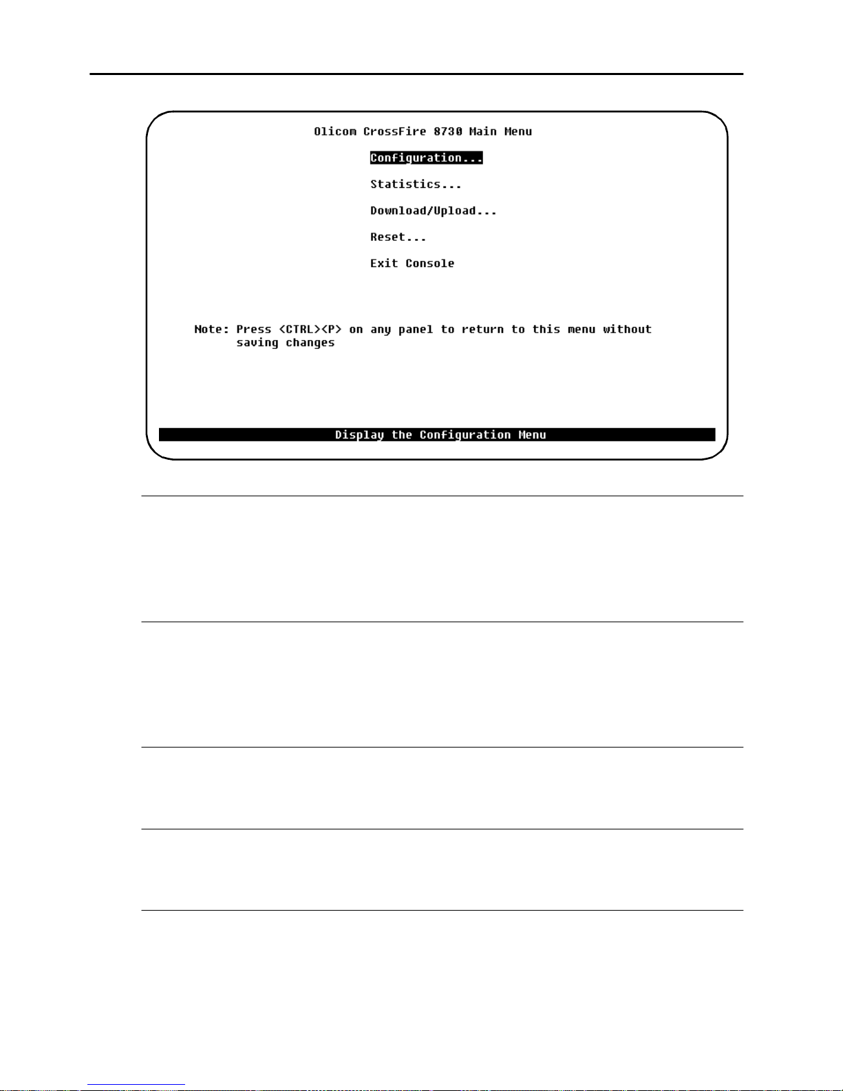
44
Main Menu
Configuration...
Displays the
configuration parameters. A detailed explanation of the configuration submenus
starts on on page 45.
Configuration
menu, which ena bles you to view and se t the switch
Statistics...
Displays the
Statistics
Menu” on page 135.
Statistics
menu are in Chapte r 4, “Monit oring the Network from the Statistics
menu for the switch. Exp lanations of screens in the
Download/Upload...
Displays the
Download/Upload
menu that is explained starting from page 125.
Reset...
Displays the
Reset
menu that is explained in this chapter starting from page 130.
Exit Console
Highlighting this command and pressing
greeting scr een (on a Telnet session, this will cause the se ssion to close) .
CrossFire 8730 Switch Reference Guide, DOC-7047 v. 1.1 Switch Configuration
ENTER
will return the console to the
Page 59
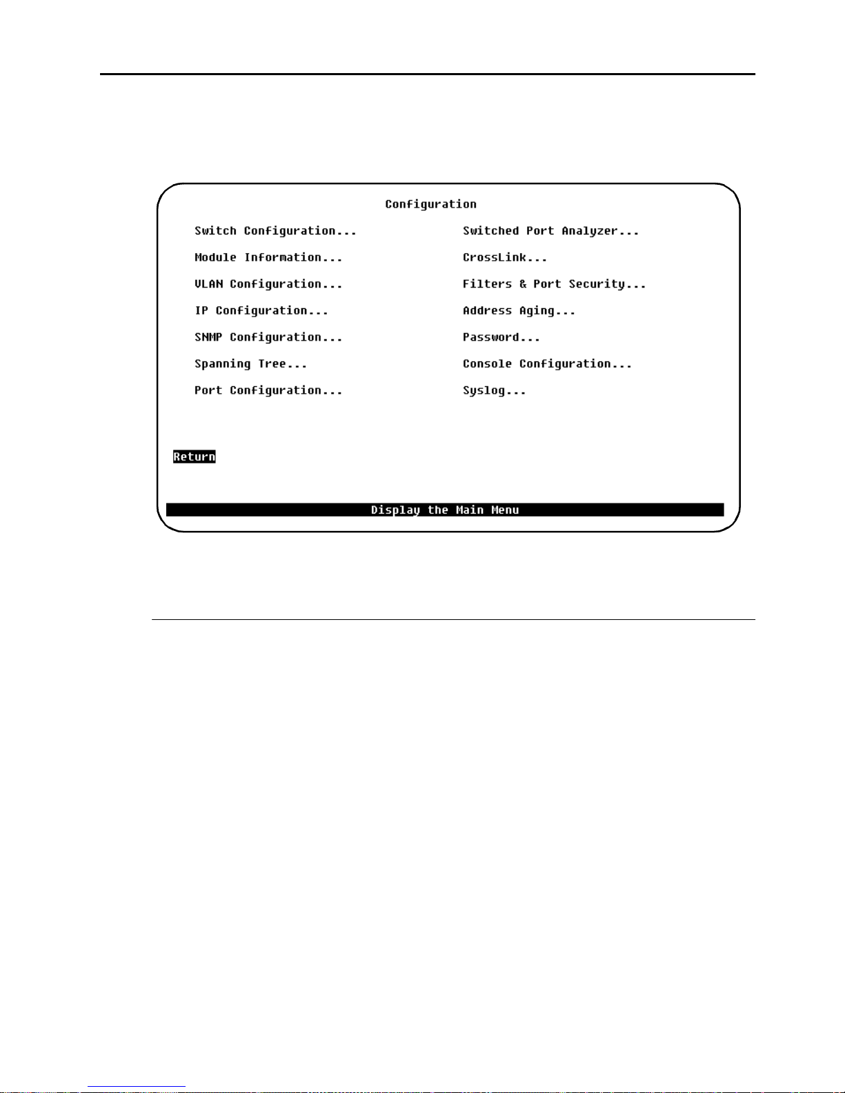
Configuration Menu
45
Open this menu by selectiong
From the
parameters.
Configuration
menu you can view and set the switch conf iguration
Configuration...
in the main menu.
Detail ed descriptio ns and of the submenus and screens these items open follows
below in thi s chapte r .
Configuration Overview for the Fast Ethernet Ports
To configure the Fast Ethernet ports, follow general steps lis ted below:
•
Determine wh ich VLANs the Fa st Etherne t ports should connect.
•
Determine which VLAN, if any, should be untagged.
•
Configure the Fast Et hernet VLAN ID for all the BRFs that should be tagged.
•
Make sure that each Fast Ethernet VLAN ID matches that of the Fast Ethernet
equipment in the other end.
•
Assign CRFs t o the Fa st Ethernet port, the reby creating one virtua l port in e ach
VLAN. Possibly cre ate new CRFs to make sure that the CRFs do not have
conflicting ring numbers, as discuss ed in s ection “Ring Number Restriction”
above.
•
Configure the virtua l ports, in particular the tagging mode. The relevant
configuration menus are described in detail in the following sections.
Configure the translational bridging parameters for each Virtual Port.
CrossFire 8 730 Switch R ef erence Guide, DOC-7047 v. 1.1 Switch Configuratio n
Page 60
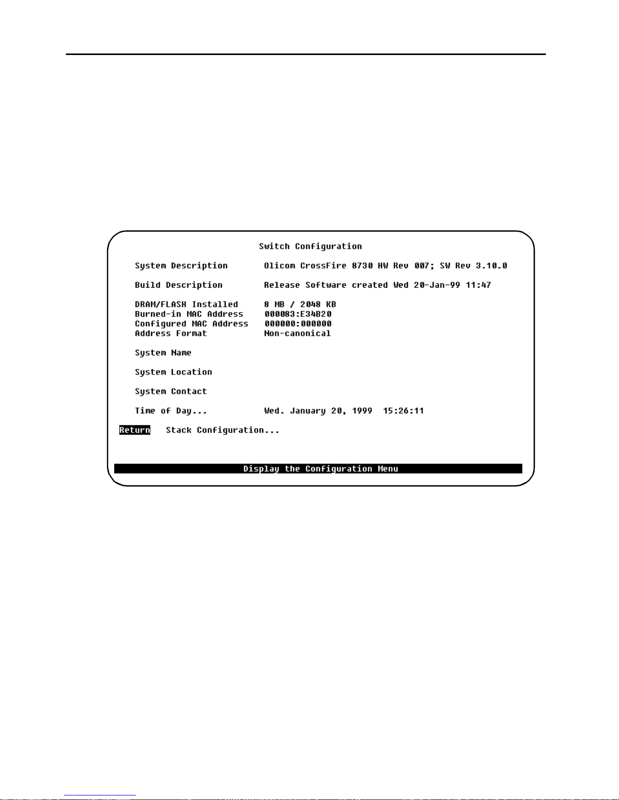
46
Switch Configuration Screen
To open this screen from the main menu, select
Configuration
.
Configuration
→
Switch
Use th is scr een to v iew sys tem inf orma tion a nd to vi ew or ch ange th e sys tem nam e,
location, contact, an d tim e of da y. To add or cha nge the system name, location,
contact or ti me of day, use the arrow ke ys to highl ight the fie ld and press the
ENTER
key. A prompt a ppears ne ar the bo tto m of the screen fo r entering t ext for that field.
Pressing
ENTER
again enters that text.
The following se ctions explain the fields in the
System Description
Name and model of this switch. Information in this field cannot be chan ged.
Burned-in MAC Address
The factory-assigned base MAC address of the switch. Information in this fie ld
cannot be changed.
Configured MAC Address
The MAC address that is current ly in use, or, if a new MAC address has been
configured, the MAC addr es s that will be used after the next boot. If a locally
administered addres s is assigned to the switch, this field displays that address.
Otherwise, the field displays
address, se lect this field, and enter the new address. Note that the switch occupies
this, the base MAC address, and the next 96 addres ses.
CrossFire 8730 Switch Reference Guide, DOC-7047 v. 1.1 Switch Configuration
000000:000000
Switch Configuration
screen.
. To assign a locally administered
Page 61

47
All usage of MAC-Addr esses in t he switch i s based u pon one addr ess. Thi s address
is denoted the Switch Ba se address and can be either Burned-in (The factory
assigned Universal Administrate d Addres s UAA) or configured (the Local
Administrated Address LAA). To configure a LAA address, use the
Configuration
Note that a restart is necessary when changing the base MAC address.
The greeting screen on the console will always show the current active Switch base
Address.
The switch reserves 31 addre sse s for ports.
The Token-Ring ports on a switch wil l be assigned MAC addresses using the
foll owing scheme:
•
BASE Modul e por t 1- 20 will be assigne d Swit ch Base Address + port n umber
OR:
screen fro m a console s ession or an SNMP based manageme nt tool.
Switch
•
A Token-Ring port will b e assigned a MAC address, which is Switch Bas e
Address + the port number displayed on the port conf iguration screen (or
interface table for SNMP).
This MAC address is used for the Token-Ring MAC protocol, and for the
spanning tree protocol.
The switch reserves 63 addresses for TrBRF ( VLAN).
Each VLAN has an attached Bridge relay function (TrBRF) and a Management
entity (IP-protoc ol stack), and conseque ntly it n eeds a MAC Address. In the s witch,
these two logical units u se the same address, however this address must be unique
in the netwo r k. This is ensured by assigni ng MAC addre ss to TrBRF’s from the
Switch Base Addre ss + 32 (0x20) and upwards. The switch is designed in such a
way, that it operates with 63 ac tive or preferre d VLAN’s, implying that 63 MAC
addresses need to be reserved for TrBRF.
Summarizing, each CrossFire 8730 reserve: Swit ch Ba se Address + 31 Addresse s
for Token-Ri ng ports + 63 MAC Addresses for T rBRFs = 95, which is rounded up
to 96 or hexadecimal 0x60.
The MAC a ddress of the de fault TrBRF (brf -def ault) will alway s be the switch base
address + 32. If the s witch opera tes in a st ack, only o ne of the switc he s wil l opera te
the bri dge re lay functi on. He nce t he MAC addre ss of the defaul t TrBRF wil l be the
base address of the stackmaster + 32. The stackmaster is determined by software,
when the stack consists of two switches back to back and by the port numbers in
8300/8635 stack configurations.
There is no simp le rule to find the MAC address of other TrBRF, but it is alwa ys
within the range described, as fol lows :
CrossFire 8 730 Switch R ef erence Guide, DOC-7047 v. 1.1 Switch Configuratio n
Page 62

48
•
Stack Ma ster Ba se Add ress + 32 < TrBRF MAC Addres s < Sta ck Maste r B ase
Addr ess + 95 .
A TrBRF (VLAN) MAC address is assigned, when the VLAN becomes
preferred (i.e. it has an ass igned port in the ac tual switch or stack of switches)
by selecting the lowest available MAC address above Stack Master Base
Addr ess + 32 .
If management (SNMP or TELNET) contact with the switch is lost (e.g. becaus e
ports are moved from one TrBRF to another) it is suggested, that a terminal is
connected to the OBM port of the switc h st ac k, and the IP Configuration menu is
entered. F rom here, it is possible to read the MAC address of the mana gement entity
(TrBRF).
Address Format
Display form at used for MAC addresses (canonical or non-canonica l). Canonical
format is typi call y used in Etherne t networ ks and is al so kno wn as le ast sig nif i cant
bit firs t. Non-ca nonical is t ypically us ed in T ok en-Ri ng networks and is also kno wn
as most signi ficant bit first.
System Name
Any name you c hoose to assign to t he swi tch (on a TCP/ IP net work, it c ould be the
IP hostname).
System Location
Physical location of the swi tch.
System Contact
Person to contact if questions should a rise.
DRAM Installed
Amount (i n MB) of dynamic memory installed. Information in this field cannot be
changed.
Flash Memory Installed
Amount (in KB) of flash memory installed. Information in this field cannot be changed.
CrossFire 8730 Switch Reference Guide, DOC-7047 v. 1.1 Switch Configuration
Page 63
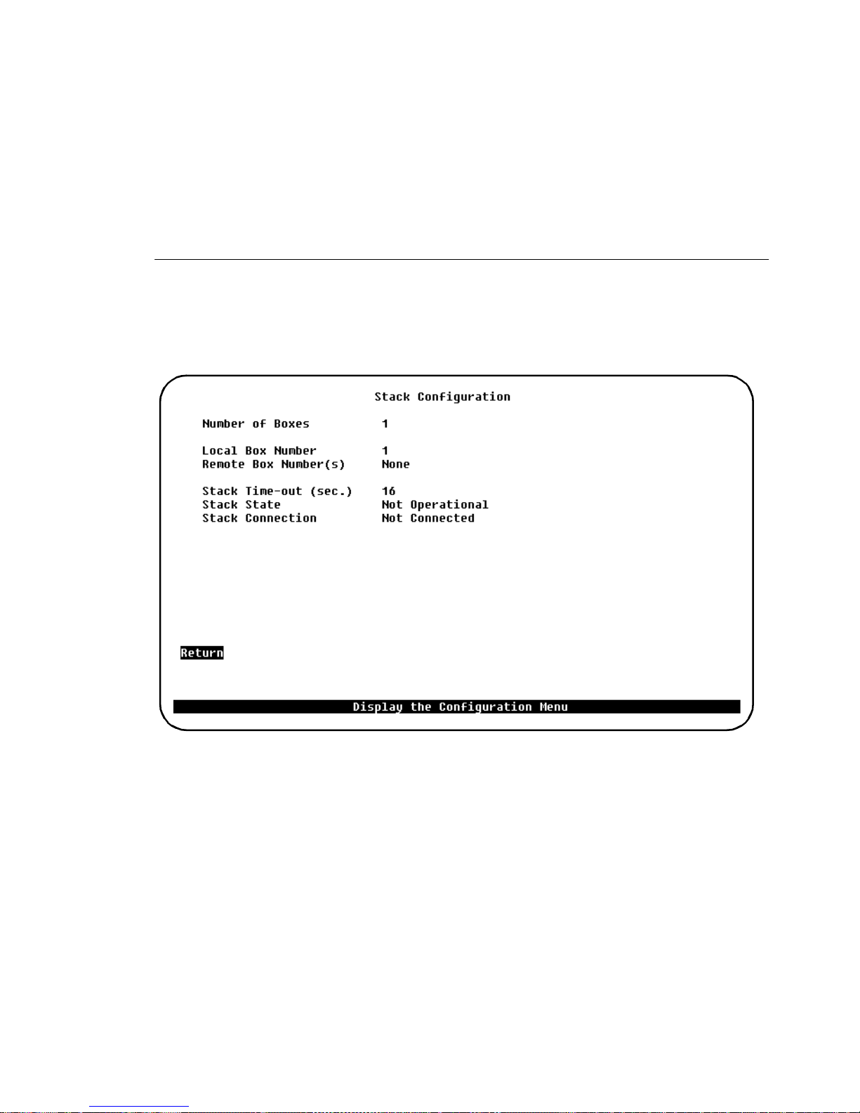
Time of Day
An internal clock is used to cal culate total time of operation and time of day. To
adjust the time, select this item, press
ENTER
, then enter the month, day, hour, or
minute.
49
➽ Note:
this is the case, contact your local reseller.
Stack Configuration Screen
To open this screen from the main menu, selec t
Configuration
If you c ann ot se t the
Stack Configuration
→
Time of Day
, the lithiu m battery may need replacin g. If
Configuration
→
Switch
.
The following information is displayed on this scre en:
Number of Boxes
Number of switch es currently participating in the stack. Information in this field
cannot be chan ged.
Local Box Number
Number a ssigned to the switch to which the console is connected. T he local box is
also the s ource of the inform ation displa yed on this screen. Info rmation in t his field
cannot be chan ged.
CrossFire 8 730 Switch R ef erence Guide, DOC-7047 v. 1.1 Switch Configuratio n
Page 64
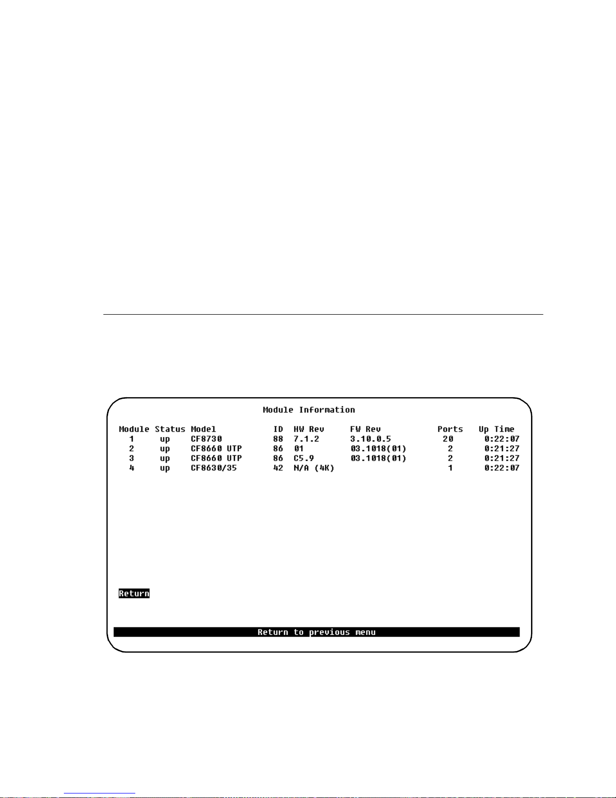
50
Remote Box Number(s)
Number of switche s (in addition to thi s one) in the stack. Information in this field
cannot be changed.
Stack Time-out
If a switch goes off line, the length of ti me (in seconds) duri ng which the stack tr ies
to reesta blish communication with the switc h. The default is 16 seconds.
Stack State
Whether t he CrossFi re Switc h Sta cker is oper ationa l (Cro ssFir e 8630 or CrossF ire
8635). Information in thi s field cannot be changed.
Stack Connection
Whether th e CrossFire 8300 Switch Stacker is connected. Inf ormation in this fie ld
cannot be changed.
Module Information Screen
To open this screen from the main menu, select
Information
.
Configuration
→
Module
This scree n shows informati on a bout the di fferent module s tha t the swi tch consis ts
of:
CrossFire 8730 Switch Reference Guide, DOC-7047 v. 1.1 Switch Configuration
Page 65

51
Module
Module num ber. The b asic swit ch is list ed as modu le 1. The Fast E therne t ports 21
and 22 are li sted a s module 2 and por ts 25 and 26 a re li sted as module 3. The stack
port is listed as module 4.
Status
Whether the modul e is up, down, or the slot is empty.
Model
Type o f modu le. The Cros sF ire s wit ch is li ste d f or t he ba s e s witch. For t his module
as well as for others, this field displays the product num ber.
Board ID
Identifi er of the board in decimal.
HW Rev
Hardware revision leve l.
FW Rev
Firmware revis ion level. On modules with Token-Ring ports, this is the MAC mode
revisi on level.
Ports
Number of ports on the module.
Up Time
Amount of time (i n hours, m inutes, a nd second s) that th e module has been up (since
the last reset).
You cannot change the information that appears on this screen.
CrossFire 8 730 Switch R ef erence Guide, DOC-7047 v. 1.1 Switch Configuratio n
Page 66
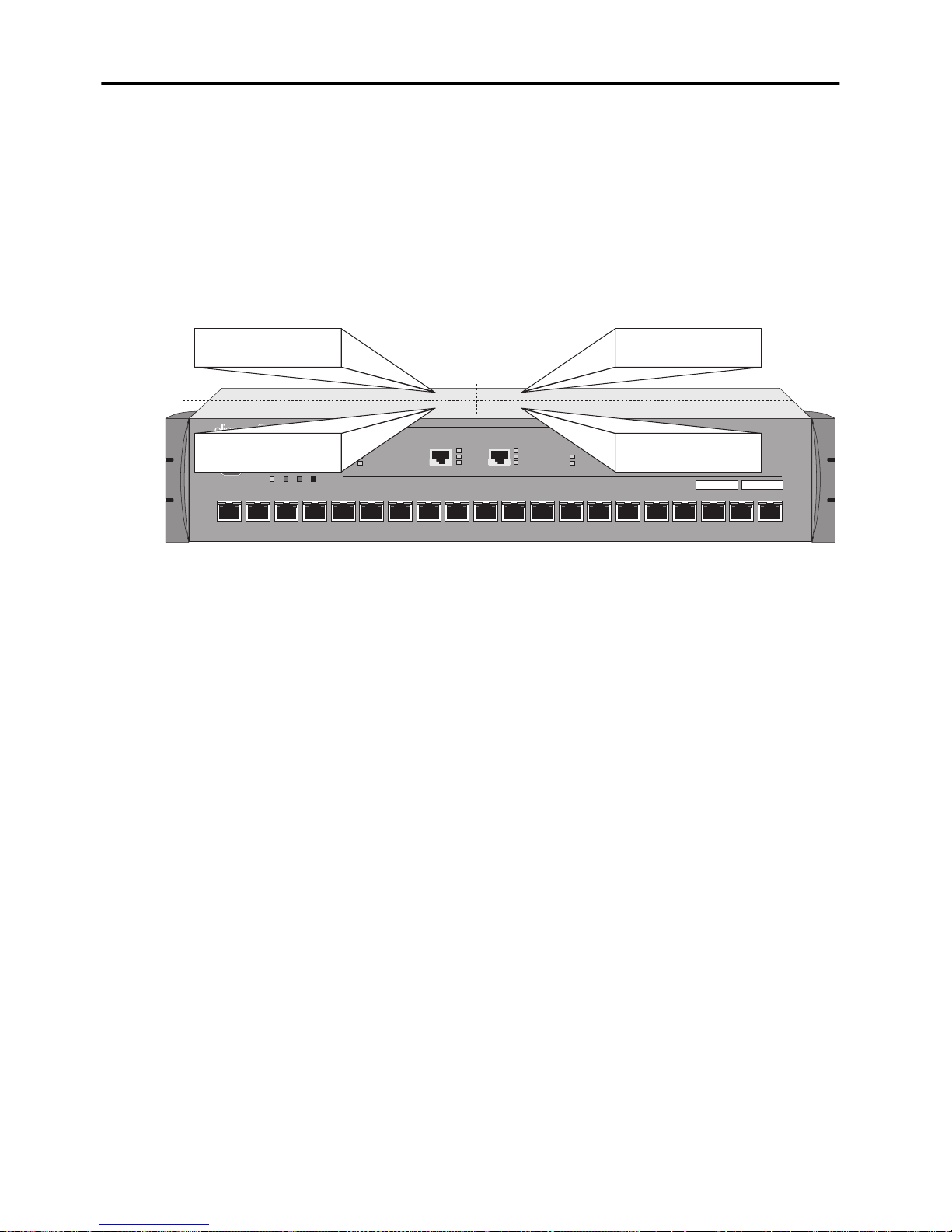
52
VLAN Configuration
The Virt ual LAN featur e can be used to pa rtitio n a swit ch or a sta ck of swi tches i nto
several Virtual LANs, each containing its own set of ports (the ter ms
and
domain
belonging to the same. The benefit of Virtual LAN is to restrict access from one
segment to another, either for s ec urity purposes or to reduce interse gm ent traffic.
Figure 15 illustrates a switch with four VLANs.
are interchange able). Packets are forwarded only between ports
Virtual LAN
VLAN 1
Ports 1, 2, 3, 10
VLAN 3
Ports 4, 7, 9
STACK-LINK
ATTACH
RXTX
DIAGPWR RSTERRMANAGEMENT
1
32
STATUS
FAULT
21-22 25-2622 2625
5
4
21
876109
ACT
100
LINK
ACT
100
LINK
FASTETHERNET
STATUS
FAULT
VLAN 2
Ports 5, 11, 12
CrossFire 8730
VLAN 4
Ports 6, 8, 13, 14
151211 1413 1716
Fast Ethernet Translation Switch
ACT
100
LINK
ACT
100
LINK
18 20
19
Figure 15. Switch with Four VLANs
To set up domains using the VLAN Configuration menu, specify the port s
belonging to the domain s, then set up the IP configura tions, tr ap configur ation (tra p
receivers are associated with a set of VLANs and a receiver IP address) and STP
configurations specific to the appropriate VLANs. If you have already supplied
configuration information using the main configuration menus, that information
applies to VLAN “default”. Virtual LANs affects other switch feature s in the
following ways:
•
Spanning Tree Protocol (STP).
must supply STP information for that domain. The STP software treats ports
on other dom ains as none xistent . Domains do not affect port priorit ies and por t
costs. You set these parameters us ing the STP Configuration menu that you
select from the main Configuration menu.
•
SNMP trap tables.
as a physically different Token-Ring switch unit. Certain MIB II objects and
proprietary objects are domain-sensitive, while others are not. For a list of
domain-se nsitive objects , see Chapter 4, “Monitor ing the Network from the
Statistics Menu”.
•
You may give each domain an IP addres s, subnet mask, and gat eway
IP.
address definition.
CrossFire 8730 Switch Reference Guide, DOC-7047 v. 1.1 Switch Configuration
If you are using STP in a certain domain, you
Each domain appear s to the network management system
Page 67
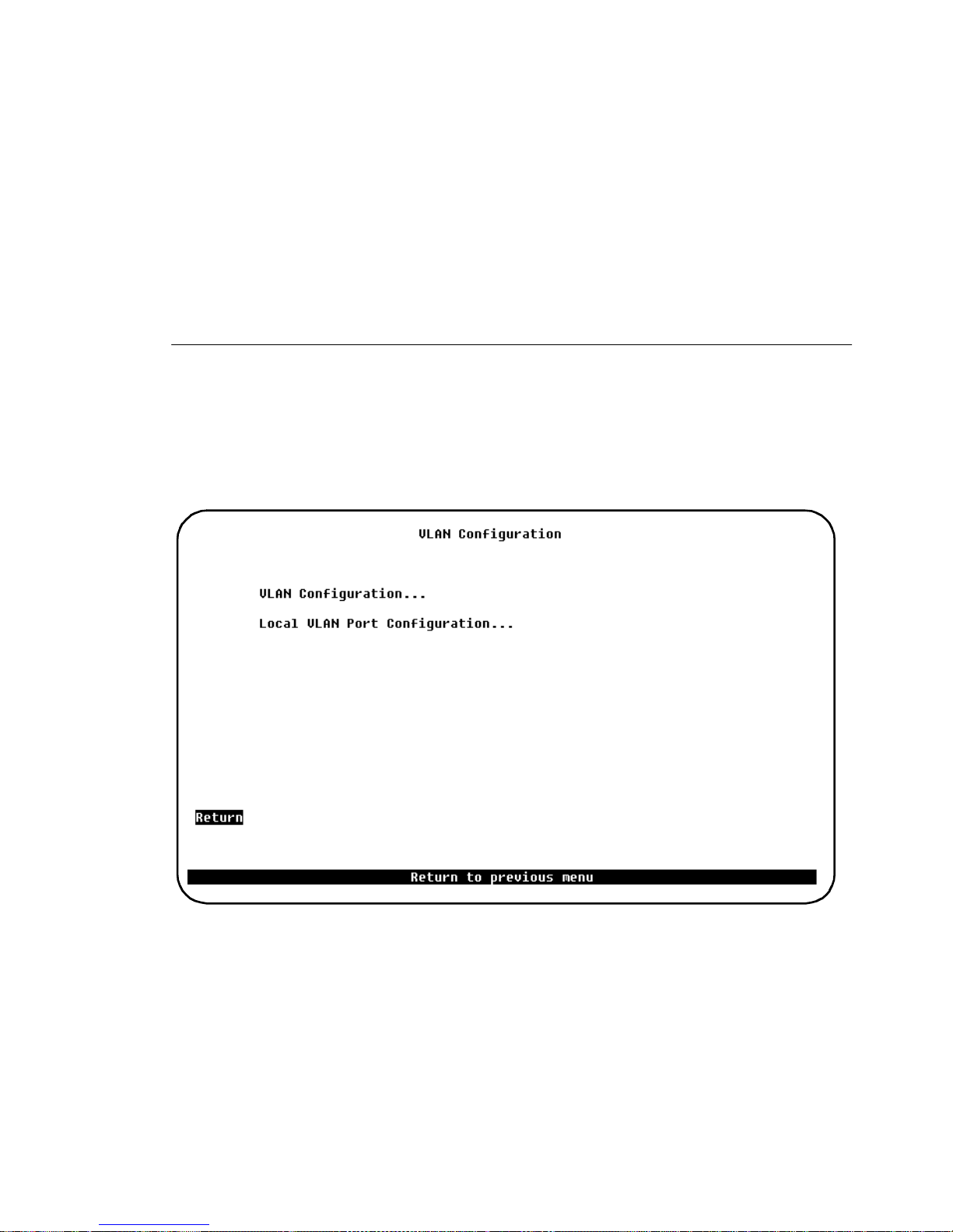
53
•
Address filters.
suppose you cre ate two domains: one conta ining port s 1–8 and th e oth er ports
9–16. If you add an address filter to ports 7, 8, 9, and 10, the filter will work
properly even though it a pplies to ports in other domains.
•
Cros sLink.
same CRF. Therefore, the console software prevents you from defining a
CrossLink connection tha t includes ports in different CRFs. I t also prevents
you from assig ning the Token-Ri ng ports i n an ex isti ng Cros sLink t o different
CRFs.
Domai ns have no effect o n add r ess filters . For exam pl e,
All the Token-Ring ports in a single C r ossLink must belong to the
VLAN Configuration Menu
To open this screen from the main menu, selec t
Configuration.
See the section “VLAN Support” on page 35 for a discussion of VLANs.
Configuration
→
VLAN
Information on the various submenus follows in the next two subsect ions.
CrossFire 8 730 Switch R ef erence Guide, DOC-7047 v. 1.1 Switch Configuratio n
Page 68
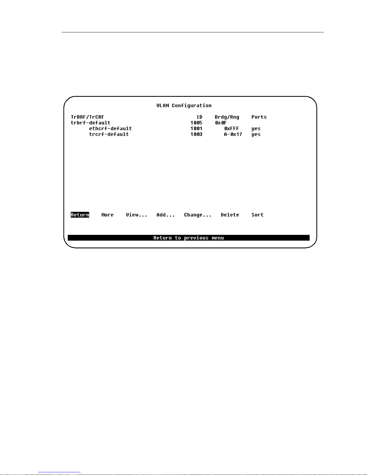
54
VLAN Configuration Screen
To open this screen from the main menu, select
Configuration
VLAN Configuration.
→
Configuration
→
VLAN
Use the this screen to define and administer BRFs and CRFs in the switch.
TrBRF/TrCRF
ASCII na me associated with the BRF or CRF.
ID
Numeric ID.
Brdg/Rng
Bridge/Ring numbers.
Ports
Port numbers.
Return
Returns to the previous menu.
More
Scrolls or refreshes the display.
View...
Zooms in a VLAN.
CrossFire 8730 Switch Reference Guide, DOC-7047 v. 1.1 Switch Configuration
Page 69
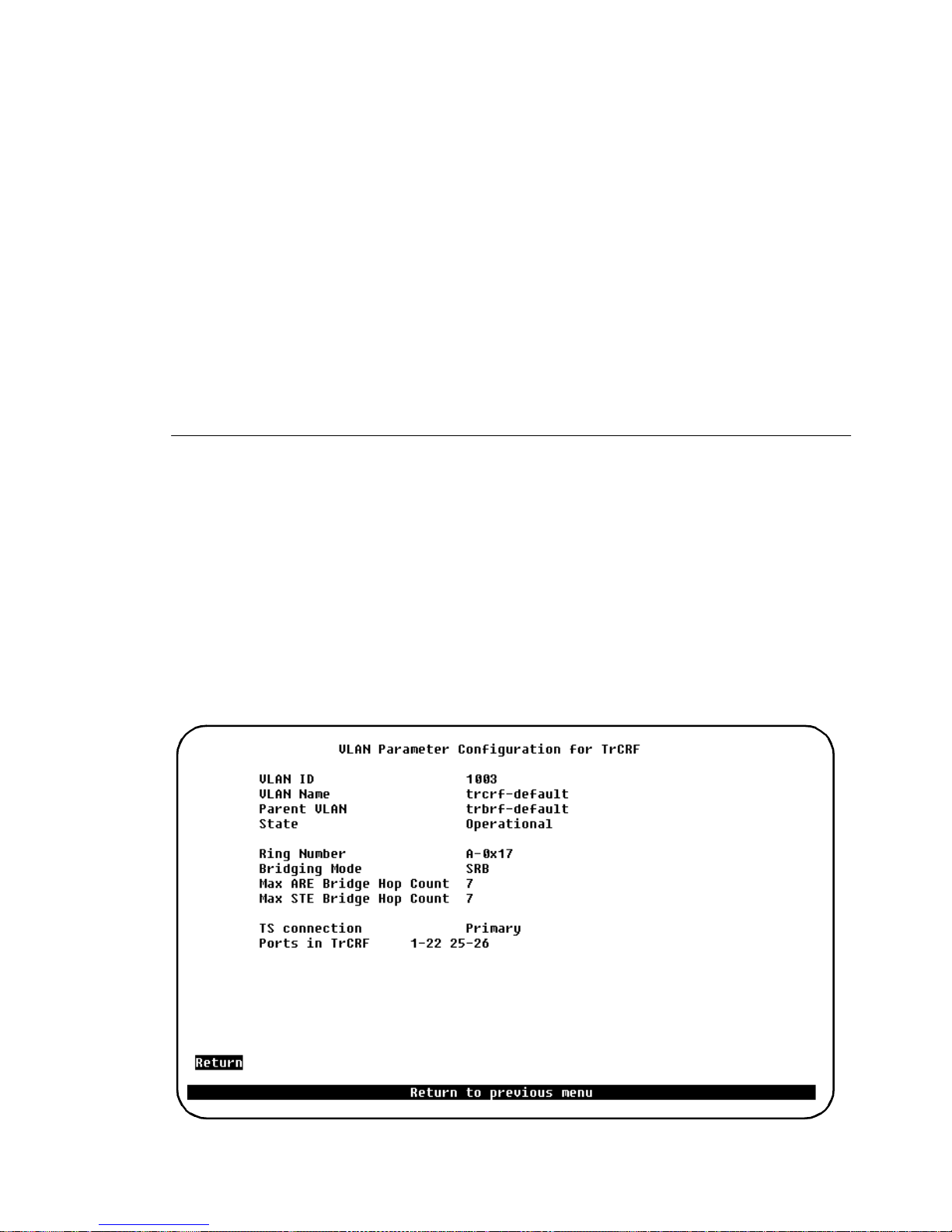
Add...
55
Prompts for a new ID and brings up the
VLAN Parameter Configuration
screen.
Change...
Prompts for a numeric ID of a BRF or CRF to change and brings up the
Param et e r C o nf ig u r ati o n
screen.
VLAN
Delete
Lets you de lete a BRF or CRF. You canno t delete a BRF if there are CRFs as signed
to it, or a CRF if there are ports assigned to it.
Sort
Sorts VLANs by Parent-Child relationship, or by VLAN-ID.
VLAN Parameter Configuration for TrCRF Screen
To open this screen, do the follo wing:
1. From the main menu, se lect
VLAN Configuration.
Configuration
VLAN Configuration
→
→
2. Select
View..., Add...,
or
Change...
3. When prompted, enter the VLAN ID for the TrCRF.
Use this screen to add or change a CRF. Note that the
deleted. Also, the
trcrf-default
cannot be assigned to other BRFs.
trcrf- default
cannot be
The follo wing information is displayed on this screen:
CrossFire 8 730 Switch R ef erence Guide, DOC-7047 v. 1.1 Switch Configuratio n
Page 70

56
VLAN ID
Numeric ID of the CRF. Possible values ar e 1 through
and 1 are reserved for the default CRFs and BRFs.
1005
1005
. Values
1002
through
VLAN Name
ASCII name associated with the CRF. Up to 32 characters are allowed.
Parent VLAN
Parent to which the CRF belongs.
State
Curren t sta te of th e CR F. Pos s ibl e va lu es ar e
Operational
and
Suspended
. CRFs in
operational state ar e func tional. CRFs in suspended state do not pass pac kets. The
default is operational.
Ring Number
Logical r ing number assigned to this CRF. Possible hexadecimal v alues are
and
OX001
through
OXFFF
. The d efault is
, meaning t hat the rin g number will
auto
auto
be learned. If the ring number has been learned, the learned ring number will be
prefixed with A.
➽ Note:
CRFs know their ring numbers. If you are running the switch in an environment
without other bridges/switches, learning of ring numbers is not possible. Hence
manual configuration of ring numbers is r equired.
Bridging Mode
Bridging m ode for this CRF. P ossible values are
Max ARE Bridge Hop Count
Maximum number of hops for all-routes explorer (ARE) fram es. Possible values
are 1 through 13. The default is 7.
Max STE Bridge Hop Count
Maximum number of hops for spanning tree explorer (S TE) frames. Possible
valu es ar e 1 through
TS Connection
This parameter displays the connection attribute assigned to the selected CRF of
Fast Etherne t ports that are connected to the Ethernet cloud. The connection
attribute can be one of the following:
Forwarding of frames between CRFs in SRB mode is only possible, if the
The default is 7.
13.
SRB
and
. The default is
SRT
SRB
.
•
Primary
connection - for a main connection to the Ethernet cloud (default
value for each CRF). This connection is always forwarding if active.
CrossFire 8730 Switch Reference Guide, DOC-7047 v. 1.1 Switch Configuration
Page 71
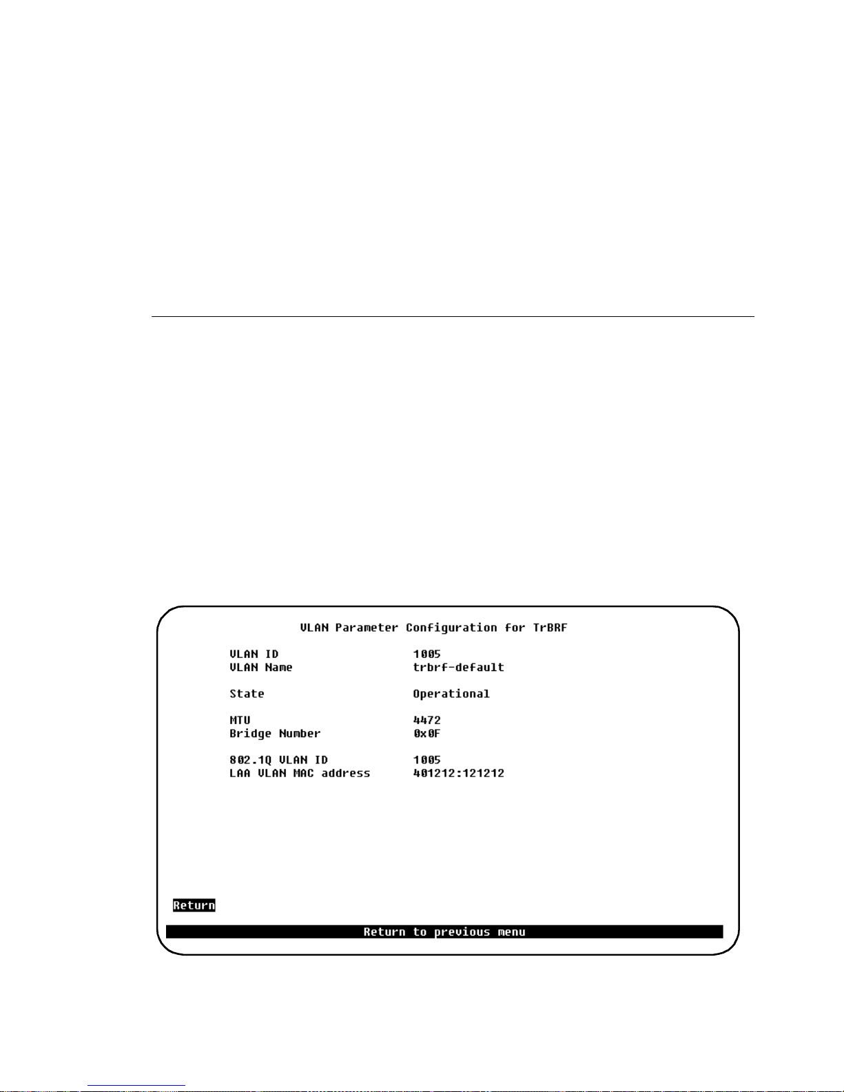
57
•
Secondary 1
is always blocking if
•
Secondary 2
connection is always blocking if
Each CRF of Fast Ethernet ports connected to the same Ethernet cloud must have
a different connection attribute set.
Ports in TrCRF
This parameter lists the ports assigned to the CRF.
- for a bac kup connection to the Ethernet cloud. This connection
Primary
- for a second backup connection to the Ethernet cloud. This
is active.
Primary
or
Secondary 1
are act ive.
VLAN Parameter Configuration for TrBRF Screen
To open this screen, do the follo wing:
1. From the main menu, se lect
VLAN Configuration.
2. Select
View..., Add...
or
Change...
Configuration
VLAN Configuration
→
→
3. When prompted, enter the VLAN ID for the TrBRF.
Use the this screen to add or chang e a BRF . Note that the
deleted. Also, the
shown be l ow.
trbrf-default
cannot be assigned new BRFs. The BRF screen is
trbrf- def ault
cannot be
The follo wing information is displayed on this screen:
CrossFire 8 730 Switch R ef erence Guide, DOC-7047 v. 1.1 Switch Configuratio n
Page 72

58
VLAN ID
Numeric ID of the BRF. Po ssible value s are 1 through
and 1 are reserved for the default BRFs and CRFs.
1005
1005
. Values
1002
through
VLAN Name
ASCII name associated with the BRF. Up to 32 ch aracters are allowed.
State
Current state of the BRF. Possibl e value s are Operatio nal and Suspen ded. BRF s in
operational state ar e func tional. BRFs in suspended state do not pass pac kets. The
default is operational.
MTU
Maximum Transfer Unit of the BRF (maximum size of the information field in
transm it ted pa cke ts) . P ossi bl e valu es a re
1,500, 4,472
(defau lt) ,
8,144
, and
17,800
The actual value used depends als o on the va lue configur ed for th e port (the sm aller
value is used).
These valu es correspond to maximum frame size values of
9,236
, and
18,192
resp ectively.
1,548, 4,546
(default),
.
The actual value used depends on the value configu r ed for the ports (the smaller
value is used).
Bridge Number
Source-routing bridge number for this BRF. Possible hexadecimal va lues are
0
through F. The default is F.
802.1Q VLAN ID
The 802.1Q VLAN ID is the value that is inserted in the IEEE 802.1Q frame tags.
It is entered as a decimal value betwe en 1 and 4094.
The 802.1Q VLAN ID s hould not be confused with the exist ing VLAN ID, which
is a number chosen by the user and used by the switch to index CRF s and BRFs.
By default, however, the 802.1Q VLAN ID is set to the same value as the VLAN
ID.
LAA VLAN MAC Address
This paramete r makes it possible to as sign an Local Administrated Address used
for IP communication to the selected VLAN. You will have to reset the switc h
before the n ew value ta kes effect. The selected v alue is only u sed for IP (and SNMP
over MAC), not for Spanning Tree.
CrossFire 8730 Switch Reference Guide, DOC-7047 v. 1.1 Switch Configuration
Page 73
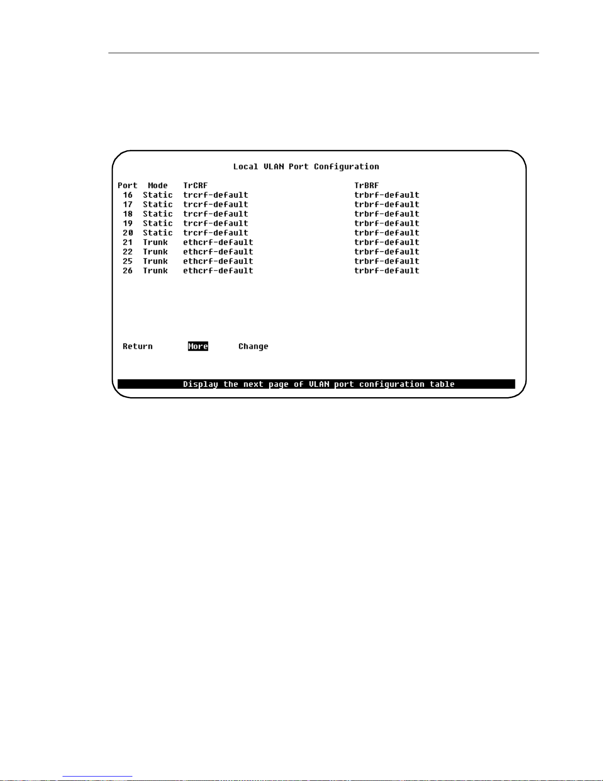
Local VLAN Port Configuration Screen
59
To open this screen from the main menu, selec t
Configuration
Local VLAN Port Configuration.
→
Configuration
→
VLAN
Thi s s creen is used to view and ed it current port assignmen t s to CRFs.
Port
The port number.
Mode
VLAN mode of the port. Possible values are
Static
The Fast Ethernet ports will appear as trunk ports in the
Configuration
. This means that more than one CRF can be assigned to the Fast
and
Trunk
.
Local VLAN Port
Ethernet port s. Note, however, the virtual port restriction described above.
TrCRF
CRF to which the port is currently assigned. By default, all ports are assigned to
trcrf-default.
TrBRF
Parent BRF of the CRF to which the port is currently assigned. The default is
trbrf-default
.
CrossFire 8 730 Switch R ef erence Guide, DOC-7047 v. 1.1 Switch Configuratio n
Page 74
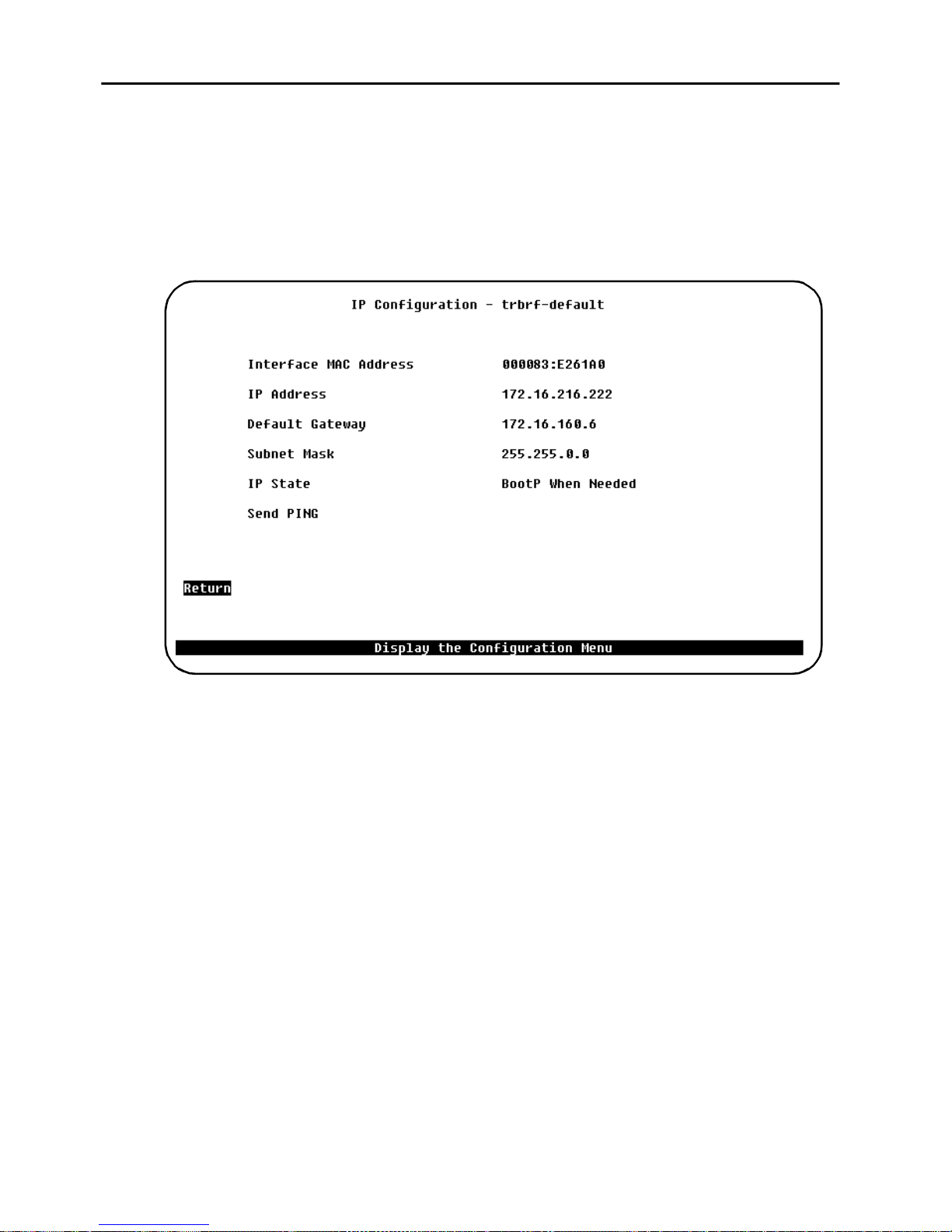
60
IP Configuration Screen
To open this screen from the main menu, select
IP Configuration.
Then select the TrBRF to display the screen.
Configuration
→
This sc r een is used to view or change IP information as sociated with a BRF, suc h
as the IP address, subnet mask, or IP state, or to send PINGs.
Interface MAC Address
Displays the MAC address assigned to this BRF.
IP Address
Displays the curre n t IP address of the sel ected TrBRF. To change it, highlight the
field and press
Default:
192.0.2.1
ENTER
.
Default Gateway
Displays the current gateway address. The default is the IP address of the gateway
or router through which information must pass to get to the network management
applica tion.
Default:
0.0.0.0
Subnet Mask
Displays the curre nt subnet mask.
Default:
0.0.0.0
CrossFire 8730 Switch Reference Guide, DOC-7047 v. 1.1 Switch Configuration
Page 75

IP Sta t e
61
Display the following choices by highlighting
•
•
•
Then hig hli ght one o f the se c hoice s and p ress
are as descri bed be low:
•
➽ Note:
0.0.0. 0
•
IP State
IP Disabled
BootP When Needed
BootP Al w a ys
ENTER
IP Disabled
packets it receives. This means that no IP-SNMP , Ping, Telnet, or ARP Packets
will be responded to when received.
Sending a Pin g from an IP-disabled VLAN or a VLAN whose IP a ddress is
is not possible.
BootP When Needed
the V LA N u nt i l th e IP ad dress beco mes differ e nt fro m
BootP When Needed
not initialized (for instance, a new switch out of the box or on a bootup after
NVRAM is cleared) or one whose NVRAM is corrupt ed and unreadable, will
always attempt to use BootP the first time.
—When a VLAN is IP -dis abled , it will not pro cess an y IP o r ARP
—In this stat e, the switc h will s end out Boot P r equests in
is the fa ctory-s et de fault . A swi tch for which NVRAM is
and pressing
. The meaning of these values
0.0.0.0
ENTER
or
192.0.2.1
:
.
•
➽ Note:
VLANs the de f au lt is
Send PING
Prompts you to ent er an IP addr es s (I P address must be entered and the IP subn et
mask must be s et). The system then sends a PING to that address. No te that if you
have ju st set th e IP address, you must pre ss
a PING can be sent.
BootP Always
fully on boot unt il a BootP repl y has be en recei v e d. If a non-z ero IP addre ss is
stored in NVRAM for a g i v en VLAN in t his sta te when booted, it is clea red to
0.0.0.0
For the default TrBRF the value is
since it would never be used.
—In this stat e, IP is enable d for the VLAN b ut will not f unct ion
. For all the other
IP Disabled
BootP wh en Ne ed e d
ENTER
and select the menu again before
CrossFire 8 730 Switch R ef erence Guide, DOC-7047 v. 1.1 Switch Configuratio n
Page 76

62
BootP Requ ests and Parameters
When using Boot P to de term ine i ts IP a ddress, t he s witch repea ts BootP reque sts a t
regular intervals, beginning at one second each and eventually decreasing to every
five minutes ove r time until it receives a valid reply. If the IP display for th e VLAN
is accessed from the console (or via Telnet from another VLAN) during that tim e,
the switch may cease usi ng BootP if the parameters ar e set (on display exit) in such
a way that BootP would no longer be necessary - for instance, if the IP state is
switched from
0.0.0.0
Once the switc h has stopped send ing BootP requests on a VLAN, it does not restart
sending requests on that VLAN and does not recognize BootP responses on that
VLAN unless the switch is reset.
Besides the switch's IP address, several other parameters in a BootP response are
also recognized and recorded in NVRAM, when received in the same re sponse:
or
BootP Always
192.0.2.1
is specifie d in an y I P s ta te.
to
IP-Disabled
or if an IP address different from
•
•
•
•
One other para meter, the TFTP VLAN, is infer red whenever a TFTP Bootfile name
is present in the BootP response. That is, if the switch receives a Boot P response
that specifies a TF TP Bootfile name, the s witch automatically records the VLAN
on which the respons e was received as the TFTP VLAN number. Therefore, the
bootfile name should not be specified on a VLAN from which the TFTP server
cannot be accessed, either directly or through the VLAN’s default gateway (if one
exists). More information on TFTP is available under the section "TFT P " on page
127 in th i s ch ap ter.
➽ Note:
subnet address is the same as that of the IP addre ss specified. If no route rs are
specified or if none qualify, the gatew ay ad dres s for the VLAN will be zeroed out
and re co rd ed as su ch in NVRAM w h en th e IP sc reen is exit ed .
Default Gateway (see note below)
Subnet Mas k
TFTP Bootfile Name
TFTP Server Address (only recognized if the Bootfile nam e is present)
The default gateway accepted is the first one in the list of routers whose net/
CrossFire 8730 Switch Reference Guide, DOC-7047 v. 1.1 Switch Configuration
Page 77

SNMP Configuration Menu
63
The next menu item in the
Configuration
menu is
SNMP Configuration..
.
This item opens a menu that is e xplained in Chapter 5, “Monitoring the Network
with SNMP”.
The next secti on describes the Spanning Tr ee Protocol and th e STP menus that you
can acce s s fro m the
Configuration
menu.
CrossFire 8 730 Switch R ef erence Guide, DOC-7047 v. 1.1 Switch Configuratio n
Page 78

64
Spanning Tree Prot oc ol
The spanning tree protocol (S TP) is a bridge-to-br idge link management protocol
that provid es path redunda ncy while pre venting unde sirable loops . To provide pat h
redundanc y, spanning tree protocol de fines a tree that spans all switches and
bridges in the e xtended network. If one of the ne twork segments in the tre e becomes
inacce ssible , STP re configu res it self t o reestab lish t he links. To preven t loops , STP
selects just one swi tch port as the designated path to the root, assign ing it the
Forwardin g, or a ctiv e st ate. It assi gns a ll ot her port s t he bloc ki ng, or stan dby, s tate .
A port in the blocki ng state does not forwar d any tra nsmitted frames in any
direction.
➽ Note:
path cost, sel ect only the ports which are part of the current VLAN. Do not
configure ports in other VLANs.
The path cost indicates the r elative spe ed of the segment: The higher the speed of
the segment , the lower the path cost. Swit ches and bridges in the network at tempt
to determine the path to the route with the lowest path cost. IEEE 802.1D
recommends tha t you assign path costs us ing the following formula:
Path cost = 1000 / LAN spee d in Mbps
If two ports to the root have the same path cost, the STP device selects the one with
the highest priority (lowest value), an arbitrary value that you assign. To block
traffic on a particular segment, assign it low port priority (high value)
If more po rts have the same priorit y va lue a ssigned , the lowe st p ort number will be
selected.
IEEE 802.1D Spanning Tree Protocol (STP)
In the VLAN STP confi gurati on menu, f or the sele ction of por t pri orit y/po rt
When the IEEE 802.1D Spa nning Tree Prot ocol is a ctive, a port wi thin tha t domain
will require se veral seconds to make the transi tion from the blocking state to the
forwarding st ate, when the port is ini tially activated (e.g. joins an existing ring or
activates a dedicated link.) Some client or server applications may attempt to
establis h s es sion activity during this time, resulting in error messages indicating a
connection failure. These applications should be configured to wait at lea s t 30
seconds af ter the LAN link i s activ e, before att empting to esta blish ses sion activi ty.
This delay can be re duced by modifying the 802.1D Spannin g Tree Protocol defaul t
parameters.
If STP is ena ble d on a dedica te d port , and a stati on is at tac he d to it, it take s at le ast
30 seconds for the port to transi tion Down
Forwarding.
CrossFire 8730 Switch Reference Guide, DOC-7047 v. 1.1 Switch Configuration
→
Listening
→
Learning
→
Page 79
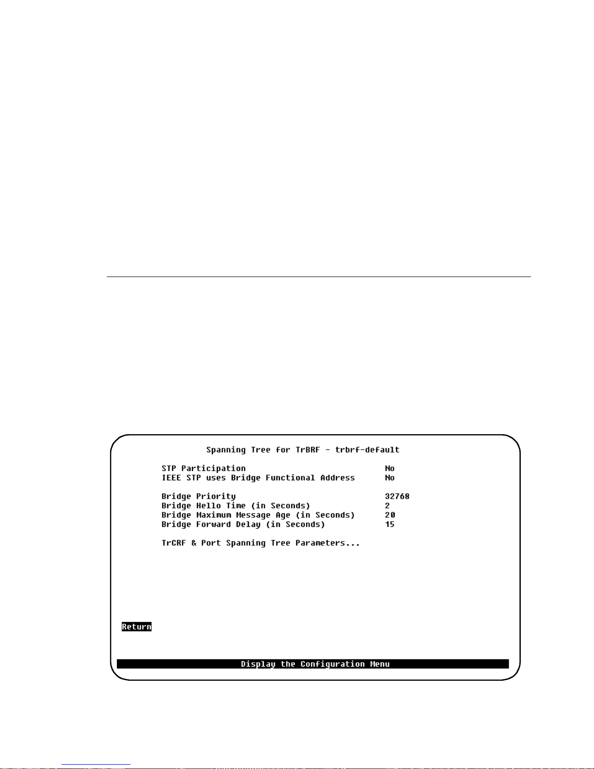
65
The IPX c lient and server stations may have given up before then. And the first
many PINGs get lost.
In general , STP should not be enabled on ports, which are intended for dedicated
stations. Shared media do not ha ve the same problem, because the port will stay
attached to the Hub, even though all sta tions have closed.
Another reason for not enabling STP on dedicated ports is, that th e whole network
will go into To pology Change state each time a station opens or closes. This will
cause the whole network to use short aging timers, so all address tables will be
trashed. The result is a lot of unknown station broadcasts, before the tables
converge again.
To disable STP on a port, select the STP Mode
Forwarding
for this port. Refer to
the “STP Mode ” pa r a mete r on page 71 .
Spanning Tree for TrBRF Screen
To open this screen from the main menu, do the fol lowing:
1. Select
Configuration
Spanning Tree. A
→
VLANs appears.
2. Choose a T rBRF from the l ist. The
Spanning T ree f or TrBRF
appear. From this screen you can go on to s elect TrCRF s and ports associated
with the BRF for modi ficati on (
T rCRF & Port Spanning T ree Parameters...
list containing available Tr BRF
screen will now
).
STP Participation
Whether this TrBRF participates in the spanning tree protocol and, if so, the
CrossFire 8 730 Switch R ef erence Guide, DOC-7047 v. 1.1 Switch Configuratio n
Page 80

66
protocol to be use d. Possible values are No,
. The default is No.
Mode
•
If
STP Participation
will be set to forwarding mode. You can then ove rride this by blocking a
particular TrCRF.
•
If
STP Participation
used to de termi ne th e fo rw ar d ing/b lo ck ed m o d e of th e TrCRFs that are
configured with an STP mode of
•
If
STP Participation
protocol us ed is based on the bridging mode of the TrCRF. If the bridging
mode is SRB, the IBM Spanning Tree Protocol is used. If the bridging mode
is SRT, the IEEE 802.1D Spanning Tree Protocol is used.
For a particula r TrCRF the pro tocols selec ted here ca n be overri dden. See the
Mode
IEEE STP Uses Bridge Functional Address
•
parameter in the section “Spanning Tree for TrCRF Screen” on page 67.
: Sets IEEE Spanning Tree to use the Bridge Functional Address.
Yes
is set to No, then all TrCRFs with this TrBRF as a parent
is set to
is set to
IEEE
auto
Base on Bridging Mode
IEEE, IBM
or
IBM
.
, then the sele cted prot ocol wil l be
, and
Base on Bridging
, then the spanning tree
STP
•
Bridge Priority
Enter a priority value for this switch. The bridge with the lowest priority value in
an STP becomes the root. (To change individual port priorities, enter the
Spanning Tree Parameters
Range: 0–
Default:
Bridge Hello Time (in Seconds)
Enter a tim e between configuration messages when this switch is r oot. The
minimum value m ay not be less than 1. Th e maximum may not be more than the
lower of 10 or
appe ar s ref lects th e v al u e curren tl y se le ct ed for
Default:
Bridge Maximum Message Age (in Seconds)
Enter the maximum message age advertised when this switch is root. The minimum
value may not be le ss than the high er of 6 or (2 x (
maximum may not be more than t he lowe r of 40 or (2 x (
1)). The range limits that appe ar re flect the values currently sele cted for
Hello Time
: Sets IEEE Spanning Tree to use the st anda rd IEEE STP Address.
No
screen.)
65535
32768
/2–1. The upper range limi t that
Switch Maximum Mes sage Age
Switch Hello Time
Swit ch Fo rwa rd Dela y
+ 1)). The
2
Switch Maximum Message Age
and
Switch Forward Delay
.
Port
–
Switch
.
Default:
CrossFire 8730 Switch Reference Guide, DOC-7047 v. 1.1 Switch Configuration
20
Page 81
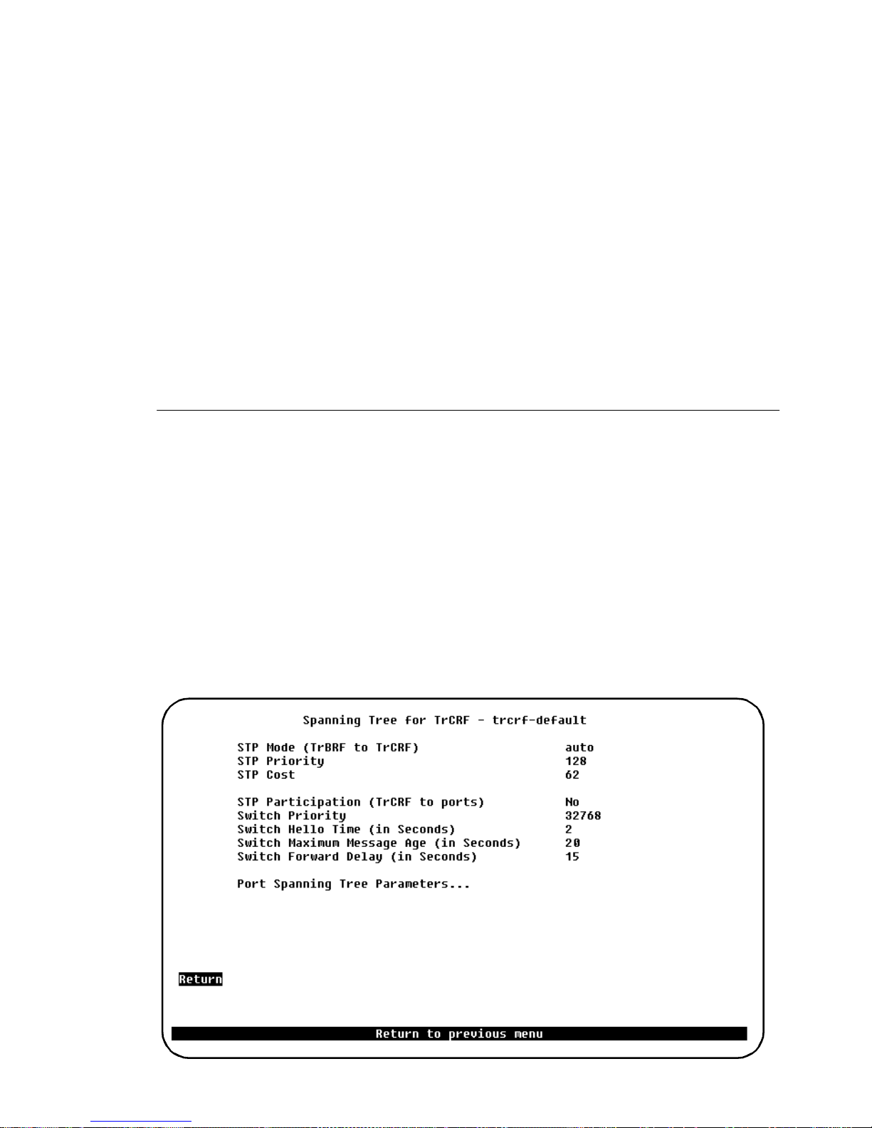
67
Bridge Forward Delay (in Seconds)
Enter t he time the switch waits between transitions from listeni ng to learning, and
from lear ning to forwarding. The mini mum may not be less than the larger of 4 or
((
Switch Maximum Message Age
/ 2) +1). The maximum may not be highe r th an
30. The lower range limit that appears reflects the value currently selected for
Switch Maximum Age
.
Default:
15
TrCRF & Port Spanning Tree Parameters...
If you select the
TrCRF & Port Spanning Tree Parameters
item, you will be
presented with a screen listing the TrCRFs that have the current TrBRF as parent.
From this screen, you c an select a TrCRF and modify the TrCRF and/or port
parameters as desired.
Spanning Tree for TrCRF Screen
To open this screen from the main menu, do the fol lowing:
1. Select
Configuration
Spanning Tree.
→
VLANs appears.
2. Choose a T rBRF to ope n the
the
TrCRF & Port Spanning Tree Pa ramet ers.. .
Spanning Tre e fo r T r BRF
3. A screenwill app ear displayi n g the TrCRFs t hat have the cu rrently sel ected
TrBRF as parent. When you select a TrCRF from this list, the
for Tr CRF screen
is displayed.
A list containing availabl e TrBRF
screen and then select
item .
Spanning Tree
CrossFire 8 730 Switch R ef erence Guide, DOC-7047 v. 1.1 Switch Configuratio n
Page 82

68
STP Mode (Tr BRF to TrCRF)
Deter mines the mode of the internal port fr o m this TrCRF to its Tr BRF. Possible
values are
spanning tree protocol , then
by the pa rent T rBRF . If the T rBRF is not parti cipating in the s panning tree protocol,
then forwarding is the
STP Priority
Priority associated with the TrCRF . The TrCRF with the lowest priority value has
the highest priority and will forward the spanning tree frames. The default is
The possible range is 0 through
STP Cost
Cost asso ciated with the TrCRF. The spanning tree protoc ol uses path costs to
determine whi ch CRF to select as a forwar ding CRF. The r efore, lo wer numbers
should be as signed to C RFs that use f ast er medi a (such as FDX or Cro ssLink) , and
higher num bers should be assigned to CRFs that use slower media. The possible
range is 1 to
speed in Mbps.
auto, forwarding, blo ck ed
auto
.
65,535
default
. The default is 62. The recommended path cost is 1000 /LAN
. If the par ent TrBR F is p ar ticip a ting in the
is t he de faul t, and the protocol wi ll be determin ed
128
(decimal).
255
.
STP Participation (T rCRF to ports)
Wheth er this TrCRF participates in the s panning tree proto col and, if so, the
protocol to be use d. Possible values are No,
The recommended proto col is IEEE, but if the TrCRF conta ins more th an one port
and the port(s) are connecte d to SRT bridges running the IEEE Spanning Tree
Protocol (using the IEEE group address), the n the Cisco protocol should be used.
•
If
STP Participation
set to forwarding mode. You can then ov erride this by blocking a particular port.
•
If
STP Partic i pa tio n
be used to determine the
configured with an STP mode of
Switch Priority
Prior ity value for this switch (0 through
higher the priority. The bridge or switch with the lowest priority value in a spanning
tree beco mes the root. The defaul t is
select
Port Spanning Tree Parameters...
is set to No, then all ports belonging to this TrCRF will be
is set to
forwarding/blocked
IEEE
auto
32,768.
or
Cisco
.
65,535
(To c hange i ndividua l port pr oper tie s,
).
and
IEEE
). The lower the priority value, the
Cisco
, then the selected protocol will
mode of the ports that are
. The de f au lt is No.
Switch He llo Ti m e (i n S econds)
Time the switch waits before sending the next configuration message when this
CRF is the root in STP. The default is 2.
CrossFire 8730 Switch Reference Guide, DOC-7047 v. 1.1 Switch Configuration
Page 83

69
The minimum value is 1. The maximum value is the lower of 10 or ((
Maximum Message Age
The valid range for this parameter is displayed when you select
/ 2) – 1).
Switch Hello Time
Switch
Switch Maximum Message Age (in Seconds)
Maximum m essag e age us ed when t his CRF is th e root in S TP. T his p ara mete r se ts
the time at which the configur ation message use d by the spanning tree algorithm
should be dis carded. The defaul t is 20. The minimum value is the higher of 6 or
((
Switch Hello Time
The maximu m cannot be m ore than the lower of 40 or ((
x 2) + 1).
Switch Forward Delay
x
2) – 1).
The range l imits tha t appear when you sele ct this parameter a re calcula ted usin g the
values currently selected for
Switch Hello Time
and
Switch Forward Delay
.
Switch Forward Delay (in Seconds)
The time the swi tch waits between transitions from listening to learning and from
learning to forwarding. The defa ult is 15. The minimum is the larger of 4 or
((
Switch Maximum Message Age /
2) + 1). The maximum is 30.
.
The lowe r range limit t hat appears when you s elect this pa rameter reflec ts the v alue
currently selected for
Switch Maximum Age
.
Port Spanning Tree Parameters...
Selecting this item brings up the
Port Spanning Tree Parameters
screen.
CrossFire 8 730 Switch R ef erence Guide, DOC-7047 v. 1.1 Switch Configuratio n
Page 84
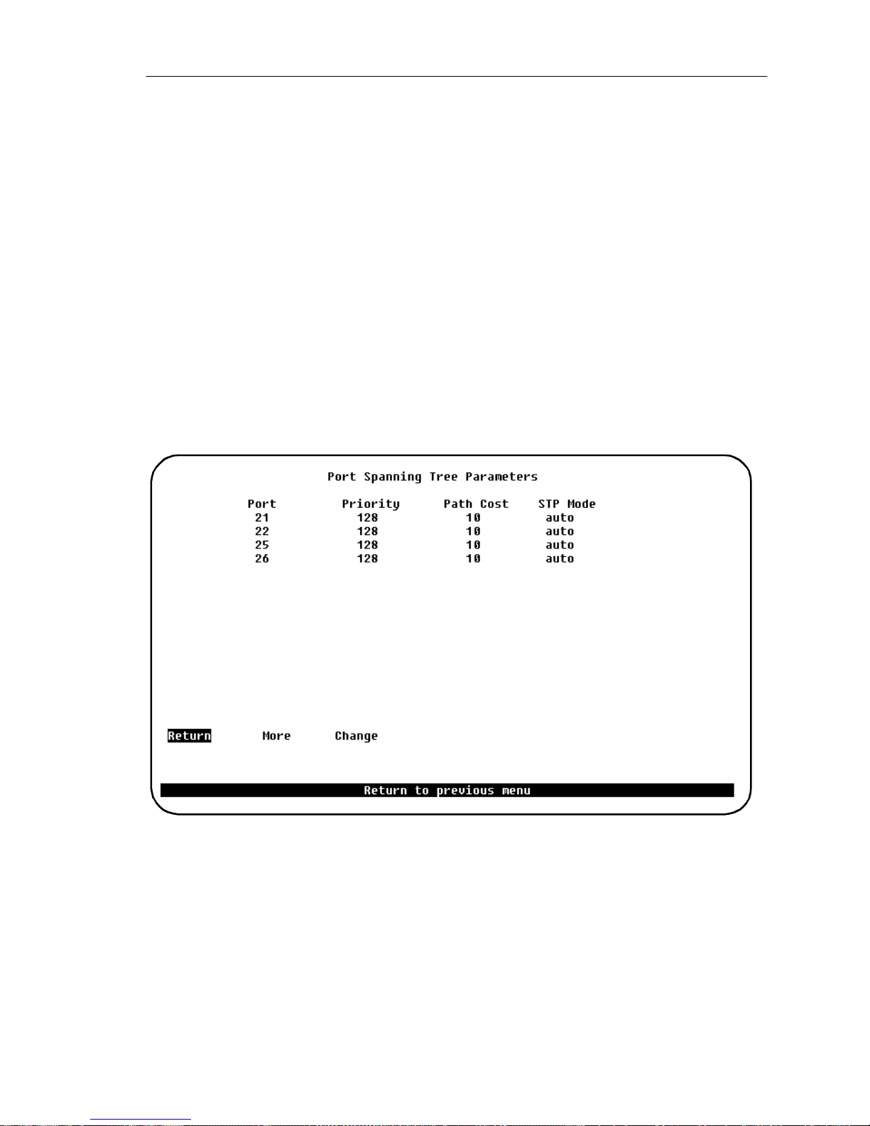
70
Port Spanning Tree Parameters Screen
To open this screen do the following:
1. Starting from the mai n me nu, s elect
Configuration
Spanning Tree.
→
A list
containi ng available TrBRF VLANs appears.
2. Choose a TrBRF to o pen t he
the
Tr CRF & Port Spanning Tree Parameters...
Spanning T ree f or TrBRF
screen and then select
item.
3. A screen will appear displaying the TrCRFs that have the currently selected
TrBRF as parent. When you sele ct a TrCRF from this list, the
for Tr C R F screen
4. On the
Spanning Tree for TrCRF
is displayed.
screen, select
Port Spanning Tr ee
Spanning Tree
Parameters...
Use the
Port Spanning Tree Parameters
screen to set up STP priorities for each port.
Port
The number of the port.
Priority
Prior ity associated with the port . The port with the lowest priority value has the
highest priority and will forward the spanning tree frames. The default is
possible range is 0 through
the lowe st port number forwards the spanning tree frames.
CrossFire 8730 Switch Reference Guide, DOC-7047 v. 1.1 Switch Configuration
128
(decimal). If all ports hav e the same priorit y va lue,
255
. The
Page 85

71
Path Cost
Cost associated with the port. The spanning tree protocol uses port path costs to
determine which port to select as a forwar ding port. Therefore, lower num bers
should be assigned to ports atta ched to faster media (such as FDX or CrossLink),
and higher numbers should be assigned to ports attached to slo w er media. The
possible range is 1 to
65, 5 35
. The default is 62. The recommended pa th cost is
1000 / LAN speed in Mbps.
STP Mode
The port ’s spanning tree mode. P ossible values are
forwarding, blocked
, and
auto
If the T rCRF to which the port be longs is partici pating in the spanning tree prot ocol,
then
is the defaul t and t he select ed prot ocol will be use d to det ermin e whethe r
auto
the port is forwardin g or blocked. If the TrCRF to whic h the port belongs is not
partic ipating in the spanning tree protocol, then
forwarding
is the default.
More
To view more ports in the table.
Change
To change or add values to specific ports.
Current Spanning Tree Information Screen
A summary of STP information for each port is available from the
Spanning Tree Information
screen. See page 173 in Chapter 4, “Monitoring the
Network from the Statistics Menu” for more information.
Curren t
.
CrossFire 8 730 Switch R ef erence Guide, DOC-7047 v. 1.1 Switch Configuratio n
Page 86
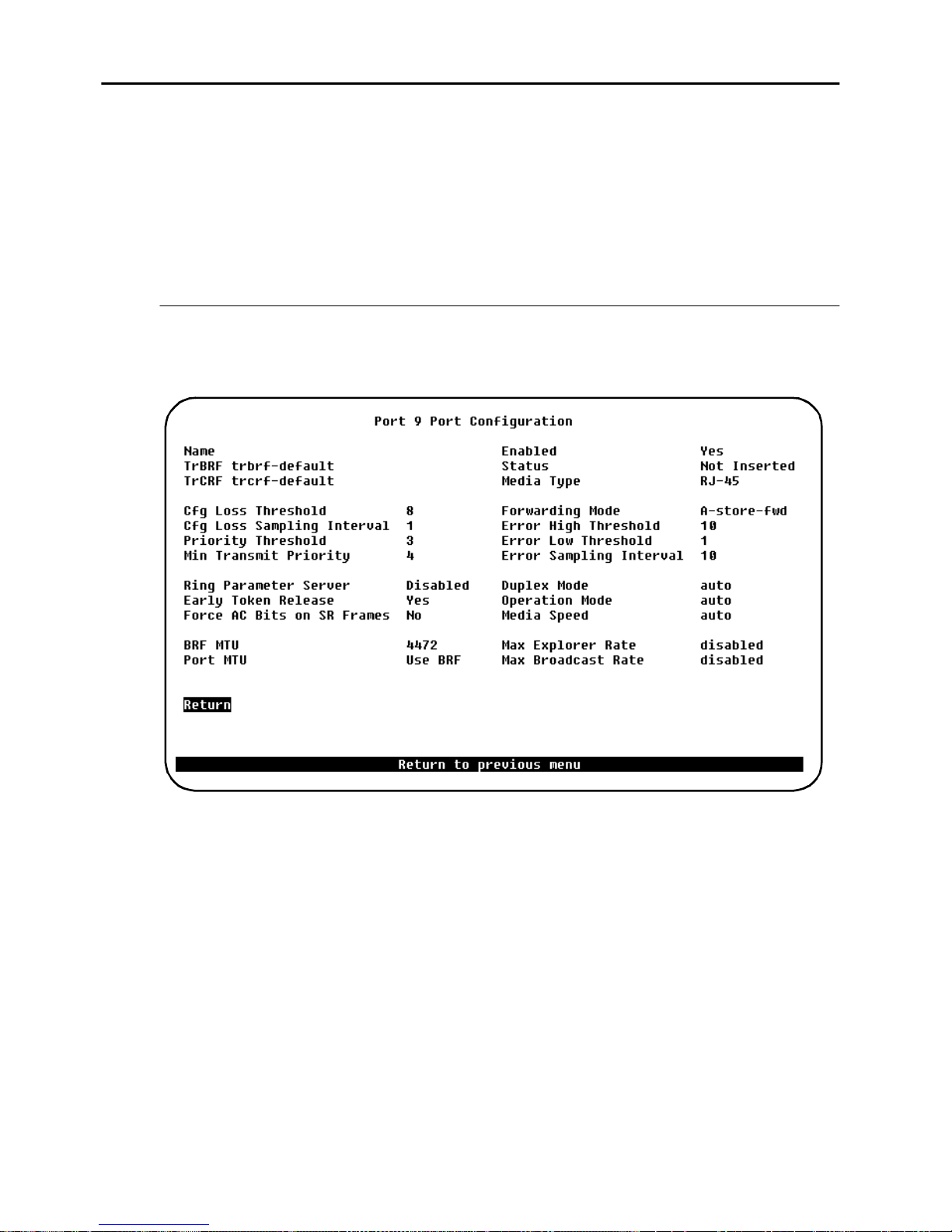
72
Port Configuration Screen
To open this screen do the following:
1. Start ing from the main me nu, select
2. You will be prompted for a port number. Token-Ring ports are 1-20, Fast
Ethernet port s are 21, 22, 25, or 26. When you ha ve ent ered the port number , the
Port Configuration
screen for that port will be displayed.
Configuration
Port Configuration.
→
Token-Ring Port Configuration
The Token-Ring ports are between 1 and 20. For these ports you will see the
following screen:
➽ Note:
operational fiel d value shown will be prefixed with A-.
Name
This field is for as signing a name to the Toke n-Ring port.
TrBRF
This field is for informational purposes only, and shows the parent TrBRF of the
TrCRF tha t the port is assigned to.
TrCRF
This field is fo r informational purposes only, and shows the TrCRF that the port is
assigned to.
CrossFire 8730 Switch Reference Guide, DOC-7047 v. 1.1 Switch Configuration
When
is selected for fie ld s th a t s u pp o r t th e a ut o op t io n , th e curren t
auto
Page 87

73
Enabled
For the Token-Ring ports 1-20 this variable shows if the port is currently enabled
via manag ing. Poss ible valu es are
is
Yes
.
(enabled) or No (disab led). The de fault v alue
Yes
Status
This field is for informat ional purposes only, and shows if the port is curr ent ly
inserted into the ring.
Address Demand Aging Level
Sets the threshold on the number of ent ries in the addre ss table on which entri es are
aged fa st er . Pos si b le values are 50, 60, 70, 80 and 90 percent and
Disable d
.
Default:
90 percent
.
Trace Mask
Sets a bit mask for which messages are logged in the message log. This is mainly
for debugging purposes by Olicom support.
Media Ty pe
This fie ld is for inform atio nal purpo ses onl y, and sh ows the m edia t ype of t he port .
The v alue will always be
RJ-45
, since this is the type of all the ports on CrossFire
8730.
Me d ia Speed
The Token-Ring media speed. Pos sibilities are 4 or
swi tch por t co nfigured with
discovers a connection to shared me d ia, it will
Auto
16 Mbps
or
Auto
. When a
open and insert into the ring. If the open returns with an indicatio n, that the port is
the first s tation to enter the ring, it will close.
Thi s algorithm is an alogue to that of auto-sensing adapters, which dictates that an
adapte r, which is capable of speed adjust ment, must have some other statio n on the
ring (typically a serv er), from which it can sense the network speed.
If you want to have switch ports, which are attached to shared media, it is
recommended t hat you cha nge the de fault m edia spe ed config uration from
either 16 or
4 Mbps
Max Exp lo r er R a te on Inpu t
The maximum Explor er frame forwarding rate per second. Possible values are
Disabled
(def au lt) or 0 -
MTU
The
Maximu m Transfe r Unit
sent or received. Poss ible valu es are
CrossFire 8 730 Switch R ef erence Guide, DOC-7047 v. 1.1 Switch Configuratio n
to
Auto
.
.
5000
is the size of th e information field of packets to be
1,500
and
4,472
(default),
8,144
, and
17,800
.
Page 88

74
The actual value used depends also on the value configured for the TrBRF (the
smaller value is used).
These values correspond to maximum frame size values of
9,236
➽ Note:
Translation Switch Installation Guide
Force AC Bits on SR Frames
This field specifies if AC bits will be set unconditionally when a port forwards
certain LLC frames. Possible values are
Early Token Release
Whether the port is enabled for Early Token Release (ETR). Possible values are
and No. The default is
is 4 Mbps, the switch will force
Operation Mode
The Token-Ring port operation mode. Possible values are as follows:
•
1,548, 4,546
, and
18,192
See the description on frame length limit in the
(default. Only HDX and FDX modes can be automatically detected.)
Auto
respectively.
. If
Yes
Early Token Release
CrossFire 8730 Fast Ethernet
.
and No (default).
Yes
is set to
Early Token Release
to
and the media speed
Yes
No.
(default),
Yes
•
HDX port
•
HDX station
•
FDX port
•
FDX station
•
RI/RO
Only on ports 19 and 20.
•
Passive
(this value is not user-selectable, and will be displayed if the port has been
selected as a passive monitoring port on the
Forwarding Mode
Forwarding mode that will be used to transmit frames. Possible values are
through
, the actual mode will depend on the number of errors that occur during the
auto
sampling interval. If the error rate is below the error low threshold, then
mode is used. If the error rate is above the error high threshold, then
is used. The
media speed of 4 Mbps and for teh Fast Ethernet ports.
, and
store & forward
store & forward
Switched Port Analyzer
. The default is
mode is always used for Token-Ring ports with a
. If the forwarding mode is set to
auto
cut-through
store & forward
screen).
auto, cut-
CrossFire 8730 Switch Reference Guide, DOC-7047 v. 1.1 Switch Configuration
Page 89

75
Priority Th res h ol d
The highest Toke n-Ring frame priority that will go to the low priority tra nsmit
queue. Possible values are 0–7. The default value is 3).
Min Transmit Priority
The minimum Token-Ring frame priority that will be used for transmits. Possible
values are 0–6. The defaul t value is 4.
Error High Threshold
This fiel d is only valid when
a port to
store & forward
Forwarding Mode
mode when the percentage of errors detected in the
Sampling Interval is more than the error high threshold. Possible values are 0–
percent. The de fault value is
percent.
10
is set to
, and is used to forc e
auto
100
Error Low Threshold
This field is onl y valid when
a port to
cut-through
mode when the perce ntage of errors detecte d in the Sampl ing
Forwarding Mode
Inte rval i s le ss tha n t he err o r l ow t hr esh o ld. Pos sib l e v al ues are 0–
is set to
, and is used to return
auto
percent. The
100
defa u l t value is 1 percent.
Error Sampling Interval
This field is only valid when
Forwarding Mode
is set to
, and specifies a
auto
samplin g period in minutes. Th e s am pling period is used when counting errors to
determine a ports for warding mo de. Possi ble values are 1–
minutes. The default
60
value is 10.
Cfg Loss Thre s ho ld
Configuration loss occurs when a port completes a conne ction, allows data traffic
to flow, and subs equently closes. This threshold is used to control the number of
configura tion lo sse s that c an occu r with in the
Cfg L os s Sa m pl i ng Inter v a l
. When
the threshold is exceeded, the port is disabled and must be enabled via this screen
or an SNMP manager. Possible values are 1–
The default value is 8.
100.
Cfg Loss Sampling Interval
Specifies a sampling period in minutes. The number of configuration losses occurring
within this interval is compare to the
should be disabled. Possible values are 1–60 minutes. The default value is 10.
➽ Note:
If you change any co nfigurat ion parameter s of a connected port, the port will
close and reo pen and you will lose all address info rmation and stati st ics for that
port.
CrossFire 8 730 Switch R ef erence Guide, DOC-7047 v. 1.1 Switch Configuratio n
Cfg Loss Threshold
to d etermine if a port
Page 90
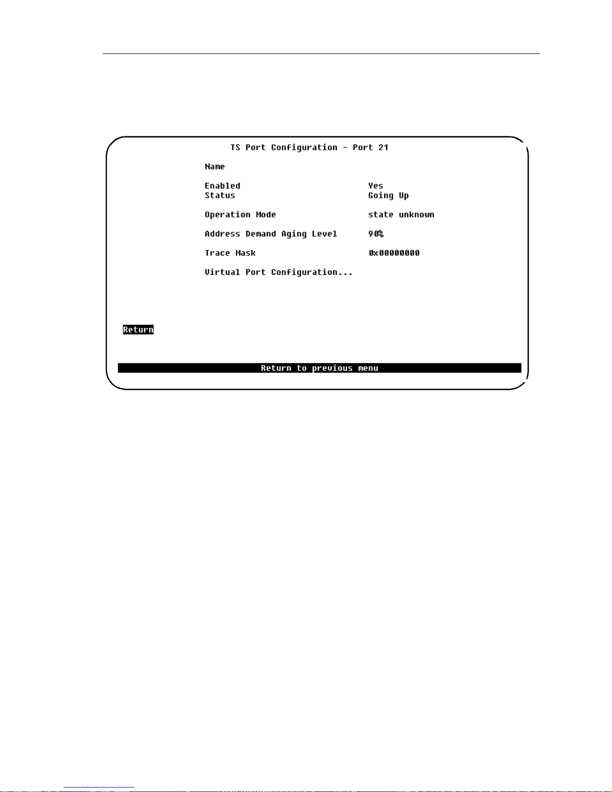
76
Fast Ethernet Port Configuration
The Fast Ethernet ports are 21, 22, 25, and 26. For these ports you will see the
following screen,
TS Port Configuration
:
Name
This field is for as signing a name to the port.
Enabled
For the Fast Ethernet ports 21, 22, 25, and 26, th is variable se ts the administrative
state of the port, possible values are
LINK LED will blink.
Default:
Status
This field is for informational purposes only, and shows if the port is currently
inserted into the ring. The value displayed ca n be one of th e following:
•
Down
•
Going Up
•
Up
Yes
.
The port is down.
The port is enabled and the auto-negotiation is trying to
establish a protocol connection.
The port is up.
and No. When the port is disa bled, the
Yes
CrossFire 8730 Switch Reference Guide, DOC-7047 v. 1.1 Switch Configuration
Page 91

77
Operatio n Mode
This paramet er displays the mode of the Fast Ethernet por t. The value can be one
of the foll o w in g:
•
Auto FDX 10
•
Auto FDX 100
•
Auto HDX 10
•
Auto HDX 100
•
state-unknown
Address Demand Aging Level
Sets the threshold on the number of ent ries in the addre ss table on which entri es are
aged fa st er . Pos si b le values are 50, 60, 70, 80 and 90 percent and
Default:
Trace Mask
Sets a bit mask for which messages are logged in the message log. This is mainly
for debugging purposes by Olicom support.
Virtual Port Configuration
90 percent
The port is running in full duplex 10Mbps
The port is running in full duplex 100Mbps
The port is running in half duplex 10Mbps
The port is running in half duplex 100Mbps
The port is disabled or the link is off
.
Disable d
.
Opens the
Virtual Port Configuration
screen, see page 78.
CrossFire 8 730 Switch R ef erence Guide, DOC-7047 v. 1.1 Switch Configuratio n
Page 92
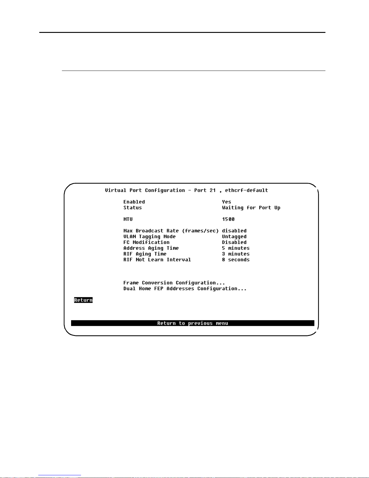
78
Virtual Port Configuration
This section describes virtual port configuration for the Fas t Ethernet ports.
Virtual Port Configuration Screen
To open this screen do the following:
1. Start ing from the main me nu, select
2. You will be prompted for a port numbe r. Select a Fast Ethernet port, that is, 21,
22, 25, or 26. If the Fast Ethernet port has more than one virtual port, a list of
the corre s ponding CRFs appears, from which the virtual po rt must be selected.
The
Port Configuration
3. On the
Port Configuration
scre en appears.
screen, select
Configuration
Virtual Port Configuration
Port Configuration.
→
...
The following menu options are available:
Enabled
Sets the administrative state of the virtual port, possible values are
Default:
Status
Display only. Shows the current status of the virtual port.
•
Admin down
CrossFire 8730 Switch Reference Guide, DOC-7047 v. 1.1 Switch Configuration
Yes
.
The port or virtual port is disabled.
Yes
and
No.
Page 93

79
•
Waiting for
port up
•
Up
•
Forwarding
•
Temporary down
MTU
You can only use the value
MTU configured:
Actual Fast Ethernet frame size:
LF bits:
Max Broadcast Rate (frames/sec)
Sets the maximum broadcast frame rate; possible values are 0 to
or
Disabled
forwarded from the Fast Ethernet side of the virtual port to the switch.
. If enabled, this will limit the amo unt of broadcast frames being
The virtual port is waiting for the port to come up.
The virtual port is up but not forwarding.
The virtual port is up and forwarding.
The virtual port is currently do wn because the port is
temporarily down.
as MTU.
1500
1500
1558
001
5000
frames/sec
Default:
VLAN Tagging Mode
Sets the VLAN tagging mode of the virtual port; possible values are
Untagged
port ca n be unt ag ged. Al l o ther vi rtu al port s mu st be t agged a nd the 802 .1Q VLAN
ID must be the same in both ends.
Prefer ably, the VLAN which is expected to have the largest amount of traffic
should be untagged, since VLAN tagging does impose a small overhead.
Default:
FC Modi fication
Enabled F C modification preserves frame priority during translation between
Ethernet a nd Token-Ring (both directions). Possible values are Enable d and
Disabled. As discussed earlier a VLAN frame tag also cont ains a 3-bit priority field.
If FC modification is enabled, the Token-Ring frame priority in the FC byte is set
to th e f rame tag pr iority. If FC modification is disabled, the FC priority is set to 0,
and the frame tag priority is discarded.
Disabled
Tagged
. As explaine d previously at most one virtual port on each Fast Ethernet
Untagged
for the first virtual port and
Tagged
for the subsequent ports.
and
When a Fast Ethernet port ins erts a frame tag in a frame, and FC modification is
enabled the Fast Ethernet port uses the FC priority from Toke n-Ring frame.
Otherwis e the frame tag priority is set to 0 and the FC priority is discarded.
Default:
CrossFire 8 730 Switch R ef erence Guide, DOC-7047 v. 1.1 Switch Configuratio n
Disabled
Page 94

80
Address Aging Time
Sets the aging time for address es learned on an Fast Ethernet port. Possible value
are 1 to
minutes or 0 to
9999
disable aging
. When there has been no activity on an
address using the RIF entry for the spe cified period of time it is deleted from the
RIF tables.
➽
Default: 5
minutes
RIF Aging Time
Sets the aging tim e for RIF entrie s lear ned on a Fast Ethernet port. Poss ible va lues
are 1 to
minutes or 0 to
9999
disabl e aging
. When no frames with the RIF have been
receive d for the sp ecified pe riod of time the RIF entry is deleted from the RIF table
and the status is changed to
RIF unknown
.
This is also tr u e for add r ess es le arn t f rom trans pa re nt fra me s. Su ch ad dres se s ha ve
the
no RIF
Default: 3
status set. In such case the status is aged to “RIF unknown” status.
minutes
RIF Not Learn Interval
Sets the learning blocked interval for RIF entries. Possible value are 0 to 900
seconds. A new RIF c ann ot be le arned unl ess a s peci fied pe riod of ti me has passe d
since the current RIF entry was learned.
Default:
8 seconds
CrossFire 8730 Switch Reference Guide, DOC-7047 v. 1.1 Switch Configuration
Page 95
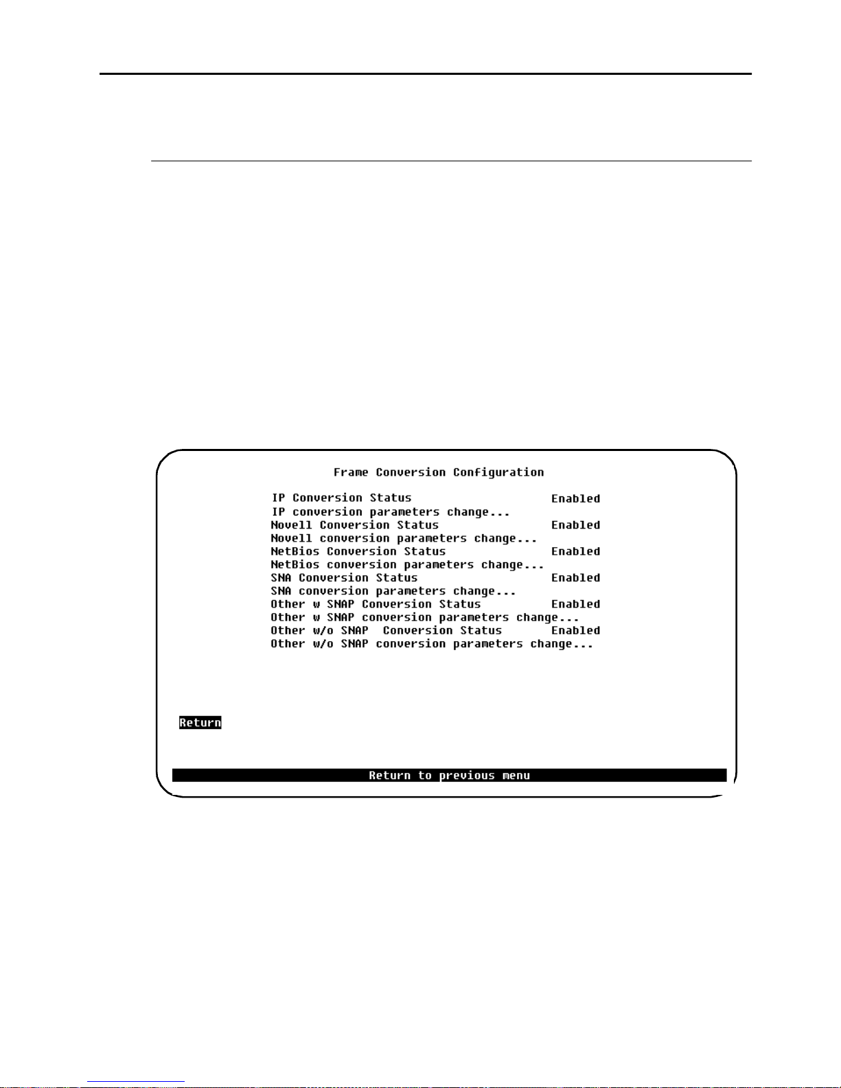
Frame Conversion Configuration
This section describes how to configure fram e con vers ion on a Fast Ether net port.
Frame Conversion Configuration Screen
To open this screen do the following :
81
1. Starting from the main me nu, select
2. You will be prompted for a port number. Token-Ring ports are 1-20, Fast
Ethernet p orts are 2 1, 22, 25, or 26. When you ha ve e ntered the port number , th e
Port Configuration
3. On the
4. On the
Configuration...
Port Configuration
Virtual Po rt Configuration
screen for that port will be displayed.
screen, select
. The
Frame Conversion Configuration
Configuration
Virtual Port Configuration
screen, select
Port Configuration.
→
Frame Conversion
screen appears.
...
IP Conversion Status
Information only. Shows the current status of the IP Conversion.
Possi bl e v al u es ar e
CrossFire 8 730 Switch R ef erence Guide, DOC-7047 v. 1.1 Switch Configuratio n
Enabled
and
Disabled
.
Page 96

82
IP Conversion Parameters Change...
This item opens a s creen on which you can change IP conversion parameters. See
page 83 for information.
Novell Conversion Status
Information only. Shows the current stat us of the Novell Conver si on.
Possible values are
Enabled
and
Disabled
.
Novell Conversion Parameters Change
This item opens a screen on which you can change Novell conversion parameters.
See pa ge 85.
NetBios Conversion Status
Information only. Shows the current stat us of the NetBios Conversion.
Possible values are
Enabled
and
Disabled
.
NetBios Conversion Parameters Change
This item open s a screen on which you can change Net Bios convers ion paramete rs.
See pa ge 87.
SNA Conversion Status
Display only. Shows the current status of the SNA Conversion.
Possible values are
Enabled
and
Disabled
.
SNA Conversion Parameters Change
This item opens a screen on which you can change SNA conversion parame ters.
See pa ge 89.
Other Frames w/SNAP Conversion Status
Display only. Shows the current status of the Other Fram es With SNAP
Conversion. Possible values are
Enabled
and
Disable d
.
Other Frames w/SNAP Conversion Parameters Change
This item opens a screen on which you can change
Conversion
parameters.
Other Frames w/SNAP
Other Frames w/o SNAP Conversion Status
Display only. Shows the current status of the Other Fram es Without SNAP
Conversion. Possible values are
Other Frames w/o SNAP Conversion Parameters Change
This item open a scre en on which you can change
Conversion
CrossFire 8730 Switch Reference Guide, DOC-7047 v. 1.1 Switch Configuration
parameters.
Enabled
and
Disable d
.
Other Frames w/o SNAP
Page 97
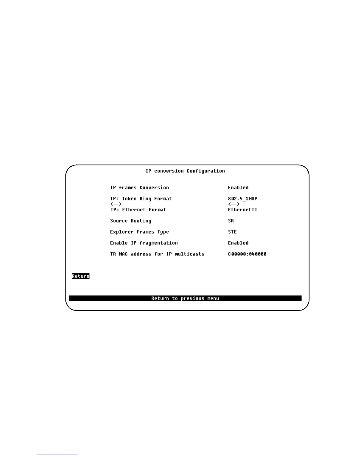
IP Frames Conversion Screen
To open this screen do the following :
83
1. Starting from the main me nu, select
2. You will be prompted for a port number. Token-Ring ports are 1-20, Fast
Ethernet p orts are 2 1, 22, 25, or 26. When you ha ve e ntered the port number , th e
Port Configuration
3. On the
4. On the
Configuration...
Select
Port Configuration
Virtual Po rt Configuration
IP Conversio n Pa ra m et e rs C h a ng e
screen for that port will be displayed.
screen, select
The
Frame Conversion Configuration
Configuration
Virtual Port Configuration
screen, select
...
Port Configuration.
→
Frame Conversion
screen ap pe ar s.
...
IP Frames Conversion
Sets the state of the IP frames Conversion. Possible values are
Disabled
Default:
IP: Token-Ring Format
Sets the format of IP fr ames on Toke n-Ring. Available formats:
•
CrossFire 8 730 Switch R ef erence Guide, DOC-7047 v. 1.1 Switch Configuratio n
. If the state is set to
Enabled
802.5 SNA P
.
Enabled
Disabled,
Frame in the IEEE 802.5 format with SNAP
IP traffic will be dropped.
and
Page 98

84
IP: Ethernet Format
Sets the format of IP fram es on Ethernet. Availa ble formats:
•
802.3 SNAP
•
Etherne t II
Default:
Source Routing
Enables or disables Source Routing in IP frames transmitted to Token-Ring. The
possible values:
•
•
Default: SR.
Explorer Frames Type
Sets the types of explorer that should be used for IP traffic. Possible values:
ARE
Etherne t II
SR
noSR
Frame in the IEEE 802.3 format with SNAP
Frame in Ethernet II format
.
Source Routing information will be added to frames
converted from Ethernet to Token-Ring format.
Frame will be transmitted to Token-Ring as a transparent
frame.
The All Routes Exp lorer should be used.
STE
Default:
Enable IP Fragmentation
Enables or disa bles fragmentation of IP f rames rec eived from Token-Ring and
transmitted to Ethernet. The possible values are
Default:
TR MAC Address for IP Multicasts
Allo w s en t e r i ng th e I P m u lt icast ad dress. The a d dr e s s is en t e r e d in th e MAC
address format.
Default:
(change to ARE for typical Token-Ring behaviour for ARP frames)
STE.
Enabled
C00000:040000
The Spanning Tree Explorer should be used.
Enabled
.
.
and
Disabled
.
CrossFire 8730 Switch Reference Guide, DOC-7047 v. 1.1 Switch Configuration
Page 99
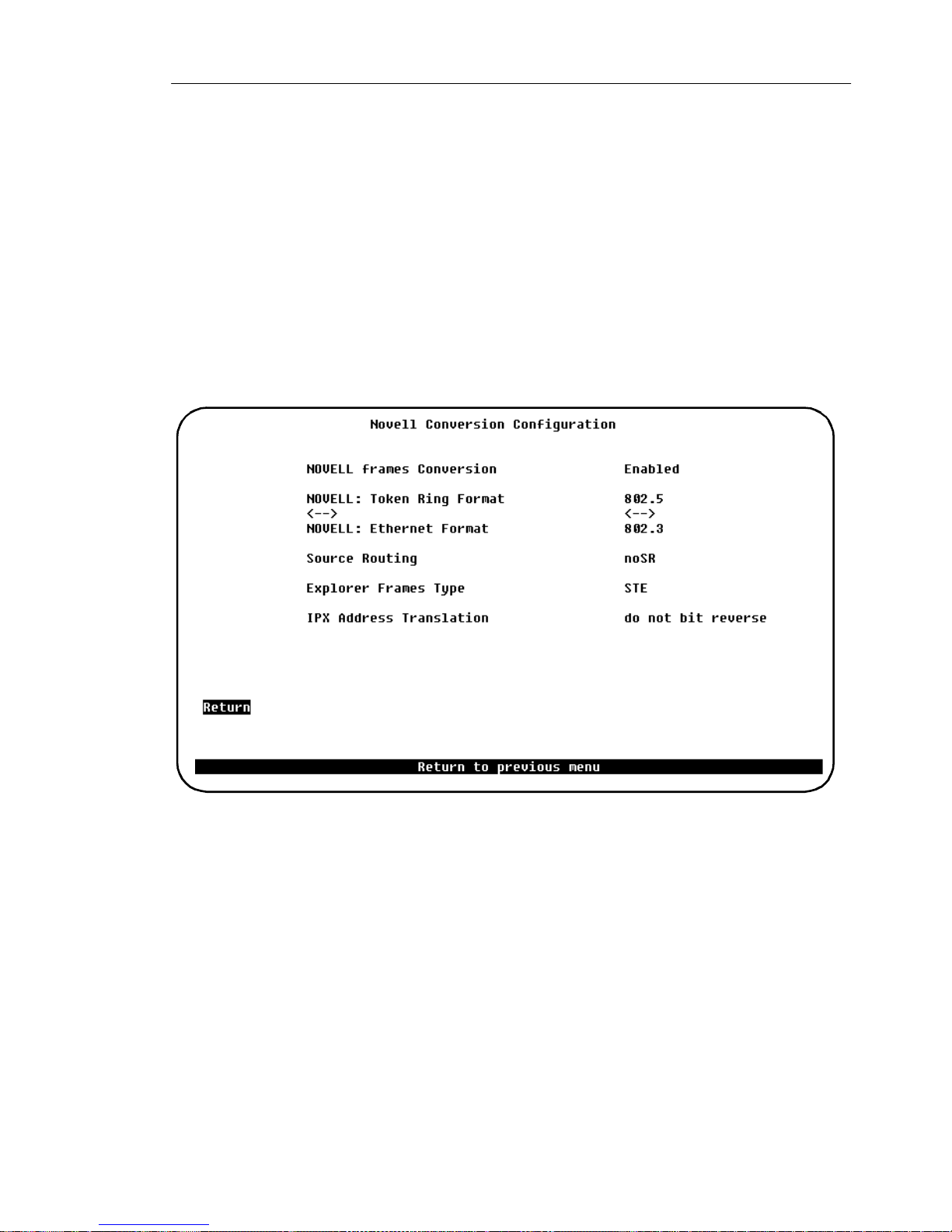
Novell Conversion Configuration Screen
To open this screen do the following :
85
1. Starting from the main me nu, select
2. You will be prompted for a port number. Token-Ring ports are 1-20, Fast
Ethernet p orts are 2 1, 22, 25, or 26. When you ha ve e ntered the port number , th e
Port Configuration
3. On the
4. On the
Configuration...
Select
Port Configuration
Virtual Po rt Configuration
Novell Conversion Parameters Change
screen for that port will be displayed.
screen, select
. The
Frame Conversion Configuration
Configuration
Virtual Port Configuration
screen, select
...
Port Configuration.
→
Frame Conversion
screen appears.
...
NOVELL Frames Conversion
Determines how Novell frames are converted. Possible values ar e
Disabled
Default:
NOVELL: Token-Ri ng Form a t
Sets the format of Novell frames on Token-Ring. Available formats :
•
•
Default:
CrossFire 8 730 Switch R ef erence Guide, DOC-7047 v. 1.1 Switch Configuratio n
. If the state is set to
Enabled
802.5 SNA P
802.5
802.5
Enabled
Disabled
Frame in the IEEE 802.5 format with SNAP
Novell naming convention: Token-Ring SNAP
Frame in the IEEE 802.5 format without SNAP
Novell naming convention: Token-Ring
Novell traffic will be dropped.
and
Page 100

86
NOVELL: Ethernet Forma t
Sets the format of Novell frames on Ethernet. Ava ilable formats:
•
802.3
•
Novell 802.3
•
802.3 SNAP
•
Etherne t II
Default:
Source Routing
Enables or dis ables Source Routing in Novell frames transm itted to Token-Ring.
Possible val ues:
•
•
802.3
SR
noSR
Frame in the IEEE 802.2 format
Novell naming convention: 802.2
Frame in the IEEE 802.3 format
Novell naming convention: Normal 802.3
Frame in the IEEE 802.3 format with SNAP
Novell naming con vention: Ethernet SNAP
Frame in Ethernet II format
Novell naming con vention: Ethernet II
Source Routing information will be added to frames
converted from Ethernet to Token-Ring format.
Frame will be transmitted to Token-Ring as a transparent
frame.
Default:
Explorer Frames Type
Sets the type of explorer that should be used for IPX traffic.
Possible val ues:
•
•
Default:
IPX Address Translation
Enables and di sables rever sing MAC address bits in Novell f rames.
The possible values are
Default:
noSR
ARE
STE
STE
do not bit reverse
The All Routes Exp lorer should be used.
Spanning Tree Explorer sh ould be used.
do not bit reverse
and
bit reversed
.
CrossFire 8730 Switch Reference Guide, DOC-7047 v. 1.1 Switch Configuration
 Loading...