

Page 1

Model: A400A
ADSL Router
User's Guide
Version 1.19
(August 9, 2001)
Page 2

Contents
Important Safeguards................................................................ 1
Overview ................................................................................. 3
1. Packing list .........................................................................................3
2. Taking a look at the ADSL router........................................................4
2. 1 Front View....................................................................................4
2. 2 Rear View.................................................................................... 5
Installation ................................................................................. 6
1. Setting up the router...........................................................................6
2. Installation of the application program of RouterAP .......................... 8
Configuration.............................................................................. 9
1. Configuring the ADSL router ..............................................................9
2. Quick Setup..................................................................................... 12
3. Advanced Configuration.................................................................. 23
LAN ................................................................................................. 2 3
DHCP.............................................................................................. 24
IP Sharing ........................................................................................ 2 8
Routing Protocol (RIP) .................................................................... 3 3
ISP (Internet Service Provider) ....................................................... 3 6
Spanning Tree ................................................................................. 3 7
SNMP.............................................................................................. 38
ATM Interface & VCs ...................................................................... 4 1
4. Special Function .............................................................................. 4 2
Packet Filter .................................................................................... 42
5. Maintenance .................................................................................... 44
User Profile ..................................................................................... 4 4
Monitor ............................................................................................ 46
Show Setting ................................................................................... 4 7
F/W Upgrade................................................................................... 49
Ping................................................................................................. 49
Save configuration to file & Restore configuration from file ........... 5 0
Reset to Default .............................................................................. 5 0
Save................................................................................................ 50
Reboot System ............................................................................... 51
Information ...................................................................................... 51
T roubleshooting....................................................................... 52
Page 3

1
Important Safeguards
Read and understand all instructions.
follow all warnings and instructions marked on the product.
Environment
y In-house stationary use, desktop or wall-mounted; the maximum
ambient temperature may not exceed 40°C (104°F) external to the
housing;
y It must not be mounted in a location exposed to direct or excessive
solar and/or heat radiation;
y It must not be exposed to heat trap conditions and must not be
subjected to water or condensation;
y It must be installed in a Pollution Degree 2 environment.
Cleaning
Unplug this product from the wall outlet before cleaning. Do not use
liquid cleaners or aerosol cleaners. Use a damp cloth for cleaning.
Water and moisture
Do not use this product near water, for example, near a bathtub, wash
bowl, kitchen sink, laundry tub, in a wet basement or near a swimming
pool.
Power sources
This product should be operated only from the type of power source
indicated on the marking labels. If you are not sure of type of power
supply to your home, consult your product dealer or local power company.
The main socket outlet must be near the equipment and easily
accessible.
The router equipment is not intended to be connected to an IT-type
power system.
Power cord protection
Do not allow anything to rest on the power cord. Do not locate this
product where the cord will be subject to persons walking on it.
Page 4

2
Overloading
Do not overload wall (mains) outlets and extension cords as this can
result in the risk of fire or electric shock.
Servicing
To reduce the risk or electric shock, do not disassemble this product.
None of its parts are user-replaceable; therefore, no reason exists to
access the interior. Opening or removing cover may expose you to
dangerous voltages or other risks. Incorrect reassembly can cause
electric shock when the appliance is subsequently used.
If service or repair work is required, take it to qualified service personnel.
Damage requiring service
Unplug the computer from the wall outlet and refer servicing to qualified
service personnel under the following conditions:
y If liquid has been spilled into the product;
y If the product has been exposed to rain or water;
y If the product does not operate normally by following the operating
instructions;
y If the product has been dropped or damaged in any way;
y If the product exhibits a distinct change in performance.
Modem/Telephone use
Avoid using a modem/telephone (other than a cordless type) during an
electrical storm. There may be a remote risk of electric shock from
lightning.
Do not use the telephone to report a gas leak in the vicinity of the leak.
If telephone service is required on the same line and for optimum
ADSL performance or distributed filters must be installed. Depending
on your ADSL configuration and type of filters, installation must be
carried out by qualified service personnel. Consult your Telephone
Company of ADSL Service Provider for instructions.
SAVE THESE INSTRUCTIONS
Page 5

3
Overview
1. Packing list
Before set up the machine, inspect it visually for damage that might
have occurred during shipment. Make sure the box contains all of the
components listed below:
1. ADSL router
2. RJ-11 to RJ-11 phone cable
3. Adapter
4. DB-9 to RJ-14 Console cable (RS232)
5. RJ-45 to RJ-45 Ethernet cable
6. External Filter
7. CD-ROM (include: Configuration program of ADSLRouter, User
guide)
8. User guide
12 3
45 6
78
Page 6
4
2. Taking a look at the ADSL router
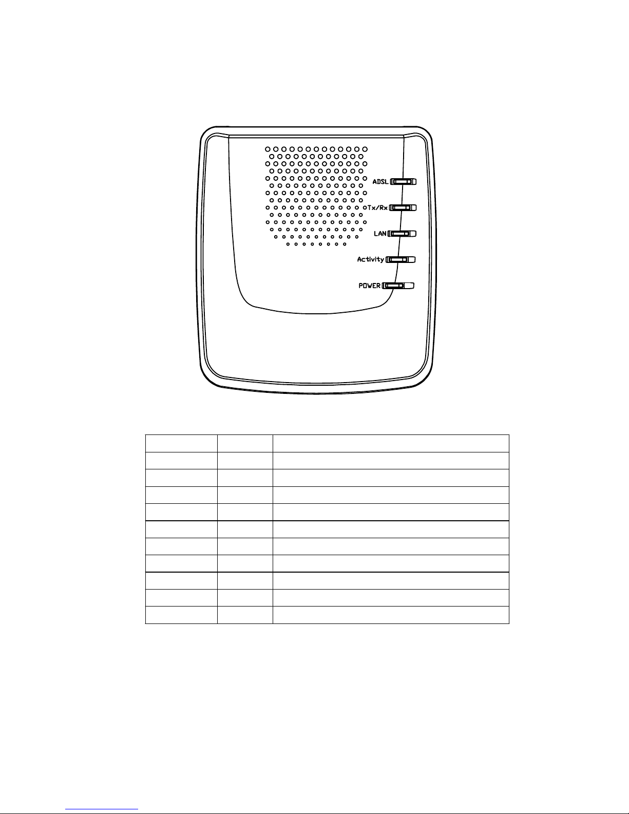
2.1 Front View
LED Name State Meaning
ADSL on ADSL line is ready for data transmission
flash ADSL line is ready for line connection
Tx/Rx flash Data is being trans m itted/received
off No transmit/receive activity
LAN On PC and the device is properly connected
Off PC and the device is not connected
Activity Flash Data is being transmitted/rece i ved
Off No transmit/receive activity
POWER On Power on
Off No power
Page 7
5
2.2 Rear View
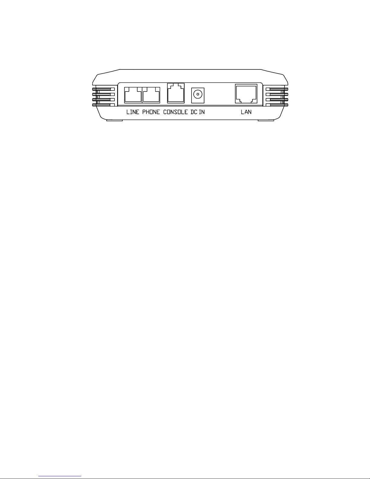
The LINE port lets you connect the device to one or more remote
networks over a ADSL connection.
The PHONE port lets you connect to the telephone line.
The CONSOLE port lets you connect the device to a personal
computer through the console cable to configure, administer and
monitor your ADSL router setting with Graphic User Interface (GUI).
The DC IN port lets you connect the device to an electrical power
supply.
The LAN port lets you connect network devices within a workgroup.
Page 8
6
Installation
1. Setting up the router
The location environment
Place the router in a location where air can circulate freely around it.
The router case has vents on top cover and its sides. Leave at least
two (2) inches of clearance between the vents on the both sides of the
router and any object that might restrict air flow. Never operate the
router when its vents are covered or obstructed.
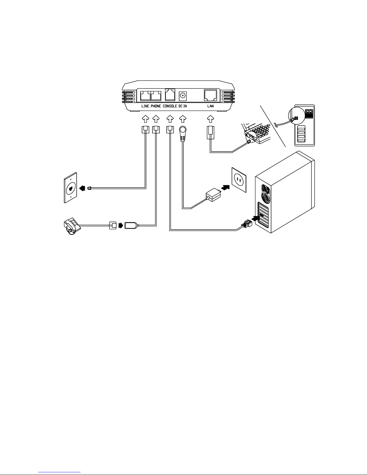
Connect your Wide Area Network
Plug one end of the phone cable in the port labeled LINE on the rear
panel of router until you feel it lock and connect the other end of line
to your ADSL wall jack.
Connect the CONSOLE port
The CONSOLE port lets you connect the router to a personal computer
through the console cable to configure, administer and monitor your
ADSL router setting with Graphic User Interface (GUI). (described in the
chapter of Configuration on page 10)
RJ-11 cable
Adapter
DB-9 to RJ-14 Console cable
RJ-45 Ethernet cable
External Filter
ADSL Service
Port on Wall
Page 9

7
a. Plug the RJ-14 end of console cable into the CONSOLE port on the
router back panel.
b. Connect the other DB-9 end of console cable to a serial port (COM1
or COM2) of your computer.
Connect the local devices
1. Insert one end of a ethernet cable into the ports labeled LAN port
on the rear panel of router until you hear click.
2. Connect the other end of the cable to the ethernet port on a personal
computer or other networked device.
3. If you require more than one hub port, you can connect the router
to another hub.
Connect the adapter
Plug the adapter connector into the socket labeled DC IN on the back
of the router and connect the other end into a properly wall outlet.
Note: 1. The power rating of the adapter is "Input: 220V 50Hz, Output:
9Vdc 1.1A".
2 . There is no power switch on this router. The power is on as long
as the router is plugged in.
Install a telephone filter
Converting your regular phone line into a high-speed Digital Subscriber
Line (DSL) can cause audible noise (high-pitched tones and static)
when you talk on the phone. You need to install a filter on each
telephone or device that shares the DSL Line to eliminate this noise.
Place on filter in every telephone jack that is directly connected to a
telephone, answering machine, fax or any other phone line device.
Unused jacks do not need a filter.
Page 10

8
2. Installation of the application program of Router AP
1. Start operation system.
2. Place the CD into your CD-ROM drive. Remember to allow the drive
fully getting the CD running before proceeding.
3. The Setup program will automatically install all of the required files into
the default c:\Program Files\ADSLRouter subdirectory. Follow all
onscreen instructions and then click "Finish" to complete the installation.
4. Or you may click "Start" and select "Run" from the pop-up menu. Type
"D:\Driver\Utility\Setup.exe" (Some user's CD-ROM driver could
designated to E, in this case, please select E:\Driver\Utility\Setup.exe).
Follow all onscreen instructions and then click "Finish" to complete the
installation.
Note: If your PC systems Windows OS is Win 95, you have to install the
program of WinSock 2.0 again after installation.
Page 11
9
Configuration
1. Configuring the ADSL router
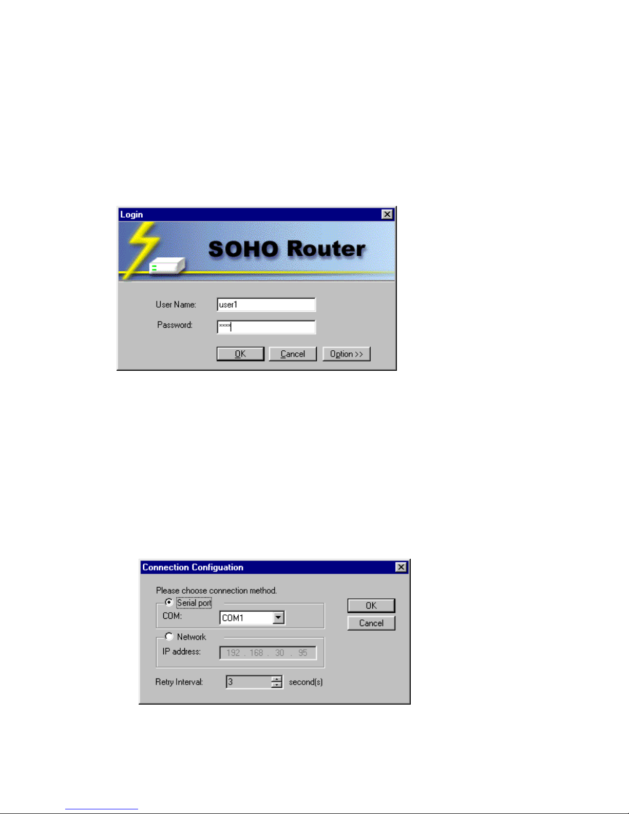
When you power up the router and launch the application program of
ADSLRouter and select "ADSL Router Configuration", the window will
display a Login screen and ask you to enter the user name and password,
as shown below:
1. User: Enter Your username lets the router record your access.
Give a username to validate its authorization. The default for user
is "user1".
2. Password: Enter the administrator password lets you display
and update all this router settings (The default is "root"). Enter
a user password lets you display but not update this router
settings (the default is test).
3. Click Option button to choose connection method.
Page 12

10
Options are : Serial port, Network
Serial port :You can use the attached console cable to connect the
router and a personal computer to configure, administer and monitor
your ADSL router with Graphic User Interface (GUI).
a)Plug the RJ-14 end of console cable into the CONSOLE port
on the router back panel.
b)Connect the other DB-9 end of console cable to a serial port
(COM1 or COM2) of your computer.
Network: Or you can open a Network connection from a
workstation on your network. You must know the IP address of
the router before you can make a Network connection to it. By
default , the router uses 192.168.1.1 as the IP address for its
LAN interface. You can use the Graphic User Interface (GUI)
to configure the router IP address.
Retry interval: Enter the timing of how many seconds you want
to reconnect the router if failure. (The default is 3 seconds.)
Page 13
11
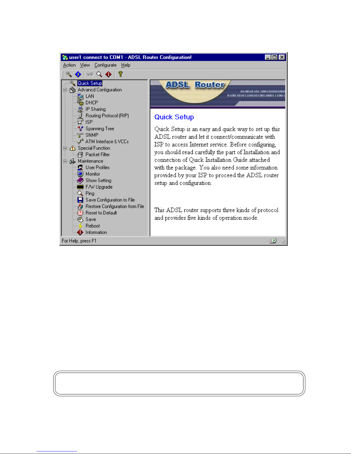
When you have logged in successfully, the Graphic User Interface (GUI)
will appear on the window to let you configuration the router.
The menu of Quick Setup opens the Quick Setup window, which lets you
enter basic settings for the router.
The menu of Advanced Configuration provides information on advanced
management features for network managers such as LAN, DHCP, IP
Sharing, Router Protocol etc.
The menu of Special Function includes Packet Filter.
The menu of Maintenance describes maintenance features for checking
system status and F/W upgrade etc.
Note: Double click each options of main page to enter each Graphic User
Interface (GUI) configuration window to enter parameter.
Page 14
12
2. Quick Setup
Gathering Configuration Information
Before you configure this ADSL router, you need to gather information
about your networks. Most users will only need to complete the Quick
Setup section.
For many users, the default configuration of the product will provide all
the necessary services. Some DSL service providers may require
settings that vary from the default configuration. In such cases, you
should contact the service provider or network administrator and have
them complete the Quick Setup.
Entering Basic Settings
The Quick Setup window lets you enter basic configuration information
for your ADSL router. If you have overridden the default settings for
IP address information and entered IP address information manually,
you can use the Quick Setup window to display and modify those
settings.
Quick Setup is an easy and quick way to set up this ADSL router and
let it connect/communicate with ISP to access Internet service. Before
configuring, you should read carefully the part of Installation and
configuration. You also need some information provided by your ISP
to proceed the ADSL router setup and configuration.
This ADSL router supports three kinds of protocol and provides five
kinds of operation mode.
To decide what kind of protocol, it depends on the structure and services
provided by your Internet Service Provider, please follow the instruction
of Quick Setup window to enter the parameter.
Note: Click the question mark
in the title bar of the dialog box to view
on-line description about each field of the Graphic User Interface.
Page 15
13
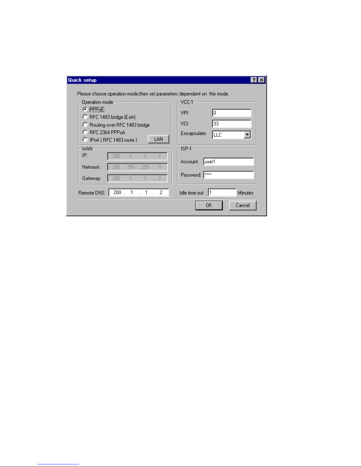
PPPoE
The Bridged protocol data unit is encapsulated using RFC 1483 protocol
over an ATM network and this operation supply PPPoE function to let
the router connect with ISP.
1. VPI: Enter the number of the virtual path identifier in the VPI
field.
The VPI is a number in the range 0-255. Consult your ATM transport
administrator for what number you should enter in this field.
2. VCI: Enter the number of the virtual circuit identifier in the VCI
field.
The VCI is a number in the range 0-65534. Consult your ATM
transport administrator for what number you should enter in this field.
3. Encapsulate: Select the encapsulation setting.
You choose LLC or VC Mux to configure whether the virtual circuit
uses LLC-SNAP encapsulation or Vc-based multiplexing.
4. Account: Enter the account provided by your ISP in the Account
field.
5. Password: Enter the password provided by your ISP in the
Password field.
6. Remote DNS: Enter the IP address of your domain name server
in the Remote DNS field.
A domain name server is a network computer responsible for
matching host names to numeric IP addresses so that network
traffic can be routed correctly. Your Internet Service Provider can
provide the IP address of their domain name server.
Page 16

14
In the case of PPP connection, the remote access server will be
assign this field automatically. Unless you should fill it by manual.
7. Idle time out: Enter the timing of how many minutes you want
to stop to connect when idle.
8. Click the OK button to store your modified configuration in
this ADSL router memory. Or click Cancel button to return to
main page.
Note: Please execute the actions of Save and Reboot to make the new
connection after configured the Quick Setup.
Page 17
15
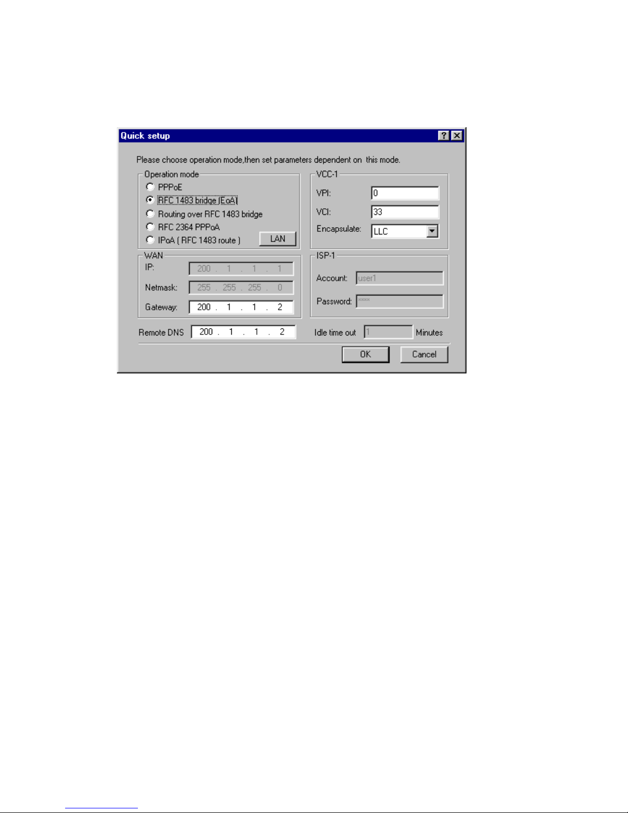
RFC 1483 bridge (EoA)
Bridged protocol data unit is encapsulated using RFC 1483 protocol
over an ATM network and this operation mode using ATM/ADSL to
execute as a Ethernet's bridge.
1. VPI: Enter the number of the virtual path identifier in the VPI
field.
The VPI is a number in the range 0-255. Consult your ATM transport
administrator for what number you should enter in this field.
2. VCI: Enter the number of the virtual circuit identifier in the VCI
field.
The VCI is a number in the range 0-65534. Consult your ATM
transport administrator for what number you should enter in this field.
3. Encapsulate: Select the encapsulation setting.
You choose LLC or VC Mux to configure whether the virtual circuit
uses LLC-SNAP encapsulation or Vc-based multiplexing.
4. Gateway: Use the Gateway Address field to specify the IP
address of the default IP gateway.
5. Remote DNS: Enter the IP address of your domain name server
in the Remote DNS field.
A domain name server is a network computer responsible for
matching host names to numeric IP addresses so that network traffic
can be routed correctly. Your Internet Service Provider can provide
the IP address of its domain name server.
Page 18

16
6. Click the OK button to store your modified configuration in
this ADSL router memory. Or click Cancel button to return to
main page.
Note: Please execute the actions of Save and Reboot to make the new
connection after configured the Quick Setup.
Page 19
17
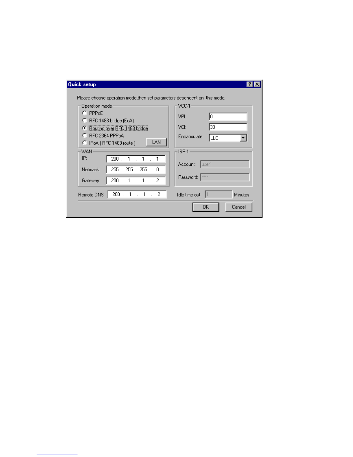
Routing over RFC 1483 bridge
Bridged protocol data unit is encapsulated using RFC 1483 protocol
over an ATM network and this operation mode use ATM/ADSL to
simulate as a Ethernet network router to route information between
LANs.
1. VPI: Enter the number of the virtual path identifier in the VPI
field.
The VPI is a number in the range 0-255. Consult your ATM transport
administrator for what number you should enter in this field.
2. VCI: Enter the number of the virtual circuit identifier in the VCI
field.
The VCI is a number in the range 0-65534. Consult your ATM
transport administrator for what number you should enter in this field.
3. Encapsulate: Select the encapsulation setting.
You choose LLC or VC Mux to configure whether the virtual circuit
uses LLC-SNAP encapsulation or Vc-based multiplexing.
4. IP: Enter the IP address the ADSL router will use on this
virtual circuit in the IP Address field.
The IP address you enter must not be in use by other devices on
this virtual circuit. The domain of Ip have to not same as LAN.
Page 20

18
5. Netmask: Enter the subnet mask for the network connected to
this virtual circuit in the Netmask field.
The subnet mask specifies which bits of the 32-bit binary IP address
represent network information. Most sites should use 255.255.255.0
for their subnet mask.
6. Gateway: Use the Gateway Address field to specify the IP
address of the default IP gateway.
7. Remote DNS: Enter the IP address of your domain name server
in the Remote DNS field.
A domain name server is a network computer responsible for
matching host names to numeric IP addresses so that network traffic
can be routed correctly. Your Internet Service Provider can provide
the IP address of its domain name server.
8. Click the OK button to store your modified configuration in
this ADSL router memory. Or click Cancel button to return to
main page.
Note: Please execute the actions of Save and Reboot to make the new
connection after configured the Quick Setup.
Page 21
19
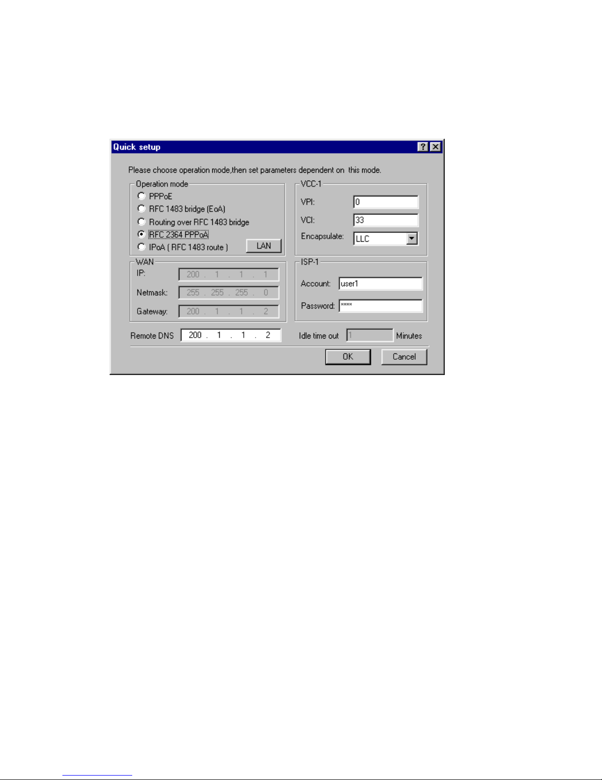
RFC 2364 PPPoA
The Framing PPP packet is encapsulated using RFC 2364 protocol
over an ATM network and this operation mode use PPP/ATM/ADSL to
make a PPP connection with ISP. The other side of PC or LAN can
follow this PPP connection to access Internet service.
1. VPI: Enter the number of the virtual path identifier in the VPI
field.
The VPI is a number in the range 0-255. Consult your ATM transport
administrator for what number you should enter in this field.
2. VCI: Enter the number of the virtual circuit identifier in the VCI
field.
The VCI is a number in the range 0-65534. Consult your ATM
transport administrator for what number you should enter in this field.
3. Encapsulate: Select the encapsulation setting.
You choose LLC or VC Mux to configure whether the virtual circuit
uses LLC-SNAP encapsulation or Vc-based multiplexing.
4. Account: Enter the account provided by your ISP in the Account
field.
5. Password: Enter the password provided by your ISP in the
Password field.
Page 22

20
6. Remote DNS: Enter the IP address of your domain name server
in the Remote DNS field.
A domain name server is a network computer responsible for
matching host names to numeric IP addresses so that network traffic
can be routed correctly. Your Internet Service Provider can provide
the IP address of its domain name server. In the case of PPP
connection, the remote access server will be assign this field
automatically. Unless you should fill it by manual.
7. Click the OK button to store your modified configuration in
this ADSL router memory. Or click Cancel button to return to
main page.
Note: Please execute the actions of Save and Reboot to make the new
connection after configured the Quick Setup.
Page 23
21
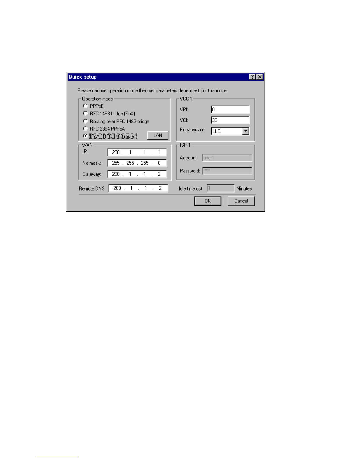
IPoA (RFC 1483 route)
The Routed protocol data unit is encapsulated using RFC 1483 protocol
over an ATM network and this operation mode connect and communicate
directly with Internet through ATM/ADSL.
1. VPI: Enter the number of the virtual path identifier in the VPI
field.
The VPI is a number in the range 0-255. Consult your ATM transport
administrator for what number you should enter in this field.
2. VCI: Enter the number of the virtual circuit identifier in the VCI
field.
The VCI is a number in the range 0-65534. Consult your ATM
transport administrator for what number you should enter in this field.
3. Encapsulate: Select the encapsulation setting.
You choose LLC or VC Mux to configure whether the virtual circuit
uses LLC-SNAP encapsulation or Vc-based multiplexing.
4. IP: Enter the IP address the ADSL router will use on this
virtual circuit in the IP Address field.
The IP address you enter must not be in use by other devices on
this virtual circuit. The domain of Ip have to not same as LAN.
5. Netmask: Enter the subnet mask for the network connected to
this virtual circuit in the Netmask field.
The subnet mask specifies which bits of the 32-bit binary IP address
represent network information. Most sites should use 255.255.255.0
for their subnet mask.
Page 24

22
6. Gateway: Use the Gateway Address field to specify the IP
address of the default IP gateway.
7. Remote DNS: Enter the IP address of your domain name server
in the Remote DNS field.
A domain name server is a network computer responsible for
matching host names to numeric IP addresses so that network traffic
can be routed correctly. Your Internet Service Provider can provide
the IP address of its domain name server.
8. Click the OK button to store your modified configuration in
this ADSL router memory. Or click Cancel button to return to
main page.
Note: Please execute the actions of Save and Reboot to make the new
connection after configured the Quick Setup.
Page 25
23
3. Advanced Configuration
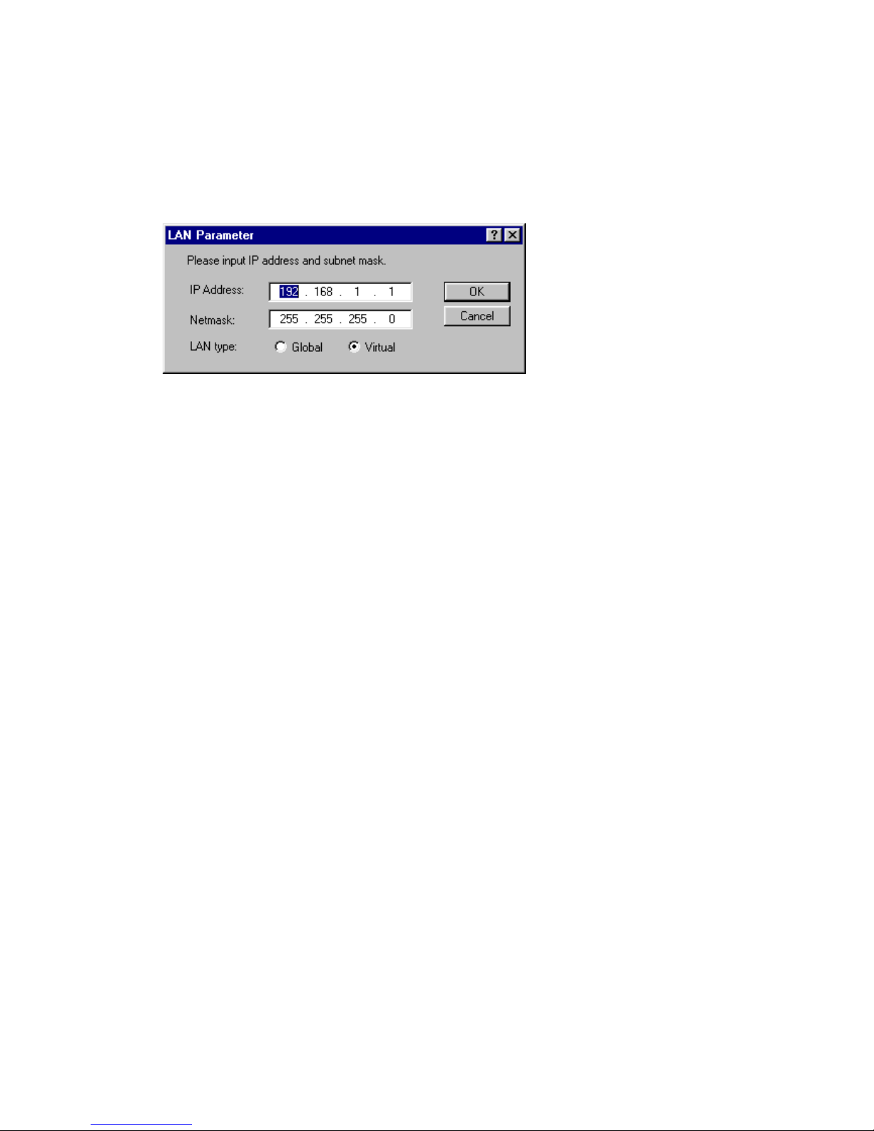
LAN
If you want to customize the settings for the Ethernet interface on your
router, enter or change following information in the LAN window.
IP Address The IP address of this router on the network connected
to its LAN interface.
Netmask The range of subnet mask in use for the LAN connected
to the Ethernet port. Default is 255.255.255.0
LAN type The IP address uses on the LAN is Virtual IP or
Global IP.
Virtual IP is just used on the LAN.
Global IP is used on the Internet.
Click the OK button to store your modified configuration in this
ADSL router memory. Or click Cancel button to return to main
page.
Page 26
24
DHCP
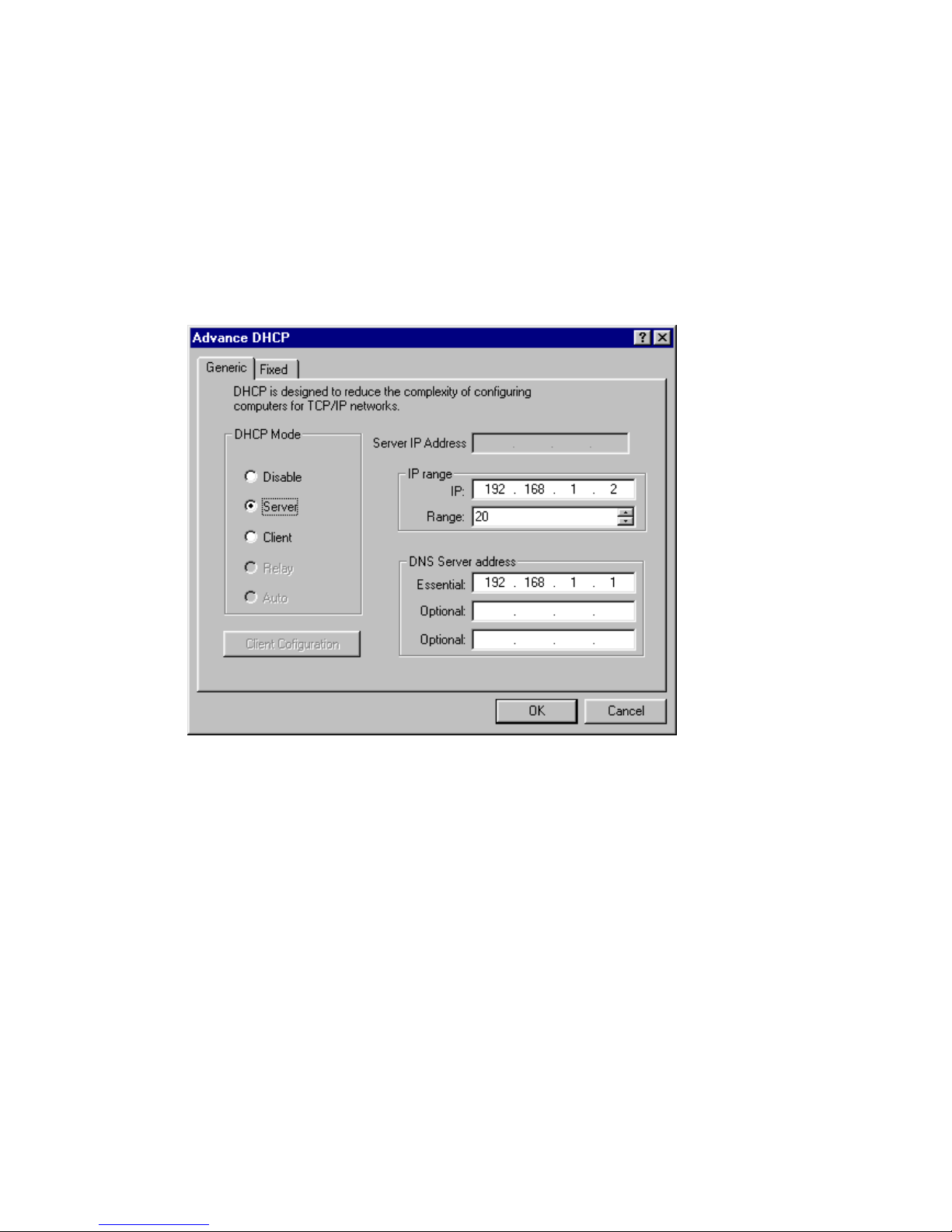
Dynamic Host Configuration Protocol (DHCP) is most used on LAN to
manage IP on each host, specifically used on Virtual IP environment.
In DHCP Server mode, this router automatically assign IP settings to
a workstation on your LAN.
Generic Configure DHCP mode and related parameters in the
router.
1. DHCP Mode: Click Disable to turn off the DHCP service or
select Server/Client.
Server Mode:
If you select Server, for small home LANs it might be interesting
to configure all you PCs as DHCP Clients and the A400A as
DHCP Server. In this configuration each time a computer boots,
it will obtain its IP configuration from the A400A.
Page 27
25
2. IP: Specify the first address from the DHCP client. It should
be within the same subnet you have configured on your LAN
and should not be the same IP address on LAN.
3. Range: Enter a number in the range 1-254.
4. Essential: The IP address of the essential DNS name server
for your network.
5. Optional: Enter optional IP address of DNS server on DHCP
client.
6. Click the OK button to store your modified configuration in
this ADSL router memory. Or click Cancel button to return to
main page.
Client Mode:
If you select Client, for advanced networks, the role of DHCP
Server might be performed by an IP node other than the A400A
on the local LAN. Typically such functions are attributed to Home
Gateways: computers having better networking capabilities than
the other hosts on the home LAN.
All local PCs remain configured as DHCP Clients, including the
A400A.
Note: After you change DHCP mode from "Disable/Server" to "DHCP
Client mode" and if you would like to active this setting immediately
you must execute the functionality of "Save" and "Reboot" at first,
after this procedure you just can enter the window of Client
Configuration and execute related configuration.
Page 28

26
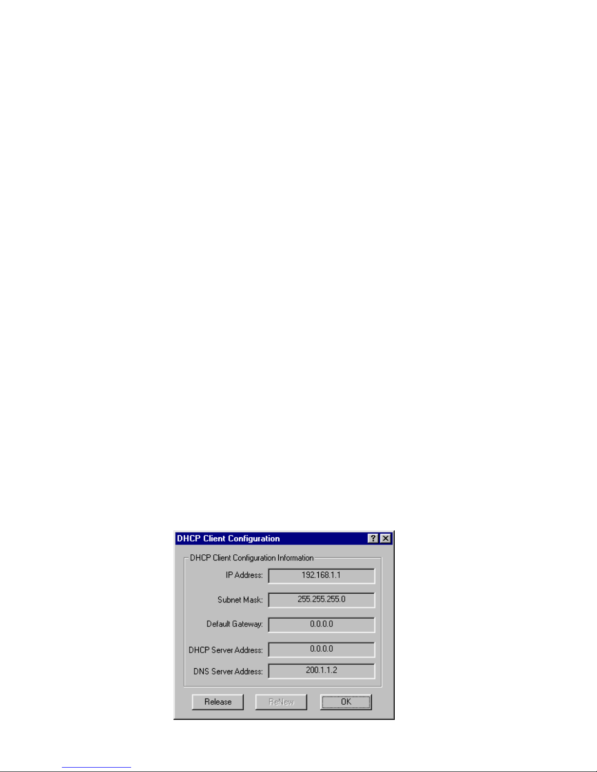
In DHCP Client mode, you can get IP address and related information
for this router from DHCP server.
1. IP Address: The IP address of the device
2. Subnet mask: The Subnet mask of the device.
3. Default Gateway: The default gateway of the device.
4. DHCP Server Address: The IP address of your DHCP Server.
5. DNS Server Address: The IP address of your DNS Server.
6. Release button: Before you start to get a new IP address, you
must release the old configuration.
7. Renew button: Start to get IP address and some information
from DHCP Server.
8. Click OK button to complete the DHCP Client Configuration
and return to previous window.
Page 29
27
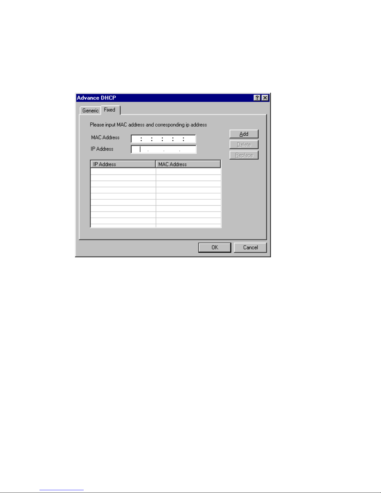
Fixed You can assign some correspondence Mac Address to
some fixed IP. Please input Mac address and
corresponding IP address. After you click the Add button,
your setting is shown in the table below. You can add
new information or delete unused one in the table.
Click Add button to save information. The configuration page adds a
new row to show this setting. You can click Delete button to delete a
chosen setting. Or you can click Replace button to replace original
setting.
Click the OK button to store your modified configuration in this ADSL
router memory. Or click Cancel button to return to main page.
Page 30
28
IP Sharing
Usually for the home user or the SOHO user, you only can apply one
or a few Internet IP Addresses which sometimes are not enough for
many hosts on the LAN to access Internet service at the same time.
This function provide the solution for such problem.
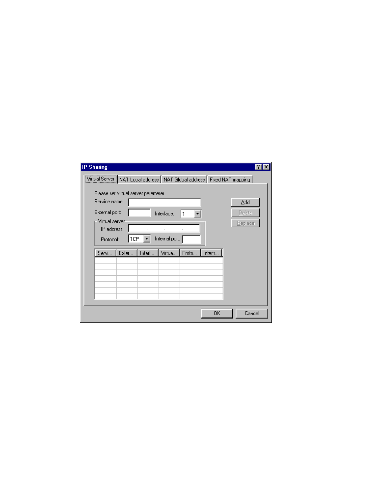
Virtual Server
The ADSL router can set up different functions server on the different
host site of LAN through one Internet IP address.
NAT (Network Address Transfer)
NAT can correlate virtual IP/Global IP in static or dynamic way.
1. Service name: Enter a name for virtual server.
2. External port: Enter the port number which is correspond to
the Global IP on virtual server.
3. Interface: Use the dropdown menu to select a number from 1
to 8 (please refer the settings in ATM & VC service mode).
4. IP address: Enter the IP address you want to enable for virtual
server.
5. Protocol: Use the dropdown menu to select the Protocol (TCP
or UDP) of virtual server service.
Page 31

29
6. Internal port: Enter the port number your virtual server service
use.
The range of this field is 0 to 65534.
7. Click Add button to save information. The configuration page
adds a new row to show this setting. You can click Delete
button to delete a chosen setting. Or you can click Replace
button to replace original setting.
8. Click the OK button to store your modified configuration in
this ADSL router memory. Or click Cancel button to return to
main page.
Page 32
30
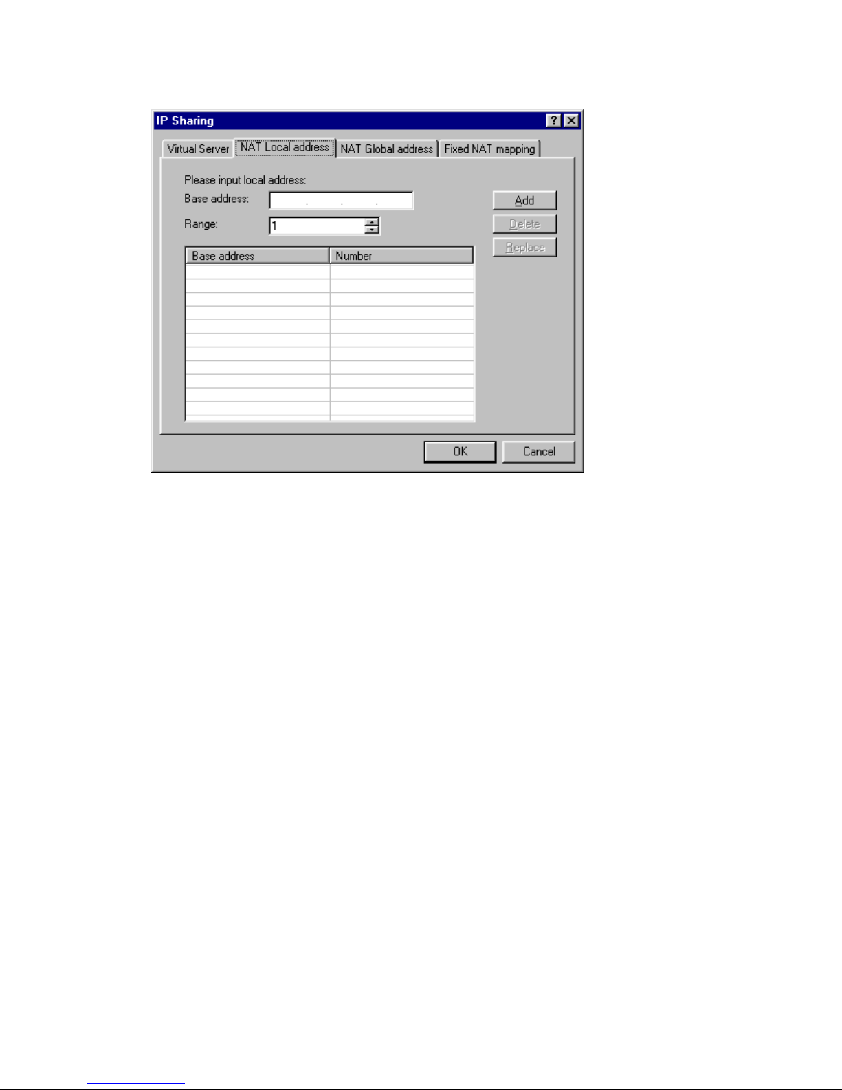
NAT Local address
1. Base address: Enter the local (virtual) IP address you want to
enable for address translation.
2. Range: Enter the number of local (virtual) address.
3. Click Add button to save information. The configuration page
adds a new row to show this setting. You can click Delete
button to delete a chosen setting. Or you can click Replace
button to replace original setting.
4. Click the OK button to store your modified configuration in
this ADSL router memory. Or click Cancel button to return to
main page.
Page 33
31
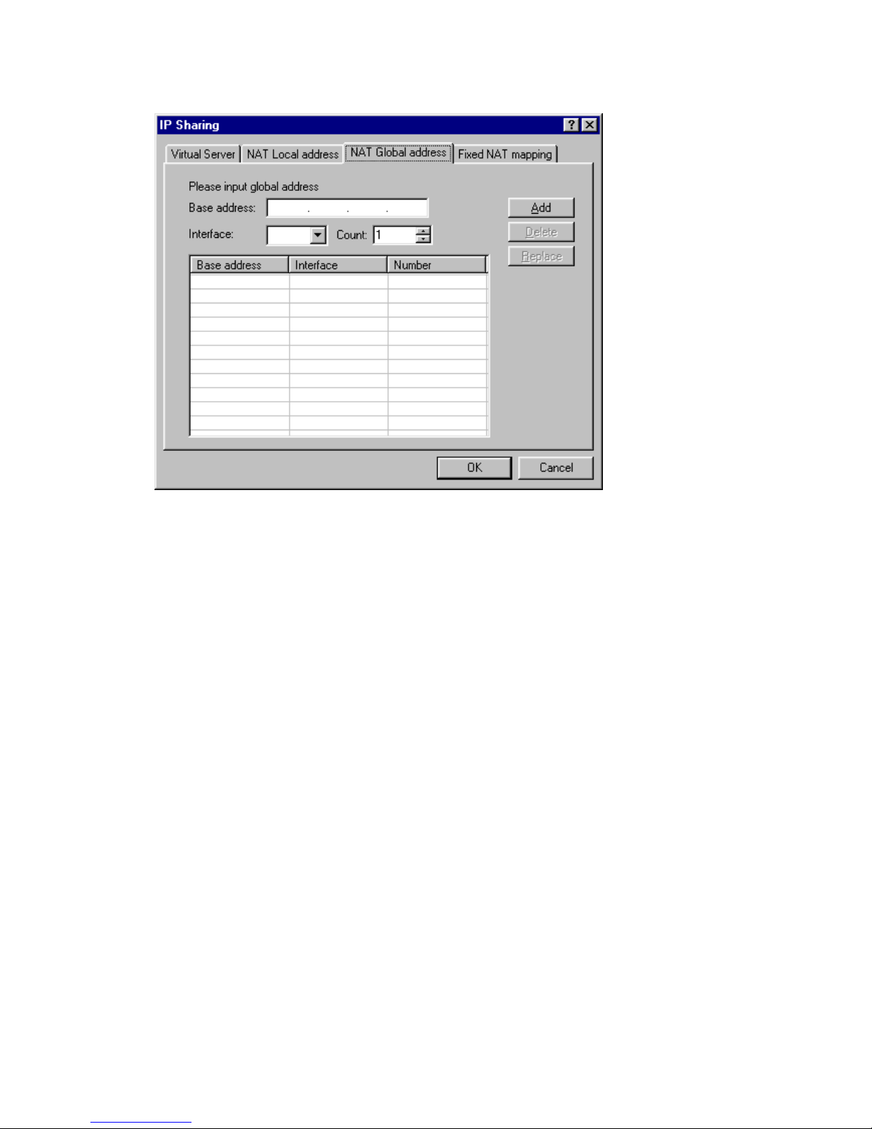
NAT Global address
1. Base address: Enter the global IP address you want to enable
for address translation.
2. Interface: Use the dropdown menu to select a number from 1
to 8 (please refer the settings in ATM & VC service mode).
3. Count: Enter the number of global address.
4. Click Add button to save information. The configuration page
adds a new row to show this setting. You can click Delete
button to delete a chosen setting. Or you can click Replace
button to replace original setting.
5. Click the OK button to store your modified configuration in
this ADSL router memory. Or click Cancel button to return to
main page.
Page 34
32
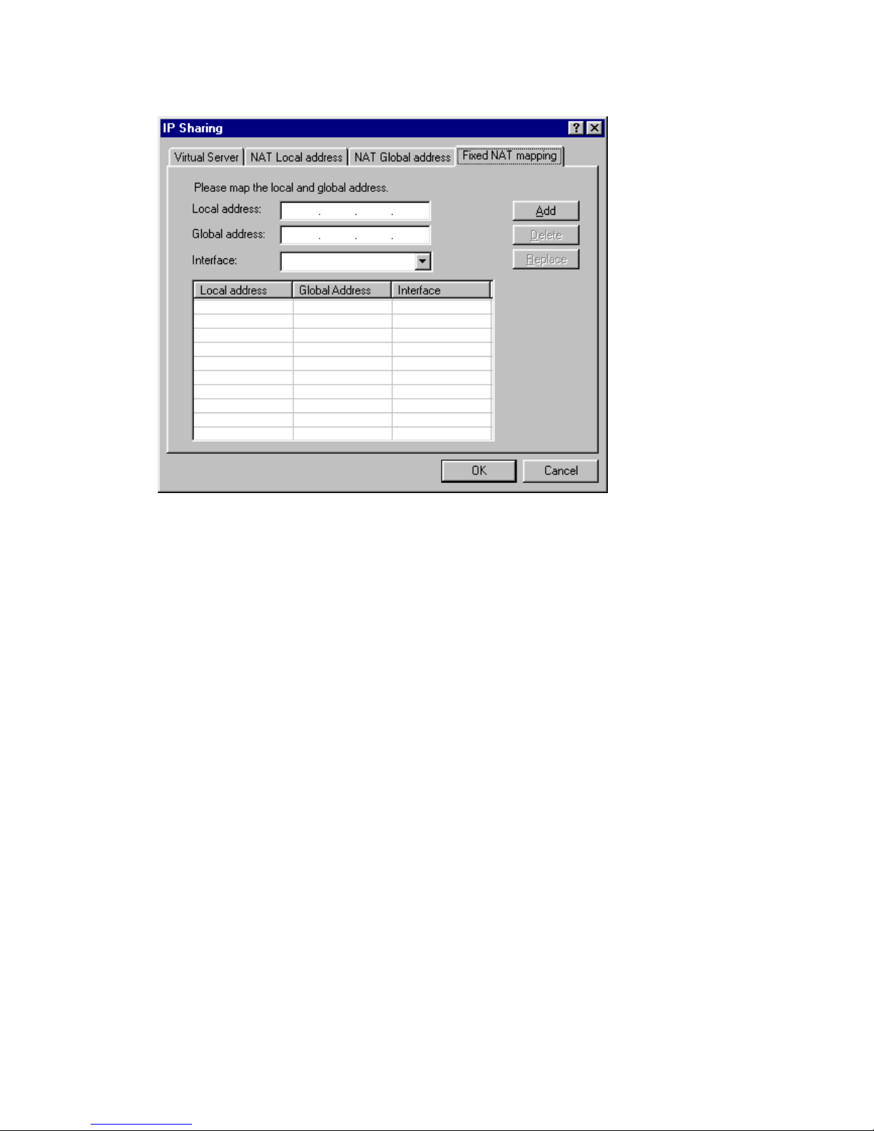
Fixed NAT mapping
1. Local address: Enter the local (virtual) IP address you want to
enable for fixed address translation mapping.
2. Global address: Enter the global address which is
corresponded to local address.
3. Interface: Use the dropdown menu to select a number from 1
to 8 (please refer the settings in ATM & VC service mode).
4. Click Add button to save information. The configuration page
adds a new row to show this setting. You can click Delete
button to delete a chosen setting. Or you can click Replace
button to replace original setting.
5. Click the OK button to store your modified configuration in
this ADSL router memory. Or click Cancel button to return to
main page.
Page 35
33
Routing Protocol (RIP)
RIP sends routing-update messages at regular intervals and when the
network topology changes. When a router receives a routing update that
includes changes to an entry, it updates its routing table to reflect the
new route. RIP routers maintain only the best route (the route with the
lowest metric value) to a destination.
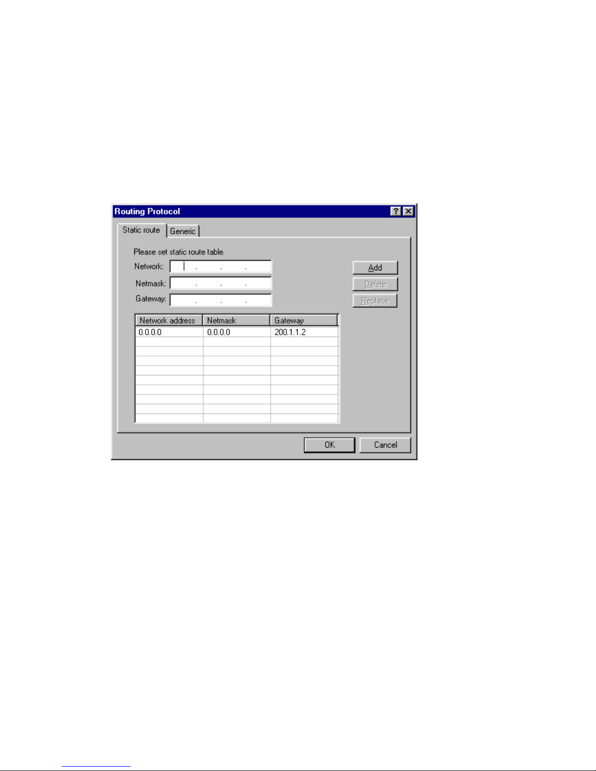
Static Route You can set up static route table for some fixed
domain address path.
1. Network: Specify the destination host.
2. Netmask: Specify a subnet mask value to be associated with
this route entry.
The subnet mask specifies which bits of the 32-bit binary IP address
represent network information. Most sites should use 255.255.255.0
for their subnet mask.
3. Gateway: Use the Gateway Address field to specify the IP
address of the default IP gateway.
4. Click Add button to save information. The configuration page
adds a new row to show this setting. You can click Delete
button to delete a chosen setting. Or you can click Replace
button to replace original setting.
5. Click the OK button to store your modified configuration in
this ADSL router memory. Or click Cancel button to return to
main page.
Page 36
34
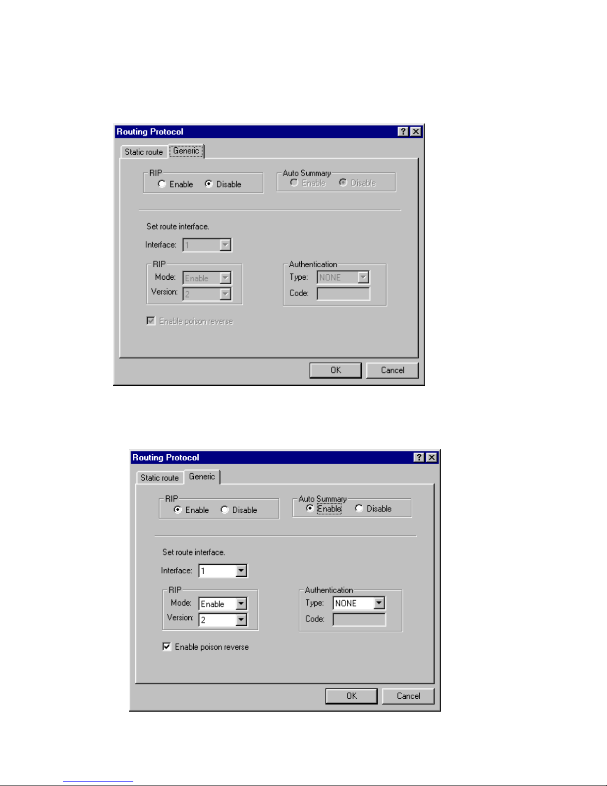
Generic Specifies a number of stability features. To adjust for
rapid network-topology changes and prevents routing
loops from continuing indefinitely, to have a faster and
safer routing.
1. RIP: Click Enable to turn on RIP service and go to step 2. If
not, click OK/Cancel button to return to main page.
Page 37

35
2. Interface: Use the dropdown menu to select a number from 1
to 8 (please refer the settings in ATM & VC service mode).
3. Mode: Use the dropdown menu to select the mode.
Options are:
Disable: Select Disable to turn off RIP service for the certain
interface.
Enable: Select Enable to turn on RIP service for the certain
interface.
Silent: Select Silent for receiving routing information only.
4. Version: Use the dropdown menu to select the version.
RIP-Send/receive specify whether you want the router to send Routing
Information Protocol (RIP) messages to other routers.
Option are:
RIP-1 - Broadcast/Accept routing information in RIP version 1
format.
RIP-2- Multicast/Accept routing information in RIP version 2
format.
5. Type: Use the drop down menu to specify whether the router
accepts administrative commands received over this virtual
circuit.
Options are: NONE, PASSWORD, MD5
6. Code: Enter the password (up to 15 characters) when you
select the type of PASSWORD or MD5 on above step 5.
7. Enable poison reverse: When network topology change,
especially for this router detect some route disappear, this
router will keep routing information from being used for a
period of time and notify its unlimited distance to other
communication servers.
8. Click the OK button to store your modified configuration in
this ADSL router memory. Or click Cancel button to return to
main page.
Page 38
36
ISP (Internet Service Provider)
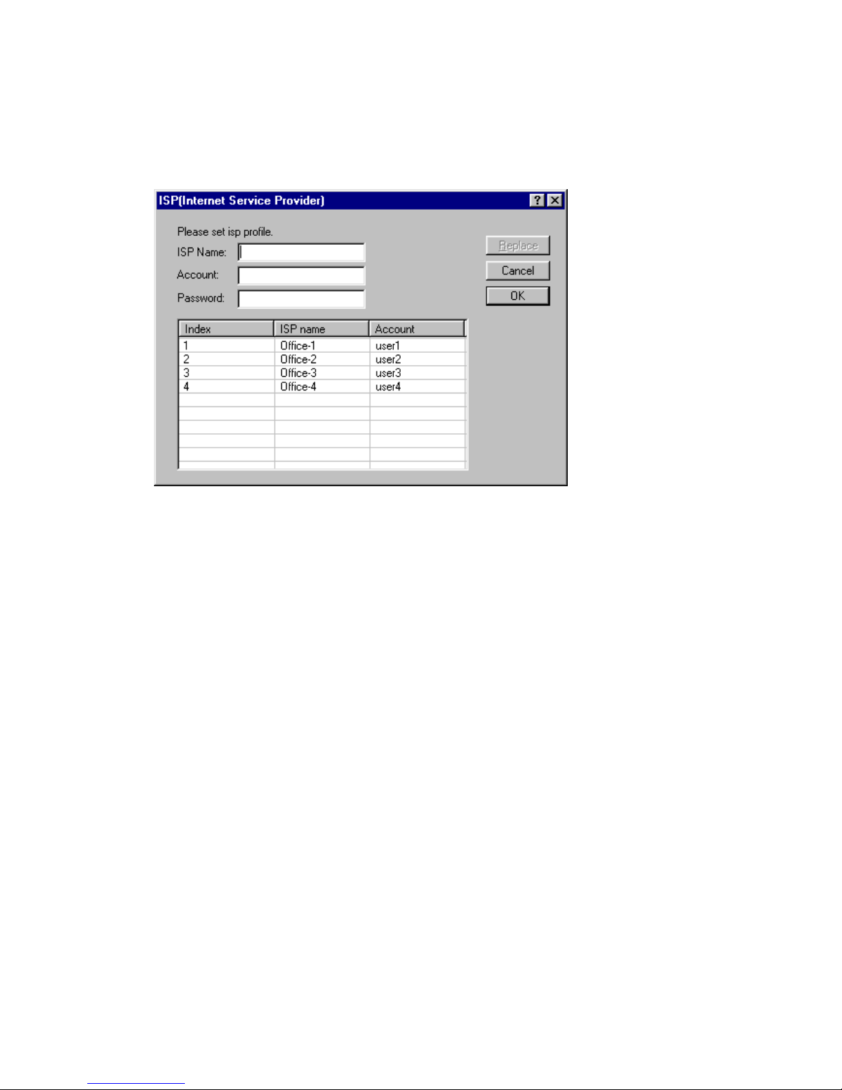
If you have several ISP accounts, you can input the related information
of each ISP on this window. It can let you change ISP access
conveniently or proceed the configuration when access simultaneously.
Select a ISP name, make necessary change, then click Replace button
to replace original setting.
Click the OK button to store your modified configuration in this ADSL
router memory. Or click Cancel button to return to main page.
Page 39
37
Spanning Tree
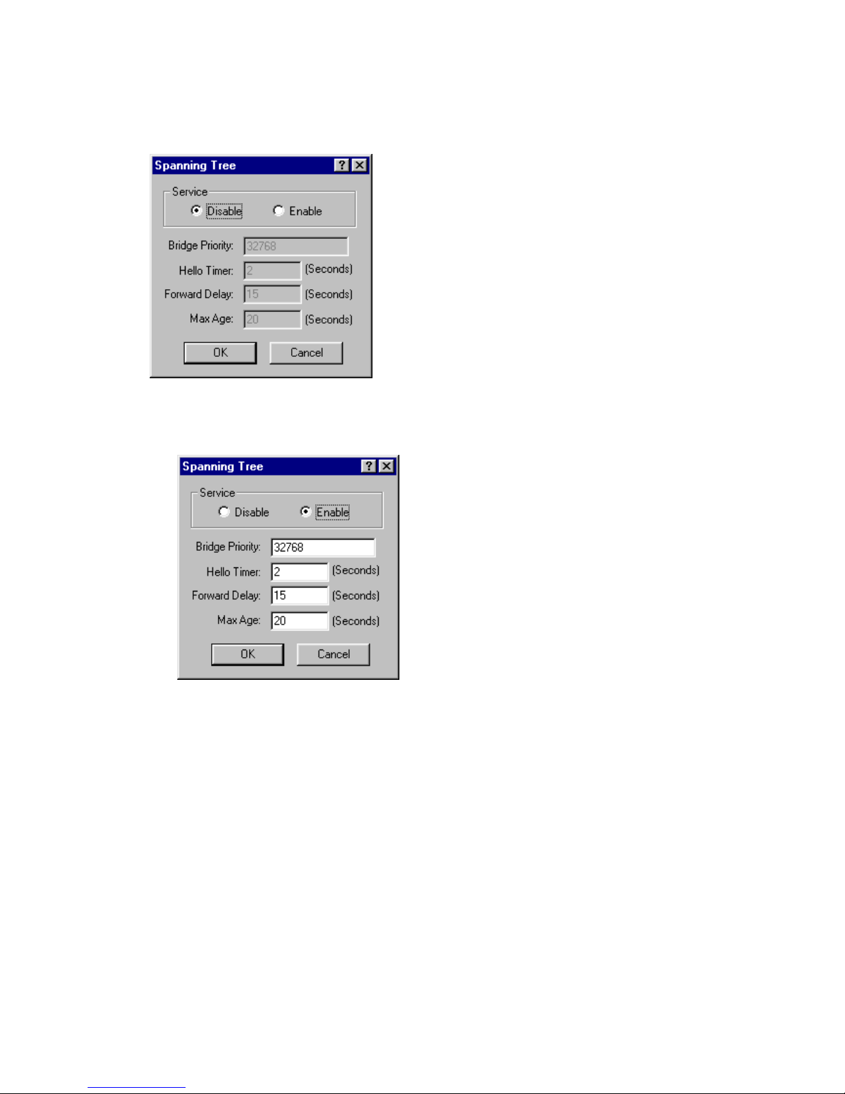
The Spanning Tree algorithm that is used to avoid packet looping in
your network.
1. Service: Click Enable to turn on spanning tree service and go
to step 2. If not, click OK/Cancel to return main page.
2. Bridge Priority: Enter the value of root bridge, the range of
this field is 0 to 65535.
Each bridge has its own identification code. The code can be used
to decide which bridge will be the root bridge. The bridge with
smallest identification code will be the root bridge.
3. Hello Timer: Enter the timing interval which root bridge will
produce a communication frame.
4. Forward Delay: Enter the longest timing that a communication
frame is transmitted/received through all bridges.
5. Max Age: Enter the existing timing of each communication
frame.
6. Click the OK button to store your modified configuration in
this ADSL router memory. Or click Cancel button to return to
main page.
Page 40
38
SNMP
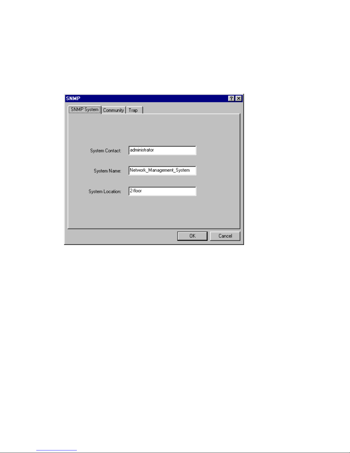
The Simple Network Management Protocol (SNMP) lets a network
administrator monitor problems on a network by retrieving settings on
remote network devices. Network administrator typically runs an SNMP
management station program such as MIB browser on a local host to
obtain information from an SNMP agent such as the A400A.
1. System Contact: Enter information about the system contact
person in the System Contact field.
For example, you might enter the email address of the person
responsible for the A400A.
2. System Name: Enter information about the system name in
the System Name field.
For example, you might enter the administratively-assigned name for
the A400A.
3. System Location: Enter information about the system location
in the System Location field.
For example, you might enter the physical location of this node such
as building, floor, or room number where the A400A is located.
4. Click the OK button to store your modified configuration in
this ADSL router memory. Or click Cancel button to return to
main page.
Page 41
39
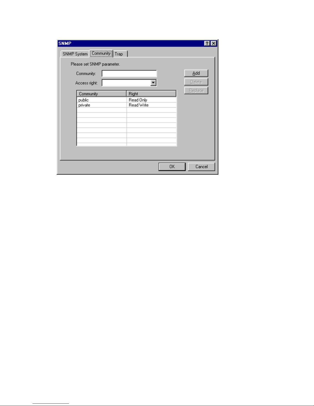
Community tab
1. Community: Identify the SNMP communities to which the A400A
belongs by entering a community name in the Community
Field.
By default, the A400A is associated with the public community. You
can associate as many as 5 communities with the A400A.
2. Access right: Use drop down menu to select the access right
from read only, read/write or deny under this community name.
3. Click Add button to save information. The configuration page
adds a new row to show this setting. You can click Delete
button to delete a chosen setting. Or you can click Replace
button to replace original setting.
4. Click the OK button to store your modified configuration in
this ADSL router memory. Or click Cancel button to return to
main page.
Page 42
40
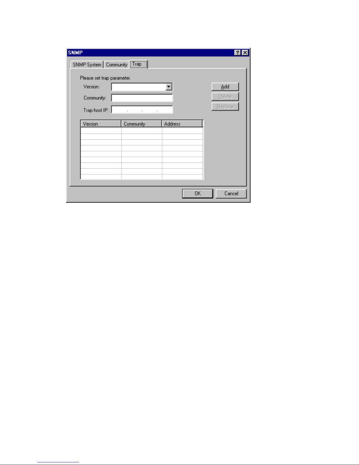
Trap tab
1. Version: Use drop down menu to select the version.
2. Community: Enter the name of the community for which the
trap destination is responsible in the Community field.
3. Trap host IP: Enter the IP address of a host acting as an
SNMP console which A400A should send SNMP trap messages
in the Trap host Ip filed.
4. Click Add button to save information. The configuration page
adds a new row to show this setting. You can click Delete
button to delete a chosen setting. Or you can click Replace
button to replace original setting.
5. Click the OK button to store your modified configuration in
this ADSL router memory. Or click Cancel button to return to
main page.
Page 43
41
ATM Interface & VCs
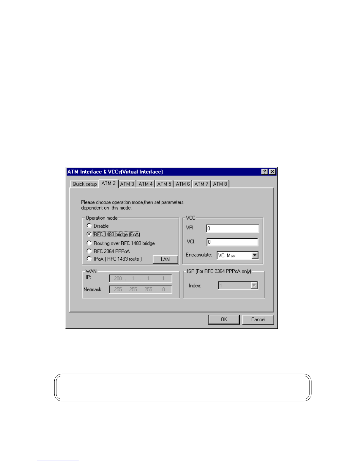
This ADSL router connect/communicate with WAN via ATM/ADSL. In
the ATM structure, this ADSL router has VC (Virtual Circuit) function and
It can set up one or several Virtual Interfaces to proceed connection/
communication individually or simultaneously.
You can configure ATM settings for each virtual circuit. The selection
made for one virtual circuit does not affect other virtual circuits. The
screen that appears depends on the operation mode you selected.
The information you want to configure on each interface is supplied by
your ISP, the content is same as Quick Setup. Please refer to page
12 the instruction of Quick Setup.
Click the OK button to store your modified configuration in this ADSL
router memory. Or click Cancel button to return to main page.
Note:If you would like to configure the router as multi-VCC, these VCCs will
share your modem bandwidth. Please be careful with your application
Page 44
42
4. Special Function
Packet Filter
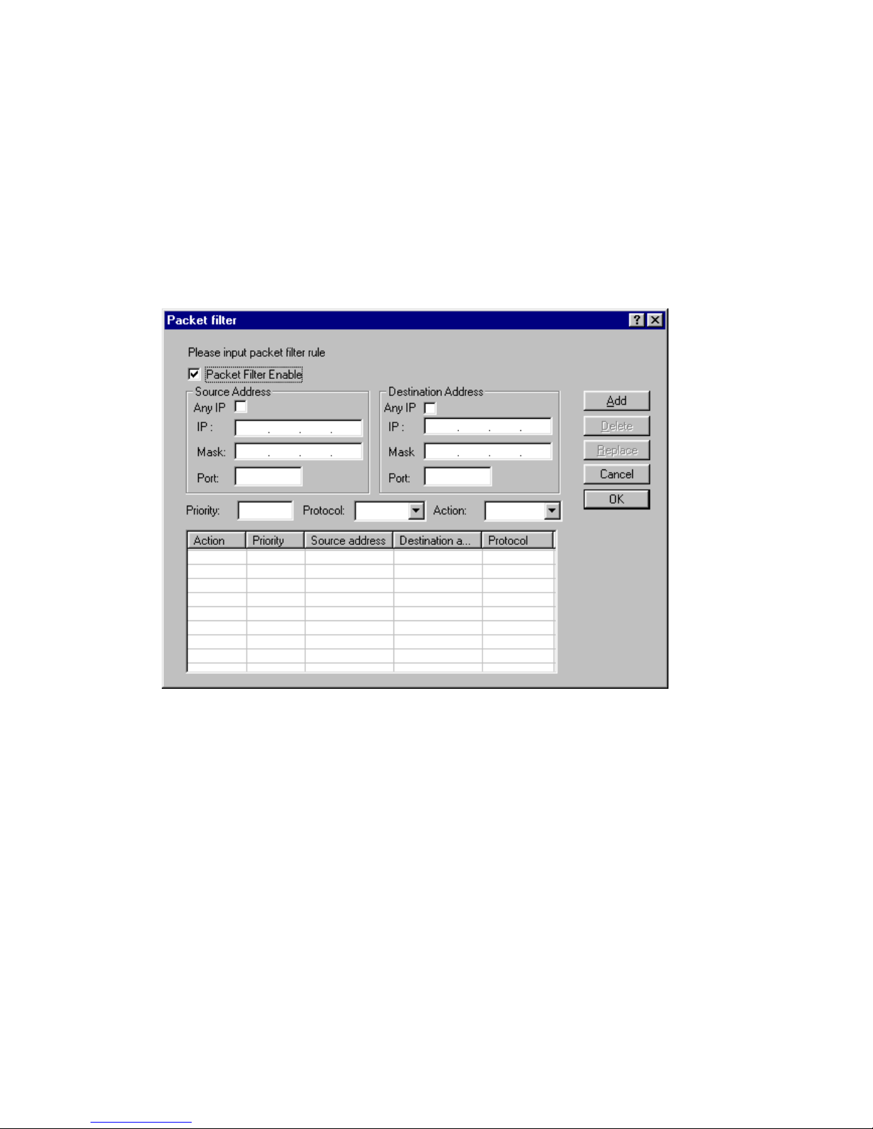
This ADSL router provides a simple protection against those unwanted
information/data from passing through LAN to WAN or WAN to LAN.
To limit some hosts on the LAN to access Internet service.
To limit some source from Internet to enter the LAN.
1. Packet Filter Enable: Click here to turn on packet filter service.
If not, please return to main page.
2. Any ip on Source Address session: Click here to define every
data packet from source address to be in the same priority/
protocol/action.
3. Or you can restrict certain IP address to deny internet service
or access it. Enter the restricted IP address in the IP field and
related information (Mask, Port) in the Mask and Port fields.
4. Any ip on Destination Address session: Click here to define
every data packet from source address to be in the same
priority/protocol/action.
Page 45

43
5. Or you can restrict certain IP address to deny the LAN or
enter it. Enter the restricted IP address in the IP field and
related information (Mask, Port) in the Mask and Port fields.
6. Priority: Enter a number to specify the priority of this rule. 1
is the highest and 65534 is the lowest.
7. Protocol: Enter the protocol that the rule used.
8. Action: You can choose to allow the data packet which you
chose to deny internet service or access it.
9. Click Add button to save information. The configuration page
adds a new row to show this setting. You can click Delete
button to delete a chosen setting. Or you can click Replace
button to replace original setting.
10. Click the OK button to store your modified configuration in
this ADSL router memory. Or click Cancel button to return to
main page.
Page 46
44
5. Maintenance
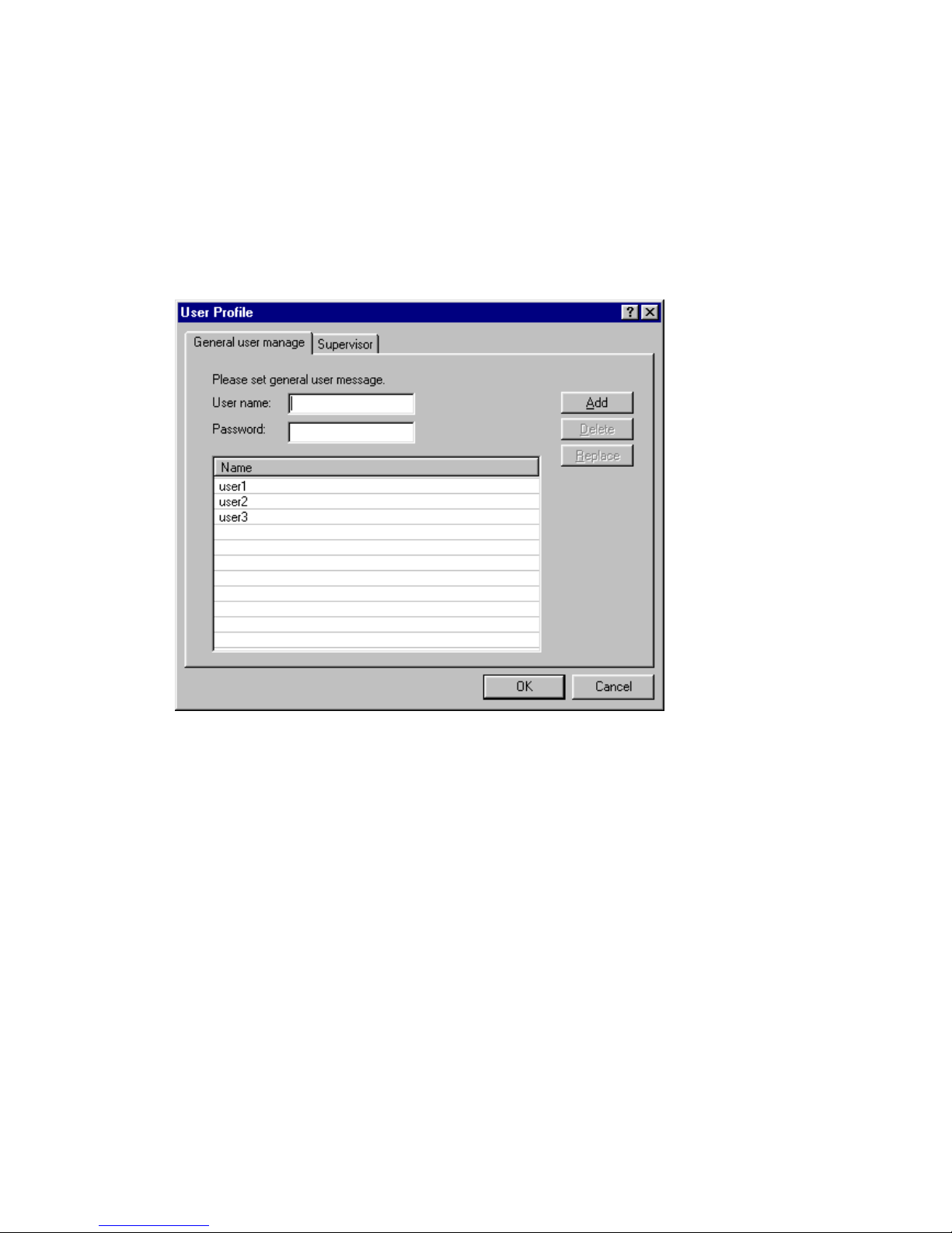
User Profile
This item provides you to manage each user's information and the limit
of authority. This ADSL router let different users configure the
parameters for different level according to the limit of authority.
General user manage
Click Add button to save information. The configuration page
adds a new row to show this setting. You can click Delete button
to delete a chosen setting. Or you can click Replace button to
replace original setting.
Click the OK button to store your modified configuration in this
ADSL router memory. Or click Cancel button to return to main
page.
Page 47
45
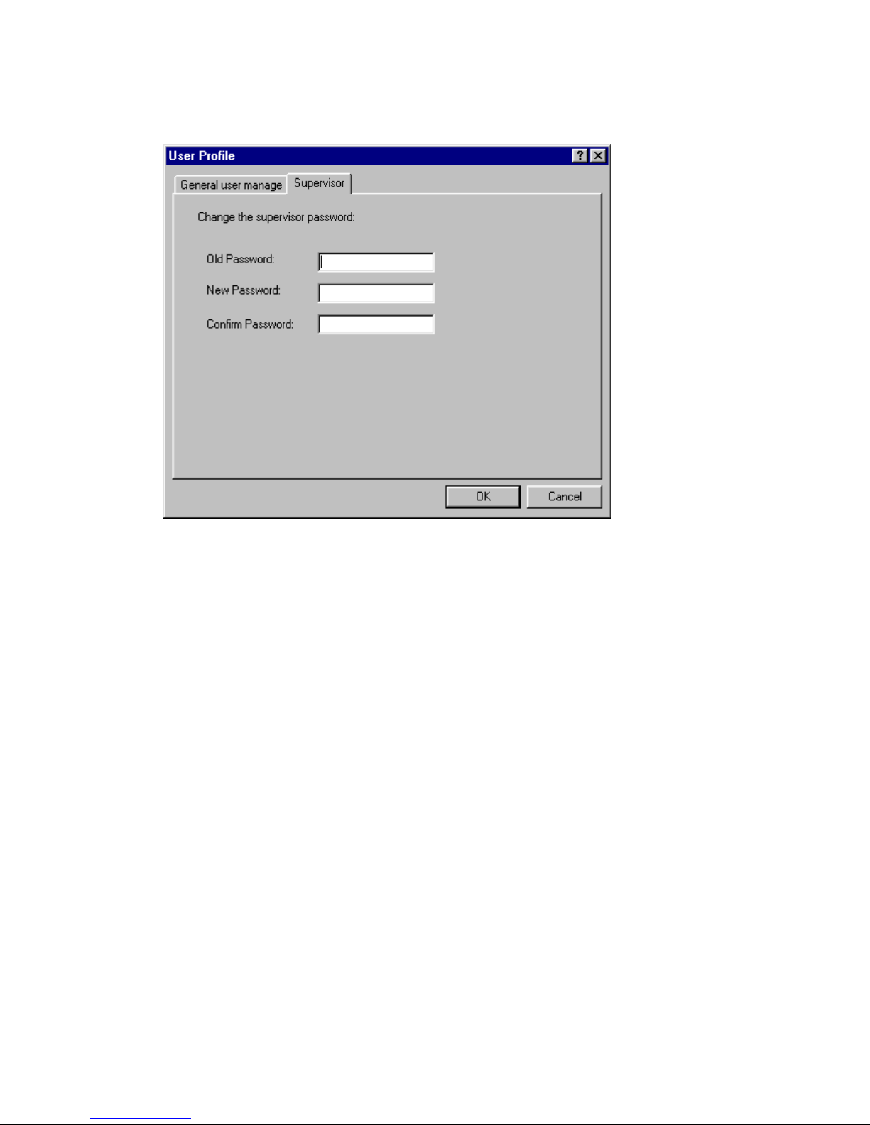
Supervisor tab
You may click Supervisor button to change the supervisor password.
Page 48
46
Monitor
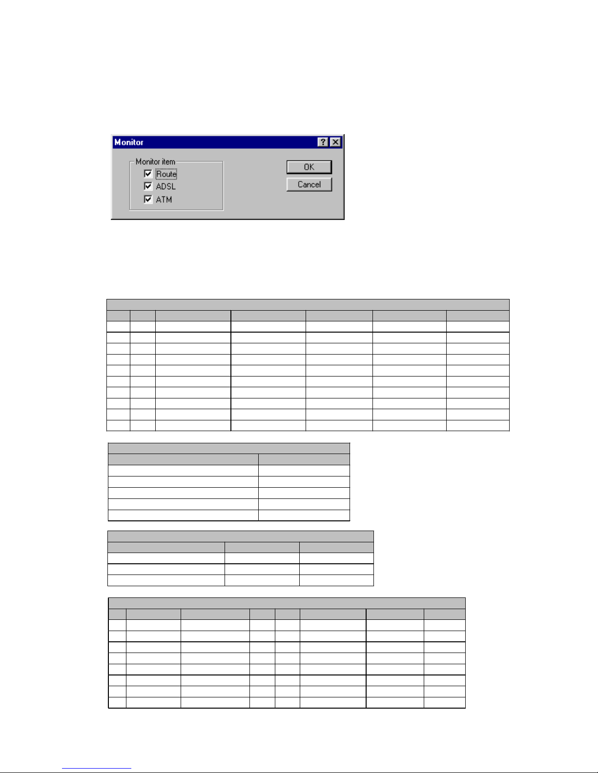
This item provides the current information about the operation of ADSL
router and there are three options (Route, ADSL and ATM) for you to
monitor.
Click the OK button to start monitoring selected items, and the status
will display in tables on right side of main page. Or click Cancel button
to return to main page.
Routing table
No. Type Network Address Netmask Gateway Interface Port Name
1 C 192.168.1.0 255.255.255.0 192.168.1.0 192.168.1.0 IF0
2 C 127.0.0.1 255.255.255.255 127.0.0.1 127.0.0.1 Loopback
3
4
5
6
7
8
9
10
ADSL Generic
Name Result
Buid-in Diagnostic Test Successful
DME Register Read/Write Test Successful
SW Status R-QUIET
Init Status Successful
C-ACT-REQ Not Detected
ADSL Bit Rate
Item Actual(kbps) Max(kbps)
Up Stream Duplex 0 0
Down Stream Duplex 0 0
Down Stream Simplex 0 0
ATM
No. IP Address Netmask VPI VCI Encapsulation Link Type Status
1 192.168.1.1 255.255.255.0 0 33 LLC Ethernet Down
2
3
4
5
6
7
8
Page 49
47
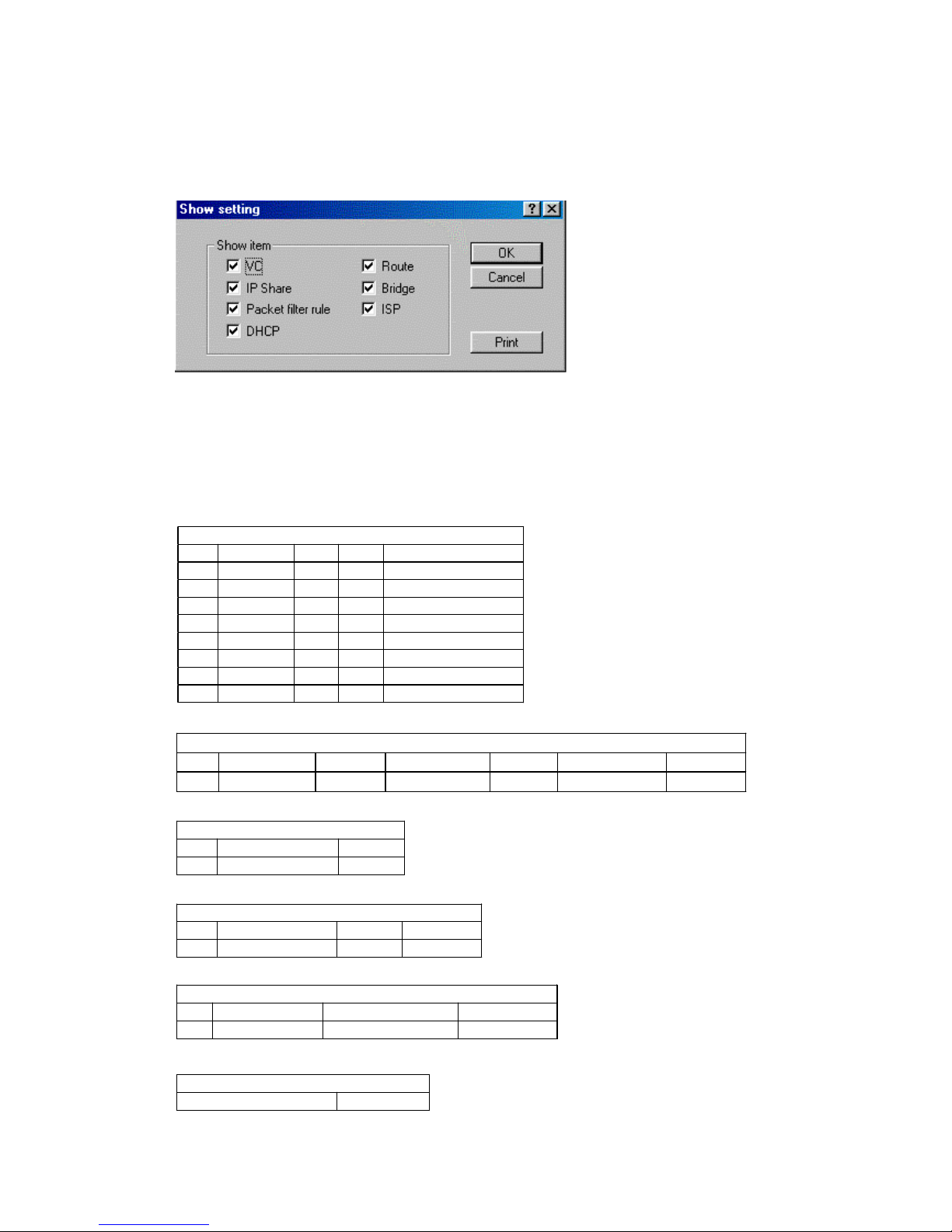
Show Setting
This item provides a summary of some function configurations, you may
get the information you want quickly or print the information.
Click the OK button to show the parameters tables of those items that
you selected on your right side of main page. Or click Cancel button
to return to main page. Click Print button to print out the data.
VC
No. Status VPI VCI Encapsulation
1 Enable 0 33 LLC
2 Disable 0 0 VC_Mux
3 Disable 0 0 VC_Mux
4 Disable 0 0 VC_Mux
5 Disable 0 0 VC_Mux
6 Disable 0 0 VC_Mux
7 Disable 0 0 VC_Mux
8 Disable 0 0 VC_Mux
Virtual Server Mapping
No. Serve Name Protocol External Port Host IP Internal Port Interface
1
NAT Local Address Range
No. Base Address Range
1
NAT Global Address Range
No. Base Address Count Interface
1
Fixed NAT Mapping
No. Local Ad dress Global Address Interface
1
Packet Filter Modu le
Packet Filter Module Enable
Page 50

48
Packet Filter Rule
No. Priority Action Protocol
Source
Address
Source
Mask
Source
Port
Destination
Address
Destination
Mask
Destination
Port
1
Generic DHCP Parameters
Server Enable
Default Gateway 192.168.1.1
Subnet Mask 255.255.255.0
DHCP Start IP 192.168. 1.2
DHCP IP Count 20
Name Server IP 192.168.1.1
Name Server IP
Name Server IP
Fixed Host Entries
No. IP Address Ethernet Address
1
Static Route
No. Network Address Netmask Gateway Address
1 0.0.0.0 0.0.0.0 200.1.1.2
RIP
RIP Mode Disable
Auto Summary Disable
Interface RIP parameter
Interface Mode RIP Version Authentication Poison Reverse Authenticate code
1 Enable 2 None Enable ***************
2 Disable 1 None Disable ***************
3 Disable 1 None Disable ***************
4 Disable 1 None Disable ***************
5 Disable 1 None Disable ***************
6 Disable 1 None Disable ***************
7 Disable 1 None Disable ***************
8 Disable 1 None Disable ***************
Generic Bridge Param et er
Bridge Function Enable
IP Address 192.168.1.1
Netmask 255.255.255.0
ISP
No. ISP Name User Account User Password
1 Office-1 user1 ***************
2 Office-2 user2 ***************
3 Office-3 user3 ***************
4 Office-4 user4 ***************
Page 51
49
F/W Upgrade
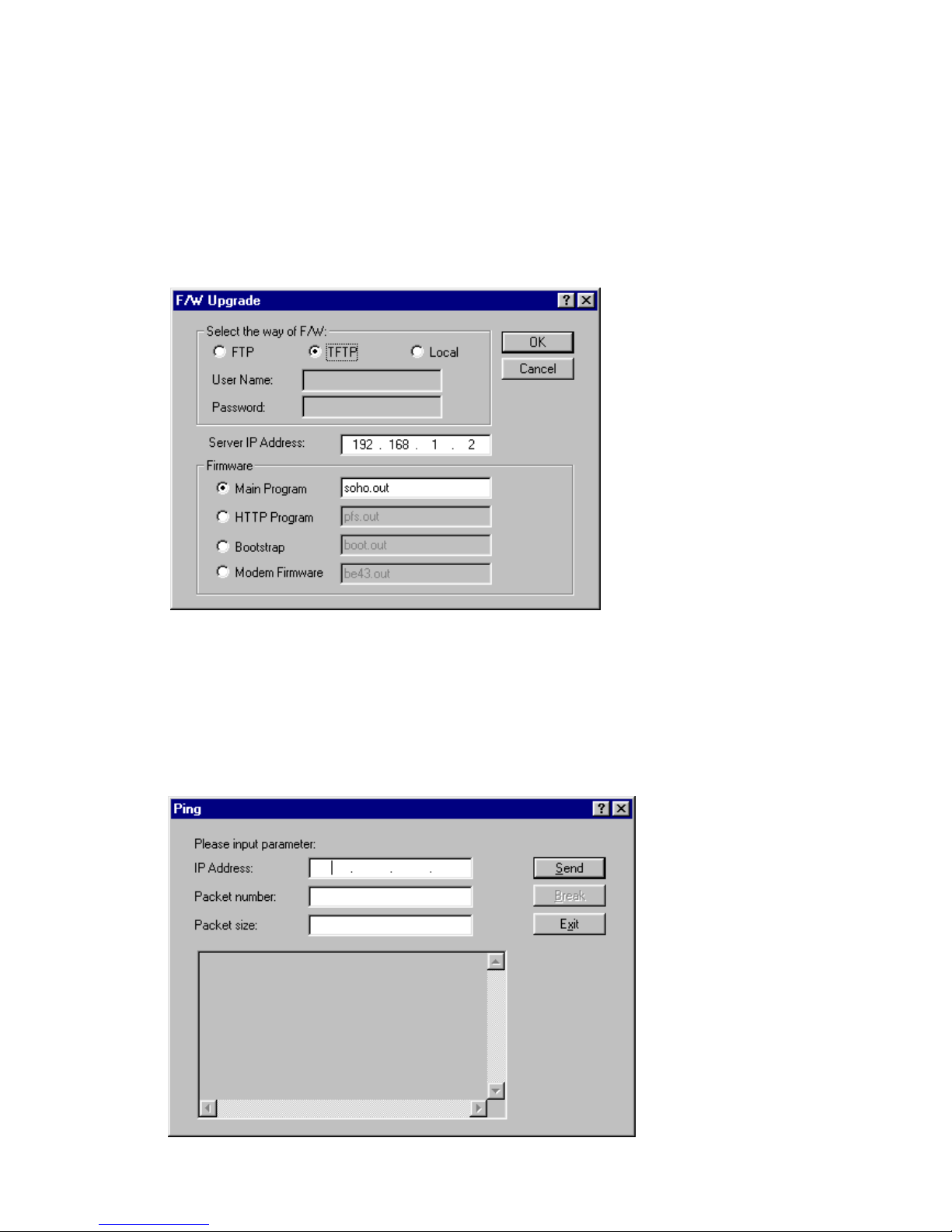
You can install new firmware in the router from any computer capable
of functioning as a Trivial File Transfer Protocol (TFTP) server or FTP
Server. If the firmware has been stored in your PC hard disk, you can
use local F/W upgrade, too.
This function is used for maintenance. Please proceed carefully when
install new F/W.
Ping
It is a sub set of the general command same as Ping utility. It is used
to detect whether this ADSL router is connected/communicated with
other network or not.
Page 52
50
Save configuration to file & Restore configuration
from file
These two utilities are especially for system backup. When you have
configured the system parameters. You can save it to file, and restore
it into system if necessary in future.
Reset to Default
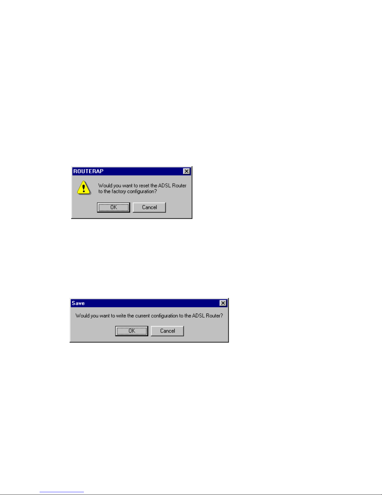
When the configuration of system parameters becomes in disorder/
confused, you may choose to let system parameters reset to start-up
default or reset to factory default.
Save
All of your configurations are stored temporarily in the system. If you
want to keep these configurations after the device reboot, you have to
execute this item.
Page 53
51
Reboot System
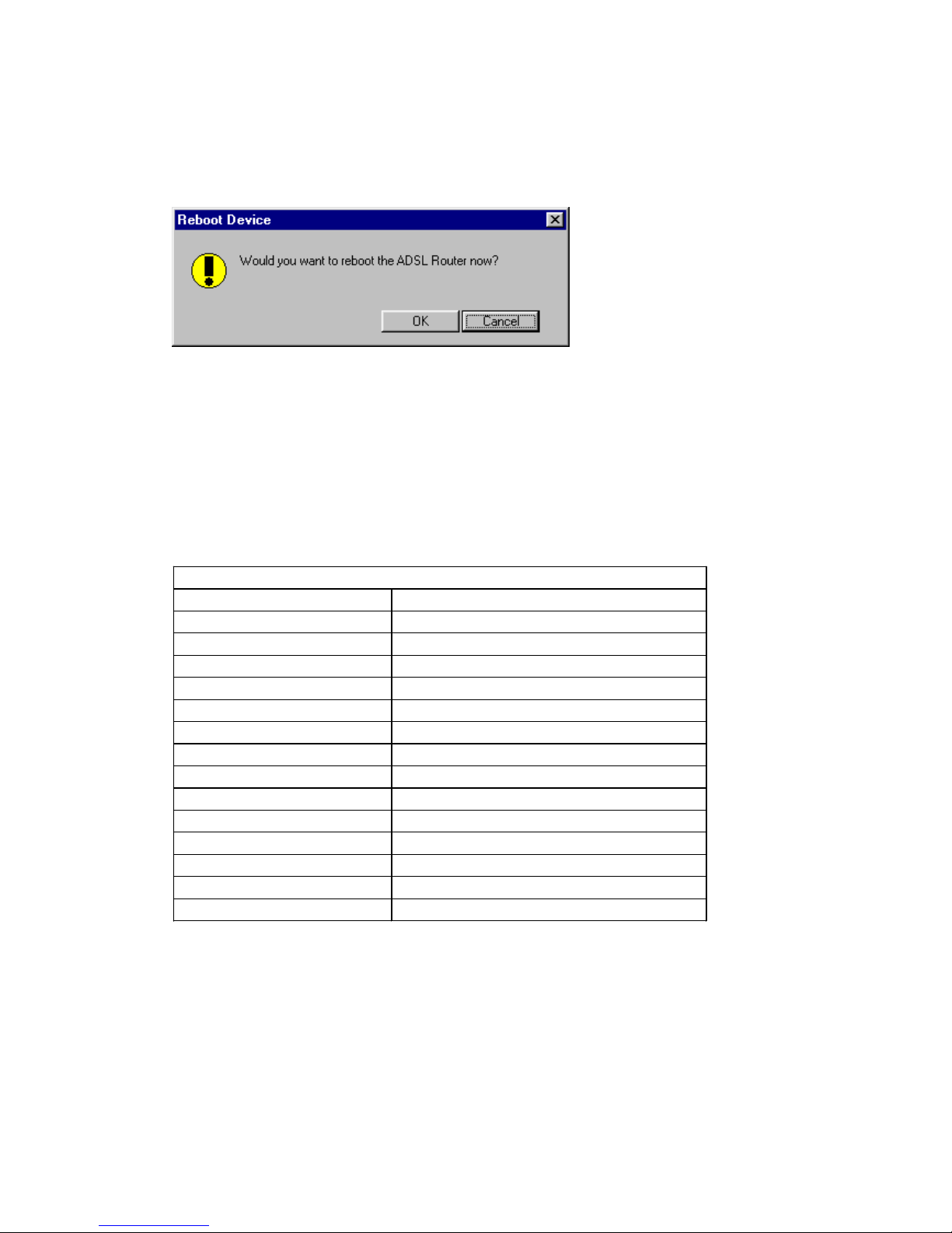
Some functions are not able to start to work after configuration. You
need to Save and Reboot the system to active those new settings.
Note: After you reboot system, you have to re-login the system again.
Information
Click this item to view the system information of the router. A sample
is listed below for reference.
Information
Model A400
System Version Version 2.1 06/18/2001
CPU MPC850DSL at 48 MHz
RAM 8MB
Flash 2MB
Chipset AD20msp930
Modem F/W Version 3110BE47
Server IP Address 127.0.0.1
MAC Address 00:01:E1:00:01:37
Hostname ATU-R
PPP Encryp t ion None
PPP Authentication PAP
System up time 0 day 1 hour 27 min 18 sec
Syn. up time 0 day 0 hour 0 min 0 sec
PPP up time 0 day 0 hour 0 min 0 sec
Page 54

52
Troubleshooting
Below are the potential problems you may run into and the possible
solutions. After each problem description, some instructions are provided
to help you to diagnose and to solve the problem.
Problem Action
None of the LEDs are on when
you turn on the router
Check the connection between the AC
adapter and the router.
If the error persists, you may have a
hardware problem. In this case you should
contact technical support.
Cannot access the router via
the console port
Check to see if the router in connected to
your computer’s serial port.
Cannot ping any station on the
LAN
Check the Ethernet LEDs on the front panel.
The LED should be on for a port that has a
station connected. If it is off, check the
cable between your router and the station.
Verify that the IP address and the subnet
mask are consistent between the router and
the workstations.
Initialization of PVC connection
failed
Ensure that the cable is connected properly
from the ADSL port to the wall jack. The
ADSL SYNC led on the front panel of the
router should be on.
Check that your VPI, VCI, type of
encapsulation and type of multiplexing
settings are the same as what you collected
from your telephone company and ISP.
Reboot the router. If you still have
problems, you may need to verify these
variables with the telephone company and/or
ISP.
 Loading...