

Olevia 232-S12 Service Manual
TITLE
Service Manu
LCD TV For 232-S12
Doc No.
Version 1.0
Page
1/44
Service Manual
LCD TV For 232-S12
Doc No.:
Version:1.0
Total Pages:41
Approval Made by
Hans Chung
2007/1/29
Kanzi Lee
2007/1/29
Revise by Revise by
Daniel Villa
12/8/06
Troubleshooting/disassembling
/Firmware Update/EDID
Update/Manual Structure
Randal J. Cook
12/7/06
Introduction
Doc No.
Version 1.0
Page 2/44
TITLE
Service Manual
LCD TV For 232-S12
Table of Contents
1. Introduction………………………………………………………………….......3
1-1 Preface……………………………….……… …… …. ……… …… ……… … ……………..3
1-2 Caution…………………………………………………..………………………………….3
1-3 Warning………………………………………………………..……………………………3
2. Specifications…………………………………..……………….…………………4
3. Wiring Diagram…………….……………………………………….…………….
4. Trouble shooting flow chart…………………………………………………….
4-1 Abnormal Display………………………………………………………………………....6
4-2 Abnormal Power On/Off…………………………………………………………………..7
4-3 LED Light Abnormal Display、Keypad Problem………………………………………..8
4-4 Image Abnormal Display………………………………………………………………….9
4-5 Audio Abnormal Output…………………………………………………………………..10
4-6 The Other Abnormal Display……………………………………………………………..11
5. Disassembly……………………………………………………………………12
5-1 Stand.……………………………………………………….……………………………….12
5-2 Back Cover……………………………………………………….…………………………1
5-3 System Board……………………………………………………………………………….1
5-4 Power Module………………………………………………………………………………14
5-5 Panel Module……………………………………………………………………………….15
5-6 Speaker..…………………………………………………………………………………..16
5-7 Keypad Board………………………………………………………………………………16
6. Firmware upgrade………………………………………………………………..17
7. EDID write in and ADC correction and Parameter Adjustment………………..20
7-1 EDID write in……………………………………………………………………………...20
7-1.1 EDID tools………………………………………………………………………………20
7-1.2 EDID write in……………………………………………………………………………20
7-2 ADC Correction and Parameter Adjustment………………………………………………21
7-2.1 ADC Correction…………………………………………………………………………21
7-2.2 Parameter Adjustment.……………………………………………………………………22
8. Exploded view…………………………………………………………………...23
9. Parts List and Photo……………………………………………………………...25
9-1 Parts List…………………………………………………………………………………...25
9-2 Parts Photo…………………………………..……………………………………………26
9-3 Parts List(Low bright panel)…………………………………………………………...33
9-4 Parts Photo(Low bright panel)……………..……………………………………………34
10. Block Diagram………………………………………………………………...41
5
6
2
3
Doc No.
Version 1.0
Page 3/44
TITLE
Service Manual
LCD TV For 232-S12
1. Introduction
1-1 Preface
This service manual describes module-level LCD TV repair for qualified service personnel.
This service manual also includes selected production troubleshooting information for
electronic technicians and engineers.
1-2 Caution
This service manual contains important safeguards and instructions that must be followed for
the safe and proper servicing of this TV.
1-3 Warning
1. Advise customers to follow all operating instructions and safety precautions that hav e been
furnished with the product.
2. Unplug the ac line cord before cleaning or disassembling the product.
3. Check the ac line cord and plug for wear or damage and replace as necessary.
4. Do not use liquid cleaners or aerosol cleaners to clean the display.
5. Do not place the product on an unstable table or cart. It can cause the product to fall,
resulting in injury and product damage. If a cart is used, use caution when moving the
cart/apparatus combination to avoid injury from tip-over.
6. Use only replacement parts specified by the manufacturer or replacement parts with the
same performance and safety characteristics. Use of substitute parts with different
characteristics can result in fire or electric shock.
7. Do not hit the LCD panel. In case of breakage, use care when removing broken glass.
8. Keep the product away from heat sources such as radiators, heaters, stoves, and other
heat-generating apparatus.
9. Do not block any ventilation openings.
10. Do not use the product near water; for example, near a bathtub, washbasin, kitchen sink
laundry tub, in a wet basement, or near a swimming pool.
11. If the product uses a grounded-type ac plug and line cord, but the location has a 2-prong
receptacle, advice the customer to contact a qualified electrician to replace the outlet.

TITLE
Service Manual
LCD TV For 232-S12
2. Specifications
PRODUCT SPECIFICATIONS
LCD Panel
Power Management
(Standby Mode)
Displayable Resolution
Pixel Pitch
LCD Display Color
Viewing Angle
32" TFT
< 1W
VGA 1360*768 max.
0.17025mm x 0.51075mm x RGB
16.7M colors(8-bits colors).
178(H)/178(V) (CR>10)
Doc No.
Version 1.0
Page 4/44
Response Time
Active Display Area
RF Tuner
Power
Speaker
Compliance
Temperature
Weight w/o stand
Weight w/ stand
Gross Weight
Dimensions (WxDxH)
8ms (Gray to Gray)
697.685mm x 392.256mm (31.51" diagonal)
Combo RF (NTSC/ATSC)
Voltage : 100~240 V
Consumption : 164W
10W
FCC, cUL, CSA, Energy Star
Operating: -10℃~40℃
Storage: -10℃~60℃
33.63lbs
35.5lbs
45.421lbs
37.76 inches x 9.37 inches x 22.20 inches
Carton Dimensions
(WxDxH)
42.80 inches x 12.40 inches x 25.35 inches
TITLE
Service Manual
LCD TV For 232-S12
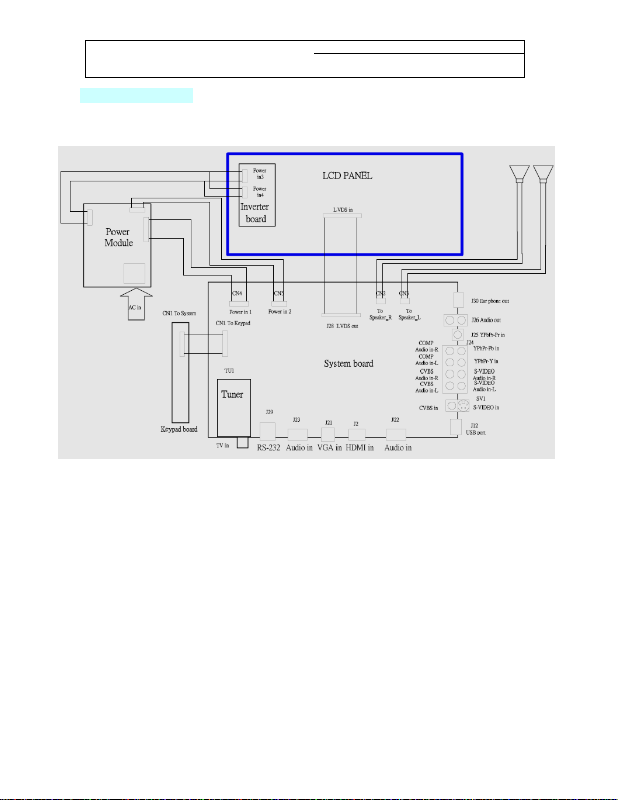
3. Wiring Diagram
Doc No.
Version 1.0
Page 5/44
Doc No.
m
Version 1.0
Page 6/44
TITLE
Service Manual
LCD TV For 232-S12
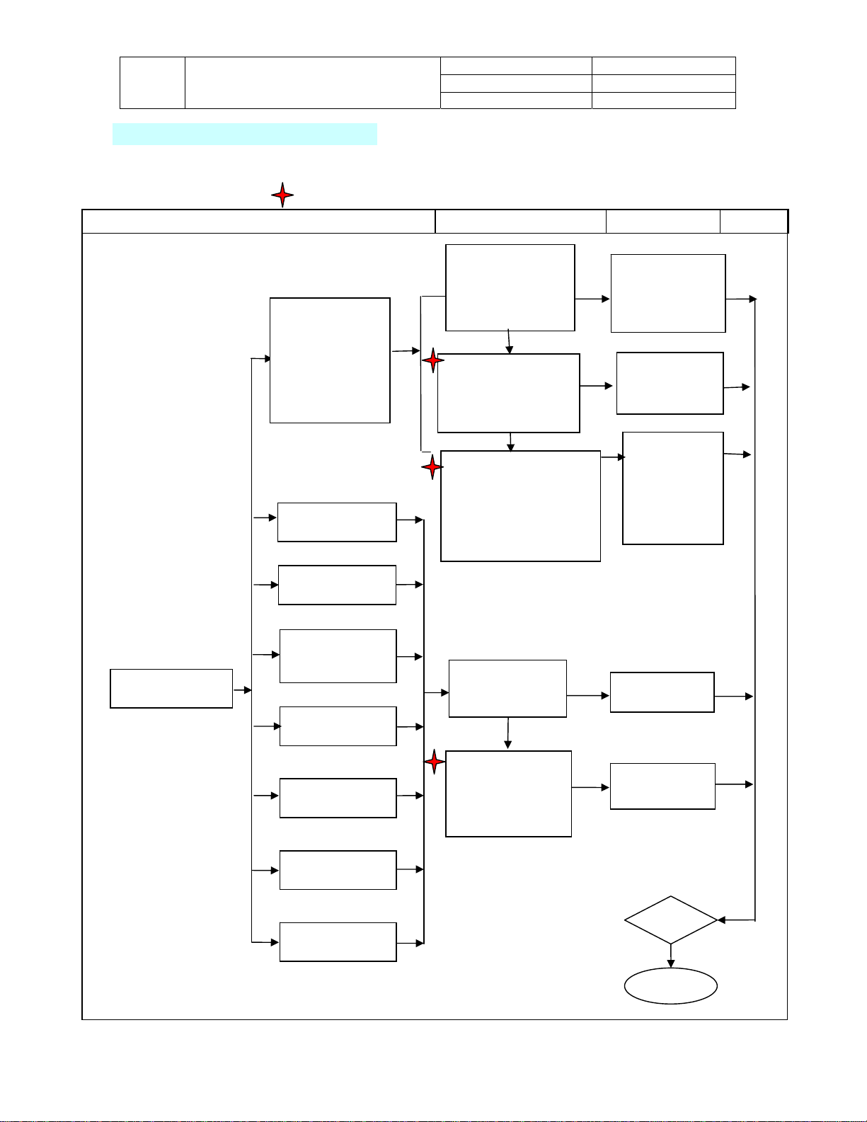
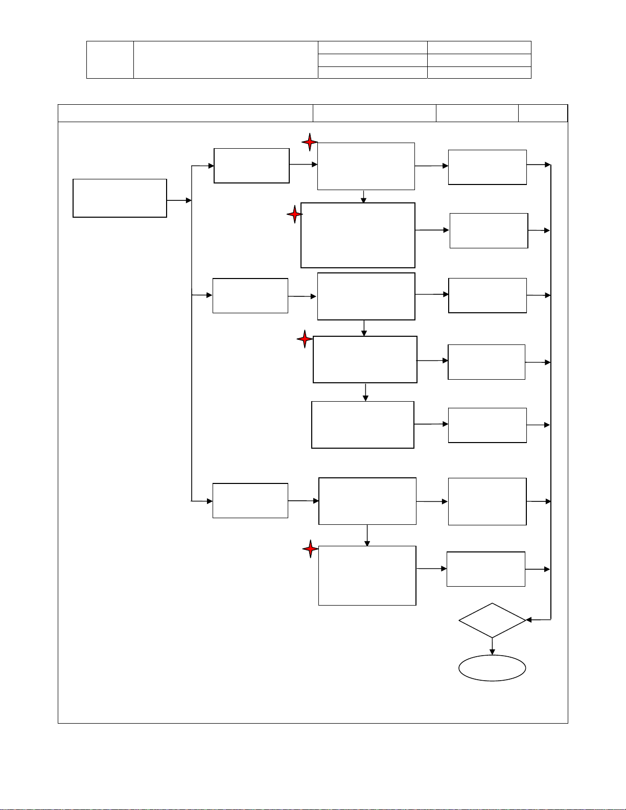
4. Trouble shooting flow chart
4-1 Display Problems
Note: Refer to the Wiring Diagram during troubleshooting for a visual of inter-connections
when indicated by this symbol.
Display Problems
Trouble Condition Check Item Replace Material Test
Abnormal display
1. No video Image
2. Video noise
3. Display flashes
4. Abnomal color
Bright spots
Dark spots
Backlight uniformity
Light leakage
Spot & Simi
Ghosting
Dust & Scratch
Step1:
1. Check for a loose video
cable connection
2. Check video cable
3. Check source settings
4. Check TV input
OK
Step2:
Check for a loose or broken
connection between Con.J28
from system board to Panel
LVDS connection.
OK
Step3:
1. Check System board (5Vs)
CN4-pin1 to ground = 5V,
2. Check System Board
CN4-pin3 to ground = 5V
CN5-pin2 to ground = 12V
Step1:
Check damage to
panel
OK
Step2:
Check for a loose or
broken connection
between Con.J28 from
system board to Panel
LVDS connection .
1. Reconnect cable
2. Replace cable
Fail
3. Change source
settings
4. Change TV input
5. Run auto Scan
Secure connection
Fail
or replace the
LVDS wire
Fail
1.Replace Power
Module if voltage
is missing.
2.Replace Syste
board if voltage is
missing.
Fail
Fai
Replace Panel
l
Replace LVDS
connect wire
Test
Finish

TITLE
Service Manual
LCD TV For 232-S12
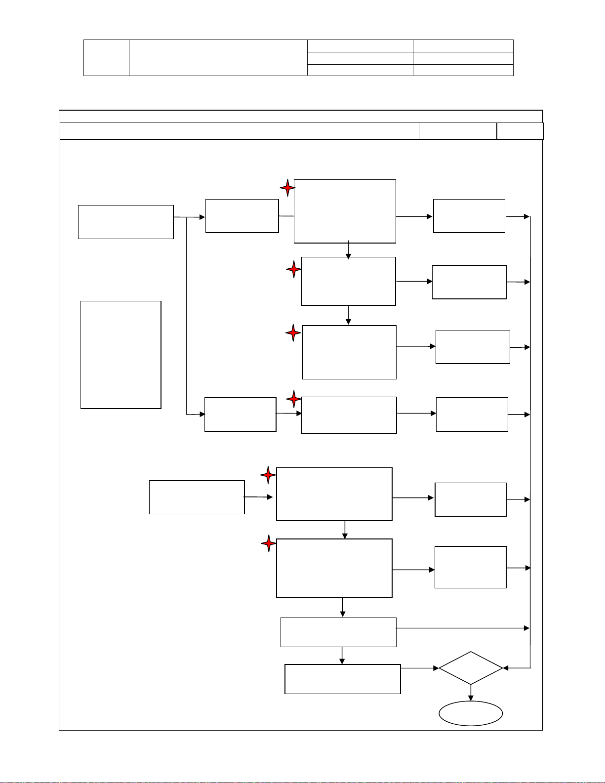
4-2 Abnormal Power On/Off
Trouble Condition Check Item Replace Material Test
Abnormal Power
On/Off
No Power
Note: Before
proceeding confirm
that Power cable is
connected and that
proper voltage is
being fed to TV.
(Check power
switch located next
to power input and
confirm that it’s
ON.)
Abnormal Power
Off
Shut down
Source can’t
switch
Doc No.
Version 1.0
Page 7/44
Step1:
Check Power Supply, Con.
CN904–pin 7 to ground = 5VS
Con .CN904 pin 8 to ground =
5V
OK
Step2:
Check Keypad board
CN1-pin1 to ground = 5V
or Check D1 lighting?
OK
Step3:
Check System Board
CN4 pin1 to ground = 5Vs,
and pin3 to ground = 5V,
Fail
Fail
Fail
Replace Power
supply
Replace Keypad
board
Replace System
board
Test
Finish
TITLE
Service Manual
LCD TV For 232-S12
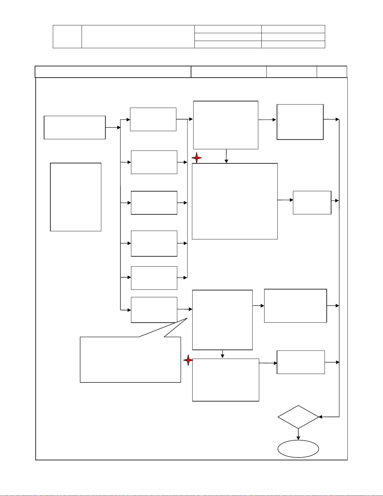
4-3 LED is Malfunctioning、Keypad Problem
Trouble Condition Check Item Replace Material Test
LED is Malfunctioning
LED is not working
Step1:
Check CN 1 on system
board to CN 1 on Keypad
connection or bad cable
Step2:
Note: Before
proceeding confirm
that Power cable is
connected and that
proper voltage is
being fed to TV.
(Check power
switch located next
to power input and
confirm that it’s
ON.)
LED flashes
Check Power supply Con.
CN904-pin7 to ground =5V
Keypad doesn’t work
Step1:
Check connector CN 1 on
System board to CN1 located
on Keypad board for a loose
Step2:
Check connector CN 1 on
System board to CN1 located
on Keypad board for a broken
Step 3:
Replace Keypad Board
Step 4:
Replace System Board
Doc No.
Version 1.0
Page 8/44
board for a loose
OK
Check Keypad board
D1 & CN1-pin 1 to
ground = 5V
OK
Step3:
Check System board
CN1-pin1 to ground =
5V
connection
OK
cable
OK
Fail
Fail
Fail
Fail
Fail
Fail
Fail
Secure connection or
replace cable
Replace board if
there is no voltage
Replace System
board if there is no
voltage
Replace Power
Supply if there is no
voltage
Secure connection
Replace Cable
Test
Finish
TITLE
LCD TV For 232-S12
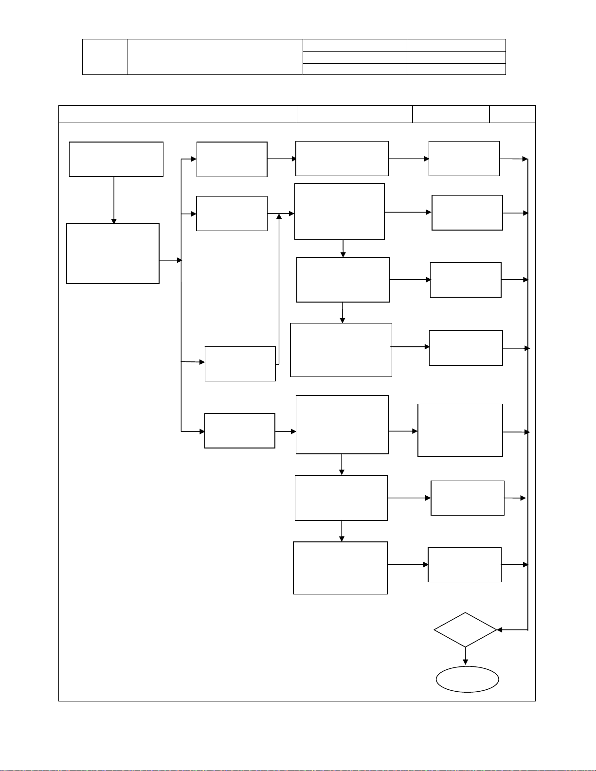
4-4 Image Problems
Trouble Condition Check Item Replace Material Test
Image Problems
Note: Before
proceeding confirm
that Power cable is
connected and that
proper voltage is
being fed to TV.
(Check power
switch located next
to power input and
confirm that it’s
ON.)
Note: Before proceeding make
sure the PC is not in standby or
hibernation mode. Make sure
the video card is secure and not
loose (AGP or PCI slot).
Service Manual
No picture through
component
No picture through
composite
No picture through
S-Video
No Picture through
Tuner
No picture through
HDMI
No picture through
VGA
Doc No.
Version 1.0
Page 9/44
Step1:
1. Check video cable
connection
2. Check video cable
3. Check source settings
OK
Step2:
1. Check System Board component
L29, L30,L31 for a short.
2. Check System Board component
FB10,L20 for a short
3. Check System Board component
FB11, FB12, L16, L17 for a short
4. Check System Board component
L23 ,FB53, FB54 for a short
5. Check J2 Con. broken? E5
EDID OK?
Step1:
1. Check if VGA cable
is loose.
2. Make sure the PC is
set to a resolution the
TV supports
3. Check both ends of
VGA cable for broken
or loose pins.
OK
Step2:
Check component J21 on
system board for a short &
component E6 that stores
EDID information for a
short.
Fail
1. Secure connection
Fail
2. Change PC resolution to
fit the timing table
3. Replace VGA cable
Fail
1. Reconnect cable
2. Replace cable
3. Change source
settings
Fail
Replace System
board
Replace System
board
Test
Finish
TITLE
4-5 Audio Problems
Trouble Condition Check Item Replace Material Test
Audio Problems
Make sure external audio
connection is secure before
proceeding with
troubleshooting
Service Manual
LCD TV For 232-S12
Can’t adjustment
Volume
No audio
No audio on one
side of speaker
No audio through
earphone
Doc No.
Version 1.0
Page 10/44
Check switches on the
keypad board
Step1:
Check for loose
connection between
CN2 and peaker and
CN3 and speaker
OK
Step2:
Check if the Speaker
module is broken
OK
Step3:
Check System board
CN5-pin1 to ground =
12V
Step1:
1. Check earphone
connection
2. Check earphone
cable
OK
Step2:
Check OSD speaker
setting is off and not on
OK
Step3:
Check System board
component J30 & Q28
for a short
Fail
Replace Keypad
Fail
Fail
Fail
Fail
Fail
Fail
Replace connect
Replace speaker
Replace Power
1. Secure earphone
connection.
2. Replace Earphone
cable
Replace System
board
board
wire
module
Module
Set the speaker
setting to off
Test
Finish
TITLE
LCD TV For 232-S12
4-6 Other Problems
Trouble Condition Check Item Replace Material Test
Other display problems
Service Manual
Sometimes picture
flashes
Remote control fails
Firmware update
fails
Doc No.
Version 1.0
Page 11/44
Step1:
Check Con. J11 to
panel LVDS onnection
OK
Step2:
Check System board
component Q13, Q7
FB19(LPL),
FB20(CMO&AUO) for a
short
Step1:
Check Remote control
& Battery
OK
Check connectorCN 1
on System board to CN1
located on Keypad board
for a loose connection
OK
Step3:
Check for a broken
Keypad/IR board
Step1:
1. Check USB Disk
is FAT32 format
OK
Step2:
Check System board,
J12 Connector and
FB69, E15 for a short
NO
Fail
Fail
Fail
Fail
Replace connect wire
Fail
Fail
Fail
Replace Keypad/IR
1.Change USB Disk
format to FAT32
2.Copy FW file to
USB Disk
Replace LVDS
connect wire
Replace System
board
Replace Remote
control & Battery
board
Replace System
board
Test
Finish
TITLE
LCD TV For 232-S12
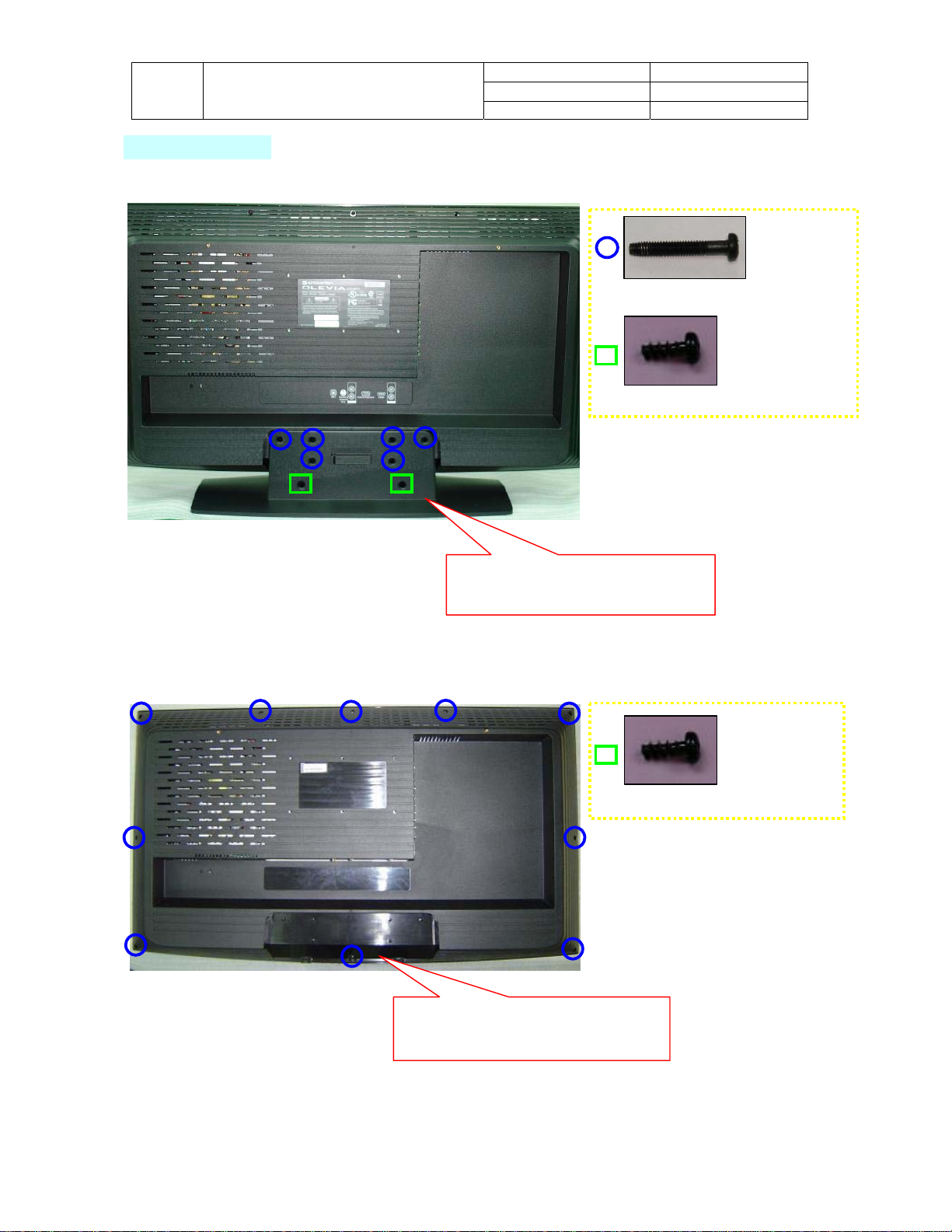
5. Disassembly
5-1 Stand
5-2 Back Cover
Service Manual
Doc No.
Version 1.0
Page 12/44
Screw M4 25mm
ScrewT4*10-PH-Cross-Black
1. Loosen and remove 8 screws.
2. Safely remove the Stand.
ScrewT4*10-PH-Cross-Black
1. Loosen and remove 10 screws.
2. Safely remove the Back Cover.
TITLE
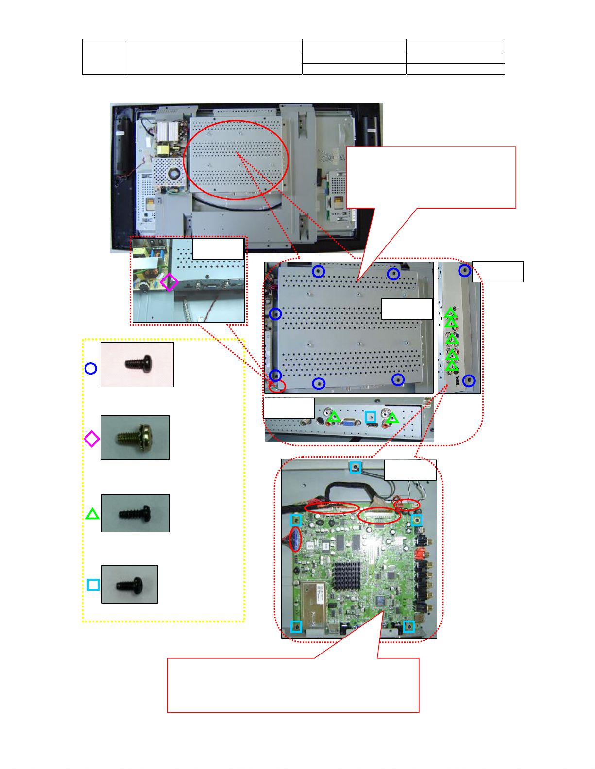
5-3 System Board
Service Manual
LCD TV For 232-S12
Doc No.
Version 1.0
Page 13/44
1. Loosen and remove 17 screws
as indicated in Figure 1~4.
2. Take off the Support Metal.
Screw MT4x8-PH-Cross-Black
Screw M4x8-PH-CETW-NI
Figure 4
Figure 3
Figure 2
Figure 1
Figure 5
Screw T3*8 Black
MT3*6-PH-CROSS-Black
3. Loosen and remove 5 screws and safely remove
connectors as indicated by red circles on Figure 5.
4. Take off the System Board.
TITLE
Service Manual
LCD TV For 232-S12
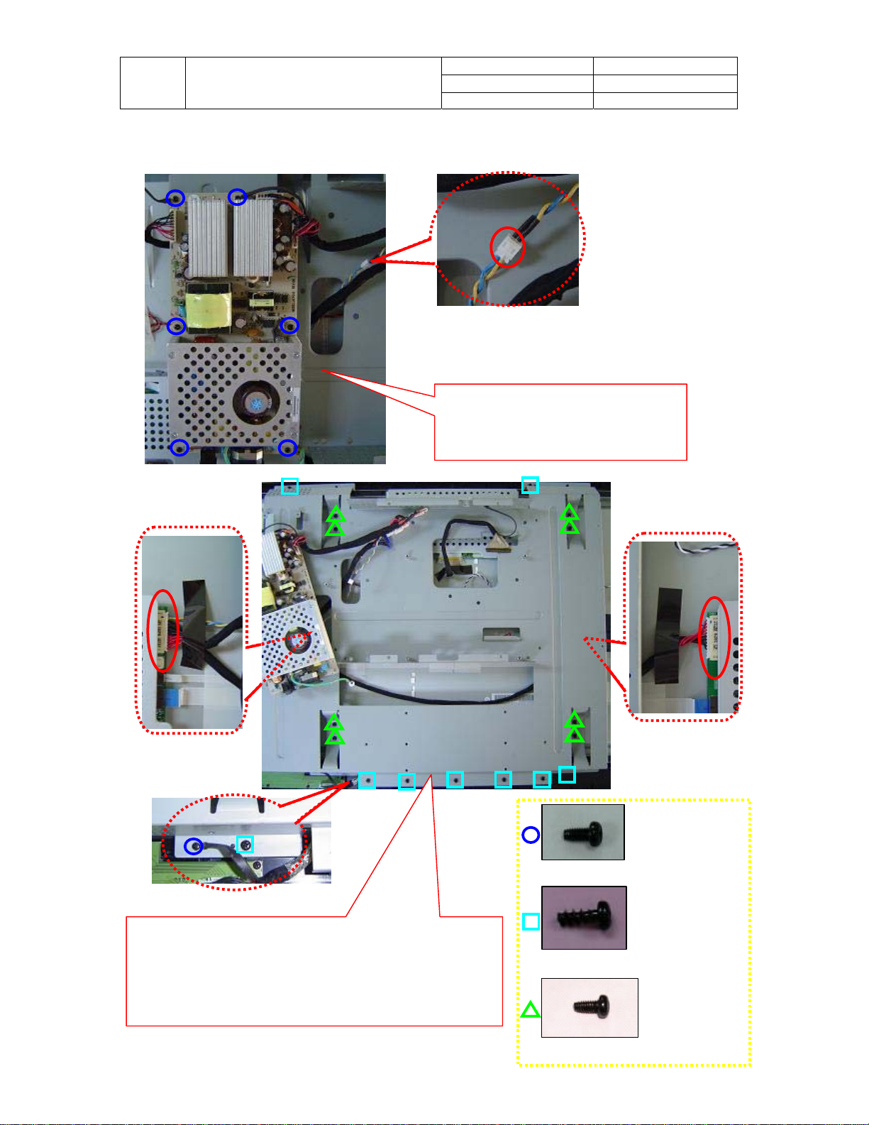
5-4 Power Module
2. Loosen and remove 18 screws and safely remove
connectors indicated by red circles.
3. Move the Wall mount and pull out connector as red
circles.
4. Safely remove the Power module and Wall mount.
Doc No.
Version 1.0
Page 14/44
1. Loosen and remove 6 screws
and safely remove connectors
indicated by red circles.
MT3*6-PH-CROSS-Black
ScrewT4*10-PH-Cross-Black
Screw MT4x8-PH-Cross-Black
 Loading...