

O.L.E. (UK) T4020, T5020 Installation Manual

O.L.E. (UK) Ltd
T4020 \ T5020 \ INSTRUCTION & INSTALLATION
MANUAL
Revision: 02
Date: 26/03/2017
PD02/0002

Page 1 of 22
Contents
Introduction .......................................................................................................................................... 2
Safety Warnings ................................................................................................................................ 2
Contact Information.......................................................................................................................... 2
Principle of Operation ........................................................................................................................... 2
Installation Instructions ........................................................................................................................ 3
Mounting Holes ................................................................................................................................ 3
Input Connections ............................................................................................................................. 4
Output Connections .......................................................................................................................... 4
Power Input / Output Connections ................................................................................................... 5
Tank Level Probes ............................................................................................................................. 5
Gauge Configuration ......................................................................................................................... 6
Operational Instructions ................................................................................................................. 12
Appendix 1 (T5020 Wiring Diagram) ................................................................................................... 13
Appendix 2 (Modbus Register Table) .................................................................................................. 14
Appendix 3 (Accessories) .................................................................................................................... 18
B8 – Bund Probe / Level Switch ...................................................................................................... 18
B2 – Water Sensor .......................................................................................................................... 18
B2-T – Water and Temperature Sensor .......................................................................................... 18
TP – Temperature Sensor................................................................................................................ 19
R5 – Relay Module .......................................................................................................................... 19
USB Programmer and Configuration Software ............................................................................... 20
F. A. Q’s / Troubleshooting ................................................................................................................. 21

Page 2 of 22
Introduction
The Purpose of this document is to outline the installation and operational procedures of the
T4020 \ T5020.
Safety Warnings
To avoid injury please read this manual carefully before installation. Failure to do so could result in injury or
failure of the equipment, this will invalidate any warranties given.
CAUTION
The installation and assembly of this product may only be performed by a skilled electrician.
WARNING
This product contains 240V AC and 24V DC, Isolate power to the unit before removing the cover.
Contact Information
Principle of Operation
Digital Tank Gauge. Accuracy +/- 0.25%.
This gauge is fitted in a weatherproof rated IP65 enclosure, for outdoor use. Fitted with a backlight that
enables easy reading (Backlight turns off after 1 hour). Litres and % Bar are displayed.
M (Master) and up to 3 other trigger points can be displayed.
The gauge can be setup for almost any tank shape, such as Cuboid, Rectangular, Cylindrical, Cylindrical with
dished ends, bespoke based on strapping table. (Level in meters and volume in cubic meters).
Can read temperature as an option, temperature probe required. “TP” probes read 0°C to 70°C.
OLE (UK) Ltd,
Barns A & B,
Bowely Farm,
Bowely Lane,
South Mundham,
Chichester,
West Sussex,
United Kingdom
PO20 1NB
+44 (0)1243 267930
sales@oleuk.com

Page 3 of 22
Installation Instructions
Mounting Holes
There are 4 mounting holes in the base of the unit (indicated with the Blue Circles).
These are located behind the front panel screws.
The distance between mounting holes is 110mm wide X 160mm high.
Page 4 of 22
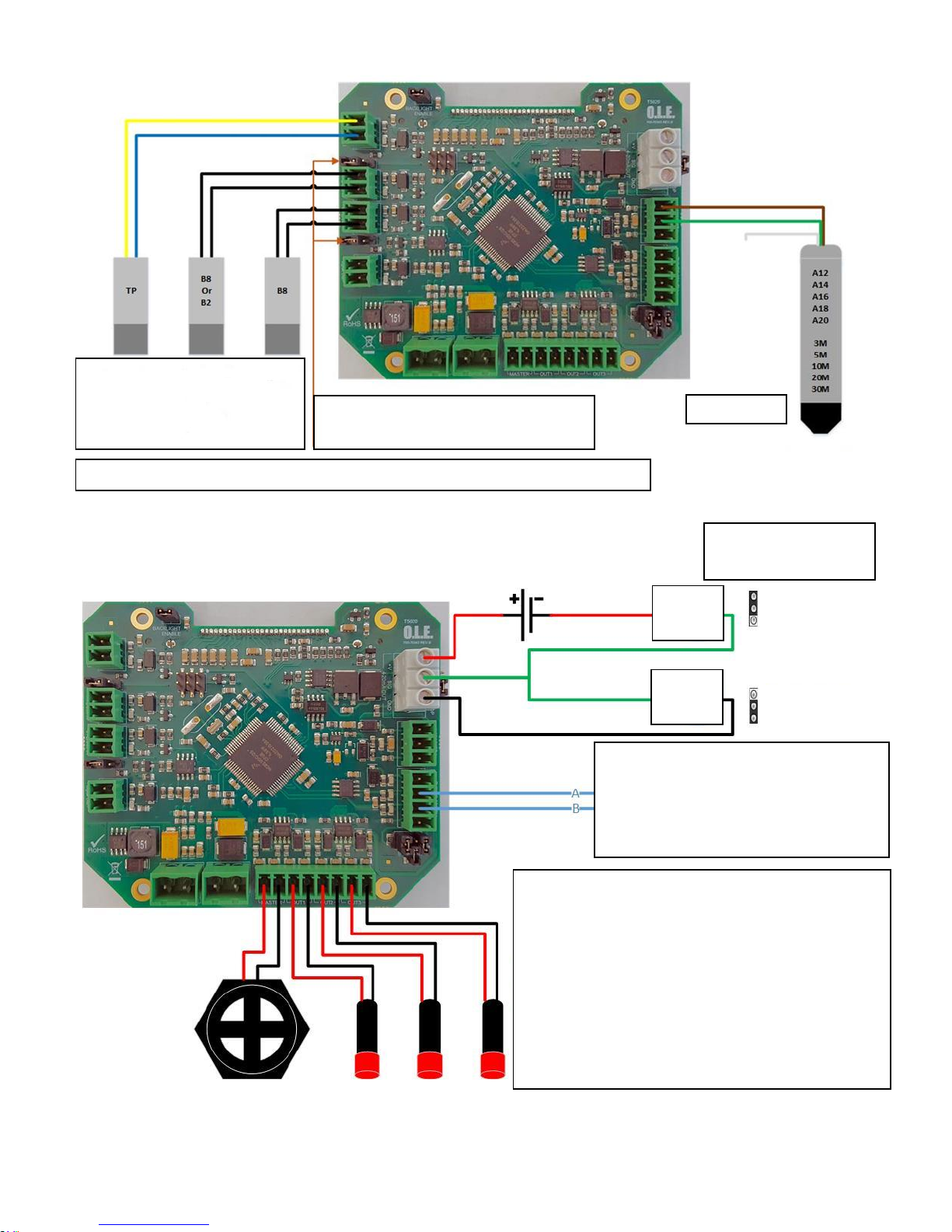
Input Connections
Output Connections
RS485 / MODBUS RTU
or
USB Programmer
A = Orange (Old Programmer = Yellow)
B = Yellow (Old Programmer = Blue)
Level Probe
Note: Jumper needs to be on Enable
for High Level and / or Bund Alarm
TP = Temperature Probe
B8 or B2 = High Level probe or
water bottom sensor
B8 = Bund Probe
Configurable Alarm Outputs
All are Switchable Supply Voltage.
M = Master Alarm, set 95% Rising and can be
acknowledged from the front panel.
B = (Bund or Water Bottom) Alarm also acknowledged
from the front panel
1,2,3 are additional Alarms.
1 = 90% Rising, 2 = 10% Falling, 3 = 5% Falling.
These are factory set on request or with the
Configuration Kit / lead by the end user.
Passive
mA
Loop
mA
OUTPUT – Analogue 4-20mA
Passive – Externally Powered
Loop – Powered by T5020
Reed switch used in B8 and B2 probes: Rating 10w / Switching Voltage 0.5A 240VAC

Page 5 of 22
Power Input / Output Connections
WARNING
Before applying the power, DOUBLE CHECK all the connections to the inputs and outputs.
Tank Level Probes
Standard Probes Legacy Probes
Standard Probes
Legacy Probes
A12 / 3m = 3m Sensor with 10m of cable
A / B29 = 1.0m Sensor with 4m of cable
A14 / 5m = 5m Sensor with 10m cable
A / B30 = 1.5m Sensor with 4m of cable
A16 / 10m = 10m Sensor with 10m cable
A / B23 = 3.0m Sensor with 6m of cable
A18 / 20m = 20m Sensor with 20m cable
A / B25 = 5.0m Sensor with 7m of cable
A20 / 30m = 30m sensor with 30m cable
A / B26 = 7.0m Sensor with 10m of cable
A / B27 = 10.0m Sensor with 12m of cable
Standard Probes – Wire Colours
Legacy Probes – Wire Colours
Brown
+V
Red
+V
Green
Signal
Black
Signal
White
Not Used
Blue
Temperature +
Yellow
Temperature -
Legacy A Series Probes Do Not Have Temperature
100 – 240v AC
Maximum
Current - 0.7A
Power Pass
through from
Power Supply
Page 6 of 22
Gauge Configuration
The set-Up of the Tank Gauge system using Interface lead and he software on a PC / Laptop.
Latest version of the software is V1.0.0.16
Tank Gauge adjustments can be made with the T4020 Configuration software.
This needs to be loaded on to Service Laptop or an Office PC.
1st Issue that will nearly always catch you out. If the gauges are set in ‘Modbus’ mode, or if they are in
Standard. To talk to the gauge with the configurator software, the gauge needs to be in Standard mode.
If it is not, disconnect the power lead (24vdc supply), and hold down the front middle alarm button (for 3
seconds) and reconnect power. (Front display will change to ‘Standard’. (Cycle power again when finished.)
2nd Issue, the comms lead will not talk to the tank gauge. “USB Serial Com Port”
This is the port you require to set the configurator, this is achieved by following the instructions for the Device
Manager below. This shows Windows 10, but if you have a different version of windows as long, as you can
access the device manager and find the com port number there shouldn’t be an issue.
IF YOU HAVE ANY ISSUES WITH SETTING UP / ACCESSING THE DEVICE MANAGER
PLEASE REFER TO DOCUMENT PD02/0003 – DEVICE MANAGER CONFIGURATION.
This is available from the OLE website as a downloadable .pdf
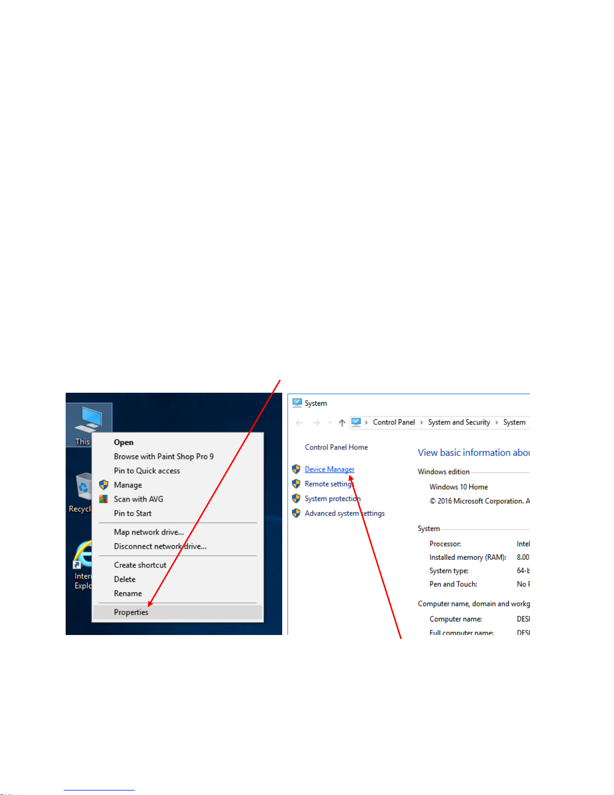
Windows Setup (Windows 10) / Device Manager.
Left click on the This PC icon. Scroll down and click on the Properties tab.
This will open the Control Panel / System and Security / System page. Click on the Device Manager Icon.
This will bring up the device manager page.
 Loading...