

Ole Hickory Pits SSG, ELEC, EL-ED, EL-ED/X, ELIB Owner's Manual
...

Warranty
Procedure IMPORTANT
Please Read
Should there be a mechanical problem with your warrantied unit(s) Monday through Friday, follow
the procedure below.
1. Call our Service Manager, Kevin Kessel, at 1-800-223-9667 between the hours of 8:00
am - 5:00 pm, Monday thru Friday CST. Give Kevin your Model and Serial Number of
your unit.
2. Explain the problem. Most often the problem can be handled by the Service Manager.
If the problem requires a service company, OHP Service Manager will contact the
service company, ascertain the work needed, issue an authorization number to the
service company and contact you with date, time and service work that has been preapproved.
3. After pre-assigned service has been completed, call the OHP Service Manager to make
sure defective parts are returned and all work has been completed.
Should there be a mechanical problem with your warrantied unit(s) during the weekend or any
holidays that OLE HICKORY PITS home office is not opened, follow the procedure below.
1. Call our office at 1-800-223-9667 and leave message containing Name, Address, Business
Name, Model, Serial # and mechanical problem. Also leave the name and phone number
of the pre-approved service company you will be using.
2. Contact your pre-approved service company.
3. Contact OLE HICKORY PITS, during the next regular business day that the required work
has been completed and defective parts have been returned.
Failure to follow the above may result in warranty claim being denied.
* Also read and follow the LIMITED WARRANTY Page in this manual.
REV110928

Do not store or use gasoline or other flammable vapors or liquids in the vicinity of this or any other
appliances.
OLE HICKORY PITS
333 North Main Street
Cape Girardeau, MO 63701
Owner’s Manual for Model SSG
Installation & Operating Instructions
Notice: These instructions should be affixed to the unit or adjacent to your Ole Hickory Pit
Please retain this manual for future reference
Notice: Installation must conform with local codes, or in the absence of local codes, with the
National Fuel Gas Code, ANSI Z223.1-1992, including
1) The unit and its individual shutoff valve must be disconnected from the gas supply
piping system during any pressure testing of that system at test pressures in excess of
one half psig.
2) The unit must be isolated from the gas supply piping system by closing its individual
manual shutoff valve during any pressure testing of the gas supply piping system at
test pressures equal to or less than one half psig.
Notice: This unit must be electrically grounded in accordance with local codes, or in the
absence of local codes, with the National Electrical Code, ANSI/NFPA 70-1990.
FOR YOUR SAFETY
Keep the unit free of combustible material. Allow 18" clear space around access panels.
If you smell gas: 1) Open Windows
2) Don’t Touch Electrical Switches
3) Extinguish Any Open Flame
4) Immediately Call Your Gas Supplier
Electrical Instructions: This appliance is equipped with a three-prong (grounding) plug for your
protection against shock hazard and should be plugged directly into a properly grounded three-prong
receptacle. DO NOT CUT OR REMOVE THE GROUNDING PRONG FROM THIS PLUG.
Warning - Exterior Surfaces May Be Hot
WARNING: This unit must be properly vented and used in an area where there is sufficient
dilution air to prevent concentration of CO from occurring.
Do Not Obstruct The Flow of Combustion and Ventilation Air Around Unit
Allow Adequate Clearances For Servicing and Proper Operation

WARNING; Improper installation, adjustment, alteration, service or maintenance can
cause property damage, injury or death. Read the installation, operating and maintenance
instructions thoroughly before installing or servicing this equipment.
Model SSG
Please Read All Instructions Thoroughly
Installation Instructions:
These instructions were prepared for the guidance of those installing this particular
gas and wood burning barbecue pit. While they apply in principle to most installations, they
should not be interpreted as meaning the only safe and economical way to install the unit. It
may be necessary to deviate from these instructions in some instances in order to comply
with local codes in effect in your area. We recommend the installer confer with the proper
local municipal officials regarding any specific code regulations. Installation should be
performed by a qualified installer.
VISUALLY INSPECT THE INSTALLATION LOCATION: An Ole Hickory Pit shall not be
installed in any location where facilities for normal air circulation or infiltration are so
limited so as to interfere with ready obtainment of all air necessary for proper ventilation
and draw.
Ole Hickory Pits must be secured for stationary installation on a level; impervious
floor (concrete or comparable). Floor has to support 2100 to 2600 pounds at all times. The
unit is suitable for installation on a combustible floor.
‘NOTICE; If your Ole Hickory Pit is to be installed with casters, it must be installed
with the casters supplied, a connector complying with either ANSI Z21.69 or CAN/CGA-6.16
and a quick-disconnect device complying with either ANSI Z21.41 or CAN1-6.9. It must also
be installed with restraining means to guard against transmission of strain to the connector,
as specified in the appliance manufacturer’s instructions.” Adequate means has been
provided to limit the movement of the unit without depending on the connector and the
quick disconnect device or its associated piping to limit oven movement. PLEASE LOCK
CASTERS ONCE UNIT IS IN PLACE.
A manual shutoff valve MUST be supplied in the gas line between the unit and the
meter in an easily accessible location. A regulator is required to maintain correct gas
pressure to burner. Please include a drip leg or sediment trap in the gas supply line.
INSPECTION AND PREPARATION OF UNIT. Visually inspect the Ole Hickory Pit by
removing the service access panels and ensure that motors and burner have not been
loosened during shipment of unit. Replace the service panels after inspection. The racks in
the cooking chamber should be properly set in position.
Before proceeding with installation, read all instructions carefully and make sure all
switches are set to the “OFF” position.

SAFETY TIPS
Please Read & Follow All Safety Instructions!
1. The area surrounding the Ole Hickory Pit MUST be kept clear of combustible materials. DO NOT
STORE OR USE GASOLINE OR OTHER FLAMMABLE VAPORS OR LIQUIDS IN THE VICINITY OF THIS
OR ANY OTHER APPLIANCE.
2. Ventilating air MUST NOT be obstructed from reaching the pit. Adequate makeup air and
ventilation are required to keep motors cool and allow proper operation of the burner.
3. At time of installation, the unit must be electrically grounded in accordance with local codes. In
the absence of local codes, please refer to the National Electrical Code, ANSI/NFPA 70-1996.
4. The service access panels should be properly installed and maintained in place during operation
of the unit. Should servicing be required, make sure the gas supply to the unit is turned off and
that the unit is unplugged before removing service panels.
5. NO ADJUSTMENTS TO THE POWER BURNER SHOULD BE MADE BY USER. If the burner does not
appear to be operating properly, turn gas supply off and contact Ole Hickory Pits or a qualified
serviceman for repairs.
6. Service work performed by unqualified personnel may void the warranty. Please do not allow
adjustments to be made to the unit that would alter the operation or disable the built in safety
features. Such alterations may result in a hazardous condition.
7. Flues are required on ALL Ole Hickory Pits. Failure to do so will result in unit malfunction and
substandard performance. (See the Gas Piping and Venting Instructions page)
8. This unit is suitable for installation on combustible floors.
9. Failure to follow recommended cleaning and maintenance procedures might also result in
hazardous conditions and void equipment warranty.
10. Please note on Fire Box: “Warning-Hot Surface Do Not Touch”
11. Please instruct all persons using this equipment on the proper use and maintenance.
12. Please maintain a minimum safety clearance from surrounding materials as follows:
Combustible Construction Noncombustible construction
Back: * 2" 2"
Right Side: * 18" 18"
Left Side: 18" 18"
Top: 2” 2”
Bottom: 6” 6”
*Indicates clearance needed for servicing and maintenance of smoker.
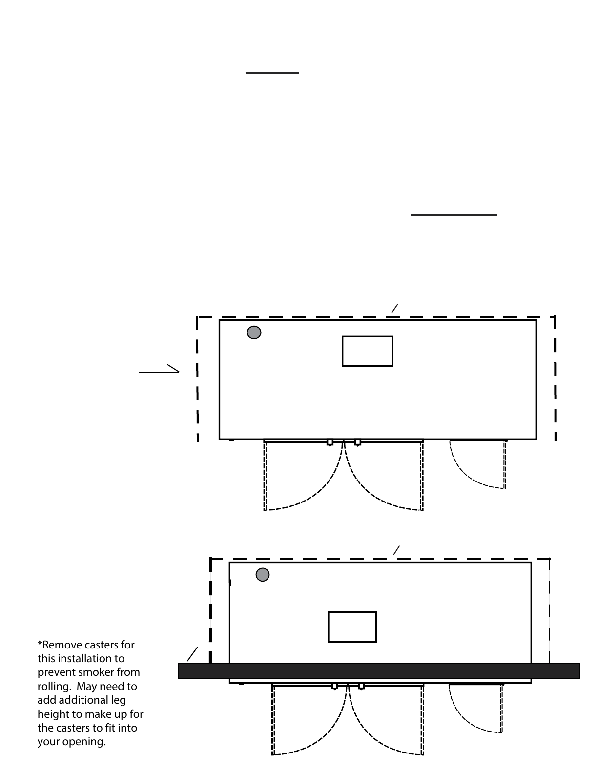
Models SSM, SSG, SSL & SSE Top View
Showing Clearance, Page 3 of Owners Manual, Titled Safety Tips:
#12. Please maintain a MINIMUM safety or mechanical clearance
from surrounding materials as follows:
Combustible Construction: Back 2"
Right S
Left S
Noncombustible Construction: Back: 2"
Right S
Left S
Any Installation that does not allow for the proper MINIMUM
Safety or Mechanical Clearance, as per ETL, may be considered a
Non-Approved Installation by Ole Hickory Pits. A Non-Approved
ide: 18"
ide: 18"
ide: 18"
ide: 18"
Installation ma
Example 1:
Free Standing
Inside or Outside
Bu
liding.
y void your warranty.
18"
2"
Smoke Evac.
Opening
18"
2"
Example 2:
Faced Thru Wall
Installation
*Remove casters for
this installation to
prevent smoker from
rolling. May need to
add additional leg
height to make up for
the casters to fit into
your opening.
Outside
Wall
18"
18"
Smoke Evac.
Opening

Operating Instructions
1. Preheat the Ole Hickory Pit to desired temperature by turning on all switches found on
the control panel. Recommended cooking temperature is 225 degrees F. and CANNOT
exceed 350 degrees F.
WARNING: Unit is equipped with an upper limit switch
that will shut down all operations until the
reset button, located under the service panel,
is manually reset.
Disconnect Power Before Removing Panel.
2. During the heating process, prepare the product to be cooked.
3. Begin loading the unit on the bottom racks first and evenly distribute the weight of the
product on all racks. DO NOT allow any of the product to hang over the front or back
edges or the racks. This may cause racks to tip and jam the rotisserie. If the product is
too large for the bottom rack, remove the top rack and load the product on the bottom
rack.
4. To advance the racks with the cooking chamber doors open, depress the Rotisserie Foot
Advance until the racks are advanced to the next position.
5. After, loading, allow the rotisserie to complete two revolutions to check for adequate
clearance of the product to the walls of the cooking chamber and racks. Reposition
product if necessary.
6. Wood used should be 4" to 10" in diameter and 16" to 24" in length. DO NOT ALLOW
ASHES OR LOGS TO OBSTRUCT THE BURNER TUBE OPENING. It is recommended to use
no more than 2 or 3 sticks of wood for a complete cooking cycle. Excessive amounts of
wood usage will overheat the cooking chamber and may trip the Upper Limit Switch.
7. When checking the meat, upon opening of the cooking chamber doors, the burner, and
convection systems are disabled. When the doors are closed, all systems are reactivated.
8. IN CASE OF POWER FAILURE: Turn off gas supply to unit. To prevent product spoilage if
cooking, the inside temperature of the unit can be maintained by manually keeping wood
in the firebox.
9. Contact factory, the factory representative or a local service company to perform
maintenance and repairs.
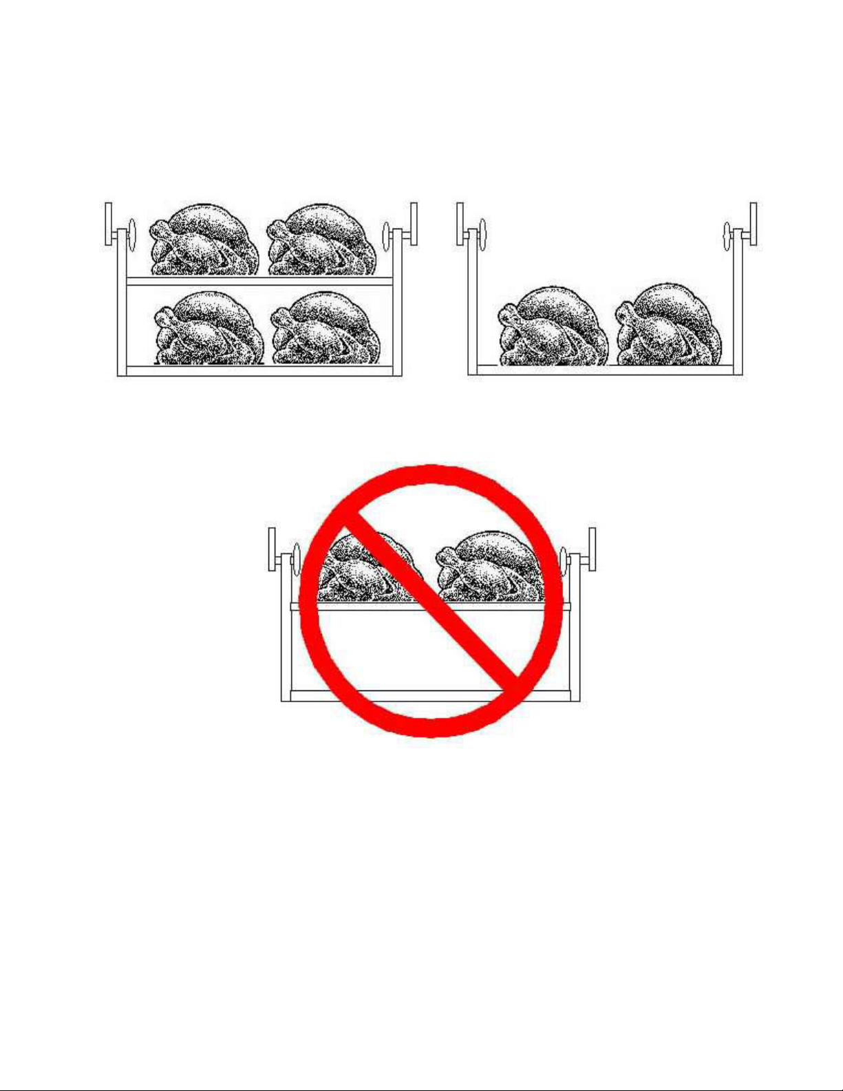
ROTISSERIE
YES YES
NO
To Avoid “Dumping” Racks, Load the Racks Vertically
as well as Horizontally. NEVER put heavy product on
the top rack with empty or lightly loaded bottom rack.

Gas Piping and Venting Instructions
Gas Requirements
Flexible hose must be used for the installation of all Ole Hickory Pits. A manual shutoff valve MUST be supplied in the gas line between the unit and the meter in an easily
accessible location. A low-pressure regulator is required to maintain correct gas
pressure to the burner. Please include a drip leg or sediment trap in the gas supply
line. Installation shall be made with a connector that complies with the Standard for
Connectors for Moveable Gas Appliances, ANSI Z21.41-1987, and a quick disconnect
device that complies with the Standard for Quick Disconnect Devices for Use With Gas
Fuel, ANSI Z21.41-1978, and Addenda Z21.41a-1981 and Z21.41b-1983. Once unit is
installed, PLEASE BE SURE TO LOCK CASTERS IN PLACE to prevent movement of the
unit. Casters may be removed for stationary installation.
Natural Gas: minimum supply pressure is 4.5 “W.C.”
maximum supply pressure is 10.5 “W.C.”
L.P. Gas: minimum supply pressure is 11.0 “W.C.”
maximum supply pressure is 13.0 “W.C.”
All piping must comply with local codes and ordinances or the National Fuel Gas Code
ANSI 23.1-1984 and NFPA No. 54.
A union shall be installed in the gas line adjacent to and upstream from the control
manifold and downstream from the manual main shutoff valve.
A 1/8" N.P.T. plugged tapping accessible for test gauge connection shall be installed
immediately upstream of the gas supply connection for the purpose of determining
the gas supply pressure to the burner.
The unit and its individual shutoff valve must be disconnected from the gas supply
piping system during any pressure testing of the system at test pressures in excess of
one half psig.
The unit must be isolated from the gas supply piping system by closing its in piping
system individual manual shutoff valve during any pressure testing of the gas supply
at test pressures equal to or less than one half psig.
Venting
Flues are required to extend 3 feet above the highest point where they pass through
the roof and at least 2 feet higher than any portion of a building within 10 feet. Flues
should be installed in an upward direction. Care should be given to avoid right angle,
elbow turns and the like that may restrict proper ventilation. A rain cap must be
utilized on a flue exhaust. A 4 foot flue extension is required for all units used
outdoors. Your flue extension rests inside the flue collar.

Electrical Specifications
Specifications:
120 Volts, 60 HZ, 1 Phase
AVOID NON-GROUNDED EXTENSION CORDS
15 amp Wiring
Instructions:
1. Electrical receptacles must be wired in accordance with local codes and
supplied by a qualified electrician.
2. All switches should be in the “OFF” position prior to power cord plug
insertion into receptacle.
Equipment:
1. One standard 1/4 horse motor drives the gear reducer (96 tooth sprocket)
for rotisserie operation.
2. One 1/4 horse 1,625 RPM motor for convection fan.
3. Gas burner is equipped with an electrical igniter system. (See complete
burner instructions)
Caution:
Burner electrical system is wired through an upper limit switch, which is preset at
350 degrees F. If the temperature inside the cooking chamber exceeds 350 degrees
F., the upper limit switch will not allow the burner to fire again until the upper limit
button, located under the service access panel, is manually reset. THE THERMOSTAT
IS NOT DESIGNED TO REDUCE TEMPERATURE IF FIRE GETS TOO HOT FROM
EXCESSIVE WOOD USAGE.

General Specifications
Dimensions:
Over-all Length: 8' 7"
Depth: 4' 7" Plus door handle clearance (with cooking chamber
Height: 6' 6-1/2" (with flue coupling; includes 6-1/2" casters)
Weight: 2100 pounds
Materials:
Basic Frame: 12 gauge steel, welded to 2" tubular steel 1/8" thick
Front: 22 gauge stainless steel, type 304 # 4 finish
Sides, Top & Front: 22 gauge stainless steel
Firebox Door: 1/4" steel plate, 21" h., 21"w.
door open: 6' 10")
square steel legs
Rack Levels:
Chrome wire (Stainless steel available at extra charge)
(15) each rack is 12" x 42"
Total Cooking Surface Area: 52.5 Sq. Ft.
Insulation:
Mineral Wool Rated to 1500 degrees F.
(Contains NO Asbestos)
Top & Side: 1" thick
Back: 1-1/2" thick
Front & Doors: 2" thick
Rotisserie:
Chain driven from 1/4 horse motor and reduction gear.

Maintenance & Cleaning
BEFORE PERFORMING ANY MAINTENANCE OR CLEANING
MAKE SURE UNIT IS DISCONNECTED FROM POWER SUPPLY
AND GAS IS TURNED OFF !
REFER SERVICING TO QUALIFIED PERSONNEL
1. a: Remove ashes and coals from firebox after each cooking. Ashes should be placed in a
non-combustible container and placed away from all combustible material. Make sure
there are in obstructions in the burner tube. USE EXTREME CAUTION WHEN CLEANING
THE BURNER TUBE TO NOT DAMAGE THE ELECTRODES OR OTHER PARTS INSIDE
BURNER TUBE.
b: Creosote-Formation and Need for Removable When wood is burned slowly, it
produces tar and other organic vapors, which combine with expelled moisture to form
creosote. The creosote vapors condense in the relatively cool chimney flue of a slowburning fire. As a result, creosote residue accumulates on the flue lining. When ignored,
this creosote makes an extremely hot fire. The chimney connector and chimney should
be inspected at least twice monthly to determine if a creosote buildup has occurred. If
creosote has accumulated. It should be removed to reduce the risk of a chimney fire.
2. Grease should be drained from the unit DAILY. Please dispose of grease in an approved
disposal container. Caution: Grease may be Hot !
3. Remove and clean cooking racks. To remove racks lift up on the right side of rack and
slide as far left as possible. Pull rack forward till it is free of pivot arm. Lift off left side of
rack and remove from unit.
4. Thoroughly clean complete interior and racks with a food service non-flammable
degreaser. Rinse with water and drain through drain valve on unit. Dispose of waste
properly. Make sure the drain is closed after cleaning.
5. Bi-weekly greasing of the bearings is necessary for proper operation of the unit.
Rotisserie shaft bearings are easily accessible and can be greased with a hand grease
gun.
6. Remove service access panels and inspect burner for accumulation of creosote or ashes.
Clean if needed. Check sprocket for broken or worn teeth. Check alignment of sprockets.
Replace service access panels when complete.
7. Check gasket material around cooking chamber doors and firebox for damage. Replace if
needed.
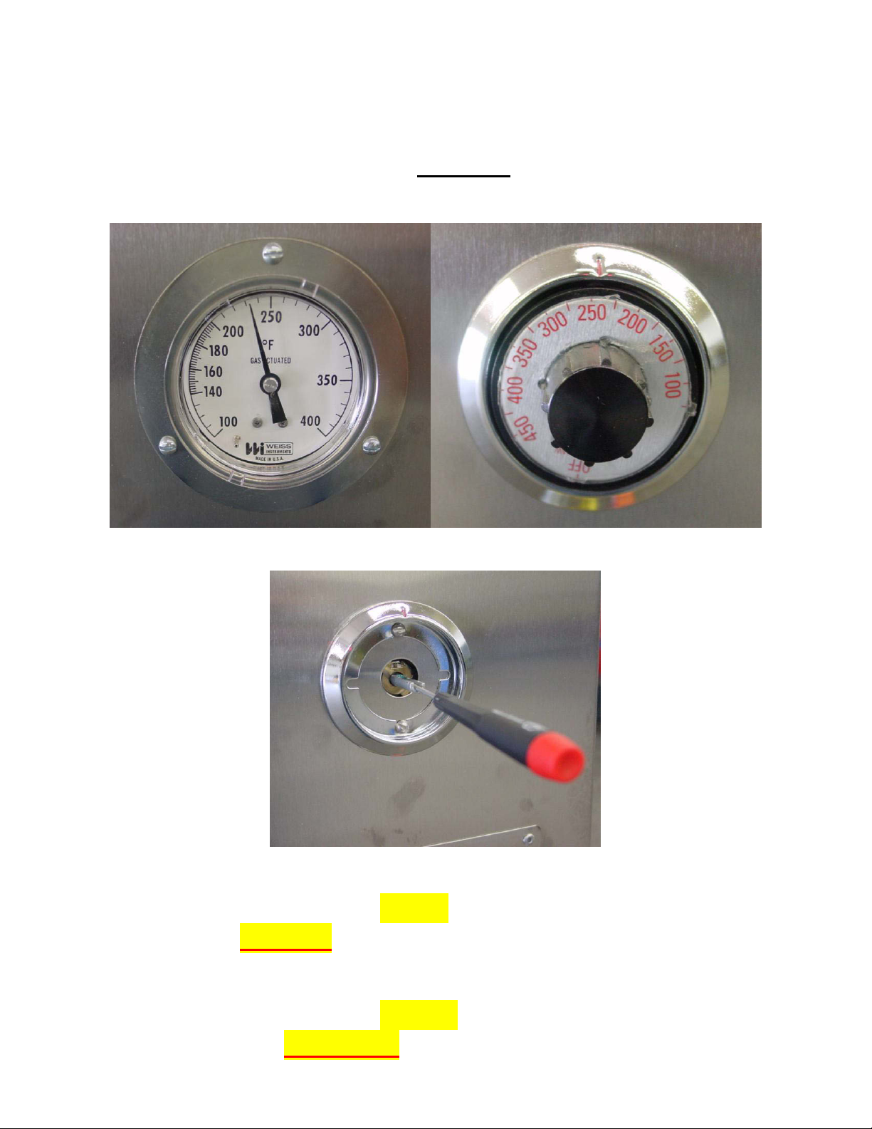
How To Calibrate The Thermostat
After the smoker has heated for about an hour, if the
Thermometer & Thermostat DO NOT agree…
Follow This Procedure:
Thermometer Thermostat
After removing knob, locate the screw inside the shaft.
If the thermometer reads lower than the thermostat, turn
slotted screw counter clockwise, no more than 1/8 turn at a
time.
If the thermometer reads higher than the thermostat, turn
the slotted screw clockwise, no more than 1/8 turn at a time.
 Loading...