


Warranty
Procedure IMPORTANT
Please Read
Should there be a mechanical problem with your warrantied unit(s) Monday through Friday, follow
the procedure below.
1. Call our Service Manager, Kevin Kessel, at 1-800-223-9667 between the hours of 8:00
am - 5:00 pm, Monday thru Friday CST. Give Kevin your Model and Serial Number of
your unit.
2. Explain the problem. Most often the problem can be handled by the Service Manager.
If the problem requires a service company, OHP Service Manager will contact the
service company, ascertain the work needed, issue an authorization number to the
service company and contact you with date, time and service work that has been preapproved.
3. After pre-assigned service has been completed, call the OHP Service Manager to make
sure defective parts are returned and all work has been completed.
Should there be a mechanical problem with your warrantied unit(s) during the weekend or any
holidays that OLE HICKORY PITS home office is not opened, follow the procedure below.
1. Call our office at 1-800-223-9667 and leave message containing Name, Address, Business
Name, Model, Serial # and mechanical problem. Also leave the name and phone number
of the pre-approved service company you will be using.
2. Contact your pre-approved service company.
3. Contact OLE HICKORY PITS, during the next regular business day that the required work
has been completed and defective parts have been returned.
Failure to follow the above may result in warranty claim being denied.
* Also read and follow the LIMITED WARRANTY Page in this manual.
REV110928

Do not store or use gasoline or other flammable vapors or liquids in the vicinity of this or any other
appliances.
OLE HICKORY PITS
333 North Main Street
Cape Girardeau, MO 63701
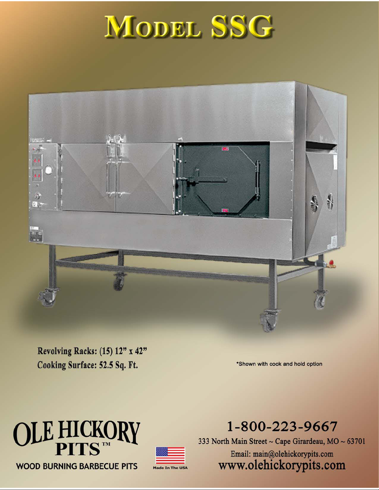
Owner’s Manual for Model SSG
Installation & Operating Instructions
Notice: These instructions should be affixed to the unit or adjacent to your Ole Hickory Pit
Please retain this manual for future reference
Notice: Installation must conform with local codes, or in the absence of local codes, with the
National Fuel Gas Code, ANSI Z223.1-1992, including
1) The unit and its individual shutoff valve must be disconnected from the gas supply
piping system during any pressure testing of that system at test pressures in excess of
one half psig.
2) The unit must be isolated from the gas supply piping system by closing its individual
manual shutoff valve during any pressure testing of the gas supply piping system at
test pressures equal to or less than one half psig.
Notice: This unit must be electrically grounded in accordance with local codes, or in the
absence of local codes, with the National Electrical Code, ANSI/NFPA 70-1990.
FOR YOUR SAFETY
Keep the unit free of combustible material. Allow 18" clear space around access panels.
If you smell gas: 1) Open Windows
2) Don’t Touch Electrical Switches
3) Extinguish Any Open Flame
4) Immediately Call Your Gas Supplier
Electrical Instructions: This appliance is equipped with a three-prong (grounding) plug for your
protection against shock hazard and should be plugged directly into a properly grounded three-prong
receptacle. DO NOT CUT OR REMOVE THE GROUNDING PRONG FROM THIS PLUG.
Warning - Exterior Surfaces May Be Hot
WARNING: This unit must be properly vented and used in an area where there is sufficient
dilution air to prevent concentration of CO from occurring.
Do Not Obstruct The Flow of Combustion and Ventilation Air Around Unit
Allow Adequate Clearances For Servicing and Proper Operation

WARNING; Improper installation, adjustment, alteration, service or maintenance can
cause property damage, injury or death. Read the installation, operating and maintenance
instructions thoroughly before installing or servicing this equipment.
Model SSG
Please Read All Instructions Thoroughly
Installation Instructions:
These instructions were prepared for the guidance of those installing this particular
gas and wood burning barbecue pit. While they apply in principle to most installations, they
should not be interpreted as meaning the only safe and economical way to install the unit. It
may be necessary to deviate from these instructions in some instances in order to comply
with local codes in effect in your area. We recommend the installer confer with the proper
local municipal officials regarding any specific code regulations. Installation should be
performed by a qualified installer.
VISUALLY INSPECT THE INSTALLATION LOCATION: An Ole Hickory Pit shall not be
installed in any location where facilities for normal air circulation or infiltration are so
limited so as to interfere with ready obtainment of all air necessary for proper ventilation
and draw.
Ole Hickory Pits must be secured for stationary installation on a level; impervious
floor (concrete or comparable). Floor has to support 2100 to 2600 pounds at all times. The
unit is suitable for installation on a combustible floor.
‘NOTICE; If your Ole Hickory Pit is to be installed with casters, it must be installed
with the casters supplied, a connector complying with either ANSI Z21.69 or CAN/CGA-6.16
and a quick-disconnect device complying with either ANSI Z21.41 or CAN1-6.9. It must also
be installed with restraining means to guard against transmission of strain to the connector,
as specified in the appliance manufacturer’s instructions.” Adequate means has been
provided to limit the movement of the unit without depending on the connector and the
quick disconnect device or its associated piping to limit oven movement. PLEASE LOCK
CASTERS ONCE UNIT IS IN PLACE.
A manual shutoff valve MUST be supplied in the gas line between the unit and the
meter in an easily accessible location. A regulator is required to maintain correct gas
pressure to burner. Please include a drip leg or sediment trap in the gas supply line.
INSPECTION AND PREPARATION OF UNIT. Visually inspect the Ole Hickory Pit by
removing the service access panels and ensure that motors and burner have not been
loosened during shipment of unit. Replace the service panels after inspection. The racks in
the cooking chamber should be properly set in position.
Before proceeding with installation, read all instructions carefully and make sure all
switches are set to the “OFF” position.

SAFETY TIPS
Please Read & Follow All Safety Instructions!
1. The area surrounding the Ole Hickory Pit MUST be kept clear of combustible materials. DO NOT
STORE OR USE GASOLINE OR OTHER FLAMMABLE VAPORS OR LIQUIDS IN THE VICINITY OF THIS
OR ANY OTHER APPLIANCE.
2. Ventilating air MUST NOT be obstructed from reaching the pit. Adequate makeup air and
ventilation are required to keep motors cool and allow proper operation of the burner.
3. At time of installation, the unit must be electrically grounded in accordance with local codes. In
the absence of local codes, please refer to the National Electrical Code, ANSI/NFPA 70-1996.
4. The service access panels should be properly installed and maintained in place during operation
of the unit. Should servicing be required, make sure the gas supply to the unit is turned off and
that the unit is unplugged before removing service panels.
5. NO ADJUSTMENTS TO THE POWER BURNER SHOULD BE MADE BY USER. If the burner does not
appear to be operating properly, turn gas supply off and contact Ole Hickory Pits or a qualified
serviceman for repairs.
6. Service work performed by unqualified personnel may void the warranty. Please do not allow
adjustments to be made to the unit that would alter the operation or disable the built in safety
features. Such alterations may result in a hazardous condition.
7. Flues are required on ALL Ole Hickory Pits. Failure to do so will result in unit malfunction and
substandard performance. (See the Gas Piping and Venting Instructions page)
8. This unit is suitable for installation on combustible floors.
9. Failure to follow recommended cleaning and maintenance procedures might also result in
hazardous conditions and void equipment warranty.
10. Please note on Fire Box: “Warning-Hot Surface Do Not Touch”
11. Please instruct all persons using this equipment on the proper use and maintenance.
12. Please maintain a minimum safety clearance from surrounding materials as follows:
Combustible Construction Noncombustible construction
Back: * 2" 2"
Right Side: * 18" 18"
Left Side: 18" 18"
Top: 2” 2”
Bottom: 6” 6”
*Indicates clearance needed for servicing and maintenance of smoker.
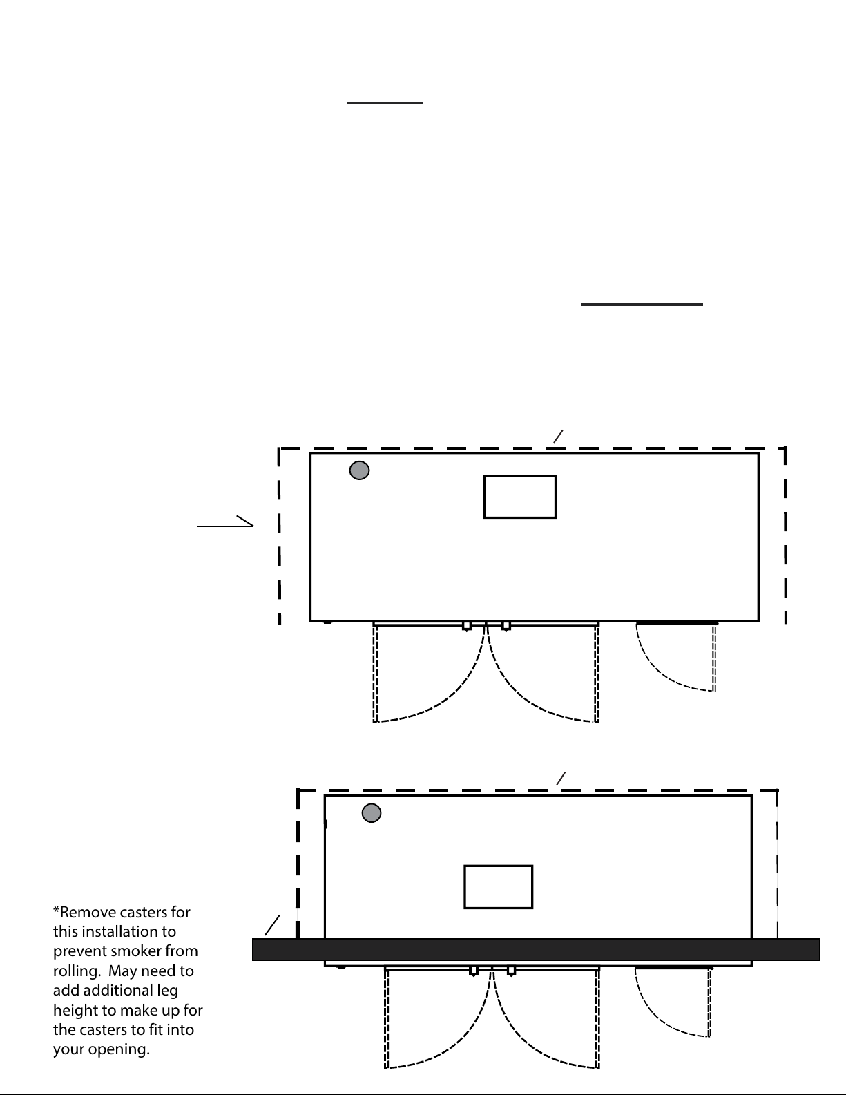
Models SSM, SSG, SSL & SSE Top View
Showing Clearance, Page 3 of Owners Manual, Titled Safety Tips:
#12. Please maintain a MINIMUM safety or mechanical clearance
from surrounding materials as follows:
Combustible Construction: Back 2"
Right S
Left S
Noncombustible Construction: Back: 2"
Right S
Left S
Any Installation that does not allow for the proper MINIMUM
Safety or Mechanical Clearance, as per ETL, may be considered a
Non-Approved Installation by Ole Hickory Pits. A Non-Approved
ide: 18"
ide: 18"
ide: 18"
ide: 18"
Installation ma
Example 1:
Free Standing
Inside or Outside
Bu
liding.
y void your warranty.
18"
2"
Smoke Evac.
Opening
18"
2"
Example 2:
Faced Thru Wall
Installation
*Remove casters for
this installation to
prevent smoker from
rolling. May need to
add additional leg
height to make up for
the casters to fit into
your opening.
Outside
Wall
18"
18"
Smoke Evac.
Opening

Operating Instructions
1. Preheat the Ole Hickory Pit to desired temperature by turning on all switches found on
the control panel. Recommended cooking temperature is 225 degrees F. and CANNOT
exceed 350 degrees F.
WARNING: Unit is equipped with an upper limit switch
that will shut down all operations until the
reset button, located under the service panel,
is manually reset.
Disconnect Power Before Removing Panel.
2. During the heating process, prepare the product to be cooked.
3. Begin loading the unit on the bottom racks first and evenly distribute the weight of the
product on all racks. DO NOT allow any of the product to hang over the front or back
edges or the racks. This may cause racks to tip and jam the rotisserie. If the product is
too large for the bottom rack, remove the top rack and load the product on the bottom
rack.
4. To advance the racks with the cooking chamber doors open, depress the Rotisserie Foot
Advance until the racks are advanced to the next position.
5. After, loading, allow the rotisserie to complete two revolutions to check for adequate
clearance of the product to the walls of the cooking chamber and racks. Reposition
product if necessary.
6. Wood used should be 4" to 10" in diameter and 16" to 24" in length. DO NOT ALLOW
ASHES OR LOGS TO OBSTRUCT THE BURNER TUBE OPENING. It is recommended to use
no more than 2 or 3 sticks of wood for a complete cooking cycle. Excessive amounts of
wood usage will overheat the cooking chamber and may trip the Upper Limit Switch.
7. When checking the meat, upon opening of the cooking chamber doors, the burner, and
convection systems are disabled. When the doors are closed, all systems are reactivated.
8. IN CASE OF POWER FAILURE: Turn off gas supply to unit. To prevent product spoilage if
cooking, the inside temperature of the unit can be maintained by manually keeping wood
in the firebox.
9. Contact factory, the factory representative or a local service company to perform
maintenance and repairs.
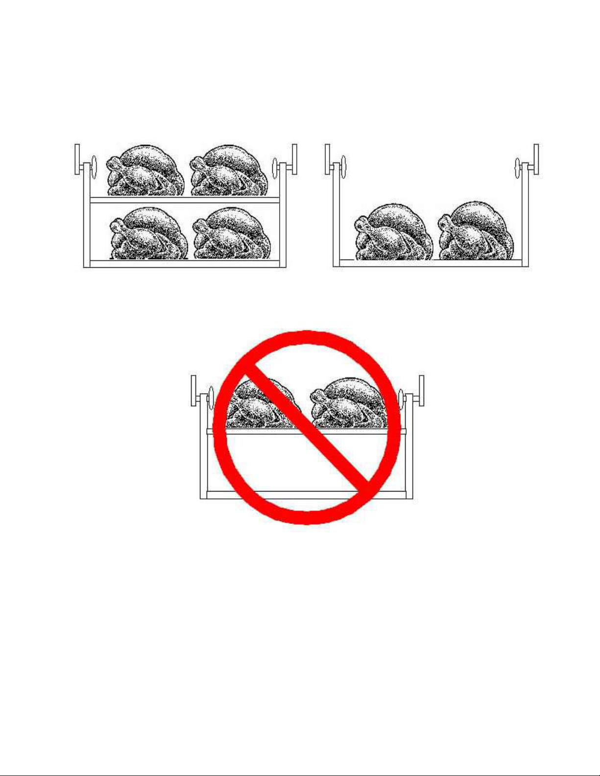
ROTISSERIE
YES YES
NO
To Avoid “Dumping” Racks, Load the Racks Vertically
as well as Horizontally. NEVER put heavy product on
the top rack with empty or lightly loaded bottom rack.

Gas Piping and Venting Instructions
Gas Requirements
Flexible hose must be used for the installation of all Ole Hickory Pits. A manual shutoff valve MUST be supplied in the gas line between the unit and the meter in an easily
accessible location. A low-pressure regulator is required to maintain correct gas
pressure to the burner. Please include a drip leg or sediment trap in the gas supply
line. Installation shall be made with a connector that complies with the Standard for
Connectors for Moveable Gas Appliances, ANSI Z21.41-1987, and a quick disconnect
device that complies with the Standard for Quick Disconnect Devices for Use With Gas
Fuel, ANSI Z21.41-1978, and Addenda Z21.41a-1981 and Z21.41b-1983. Once unit is
installed, PLEASE BE SURE TO LOCK CASTERS IN PLACE to prevent movement of the
unit. Casters may be removed for stationary installation.
Natural Gas: minimum supply pressure is 4.5 “W.C.”
maximum supply pressure is 10.5 “W.C.”
L.P. Gas: minimum supply pressure is 11.0 “W.C.”
maximum supply pressure is 13.0 “W.C.”
All piping must comply with local codes and ordinances or the National Fuel Gas Code
ANSI 23.1-1984 and NFPA No. 54.
A union shall be installed in the gas line adjacent to and upstream from the control
manifold and downstream from the manual main shutoff valve.
A 1/8" N.P.T. plugged tapping accessible for test gauge connection shall be installed
immediately upstream of the gas supply connection for the purpose of determining
the gas supply pressure to the burner.
The unit and its individual shutoff valve must be disconnected from the gas supply
piping system during any pressure testing of the system at test pressures in excess of
one half psig.
The unit must be isolated from the gas supply piping system by closing its in piping
system individual manual shutoff valve during any pressure testing of the gas supply
at test pressures equal to or less than one half psig.
Venting
Flues are required to extend 3 feet above the highest point where they pass through
the roof and at least 2 feet higher than any portion of a building within 10 feet. Flues
should be installed in an upward direction. Care should be given to avoid right angle,
elbow turns and the like that may restrict proper ventilation. A rain cap must be
utilized on a flue exhaust. A 4 foot flue extension is required for all units used
outdoors. Your flue extension rests inside the flue collar.

Electrical Specifications
Specifications:
120 Volts, 60 HZ, 1 Phase
AVOID NON-GROUNDED EXTENSION CORDS
15 amp Wiring
Instructions:
1. Electrical receptacles must be wired in accordance with local codes and
supplied by a qualified electrician.
2. All switches should be in the “OFF” position prior to power cord plug
insertion into receptacle.
Equipment:
1. One standard 1/4 horse motor drives the gear reducer (96 tooth sprocket)
for rotisserie operation.
2. One 1/4 horse 1,625 RPM motor for convection fan.
3. Gas burner is equipped with an electrical igniter system. (See complete
burner instructions)
Caution:
Burner electrical system is wired through an upper limit switch, which is preset at
350 degrees F. If the temperature inside the cooking chamber exceeds 350 degrees
F., the upper limit switch will not allow the burner to fire again until the upper limit
button, located under the service access panel, is manually reset. THE THERMOSTAT
IS NOT DESIGNED TO REDUCE TEMPERATURE IF FIRE GETS TOO HOT FROM
EXCESSIVE WOOD USAGE.

General Specifications
Dimensions:
Over-all Length: 8' 7"
Depth: 4' 7" Plus door handle clearance (with cooking chamber
Height: 6' 6-1/2" (with flue coupling; includes 6-1/2" casters)
Weight: 2100 pounds
Materials:
Basic Frame: 12 gauge steel, welded to 2" tubular steel 1/8" thick
Front: 22 gauge stainless steel, type 304 # 4 finish
Sides, Top & Front: 22 gauge stainless steel
Firebox Door: 1/4" steel plate, 21" h., 21"w.
door open: 6' 10")
square steel legs
Rack Levels:
Chrome wire (Stainless steel available at extra charge)
(15) each rack is 12" x 42"
Total Cooking Surface Area: 52.5 Sq. Ft.
Insulation:
Mineral Wool Rated to 1500 degrees F.
(Contains NO Asbestos)
Top & Side: 1" thick
Back: 1-1/2" thick
Front & Doors: 2" thick
Rotisserie:
Chain driven from 1/4 horse motor and reduction gear.

Maintenance & Cleaning
BEFORE PERFORMING ANY MAINTENANCE OR CLEANING
MAKE SURE UNIT IS DISCONNECTED FROM POWER SUPPLY
AND GAS IS TURNED OFF !
REFER SERVICING TO QUALIFIED PERSONNEL
1. a: Remove ashes and coals from firebox after each cooking. Ashes should be placed in a
non-combustible container and placed away from all combustible material. Make sure
there are in obstructions in the burner tube. USE EXTREME CAUTION WHEN CLEANING
THE BURNER TUBE TO NOT DAMAGE THE ELECTRODES OR OTHER PARTS INSIDE
BURNER TUBE.
b: Creosote-Formation and Need for Removable When wood is burned slowly, it
produces tar and other organic vapors, which combine with expelled moisture to form
creosote. The creosote vapors condense in the relatively cool chimney flue of a slowburning fire. As a result, creosote residue accumulates on the flue lining. When ignored,
this creosote makes an extremely hot fire. The chimney connector and chimney should
be inspected at least twice monthly to determine if a creosote buildup has occurred. If
creosote has accumulated. It should be removed to reduce the risk of a chimney fire.
2. Grease should be drained from the unit DAILY. Please dispose of grease in an approved
disposal container. Caution: Grease may be Hot !
3. Remove and clean cooking racks. To remove racks lift up on the right side of rack and
slide as far left as possible. Pull rack forward till it is free of pivot arm. Lift off left side of
rack and remove from unit.
4. Thoroughly clean complete interior and racks with a food service non-flammable
degreaser. Rinse with water and drain through drain valve on unit. Dispose of waste
properly. Make sure the drain is closed after cleaning.
5. Bi-weekly greasing of the bearings is necessary for proper operation of the unit.
Rotisserie shaft bearings are easily accessible and can be greased with a hand grease
gun.
6. Remove service access panels and inspect burner for accumulation of creosote or ashes.
Clean if needed. Check sprocket for broken or worn teeth. Check alignment of sprockets.
Replace service access panels when complete.
7. Check gasket material around cooking chamber doors and firebox for damage. Replace if
needed.
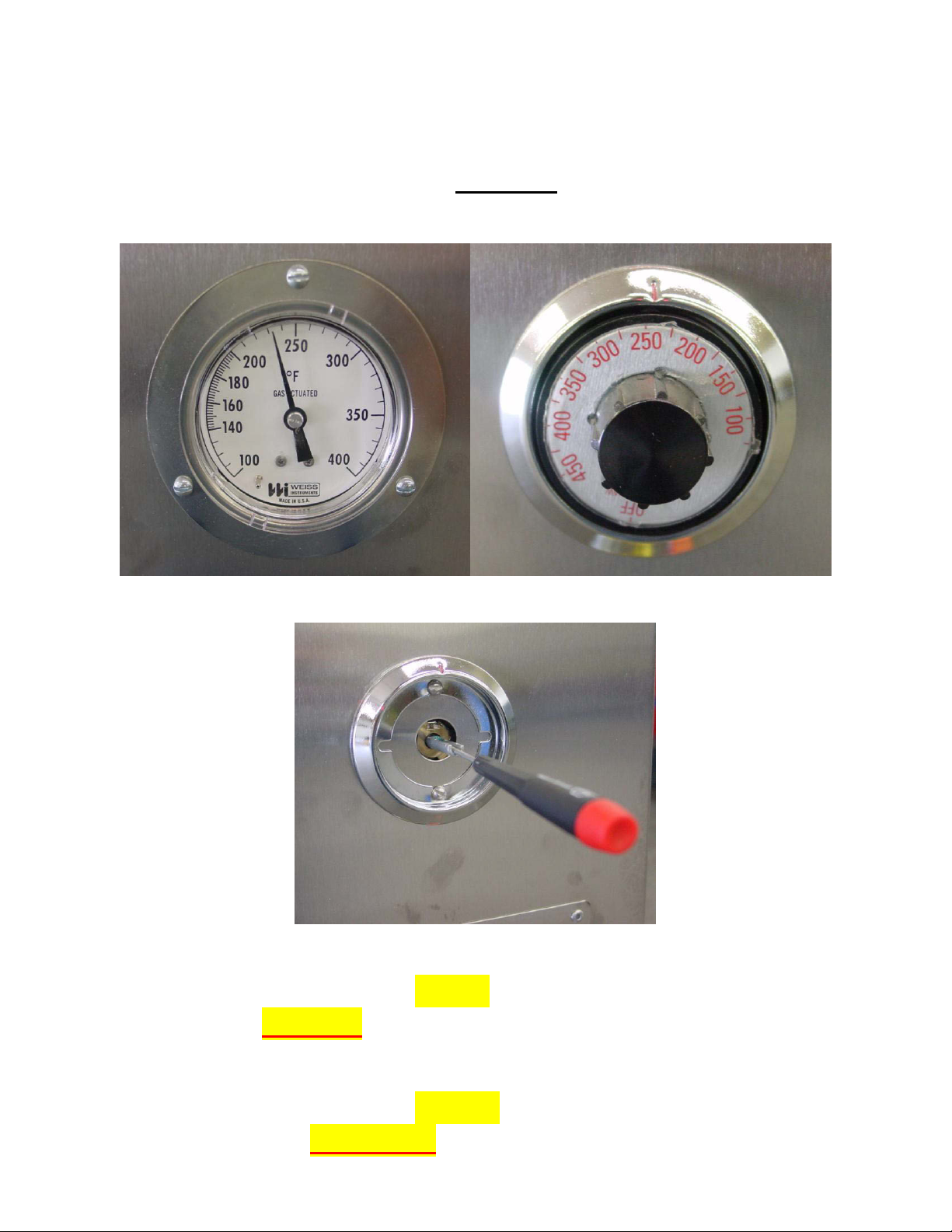
How To Calibrate The Thermostat
After the smoker has heated for about an hour, if the
Thermometer & Thermostat DO NOT agree…
Follow This Procedure:
Thermometer Thermostat
After removing knob, locate the screw inside the shaft.
If the thermometer reads lower than the thermostat, turn
slotted screw counter clockwise, no more than 1/8 turn at a
time.
If the thermometer reads higher than the thermostat, turn
the slotted screw clockwise, no more than 1/8 turn at a time.

Limited Warranty
Ole Hickory Pits warrants its product and components to be free from defects due to
faulty workmanship or defective materials at time of shipment and under normal use and
service for twelve (12) months from the date of delivery. This LIMITED WARRANTY does not
extend or apply to Ole Hickory Pits, or any component thereof, which has been misused,
neglected, improperly installed or otherwise abused. IT IS THE CUSTOMER’S RESPONSIBILITY
TO MAINTAIN ADEQUATE MAKE UP AIR. FAILURE TO DO SO CAN RESULT IN A HAZARDOUS
SITUATION AS WELL AS VOIDING THE WARRANTY. Equipment which is defective in material
or workmanship and which is removed within the specific time period will be repaired or
replaced as follows:
____________ (1) All service work to be performed is to be pre-approved by Ole Hickory Pits
PRIOR to the service call.
____________ (2) Only ORIGINAL equipment parts should be used in the repair of the unit. Other
parts used as replacement parts will void warranty.
____________ (3) Controls, motors, or other components which are so repaired or replaced will
carry this LIMITED WARRANTY equal to the unexpired portion of the original
product LIMITED WARRANTY.
____________ (4) Ole Hickory Pits is NOT responsible for any labor beyond the PRE-APPROVED
limit. Overtime rates and excessive labor will be the responsibility of the
customer.
____________ (5) Upon return of malfunctioning product, if inspection by Ole Hickory Pits does
not disclose any defect covered by this LIMITED WARRANTY, the product will
be repaired or replaced at the expense of the customer and Ole Hickory Pits
regular charges will apply.
____________ (6) Replacement parts covered under warranty will be shipped from our factory,
located in Cape Girardeau, MO, by REGULAR ground service at no cost to the
customer. Any request for overnight shipping to the customer’s location will be
billed to the CUSTOMER in the amount of the additional charges to comply with
the customer’s special request.
____________ (7) All parts replaced under this LIMITED WARRANTY must be returned to Ole
Hickory Pits within 30 days of service work or Ole Hickory Pits reserves the
right to deny warranty coverage.
THE FOREGOING STATES THE SOLE AND EXCLUSIVE REMEDY FOR ANY BREACH OF
WARRANTY OR FOR ANY OTHER CLAIM BASED ON ANY DEFECT IN, OR NON-PERFORMANCE
OF, THE PRODUCTS, WHETHER IN CONTACT, WARRANTY OR NEGLIGENCE. NO OTHER
WARRANTY, WHETHER EXPRESSED OR IMPLIED, INCLUDING ANY WARRANTY OF
MERCHANTABILITY OR FITNESS FOR A PARTICULAR PURPOSE, SHALL EXIST IN CONNECTION
WITH THE SALE OR USE OF SUCH PRODUCTS AND IN NO EVENT WILL OLE HICKORY PITS BE
LIABLE FOR ANY INCIDENTAL OR CONSEQUENTIAL DAMAGES OF FUTURE NATURE. Ole
Hickory Pits neither assumes nor authorizes any person to assume for Ole Hickory Pits any
other liability or obligation in connection with the sale of these products.
Customer Signature:______________________________________________________Date:______________________________
Your signature constitutes understanding and acceptance of the above terms of the Warranty Agreement.

***IMPORTANT***
READ CAREFULLY
POSITIVE AIR FLOW through the air
shutter on the burner MUST be maintained
for safe and proper operation of the unit(s).
Burner air flow may be affected by one or
a combination of the following.
1. Improper flue installation.
2. Inadequate makeup air for hood
systems or exhaust fans.
3. Competing hood systems or
ventilation in the building.
4. Extreme drafts or inadequate
clearance.
If there are questions, consult your
owners manual or call 1-800-223-9667 for
support.

BURNER INSTRUCTIONS
ALLOW A FIVE (5) MINUTE COMPLETE SHUTOFF
PERIOD BEFORE APPLIANCE IS RE-LIGHTED.
Initial Start of Burner:
1. Remove service access panel.
2. Check burner for proper connection to gas lines.
3. Turn gas supply to burner on.
4. Depress the gas valve control knob on the combination
gas valve and turn to on position.
5. Replace service access panel.
6. Turn on burner switch located on front control panel.
7. Set thermostat to desired temperature.
To Put Burner Out of Operation for an Extended
Period:
1. Set all switches located on front of unit to “OFF” position.
2. Unplug unit from electrical source.
3. Turn gas supply off.
4. Depress the gas valve control knob on the combination
gas valve and turn to off position.
5. Replace service access panel.

PURPOSE
The purpose of the Smoke Evacuator System is to remove smoke from the front-loading
area of the unit once the doors are opened and prevent excess smoke from escaping
into the kitchen or food processing area. This enables the operator to work
unobstructed by interference from escaping smoke and heat. The smoke will be drawn
from the inside of the unit as opposed to an externally mounted hood system.
OPERATION
The procedure for operating the Smoke Evacuator System is quite simple. First,
activate the smoke evacuator by pressing in on the Black “ON” button and continue to
hold for 5 seconds. Second, while holding the Black “ON” button in for 5 seconds, grasp
door handle to cooking chamber. After the initial 5 seconds, slowly open the cooking
chamber door; operator may now release push button. The smoke evacuator will
remain on while the cooking chamber door is open. The smoke evacuator will
automatically turn off when the operator closes the door to the cooking chamber and
the unit will return to normal operating.
SMOKE EVACUATOR
(Push Button)
(Optional Equipment)
COMPONENTS
The Evacuator System is made up of four (4) basic components: (1) the switch, (2) the
Evacuator (power damper), (3) the 10” diameter duct and (4) the ventilator fan. Items
(1) and (2) are sold by Ole Hickory Pits as optional equipment. Items (3) and (4) are
purchased by you and are of your installation responsibility. ADEQUATE MAKEUP
AIR IS REQUIRED FOR SAFE OPERATION. Consult manual for more information.
It is your responsibility to maintain essential combustion air at all times during
operation of the unit.
INSTALLATION
Attach the 10” diameter duct to the 10” diameter duct collar located on the top of the
Evacuator. Check with your local inspector to make sure the duct complies with local
codes. The duct will go through your roof and will attach to the ventilator fan above
the roof. The ventilator fan can then be wired into your units relay system, thus
allowing your switch to activate the Evacuator and the ventilator fan at the same time.
As always, use a qualified local contractor for your installation.

AUTHORIZATION TO MARK
y
This authorizes the application of the Certification Mark(s) shown below to the models described in the Product(s)
Covered section when made in accordance with the conditions set forth in the Certification Agreement and Listing
Report. This authorization also applies to multiple listee model(s) identified on the correlation page of the Listing
Report.
This document is the property of Intertek Testing Services and is not transferable. The certification mark(s) may be
applied only at the location of the Party Authorized To Apply Mark.
Applicant: Manufacturer:
Address: Address:
Countr
Contact: Contact:
Phone: Phone:
FAX: FAX:
Email: Email:
Party Authorized To Apply Mark:
Report Issuing Office:
Control Number:
Ole Hickory Pits
333 North Main St
Cape Girardeau, MO 63701
USA USA
: Country:
Mr. David Scherer
(800) 223-9667 (573) 334-3377
(573) 334-2507 NA
NA
Same as Manufacturer
Arlington Heights
5006430
Authorized by:
for Dean Davidson, Certification Manager
David B. Knight & Associates, Inc, DBA
Ole Hickory Pits
4077 Nash Road
Cape Girardeau, MO 63701
Mr. David Scherer
Mr. Kevin Kessel
kdscherer@olehickorypits.com
kevin@olehickorypitss.com
This document supersedes all previous Authorizations to Mark for the noted Report Number.
This Authorization to Mark is for the exclusive use of Intertek's Client and is provided pursuant to the Certification agreement between Intertek and its Client. Intertek's responsibility and liability are
limited to the terms and conditions of the agreement. Intertek assumes no liability to any party, other than to the Client in accordance with the agreement, for any loss, expense or damage occasioned
by the use of this Authorization to Mark. Only the Client is authorized to permit copying or distribution of this Authorization to Mark and then only in its entirety. Use of Intertek’s Certification mark is
restricted to the conditions laid out in the agreement and in this Authorization to Mark. Any further use of the Intertek name for the sale or advertisement of the tested material, product or service must
first be approved in writing by Intertek. Initial Factory Assessments and Follow up Services are for the purpose of assuring appropriate usage of the Certification mark in accordance with the
agreement, they are not for the purposes of production quality control and do not relieve the Client of their obli gations in this respect.
Intertek Testing Services NA Inc.
545 East Algonquin Road, Arlington Heights, IL 60005
Telephone 800-345-3851 or 847-439-5667 Fax 312-283-1672
Gas Food Service Equipment [ANSI Z83.11:2016 Ed.4]
Standard(s):
Gas Food Service Equipment [CSA 1.8:2016 Ed.4]
Product:
Models:
Indoor/Outdoor Gas Bar-Be-Que pits
EL, EL-ED, EL-ED/X, ELIB, EL-EW, ELEX, ELEC, ELES, ELVS, SDL, SDLX, SSE, SSG, SSI, SSJ, SSJAE, SSJ-EW, SSL, SSM, SRO, SSO, SSRD, VS3 and VS4
Page 2 of 2 ATM for Report 550536CHI-001
ATM Issued: 24-May-2018
ED 16.3.15 (20-Apr-17) Mandatory

AUTHORIZATION TO MARK
y
0
This authorizes the application of the Certification Mark(s) shown below to the models described in the Product(s)
Covered section when made in accordance with the conditions set forth in the Certification Agreement and Listing
Report. This authorization also applies to multiple listee model(s) identified on the correlation page of the Listing
Report.
This document is the property of Intertek Testing Services and is not transferable. The certification mark(s) may be
applied only at the location of the Party Authorized To Apply Mark.
Applicant: Manufacturer:
Address: Address:
Countr
Contact: Contact:
Phone: Phone:
FAX: FAX:
Email: Email:
Party Authorized To Apply Mark:
Report Issuing Office:
Control Number:
Ole Hickory Pits
333 North Main
Cape Girardeau, MO 63701
USA USA
: Country:
Mr. David Scherer
(573) 334-3377 (573) 334-3377
(573) 334-6512 NA
dscherer@olehickorypits.com
Same as Manufacturer
Chicago, IL
500643
Authorized by:
for Dean Davidson, Certification Manager
David B Knight & Associates, Inc.,
DBA Ole Hickory Pits
4077 Nash Road
Cape Girardeau, MO 63701
Mr. David Scherer
Kevin Kessel
dscherer@olehickorypits.com
kevin@olehickorypitss.com
This document supersedes all previous Authorizations to Mark for the noted Report Number.
This Authorization to Mark is for the exclusive use of Intertek's Client and is provided pursuant to the Certification agreement between Intertek and its Client. Intertek's responsibility and liability are
limited to the terms and conditions of the agreement. Intertek assumes no liability to any party, other than to the Client in accordance with the agreement, for any loss, expense or damage occasi oned
by the use of this Authorization to Mark. Only the Client is authorized to permit copying or distribution of this Authorization to Mark and then only in its entirety. Use of Intertek’s Certification mark is
restricted to the conditions laid out in the agreement and in this Authorization to Mark. Any further use of the Intertek name for the sale or advertisement of the tested material, product or service must
first be approved in writing by Intertek. Initial Factory Assessments and Follow up Services are for the purpose of assuring appropriate usage of the Certification mark in accordance with the
agreement, they are not for the purposes of production quality control and do not relieve the Client of their obli gations in this respect.
Intertek Testing Services NA Inc.
545 East Algonquin Road, Arlington Heights, IL 60005
Telephone 800-345-3851 or 847-439-5667 Fax 312-283-1672
Standard(s):
Product:
Models:
Commercial Cooking, Rethermalization, And Powered Hot Food Holding And Transportation Equipment
[NSF 4:2016 ]
Indoor/ Outdoor Gas Bar-Be-Que Pits
EL, EL-ED, EL-ED/X, ELIB, EL-EW, ELEX, ELEC, ELES, ELVS, SDL, SDLX, SSE, SSG, SSI, SSJ, SSJAE, SSJ-EW, SSL, SSM, SRO, SSO, SSRD, VS3 and VS4.
Page 2 of 2 ATM for Report 3098759CHI-001
ATM Issued: 18-Jan-2018
ED 16.3.14 (20-Apr-17) Mandatory

Report No. 550536CHI-001 Page 17 Issued: 06/13/95
David B. Knight & Associates, Inc, DBA Ole Hickory Pits Revised: 10/11/11
J) Minimum lettering height of 0.10 inch with a minimum vertical spacing between lines of 0.066 inch:
Minimum clearance from combustible construction minimum 2 inches from sides and back. Minimum
6” from floor.
K) Instructions for lighting and shutdown the appliance. Lighting instructions specify a 5-minute
complete shutoff period before the appliance is re-lighted.
L) "This equipment is to be installed to comply with the applicable Federal, state or local plumbing codes
having jurisdiction." and Cet équipement doit être installé pour se conformer aux codes de plomberie
applicable fédérale , provinciales ou locales ayant compétence"
M) The word "NOTICE" and "Avis" in letters having a minimum lettering height of .36 inches. The
remainder of the marking has a minimum lettering height of 0.180 inch with a minimum vertical
spacing between lines of 0.069 inch, the lettering is in black, on a yellow background, where visible
after installation:
"NOTICE: When this appliance is installed with casters, it must be installed with the casters supplied,
a connector complying with either ANSI Z21.69 or CAN/CGA-6.16 and a quick disconnect device
complying with either ANSI Z21.41 or CANI-69. It must also be installed with a restraining means to
guard against transmission of strain to the connector, as specified in the appliance manufacturer's
instructions." And “AVIS: Les appareils sur roulettes doivent être pourvus des roulettes fournies, d’un
tuyau de raccordement conforme à la norme ANSI Z21.69 ou CAN/CGA 6.16 et d’une raccord à
débrancement rapide satisfaisant les exigencies de la norme ANSI Z21.41 ou CAN1-6.9. lls doivent
aussi être minis d’un dispositif de retenue pour empêcher toute transmission de tension au tuyau de
raccordement confromément aux instructions du fabricant.” Provided only on units shipped with
casters.
N) "Warning" followed by "Electrical Grounding Instructions" followed by "This appliance is equipped
with a three-prong (grounding) plug for your protection against shock hazard and should be plugged
directly into a properly grounded three-prong receptacle. Do not cut or remove the grounding prong
from this plug." And “Cet appareil est pourva d’une fiche à trios broches dont une mise à la terre
assurant une protection contre les chocs électriques. La prise dans laquelle elle est branchée doit être
correctement mise à la terre. Ne pas couper ni enlever la broche de mise à la terre de la fiche.”
Provided only on units, which are cord connected to the supply source.
O) Wiring Diagram provided on the unit, where accessible during servicing of electrical components.
Provided only on units with electrical components.
P) Instructions for lubrication of the fan motor, or a statement that the bearings are permanently
lubricated, located on the fan housing
The minimum dimension for all letters of the word Caution or similar words conveying a warning are
3/32 inch (2.4 mm) high. "WARNING" and "Attention" in contrasting color from background.
Q) "EVAC Off/On" by EVAC motor switch when EVAC motors are used.
R) "CAUTION, Use Only Dry Seasoned Wood!" and “Attention N’utiliser que du bois sec” marked on
fire box door.
S) "Suitable for outdoor use" and "Convient pour une utilisation en extérieur"

Report No. 3098759CHI-001
Ole Hickory Pits
4.0 Critical Components
Photo #
Item
Name and
no.
1
location
2
Manufacturer/
trademark
3
Page 6 of 28
Material type /
4
model
Issued: 29-Jun-2006
Revised: 20-Dec-2017
Technical data and Acceptance
Mark(s) of
5
conformity
6
21
22
23
24
Food Rack, HFZ,
FC
Rack Support,
HFZ, NFC
Interior Top, HFZ,
NFC
Upper Interior
Sides (Above
lowest rack), HFZ,
NFC
Various
Various steel with
US Coatings Paint
Various steel with
PPG Industries
Powder Coating
Various steel with
US Coatings Paint
Various steel with
PPG Industries
Powder Coating
Various steel with
US Coatings Paint
Various steel with
PPG Industries
Powder Coating
Nickel Chrome
plated steel
Steel painted
black with
HeatGrip 4950
Steel painted
black with
Ebony
PCTT90119
Steel painted
black with
HeatGrip 4950
Steel painted
black with
Ebony
PCTT90119
Steel painted
black with
HeatGrip 4950
Steel painted
black with
Ebony
PCTT90119
Stainless steel
type 200 series
Stainless steel
type 300 series
Stainless steel
type 400 series
NSF/ANSI 51 - Section 6.1.1
ASTM B456-95
Impact , Abrasion and Heat
Resistance, NSF/ANSI 51Section 4.4.1, 9.2, 10.1, 11
Impact , Abrasion and Heat
Resistance, NSF/ANSI 51Section 4.4.1, 9.2, 10.1, 11 Verify
NSF Listing
Impact , Abrasion and Heat
Resistance, NSF/ANSI 51Section 4.4.1, 9.2, 10.1, 11
Impact , Abrasion and Heat
Resistance, NSF/ANSI 51Section 4.4.1, 9.2, 10.1, 11 Verify
NSF Listing
Impact , Abrasion and Heat
Resistance, NSF/ANSI 51Section 4.4.1, 9.2, 10.1, 11
Impact , Abrasion and Heat
Resistance, NSF/ANSI 51Section 4.4.1, 9.2, 10.1, 11 Verify
NSF Listing
NSF/ANSI 51- Section 4.2.1.1 NRVariousDoor Interior, SZ52
NR
NR
NSF
NR
NSF
NR
NSF
26
Interior Bottom,
SZ
Various steel with
US Coatings Paint
Various steel with
PPG Industries
Powder Coating
Steel painted
black with
HeatGrip 4950
Steel painted
black with
Ebony
PCTT90119
Impact , Abrasion and Heat
Resistance, NSF/ANSI 51Section 4.4.1, 9.2, 10.1, 11
Impact , Abrasion and Heat
Resistance, NSF/ANSI 51Section 4.4.1, 9.2, 10.1, 11 Verify
NSF Listing
ED 16.3.14 (20-Apr-17) Mandatory
NR
NSF

Report No. 3098759CHI-001
Ole Hickory Pits
4.0 Critical Components
Photo #
Item
Name and
no.
1
location
2
Manufacturer/
trademark
3
Page 7 of 28
Material type /
4
model
Issued: 29-Jun-2006
Revised: 20-Dec-2017
Technical data and Acceptance
Mark(s) of
5
conformity
6
Various steel with
US Coatings Paint
Interior Side
27
(Below lowest
rack), SZ
Various steel with
PPG Industries
Powder Coating
18
2,3 9 Door Gasket, SZ
Ball Valve - 2"
SZ
Various
MTI Specialty
Silicones
Outer Shelf,
(Optional not
101
Various NSF/ANSI 51- Section 4.2.1.1 NR
shown), SZ
1 11 Casters, NFZ Various
Steel, painted
black with
HeatGrip 4950
Steel, painted
black with
Ebony
PCTT90119
Cast brass w/
chrome plated
brass ball
99-8612T
Stainless steel
type 200 series
Stainless steel
type 300 series
Stainless steel
type 400 series
Stainless plated
steel
Impact , Abrasion and Heat
Resistance, NSF/ANSI 51-
NR
Section 4.4.1, 9.2, 10.1, 11
Impact , Abrasion and Heat
Resistance, NSF/ANSI 51Section 4.4.1, 9.2, 10.1, 11 Verify
NSF
NSF Listing
NSF/ANSI 51 - Section 4.2.3.2
NSF/ANSI 51 - Section 6.1.1
NR
ASTM B650-95
Silicone Rubber, 55-65
Durometer, 325°F
NR
NSF/ANSI 2 NSF
1 12 Stand, NFZ
113
114
External Panels,
NFZ
Door Exterior,
NFZ
Various steel with
US Coatings Paint
Various steel with
PPG Industries
Powder Coating
Various
Various
Steel painted
black with
HeatGrip 4950
Steel painted
black with
Ebony
PCTT90119
Stainless steel
sheet metal
Stainless steel
sheet metal
Impact , Abrasion and Heat
Resistance, NSF/ANSI 51Section 4.4.1, 9.2, 10.1, 11
Impact , Abrasion and Heat
Resistance, NSF/ANSI 51Section 4.4.1, 9.2, 10.1, 11 Verify
NSF Listing
Stainless steel, type 200, 300,
400 series
Stainless steel, type 200, 300,
400 series
NR
NSF
NR
NR
ED 16.3.14 (20-Apr-17) Mandatory

Report No. 3098759CHI-001
Ole Hickory Pits
4.0 Critical Components
Photo #
Item
Name and
no.
1
location
2
Manufacturer/
trademark
3
Page 8 of 28
Material type /
4
model
Issued: 29-Jun-2006
Revised: 20-Dec-2017
Technical data and Acceptance
Mark(s) of
5
conformity
6
115
Door Closer/
Latch, NFZ
Kason Industries
P/N 1092 Plated
steel
Polished zinc plated steel NR
Impact , Abrasion and Heat
116
Black Paint, HFZ,
NFC, SZ, NFZ
US Coatings HeatGrip 4950
PPG Industrial
Coatings
Ebony
PCTT90119
Resistance, NSF/ANSI 51Section 4.4.1, 9.2, 10.1, 11
Impact , Abrasion and Heat
Resistance, NSF/ANSI 51Section 4.4.1, 9.2, 10.1, 11 Verify
NR
NSF
NSF Listing
NOTES:
1) Not all item numbers are indicated (called out) in the photos, as their location is obvious.
2) Identifies where on the equipment the part is used by Zone - Food Zone (FZ), Heated Food Zone (HFZ), Splash Zone (SZ), Non-Food
Zone (NFZ), Exterior Zone (EZ), Refuse Contact Zone (RCZ), or Power Zone (PZ). FZ items also indicate either Food Contact (FC) or NonFood Contact (NFC).
3) “Various“ means any type, from any manufacturer that complies with the "Technical Data and Acceptance" and meets the "Mark(s) of
conformity" can be used.
4) Model or part number of the component, or type of material such as: Stainless Steel, Galvanized (or Zinc-Coated) Steel, Aluminum,
Nylon, ABS, Silicone Rubber, etc.
5) Food Contact (FC) items indicate one of the following: the NSF standard (used to obtain the Mark of conformity indicated in next column);
MFCR number preceded by FD; or MAF number preceded by FS with a reference to the illustration. Food Zone, Non-Food Contact (FZ,
NFC) items indicate either the relevant 21 CFR number or the information as indicated for Food Contact (FC) items. Additionally Food Zone
metallic materials indicate both the NSF standard and the clause number.
6) Indicates specific marks to be verified, which assures the agreed level of surveillance for the component. "NR" - indicates Unlisted and
only visual examination is necessary. "See 5.0" indicates Unlisted components or assemblies to be evaluated periodically refer to section
5.0 for details.
ED 16.3.14 (20-Apr-17) Mandatory

Report No. 550536CHI-001
David B. Knight & Associates, Inc, DBA Ole Hickory Pits Revised: 10/11/11
WIRING BOX PHOTO NO. 1
General - Photo No. 1 shows an interior view of the wiring box, model SSJ, which also represents the models
SSO, SSJ-AE, SSJ-EW, SRO, SSE, SSI, SSM, SSG and SSL.
Page 27 Issued: 06/13/95
1. Wiring Box Enclosure - Constructed from 22 gauge stainless steel or galvanized and painted steel, type 304, #4
2. Power Supply Cord - Listed, Type SJOOW, 3 feet to 10 feet long flexible cord, 14/3 AWG, 105°C, 120 VAC,
3. Thermostat - Component, Robert Shaw, model 5300-17E, rated 277 VAC, 30 A, maximum adjustment 325°F,
4. Circuit Breaker - Deleted.
5. Circuit Breaker - Component, any brand, rated minimum 125 VAC, maximum 6 A, single pole, mounted in
6. High Limit Switch - Component, Stemco manufactured for Watlow, model 103K, 30 A, 120 V, rated to cutout
7. Indicator Light Assembly: (1 or 2 provided) One provided for main power and one provided for EVAC motor
8. Power Switch -(4 provided) Component, any brand, DPST, rated minimum 20 A, 120 VAC, pilot light,
finish, 0.70 mm thick, 12 inches by 14 inches by 25 inches.
water resistant, attached with strain relief.
mounted in wiring box.
wiring box.
at 350°, 5°F, mounted in wiring box.
power when used.
Indicator - Component, Dialight, model 50F6198 rated 110-125 V, 75 W.
Lens - Dialight, model 50F6221, red lens cover.
Lamp - Sylvania, model 96F6554, rated 105-125 V, 1.2 A, 1/7 W, mounted in wiring box.
mounted to receptacle enclosure.
Alternate – (Optional) Listed, rated 400 V, 10 A, two position rotary type.
9.
10. Sealing Compound - Sealing compound rated –40°C to 204°C, used to seal wiring box to main enclosure.
11. Foot Control Switch - (Not shown) Component, Linemaster, No. 571-DWH, 20A, 125-250VAC, attached with
12. EVAC Motor Switch - (Optional) Listed, Cutler-Hammer, model 10250T4011 on switch, model 10250T53 on
13. EVAC Motor - (Optional) (Not shown) Listed Motor, rated 0.9 A, 120 V, 60 Hz, when motor is energized, it
14. Industrial Relay - Component, any brand meeting UL508; minimum contact rated 120 V, 10 A, with 120 VAC
15. Safety Interlock Switch - (Not Shown) Component, SPST, Omron Electronics, model A-20GQ-B7-K, contacts
Terminal Block - Component, Buchannan, Model 715, rated 15 A, 600 V, 200°C, mounted in wiring box.
type SJOOW cord, 3 feet to 10 feet long.
Alternate – Listed, Linemaster, No. 531-SWH, 20A, 125-250VAC, attached with type SJOOW cord.
Alternate – (Optional) Listed, rated 400 V, 10 A, momentary push button type, mounted in control panel.
contact block, SPST, rated 4 A, 240 V.
winds up an internal coil and opens louvers, when de-energized, coil then unwinds and closes louvers, mounted
on top of unit.
coil. Typical as Omron, model MGNIC-AC120.
cycle rated 20 amps, 125 volts. Stops rotation of rotisserie motor, located on front door.

(Not supplied
by Ole Hickory Pits)
4" Dia. Flue
See local inspector
for type.
See local inspector
for type.


Cook & Hold Feature
(Optional Feature)
The purpose of the Cook & Hold feature is to allow the operator to set the
cooking time so that when the programmed time has elapsed, the unit will hold at
147 degrees until the operator turns the switch off and removes the meat.
To operate this feature, make sure all the switches for the MAIN, BURNER,
RACK and FAN are turned on. Set the unit primary thermostat to the desired
cooking temperature. Set the timer on the Cook & Hold control to the number of
hours you want the smoker to cook. (Hours from 0 to 30 hrs.)
Turn on the cook and hold switch. The Green “POWER” light will flash and the Red
“OUT” light will be on. This means the unit is operating off the Cook & Hold
thermostat mode.
When the preset time has elapsed, the Green “POWER” light will stay on, but
it will stop flashing. The Red “OUT” light will go off. This puts the unit into Hold
cycle, which is preset at the factory to 150 degrees. (Since this is on a separate
thermostat, you can adjust the hold temperature.) The unit will continue to hold
this temperature unit the Cook and Hold switch is turned off.
Please note that if the Cook & Hold switch is turned off, the unit will operate in the
Normal cook mode.
To Hold & Cook, set the units primary thermostat to the hold temperature.
Adjust the separate Cook & Hold thermostat to the desired cooking temperature.
Set the timer for the number of hours you want to elapse before you want the meat
to start cooking. When the timer reaches the number of hours set, the unit will
begin to cook at the temperature set on the Cook & Hold thermostat. Please note
that the unit will continue to cook at this setting until the Cook and Hold Switch is
turned off.

Date Date Date Date Date
Clean Ashes From Firebox
Drain Grease
Grease Bearings
Clean Fan Blades
Clean Flue Pipe (Internal & External) &
Rain Cap
Clean Racks & Pit Interior
Check Chain Tension & Check Belt
Tension
Check Set Screws On Sprockets,
Pulleys & Fan Blades
Clean Ashes From Burner Tube
(Shut Off Gas Supply)
Clean around door gaskets
Rev100312
After First Month Of Use - (It Should Be Tight)
Then Every 6 Months Or If Rotisserie Is
Jumping
Daily - Dispose Of Safely In A Sealed Metal
Container
Daily
At Least Once A Month
BURNER: Visual inspection daily during the first week of operation, then monthly thereafter. Look for smoke backing out through the air shutter of the
burner blower motor when the burner is not burning. Also, look for signs of any black tar-like substance forming around the air shutter or anywhere
above or below the burner assembly. Positive air pressure must be maintained in the room where the smoker is operated. If inspection indicates any of
the above described conditions, immediate attention is required to avoid potential hazard. Contact OLE HICKORY PITS immediately and review your
owners/operators manual for further instructions. NOTE: Seasonal changes in building ventilation, adding exhaust fans or turning off make-up air fans
may result in the above described conditions.
MAINTENANCE SCHEDULE
*** Disconnect From The Power Supply Before Performing Any Maintenance***
2-3 Squirts Every 2-3 Weeks
After First Month Of Use - Then Every 6
Months
Daily - With hot soapy water or degreaser,
also clean inside surface of doors.
Once a Month - First, Shut Off Gas Supply.
Allow Unit To Cool. Remove Ashes From
Inside Burner Tube Near The Pilot Igniter By
Carefully Blowing With Compressed Air Or
Vacuuming With A Shop Vac. Inspect With A
Mirror When Finished.
At Least Every 6 Months
As Needed (Based On Usage) With Oven
Degreaser & Hi-Pressure Washer

REV080111
SUPPLY BEFORE PERFORMING ANY
MAINTENANCE!
OLE HICKORY
PITS
Tension, Set Screws on Sprockets,
Pulleys, Fan Blades & Grease Bearings
(After 1st Month of Use). Then Place
Them on Their Regular Maintenance
*** Check Chain Tension, Belt
Maintenance Schedule
DISCONNECT FROM POWER
Schedule.

Clean Ashes from Firebox and Drain Grease from Cooking Chamber
DAILY - Maintenance Schedule
Monday
Tuesday
Wednesday
Sunday
Thursday
Insert Date for Daily Cleaning Schedule
Friday
Saturday

Friday
Saturday
Insert Date for Daily Cleaning Schedule
DAILY - Maintenance Schedule
Monday
Tuesday
Wednesday
Sunday
Thursday
Clean Ashes from Firebox and Drain Grease from Cooking Chamber

WEEK12
3456789101112131415161718192021222324252627282930313233343536373839404142434445464748495051
52
Insert Date for Weekly Cleaning
Sunday
Monday
Tuesday
Wednesday
Thursday
Friday
WEEKLY - Maintenance Schedule for Cleaning Racks & Units
Saturday

WEEK12345678910111213141516171819202122232425262728293031323334353637383940414243444546474849505152
Tuesday
Wednesday
Thursday
Friday
WEEKLY - Maintenance Schedule for Cleaning Racks & Units
Saturday
Insert Date for Weekly Cleaning
Sunday
Monday

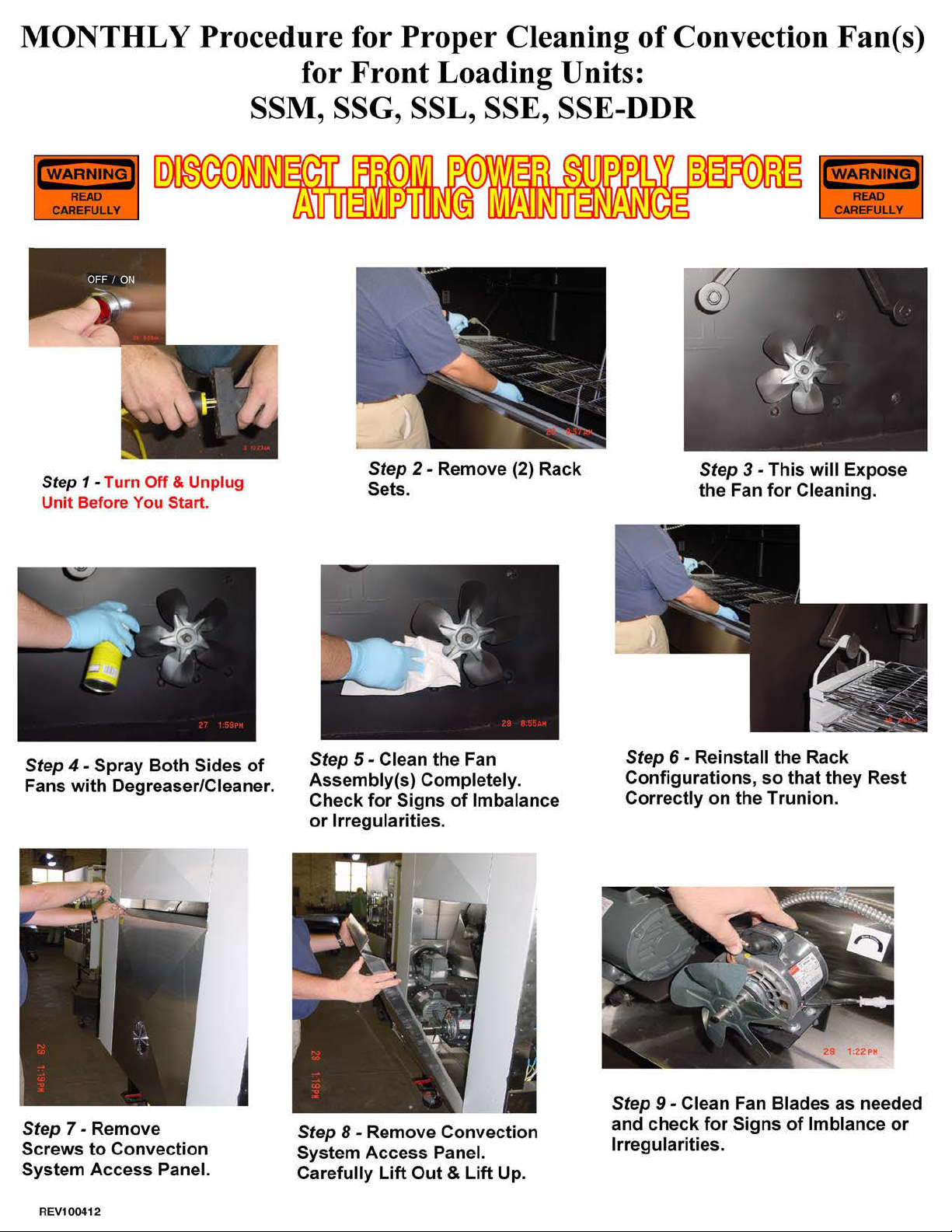
1.
2.
Clean Fans Blades (SHUT OFF POWER SUPPLY)
ONCE A MONTH - Maintenance Schedule
August
September
October
July
Clean Burner Tube (SHUT OFF GAS SUPPLY)
Once a month with gloved hand. DO NOT use hard objects
Burner Tube
April
May
June
Fan Blade
January
February
March
November
December
Insert Date for Monthly Cleaning

May
June
July
October
November
December
September
TWICE MONTHLY - Maintenance Schedule
Grease Bearings - 2 to 3 Squirts Bi-Monthly
March
April
January
February
Insert Date for Twice Monthly Cleaning
August

EVERY SIX MONTHS - Maintenance Schedule
Insert Date for Bi-Yearly Cleaning
PULLEY & FAN BLADES
Check every 6 months
CHECK SET SCREWS ON SPROCKETS,
First 6 Months
Second 6 Months
CLEAN FLUE PIPE
at least every 6 months
CHECK CHAIN TENSION & BELT TENSION
It should be tight, Check every 6 months

Every Six Months - Visual Inspection of Burner
DATE
DATE
DATE
DATE
DATE
DATE
DATE
DATE
DATE
Visual inspection daily during the first week of operation, then every six months thereafter. Look for
may result in the discribed conditions.
SHUT OFF BURNER
After Visual Inspection with a mirror - if ashes are built up inside burner - Remove burner and clean.
smoke backing out through the AIR SHUTTER on the BURNER FAN MOTOR or accumulation of a
BLACK TAR-LIKE substance around or above burner. A POSTIVE flow of air should be maintained
through the air shutter. If inspection indicates any of the above described conditions, IMMEDIATE
attention is required, to avoid a potential hazard. Contact the manufacturer immediately and
REVIEW your OWNERS/OPERATORS MANUAL for further instructions. NOTE: CHANGES in
building VENTILATION such as adding EXHAUST fans or DISCOUNTINUED use of MAKE-UP AIR

r
f
Cooking Capacity Chart
d
Model EL-IB & SSG
Rack Size: (15) 12" X 42" Cooking Surface: 52.5 Sq. Ft.
Item
Ribs (3 & Down) 15 4 45
Baby Back Ribs 15 6 75
Boston Butts (4-6 lbs) 10 5 40
Turkey (8 lbs) 10 3 30
Chicken (Whole) 10 5 50
(Half)
Brisket (12 lb.) 10 4 30
All item counts are estimate
15 9 120
Est. CapacityItem # Per Rack Rack Count
Cooking Time Chart
(Estimated at 225 degrees F)
Ribs (3 & Down)
Baby Back Ribs
Boston Butt
Pork Shoulder
Turkey
Chicken (Whole)
(Half)
Brisket
4 - 5
3 - 4
8 - 12
10 - 14
7 - 10
5 - 6
4 - 5 Hours
8 - 12 Hours
Hours
Hours
Hours
Hours
Hours
Hours
Above cooking times are approximate. Cooking time will vary depending on
product size, weight & beginning internal temperature. Refer to Internal
Temperature Chart below for doneness.
Meat Internal Temperature Chart
(Degrees Fahrenheit)
Pork Butt
Pork Shoulde
Beef Brisket
Bee
Poultry
Internal meat temperature should be taken with a meat thermometer, inserted
into the thickest portion of meat. Avoid touching bone or racks with probe as it
will affect correct temperature reading.
Rare
Medium Rare
Medium
Medium Well Done
Well Done
170 - 180
170 - 180
170 - 180
140
150
160
170
180
170 - 180

Notes:_______________________________________
_____________________________________________
_____________________________________________
_____________________________________________
_____________________________________________
_____________________________________________
_____________________________________________
_____________________________________________
_____________________________________________
_____________________________________________
_____________________________________________
_____________________________________________
_____________________________________________
_____________________________________________
_____________________________________________
_____________________________________________
_____________________________________________
_____________________________________________
_____________________________________________
_____________________________________________
_____________________________________________

 Loading...