

Ver. 1.0.0.1.
Operating Manual
PU-27
Control Panel
EN

2
Contents
1
Introduction
3
2
Warranty and liability
3
3
Safety
5 4 Purpose
5
5
Control panel description
5
6
Starting control panel operation
6 7 Main menu
7
8
Timers settings menu
8
9
Fast access to startup timers activation menu
9
10
Hydronic pre-heaters settings menu
10
11
Air heaters settings menu
12
12
Parameters settings menu
13
13
Time settings menu
14
14
Language settings menu
15
15
Software version display menu
15
16
Operation Time settings menu
16
17
Hydronic pre-heater start
16
18
Air heater start
19
Malfunctions
20
Acceptance and packing certificate

3
Introduction .
This Operating Manual is part of the documentation for hydronic pre-heaters and air
heaters (hereinafter referred as the product). The Manual contains information for the user
on safe maintenance of the product.
This control panel is compatible with the following products:
pre-heaters:
• 14ТС-10
• 14ТС-mini
• BINAR-5S
air heaters:
• Planar 2D
• Planar 4D
• Planar 44D
• Planar 8D
For detailed information on product models supported, please visit www.autoterm.ru
In case of any problems, we strongly recommend that you contact authorized service
centers, the addresses and phone numbers of which you can obtain from the seller or on the
www.autoterm.ru website.
Before operating the pre-heater, read this operating manual and the
pre-heater (heater) operating manual.
Warranty and liability .
The manufacturer will not be liable for defects and damage caused by failure to follow
the product installation and maintenance instructions.
• The control panel can only be used to control products from the list of compatible
products.
• Do not connect and disconnect the control panel connector while the product is
operating.
• After the product is switched off, it should not be switched on again for at least 5–10
seconds.
• For safe product operation, after two unsuccessful attempts to start the product in a
row, contact the service department for troubleshooting information.
• The warranty operating period of the control panel is 18 months from the date of sale,
provided the operation, transportation and storage rules are followed by the consumer.
• The warranty storage period is 24 months from the product packing date.
• In the absence of a company stamp indicating the sale date, the warranty period is
calculated from the date of manufacture.
This warranty does not cover defects appearing as a result of:
- force majeure circumstances, including lightning strike, fire, flood, impermissible
voltage surges or traffic accidents;

4
- failure to follow the rules for installation, operation, storage, and transportation
specified in the Operating Manual;
- use of the control panel for purposes other than intended.

5
Safety .
Do not switch on and operate the product in locations where combustible vapors
or gases or large amounts of dust can form and accumulate (for example, filling
stations or petroleum, fuel, coal, timber or grain storage facilities). Explosion hazard.
Do not switch on and operate the product in enclosed or non-ventilated premises.
Hazard of poisoning and asphyxiation by exhaust gases.
Do not switch on and operate the product if combustible materials or fluids are
present in the exhaust gas. Fire hazard.
Do not use a faulty product. Injury hazard due to use of faulty device.
Purpose .
The control panel is designed for:
• manual start and shutoff of the product;
• manual start and shutoff of the pump (for the pre-heater);
• manual start and shutoff of ventilation (for the heater);
• fluid temperature display (for the pre-heater)
• power supply voltage display;
• current time and operating time display;
• activation of the product startup timer;
• economy mode activation (for the pre-heater);
• additional heater operation mode selection (for the pre-heater);
• display of malfunction code in case of product malfunctions;
• display of control panel and control unit software version.
The control panel interface depends on the product it is connected to.
6
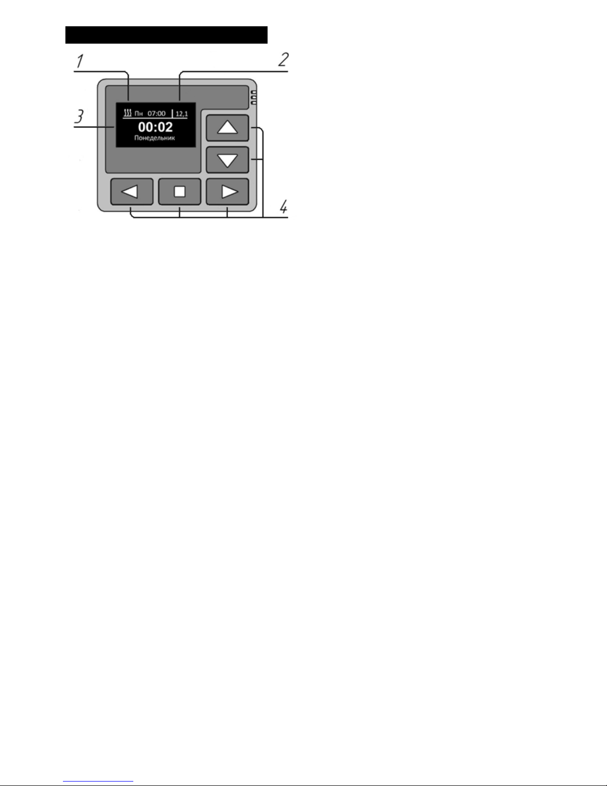
Control panel external view .
1 – activated startup timer.
2 - power supply voltage.
3 – LED indicator.
4 – control keys.
7
Starting control panel operation
After connecting the control panel to the product, the control panel software version and the process of
establishing connection with the product will be displayed.
After the connection is established, the main screen (current time, day of week and power supply voltage) will
be displayed.
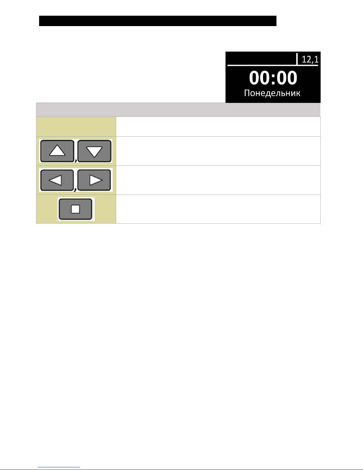
Main screen
Action of keys in the main screen:
Keys
Action
Navigation between the main screen and temperature sensors
screen.
Enter the main menu.
Start product.
8
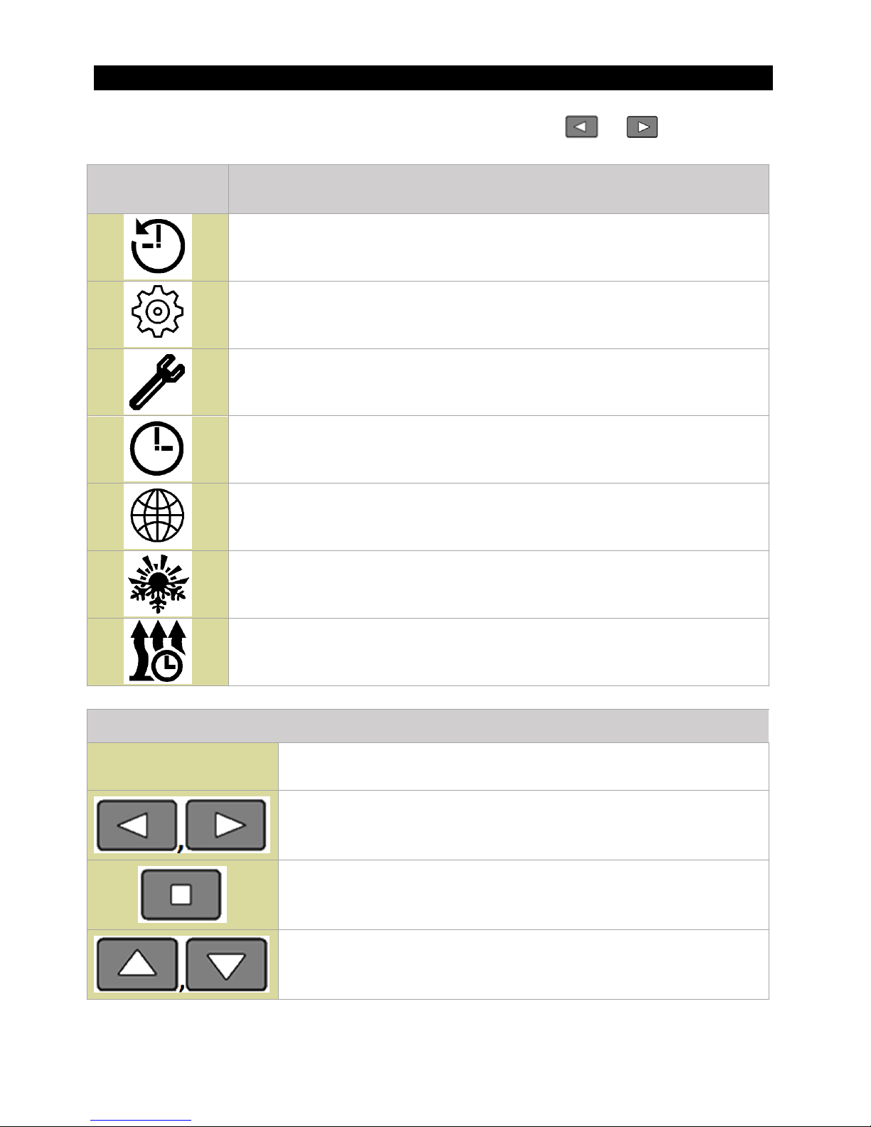
Main menu .
Switch to the main menu from the main screen by clicking the or key.
Menu icon
Description
Startup timers menu.
Product operating parameters setting menu.
(*this menu cannot be used for products without settings).
Control panel settings menu.
Current time and day settings menu.
Language settings menu.
Software version display menu.
Pre-heater operating time setting menu. (*this menu cannot be used
for air heaters).
Action of main menu keys:
Keys
Action
Navigation through the main menu
Activation of selected menu item
Exit from the main menu to the main screen

9
Timers settings menu
The control panel allows the startup timers to be programmed.
For startup timer setting, the following data must be
indicated:
• startup time in 24-hour format;
• day of week (Mon. - Sun.) or select daily startup
(Daily);
• activated timer:
- activated -
- non-activated -
Only a single timer can be activated. After editing of
the timers is completed, press the key to switch to
the main screen.
When the timer is activated, the activated timer icon,
day of week and startup time will appear in the upper
left corner of the main screen.
In case of product power loss, timer settings are saved and timer activation
is reset.
Action of the Timers menu keys:
Keys
Action
Navigation through the menu items
Change menu item value
Exit from this menu to the main screen

10
Fast access to startup timers activation menu .
For fast access to the timer activation menu from the control panel main screen, press
and hold the key.
This menu is only intended for timer activation.
Timers cannot be edited in this menu.
Action of timers activation menu keys:
Keys
Action
Navigation between timers.
Timer activation / deactivation.
Exit from this menu to the main screen
11
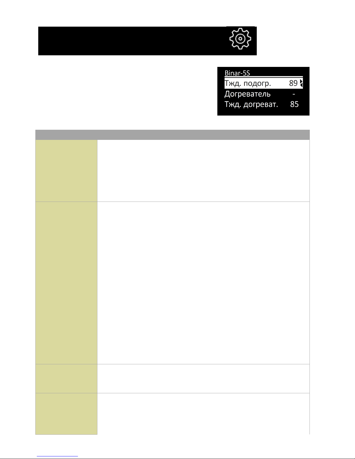
Hydronic pre-heaters settings menu .
BINAR-5S heater settings menu:
“Settings” menu items:
Pre-heater fluid
T
Fluid temperature at which the pre-heater switches to standby
mode (heater shuts off and pump continues to operate). When the
fluid temperature drops, the pre-heater exits standby mode (the
heater starts again). The default value for the switch to standby
mode is +88 °C. The temperature for the switch to standby mode
can be set in the +20 to +95 °С range.
Additional
heater
In the additional heater mode, the pre-heater operates with the
engine and maintains the set fluid temperature.
-
Additional heater mode is OFF.
А
Additional heater automatic operation. If the pre-heater is
off, after the vehicle engine starts, the pre-heater will start
automatically. After the engine stops, the pre-heater will
shut off automatically.
If the pre-heater is on, after the vehicle engine starts it will
switch to additional heater mode automatically.
Р
Additional heater manual operation. If the pre-heater is off,
after the vehicle engine starts, the pre-heater will not start
automatically (manual start is required). If the pre-heater is
on, after the vehicle engine starts it will switch to additional
heater mode automatically.
Additional
heater fluid T
Additional heater temperature setting. The required temperature
value can be set in the +75 to +95 °С range. The default
temperature is +85 °C.

12
Additional
heater pump
standby
Setting pump operation in standby mode. In the additional heater
mode, after the heater switches to standby mode, the pre-heater
shuts off and the pump continues to operate. Depending on this
setting:
-
The pump operates continuously (from the moment of start
to the moment of pre-heater shutoff).
✓
The pump operates simultaneously with the pre-heater and does
not operate in standby mode.
Heater
Setting of interior heater activation (provided the relay harness is
connected to the heater).
-
The interior heater is not activated while the pre-heater is on.
✓
While the pre-heater is on, the interior heater starts
automatically, depending on the fluid temperature.
Heater T
Setting of interior heater activation temperature. The required
temperature value can be set in the +30 to + 60 °С range. The
default temperature of relay activation is + 40 °C.
Pump with
engine
Setting of pump activation when the engine starts. The pump,
operating together with the heater, can be used for additional
circulation of coolant during vehicle engine operation. The pump
will activate automatically after the engine starts and will switch
off after engine shutoff.
-
The pump will not start.
✓
The pump will start when the engine starts.
Pump selection
Pump selection depending on configuration, pre-heater
-
Bosch pump
✓
ADVERS pump
Alarm channel
Setting of pre-heater control with the alarm channel. (provided the
pre-heater is connected to the alarm system and a free channel is
available).
-
Pre-heater control OFF
✓
Control ON.
Reset settings
Reset pre-heater settings to default values.
Action of Settings menu keys:
Keys
Action
Navigation through the menu items

13
Exit from menu to the main screen
Change menu item value
Air heaters settings menu .
Settings menu items:
Heater T based
In the “heater T based” mode, the “Set temperature” of the
temperature sensor located in the heater is used for operation.
Control panel T
based
In the “control panel T based” mode, the “Set temperature” of the
temperature sensor located in the control panel is used for
operation.
Exterior T based
In the “exterior T based” mode, the “Set temperature” of the
exterior temperature sensor is used for operation.
Power based
In the “Power based” mode, the “Set power” is used for
operation.
Set power
Heater power value in the 0 to 9 range, where 0 is minimum and
9 is maximum power.
Set temperature
The value at which the heater will switch to standby mode. The
heater will switch from standby mode when the temperature of
the sensor used to control heater operation drops 5 °C below the
“Set temperature” value.
Ventilation
Ventilation mode ON setting
-
Ventilation mode OFF. When the heater switches to
standby mode, the air pump will shut off.
✓
Ventilation mode ON. When the heater switches to standby
mode, the air pump will continue to operate in ventilation
mode.
Action of Settings menu keys:
Keys
Action

14
Navigation through the menu items
Exit from this menu to the main screen
Change menu item value
Parameters settings menu
This menu is intended for setting control panel
parameters.
Parameters menu items:
Dimming
Setting of indicator lighting time.
By default, the control panel indicator lighting time is 30
seconds. The light duration can be set in the 10 to 120 sec.
range with a 1 sec. step, or to set continuous lighting; in the
latter case, the “-“ sign will appear on the display.
During operation
Setting of indicator lighting during operation.
- the indicator is dimmed while the pre-heater is on.
✓ the indicator is constantly lit while the pre-heater is on.
Brightness
Setting of indicator light brightness. Indicator light brightness
is set in the 0 to 4 range. The brightness default value is 4.
Click start
Setting of start by clicking key for pre-heater/heater start.
-
Click – pump/ventilation start.
Press and hold – pre-heater start.
✓
Click – pre-heater start.
Press and hold – pump/ventilation start.
Clock adjustment
Setting clock adjustment. The clock accuracy may vary slightly
due to low temperatures. The required adjustment can be set in
the -59 to +59 seconds per day range. The correction default
time is 0.
15
Keys lighting
Keys lighting setting.
✓ - keys lighting ON.
- keys lighting OFF.
Action of Parameters menu keys:
Keys
Action
Navigation through the menu items
Change menu item value
Exit from this menu to the main screen
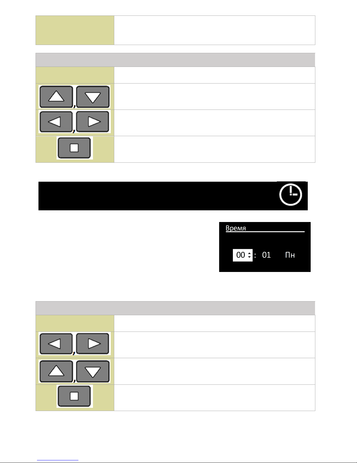
Time settings menu .
Current time is set and displayed in a 24-hour format.
When the control panel power is shut off, the current
time is set to zero and the day is reset to Monday.
Action of Time menu keys:
Keys
Action
Navigation through the menu items
Change menu item value
Save changes and exit from this menu to the main screen
16
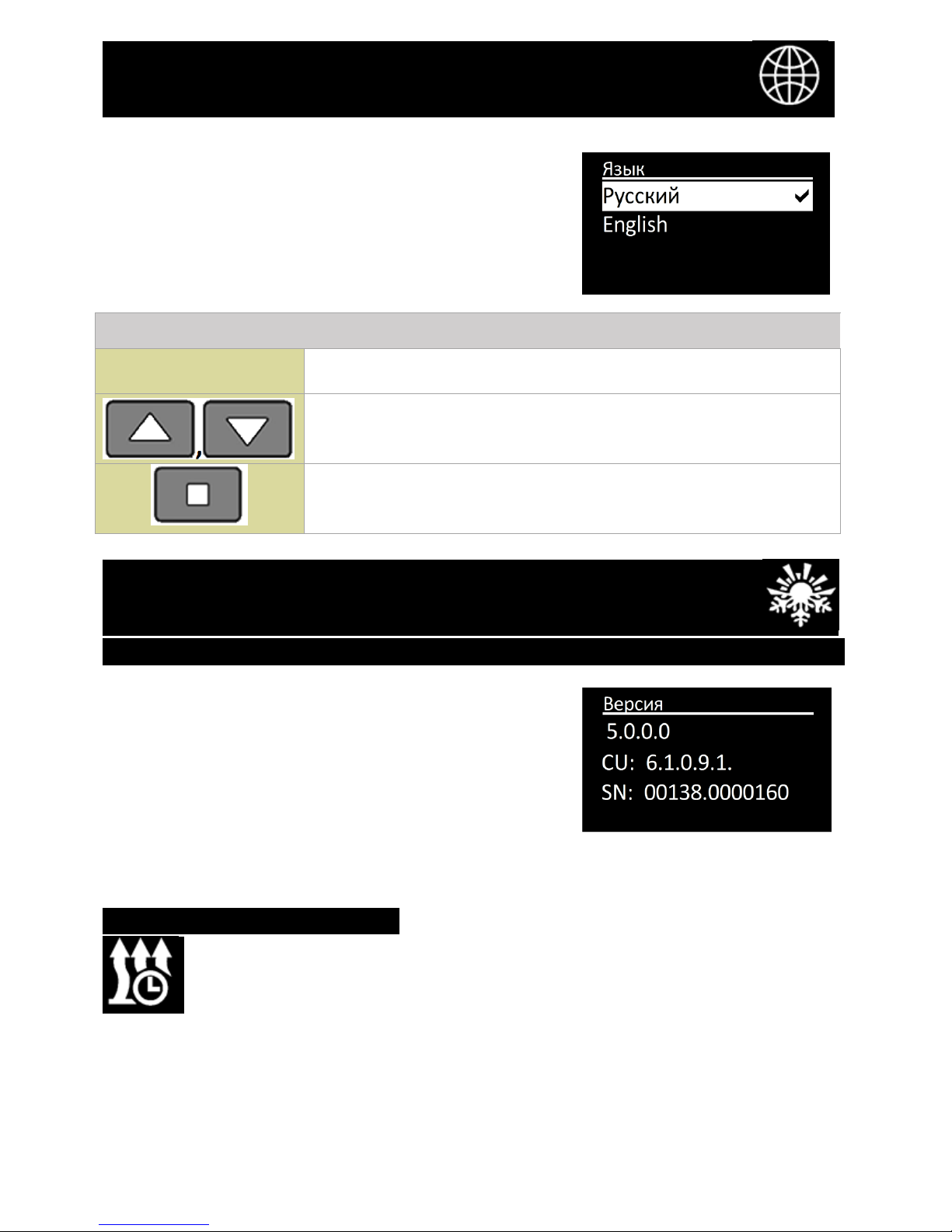
Language settings menu .
This menu is intended for interface language selection.
Action of Language menu keys:
Keys
Action
Navigation through the menu items
Confirmation of language selection and exit from this menu to
the main screen
Software version display menu
.
In this menu, the information on software versions is
displayed.
- control panel software version;
- product control unit software version;
- Product serial number.
Press any key to exit.
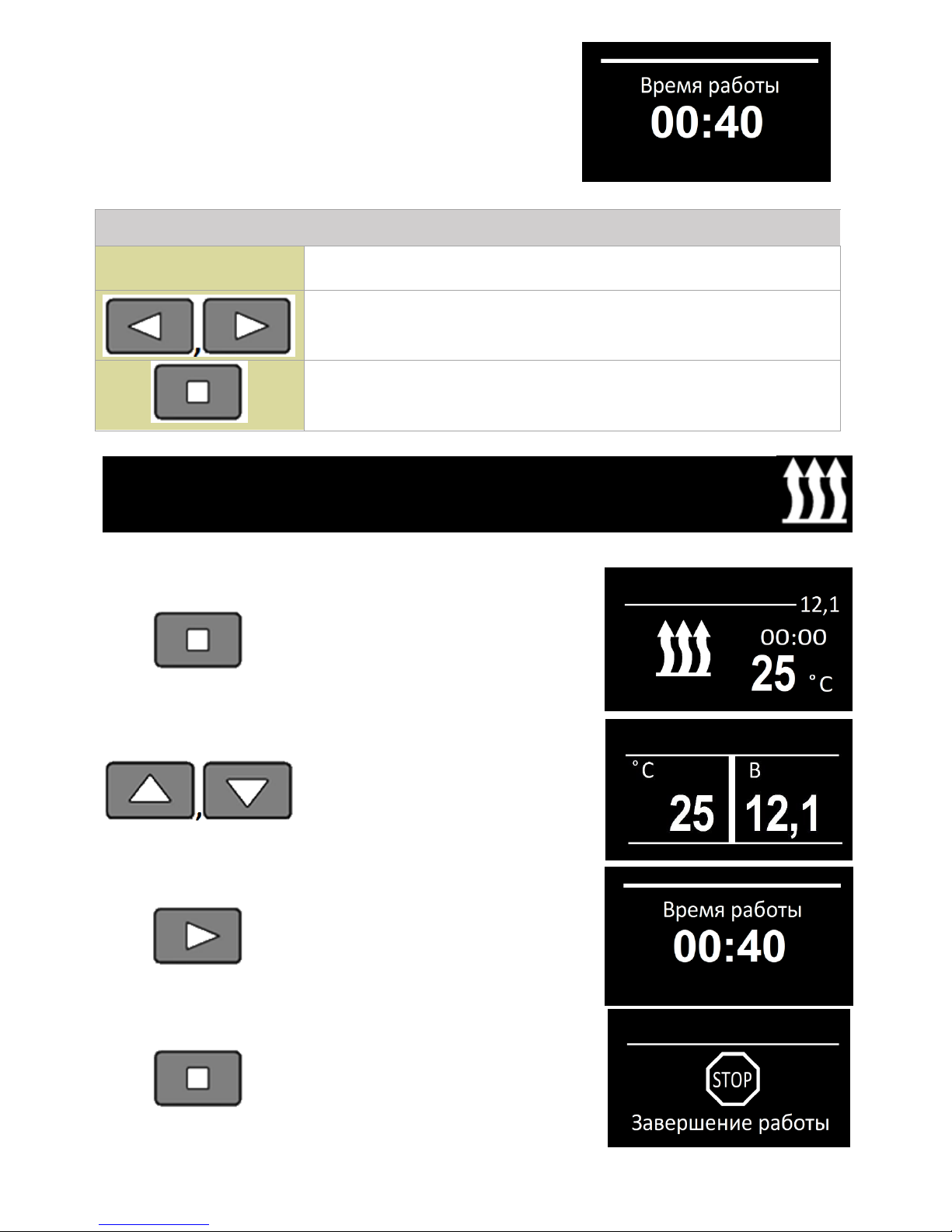
Operating Time settings menu
.
17
This menu is intended for setting pre-heater
operating time with a 5 minute step. The operating time
setting range depends on the product the control panel
is connected to.
Action of Operating Time menu keys:
Keys
Action
Value editing.
Confirmation of set value and exit from this menu to the main
screen
Hydronic pre-heater start
Start of pre-heater from the main
screen or from the temperature
sensors screen. The indicator will
appear as follows. The pre-heater
operating time count will be
started.
Full-screen display of current
coolant temperature and power
supply voltage.
When the pre-heater is operating,
enter the pre-heater operating
time editing menu.
Pre-heater shutoff.
18
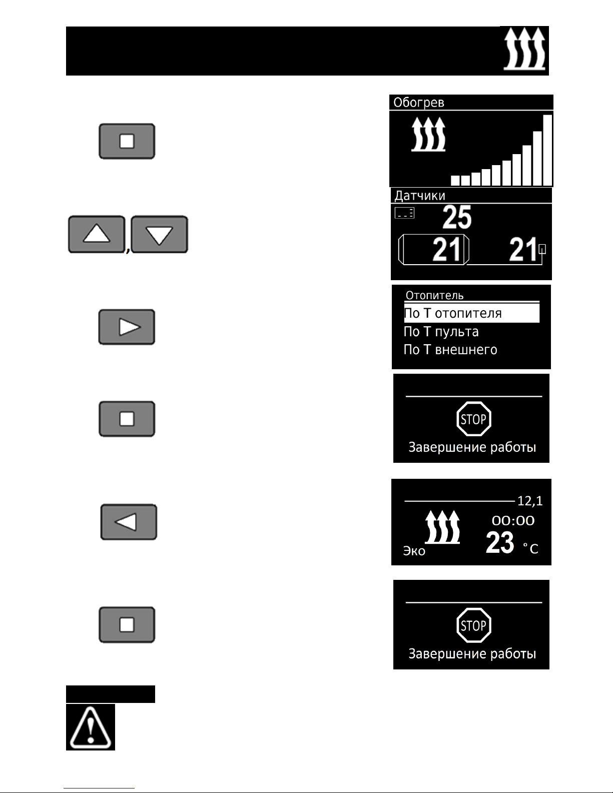
Air heater start
Start of heater from the main
screen or from the temperature
sensors screen. The indicator will
appear as follows.
Temperature sensors display.
When the pre-heater is operating,
enter the pre-heater operating
time editing menu.
Heater shutoff.
Economy mode ON / OFF.
(for 14ТС-mini and 14ТС-10)
Pre-heater shutoff.
Malfunctions

19
Malfunctions occurring during pre-heater operation
are coded and automatically displayed on the control
panel display. For malfunction reset, press any key. The
malfunction codes depend on the product the control
panel is connected to. See malfunction code descriptions
in the product operating manual.
ATTENTION!
Maintenance and repair should only be performed by trained, qualified
personnel!

20
Acceptance and packing certificate .
PU-27 control panel, serial number _________________
Is manufactured and accepted in accordance with the applicable technical documentation
and found suitable for operation.
Packing performed _____________________ _____________
Surname signature
Production date________________________ Stamp Here QC
Department

21
Notes
 Loading...