

Page 1
Canoe Anchor Kit
Installation
Instruction
Please read kit instructions carefully prior to installation.
Many of our kit installations can be viewed at www.youtube.com/oldtowncanoeandkayak
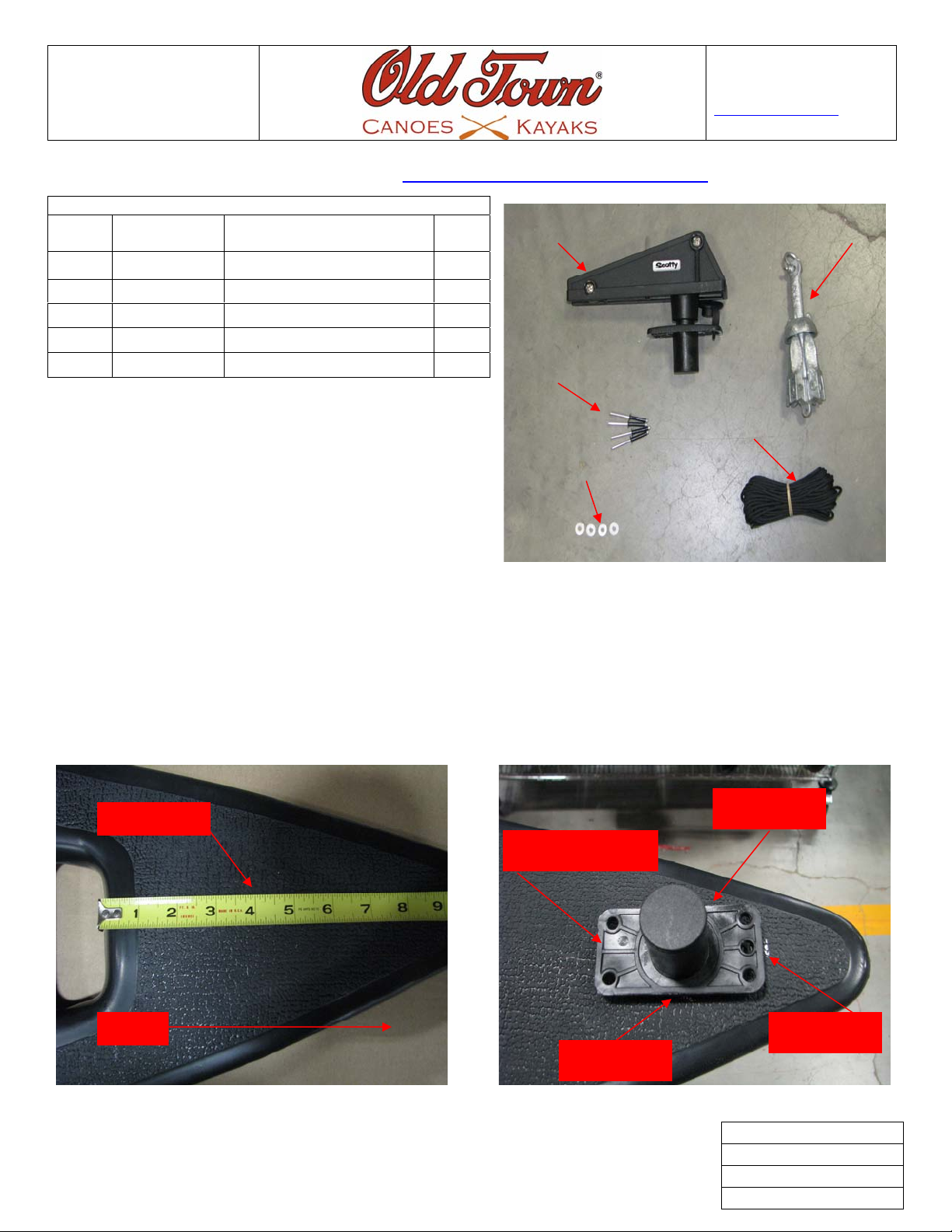
KIT CONTENTS
Ref.
Letter
A 01.1332.2714 Anchor Lock Flush Mount 1EA
B 01.1332.2709 Anchor 1.5 LB Folding 1EA
C 01.1315.1564 Rivets-AA611D BLK 4EA
D 01.1315.1568 Washer-Backup Deck 3/16” 4EA
E 01.1315.0455 Rope-Black Nylon 3MM 30FT
Part Number Description Qty
A B
C
D
125 Gilman Falls Road
Building B
Old Town, ME 04468 USA
800-8-KAYAKS
www.oldtowncanoe.com
E
Before getting started we recommend sorting out and separating the parts for easy access during assembly.
Tools Required: Drill, 13/64”Drill Bit, Pop Rivet Tool, 1 3/8” Hole Saw, Marking pencil,
and Tape measure.
1. Locate the base attached to the Anchor Lock Flush Mount (A) use it as a jig to mark the hole for the base on
the bow deck of the boat. Measure four inches toward the bow from the handle opening as shown in Fig# 1,
then on the four inch mark center the Anchor Lock base (A) upside down and mark all four sides as shown in
Fig# 2.
Mark Here
Mark Here
Four Inch Mark
Bow
Fig# 1 Fig# 2
Mark Here
Mark Here
Rev.Original
Issue Date: 11/29/2010
Doc. # K-01.1331.2028
Page 1 of 4
Page 2
Canoe Anchor Kit
Installation
Instruction
125 Gilman Falls Road
Building B
Old Town, ME 04468 USA
800-8-KAYAKS
www.oldtowncanoe.com
Please read kit instructions carefully prior to installation.
Many of our kit installations can be viewed at www.youtube.com/oldtowncanoeandkayak
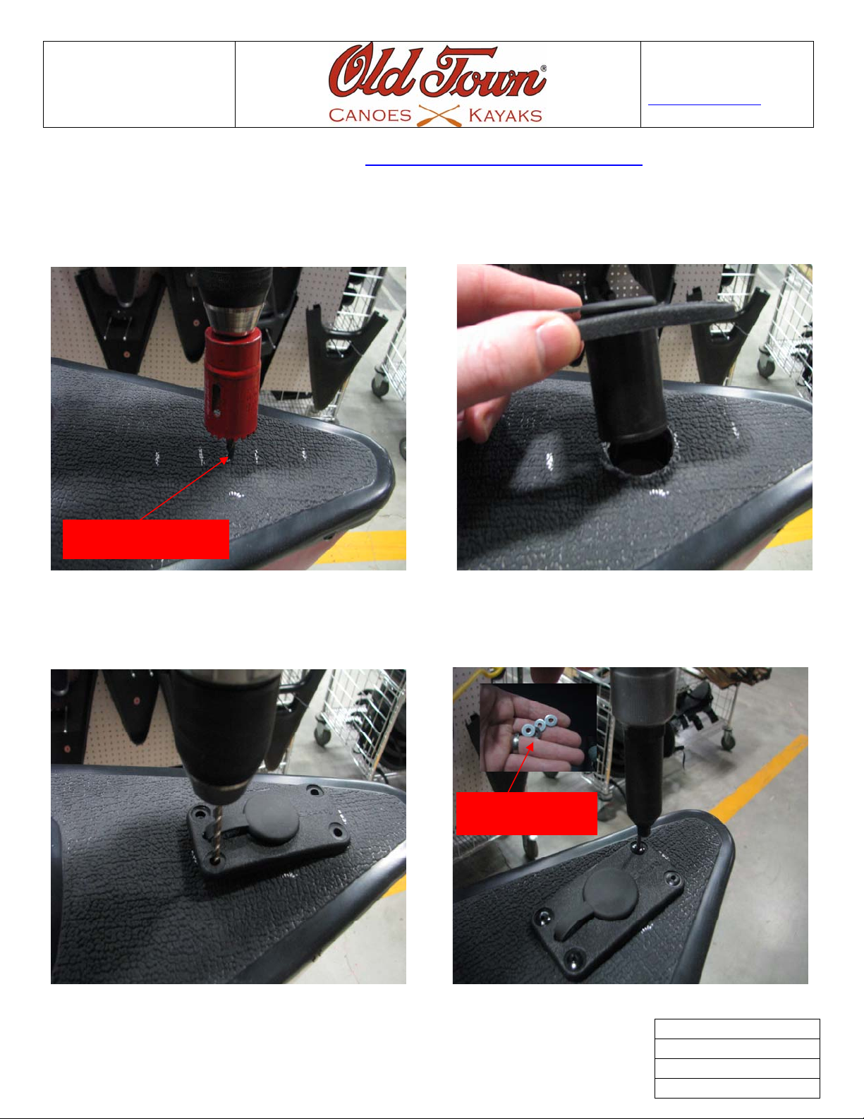
2. Find the center of the four marks you made in Fig# 2 and mark it, this is were you will need to drill your hole
with the hole saw as shown in Fig# 3. Insert the Anchor Lock Flush Mount (A) into the hole you drilled as
shown in Fig# 4
Drill on Center Mark
Fig# 3 Fig# 4
3. Now use your 13/64”drill bit to drill the four holes for the AA611D Rivets (C) as shown in Fig# 5. Insert the
AA611D rivets (C) into the holes you drilled and then pop the rivets with a pop rivet tool making sure to add
backup washers (D) to the under side of each rivet as shown in Fig# 6.
Backup Washers
Fig# 5 Fig# 6
Rev.Original
Issue Date: 11/29/2010
Doc. # K-01.1331.2028
Page 2 of 4
Page 3
Canoe Anchor Kit
Installation
Instruction
125 Gilman Falls Road
Building B
Old Town, ME 04468 USA
800-8-KAYAKS
www.oldtowncanoe.com
Please read kit instructions carefully prior to installation.
Many of our kit installations can be viewed at www.youtube.com/oldtowncanoeandkayak
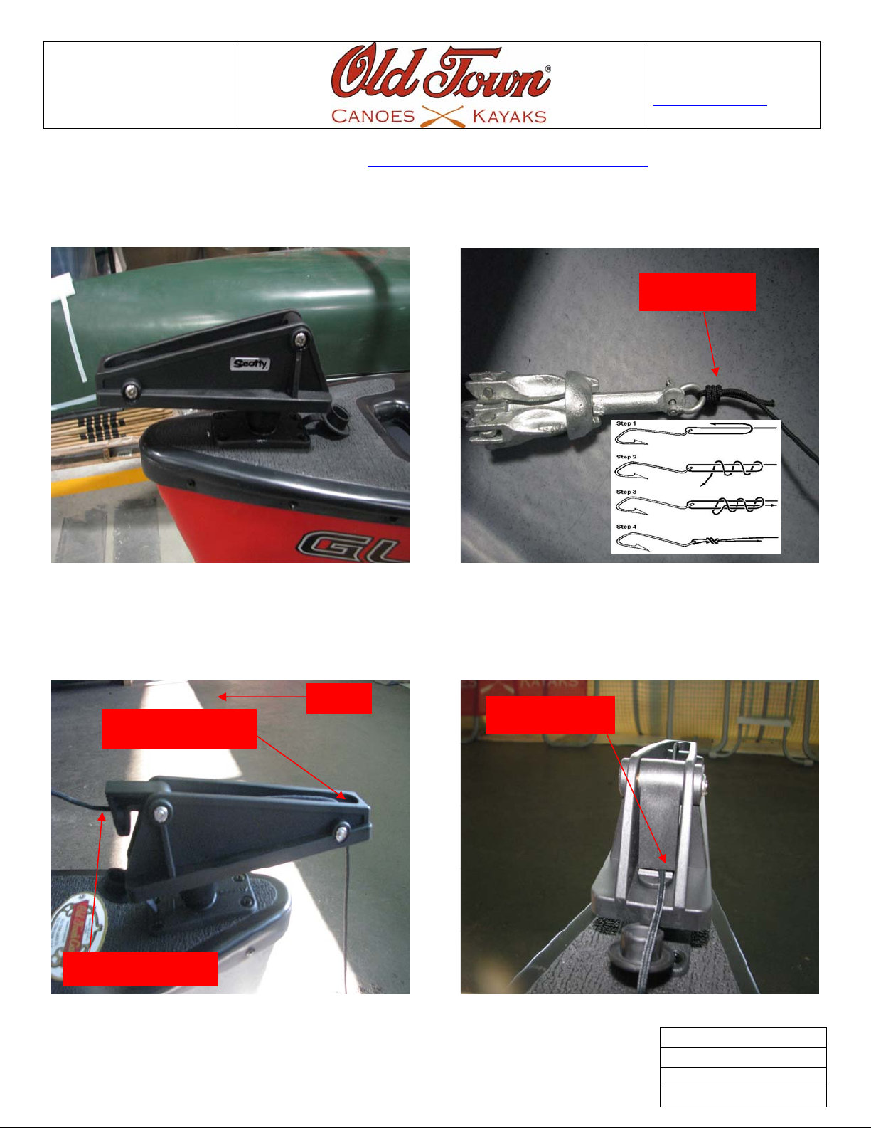
4. Insert the Anchor Lock Flush Mount (A) into its base as shown in Fig# 7. Now using a barrel Knot attach the
anchor rope (E) to the anchor (B) as shown in Fig# 8.
Barrel Knot
Fig# 7 Fig# 8
5. Feed the end of the anchor rope (E) threw the bottom of the Anchor Lock Flush Mount (A) up and over the
roller toward the stern of the boat then threw the rope lock as shown in Fig#9. To lock the rope ease the rope
forward and the rope lock will go down and lock the rope lock as shown in Fig# 10. Also tie a stopper knot in
the free end of the rope so it can not pull all the way threw the rope lock if it slips free.
Stern
Rope Lock On
Up and over roller
Threw Rope Lock
Fig# 9 Fig# 10
Rev.Original
Issue Date: 11/29/2010
Doc. # K-01.1331.2028
Page 3 of 4
 Loading...