

Page 1

oldsmobile :: Oldsmobile Cutlass Supreme V6-3100
3.1L MFI VIN M (1994)
Page 2

> Relays and Modules > Relays and Modules - Accessories and Optional Equipment > Alarm Module, (Vehicle Antitheft) > Component Information > Locations > Component Locations
Alarm Module: Component Locations
THEFT DETERRENT MODULE
The Theft Deterrent Module is located below the LH side of Instrument Panel , left of steering column.(I/P)
Page 3

Page 4

> Relays and Modules > Relays and Modules - Accessories and Optional Equipment > Alarm Module, (Vehicle Antitheft) > Component Information > Locations > Component Locations > Page 8
Steering Column
Page 5

Page 6

> Relays and Modules > Relays and Modules - Accessories and Optional Equipment > Alarm Module, (Vehicle Antitheft) > Component Information > Diagrams > Diagram Information and Instructions
Alarm Module: Diagram Information and Instructions
Cell References
CELL REFERENCES
"CELL"
General Motors vehicles often use references in their electrical wiring diagrams. These references are used in the Original EquipmentManual to refer to a section in the manual and not a specific diagram(s).
GM Sample Diagram W/ Cell Reference
For instance, in the diagram illustrated "Cell 20" is not a reference to another diagram but a reference to "Section 20" in the OE manual. In theexample, "Section 20" is the engine control section of the manual.
Diagrams / Electrical Diagrams
To navigate through these "Cell" references start at the vehicle level and go to: - for a complete list of the diagramsavailable for the vehicle. Choose the you are working on and view those diagrams. system
Note:
If unsure of the system - try utilizing the search feature. Type a component in the search feature that belongs to the system and when theresults are displayed note the path displayed. This will show the system the component belongs in.
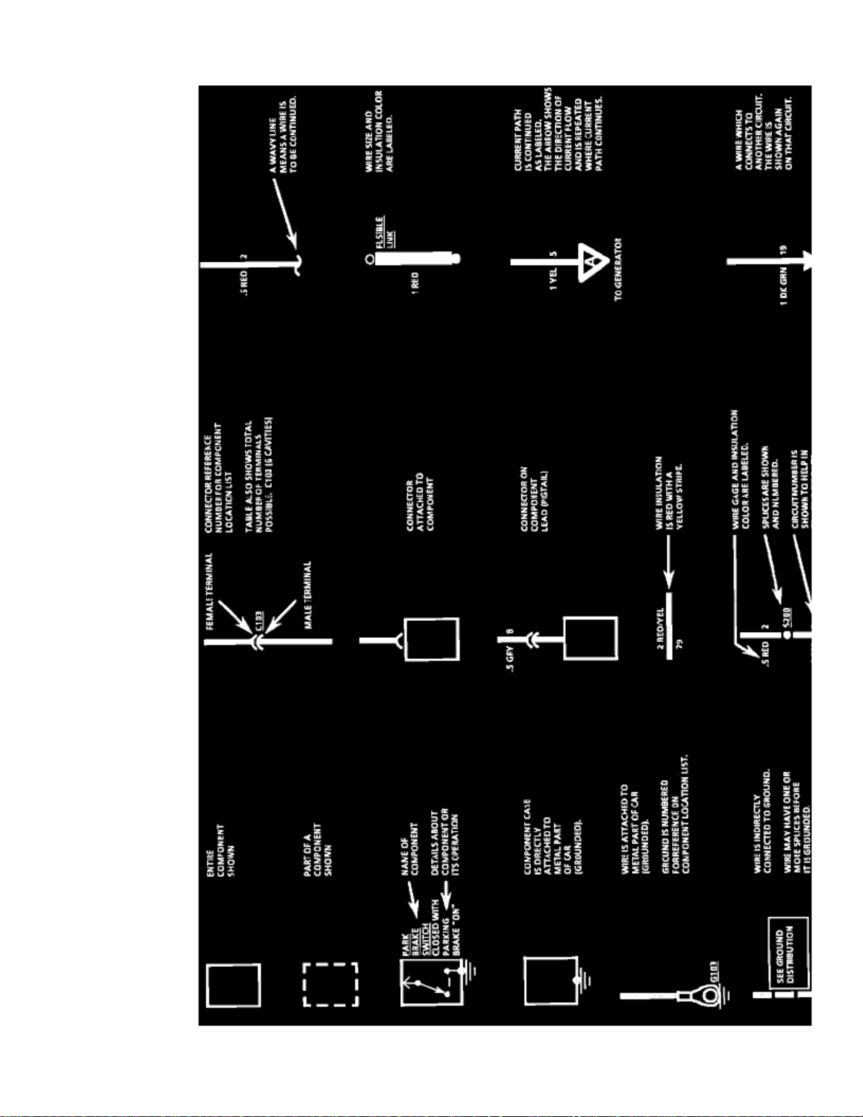
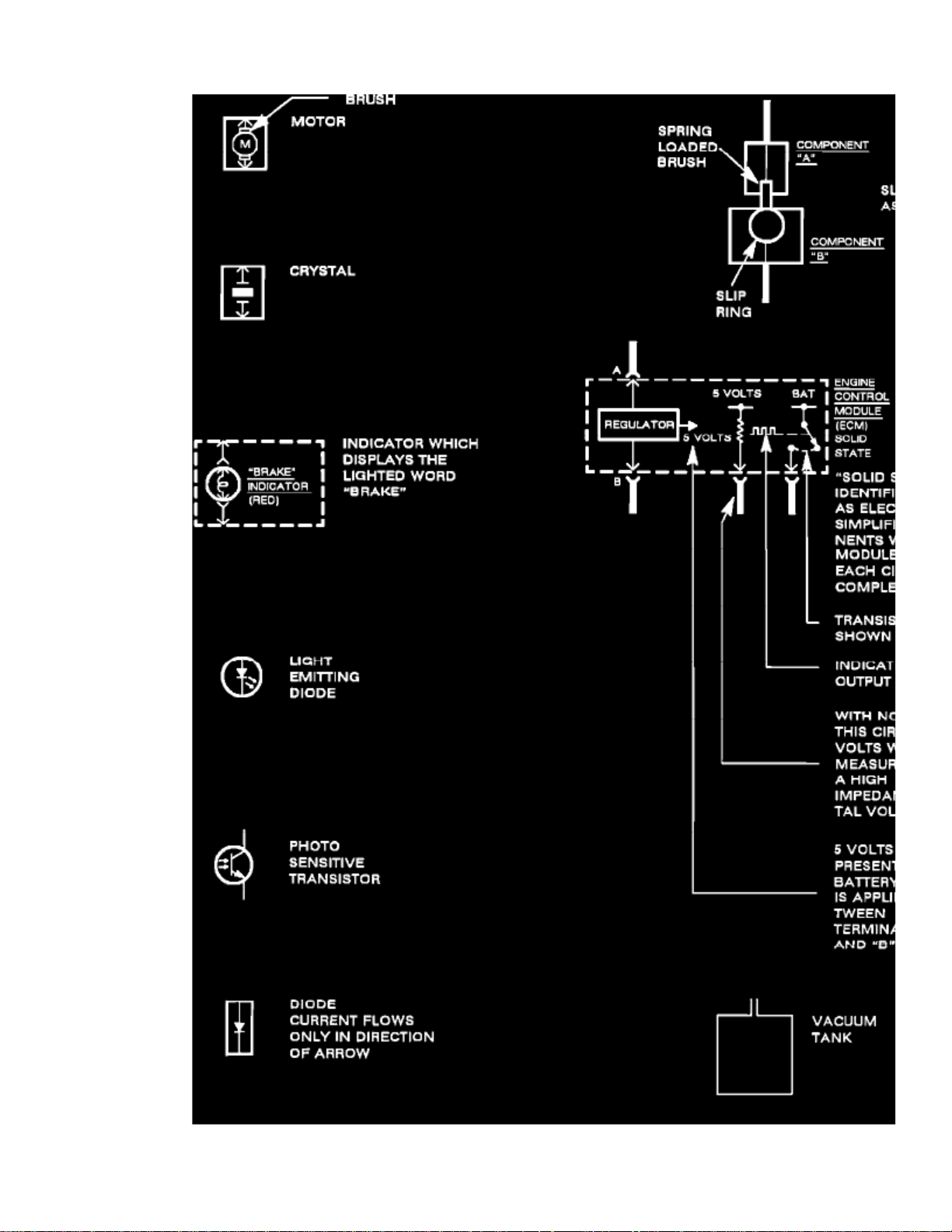
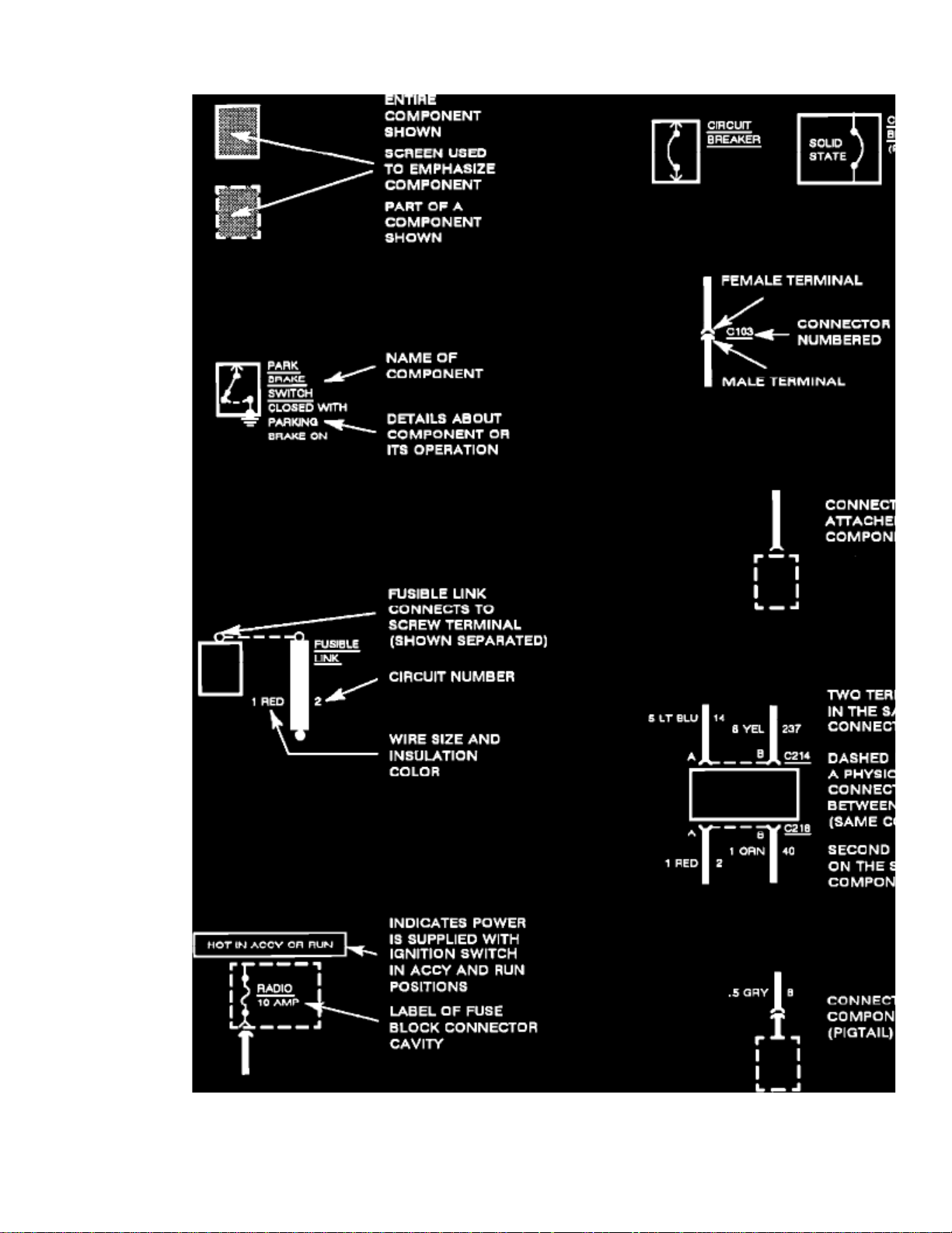
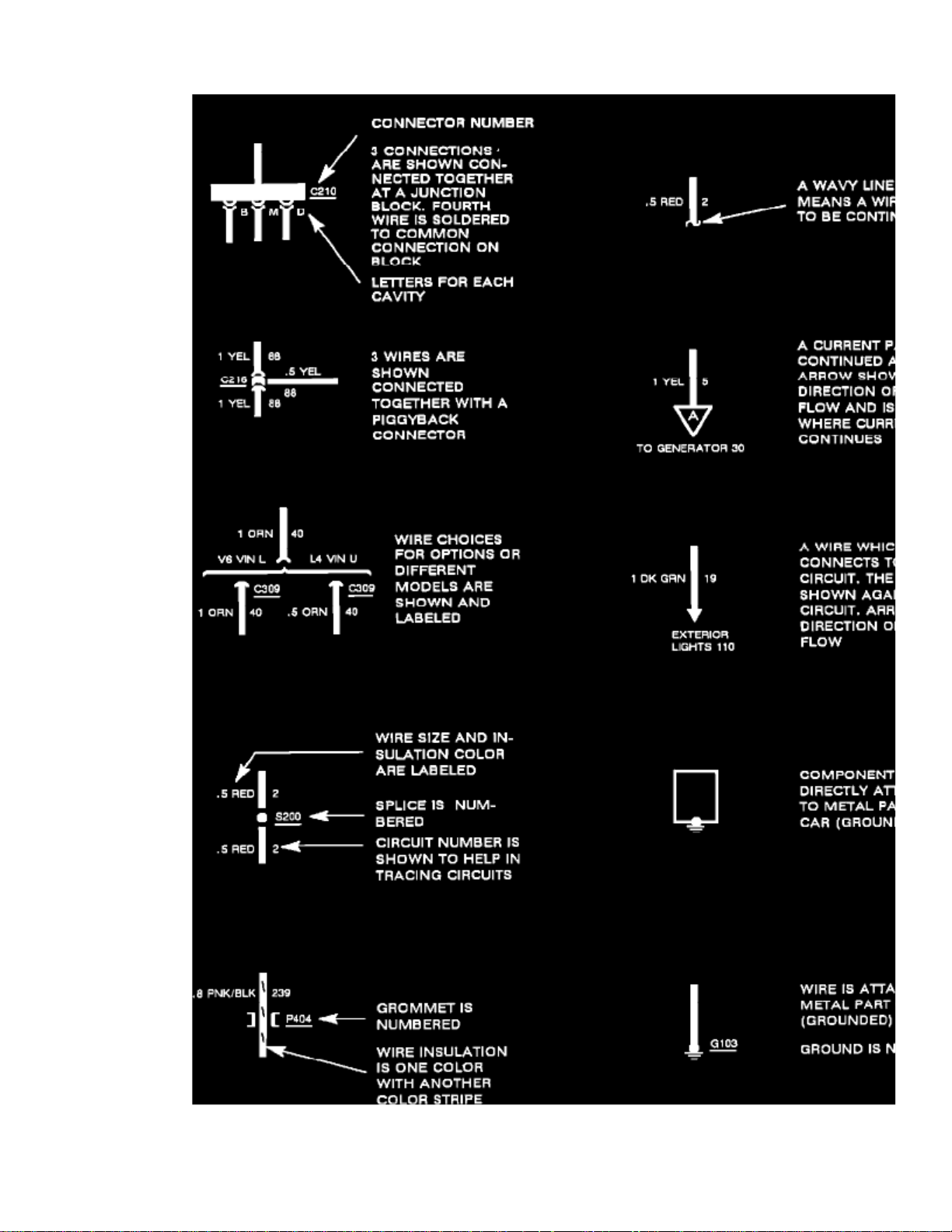
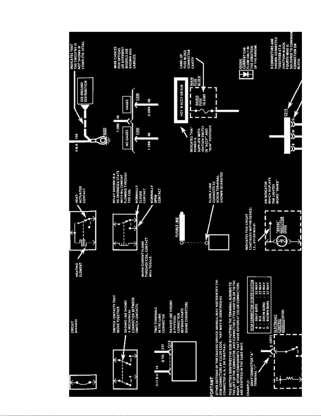
Schematic Symbols
Page 7

> Relays and Modules > Relays and Modules - Accessories and Optional Equipment > Alarm Module, (Vehicle Antitheft) > Component Information > Diagrams > Diagram
Information and Instructions > Page 11
Cutlass Supreme V6-3100 3.1L MFI VIN M (1994)
Page 8

Page 9

> Relays and Modules > Relays and Modules - Accessories and Optional Equipment > Alarm Module, (Vehicle Antitheft) > Component Information > Diagrams > Diagram
Information and Instructions > Page 12
Cutlass Supreme V6-3100 3.1L MFI VIN M (1994)
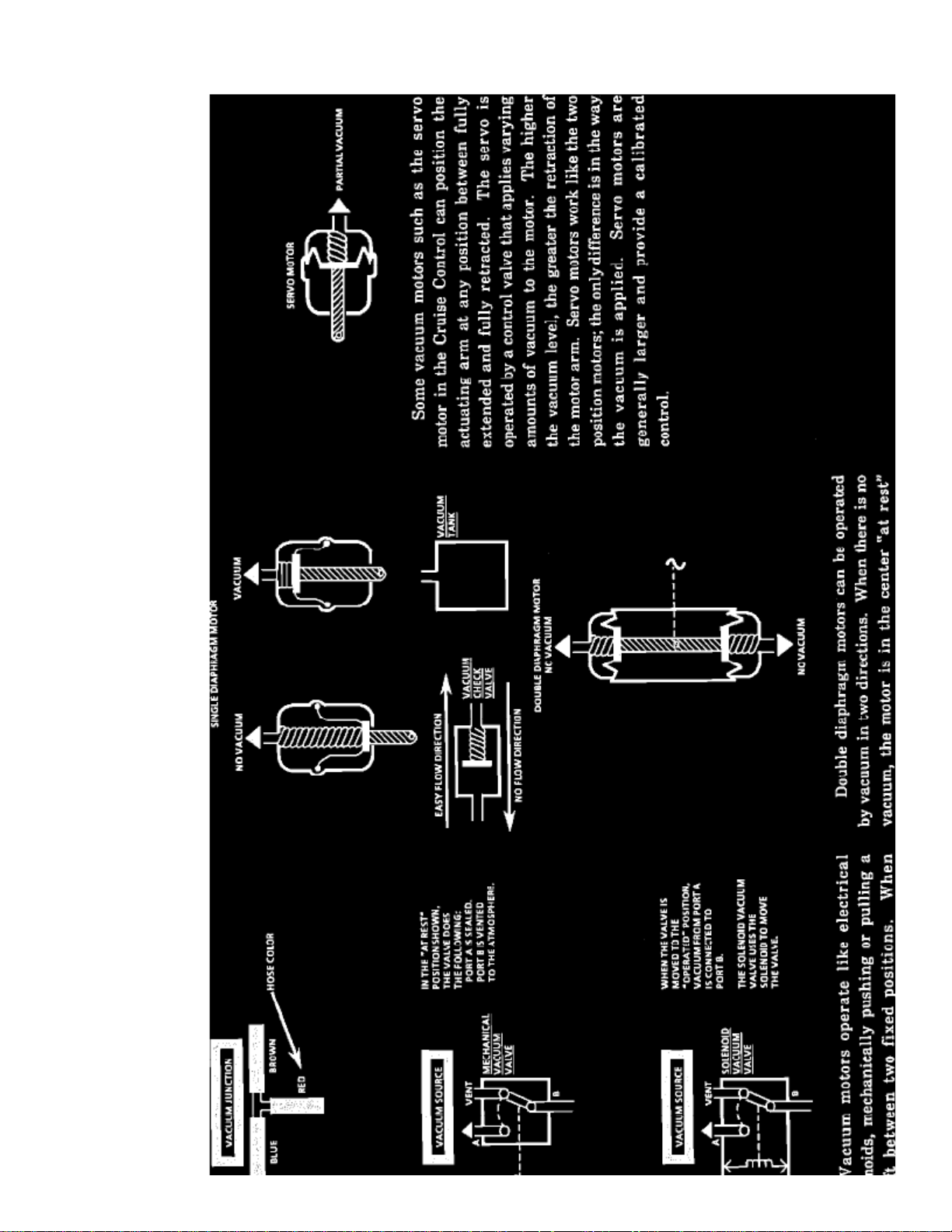
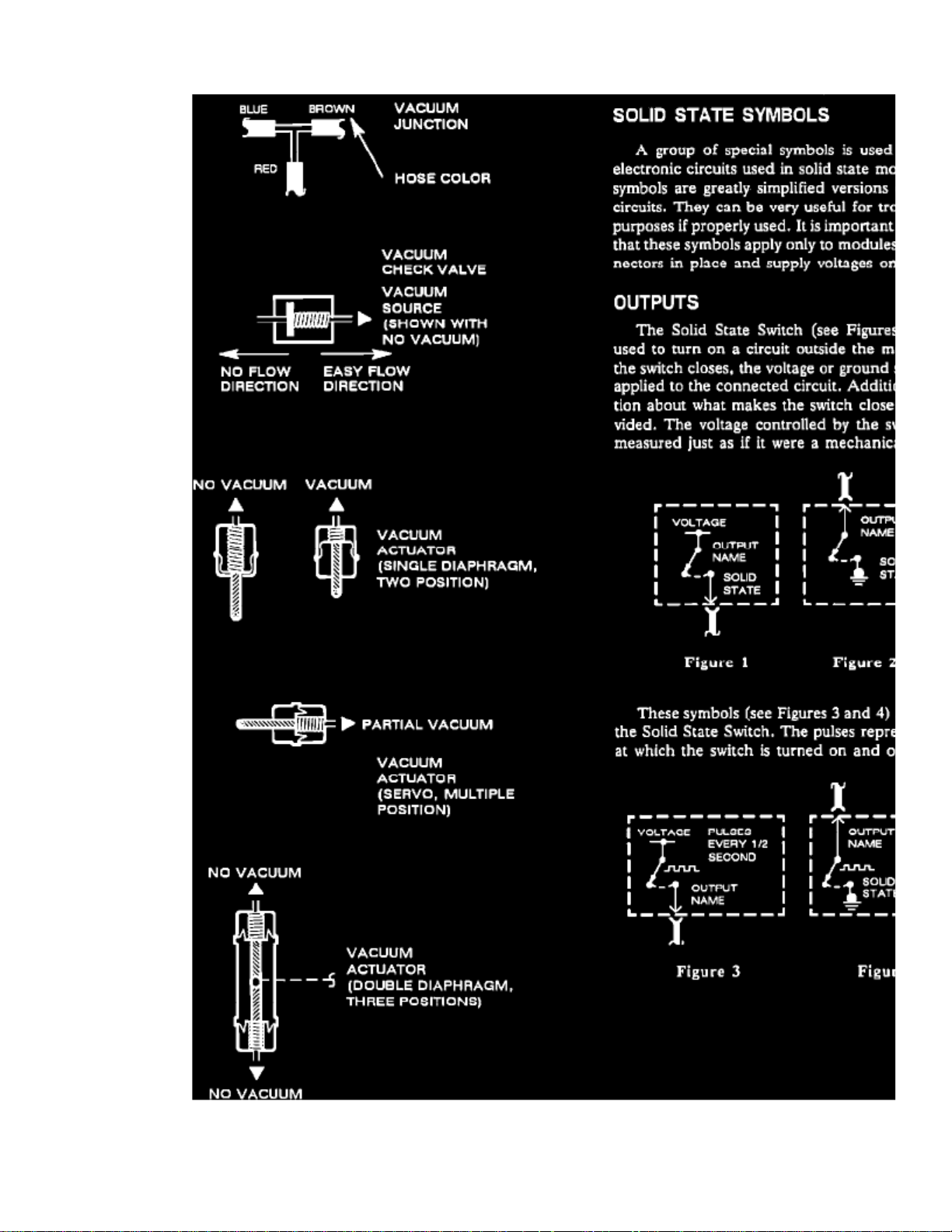
Symbols
Page 10
Page 11

> Relays and Modules > Relays and Modules - Accessories and Optional Equipment > Alarm Module, (Vehicle Antitheft) > Component Information > Diagrams > Diagram
Information and Instructions > Page 13
Cutlass Supreme V6-3100 3.1L MFI VIN M (1994)
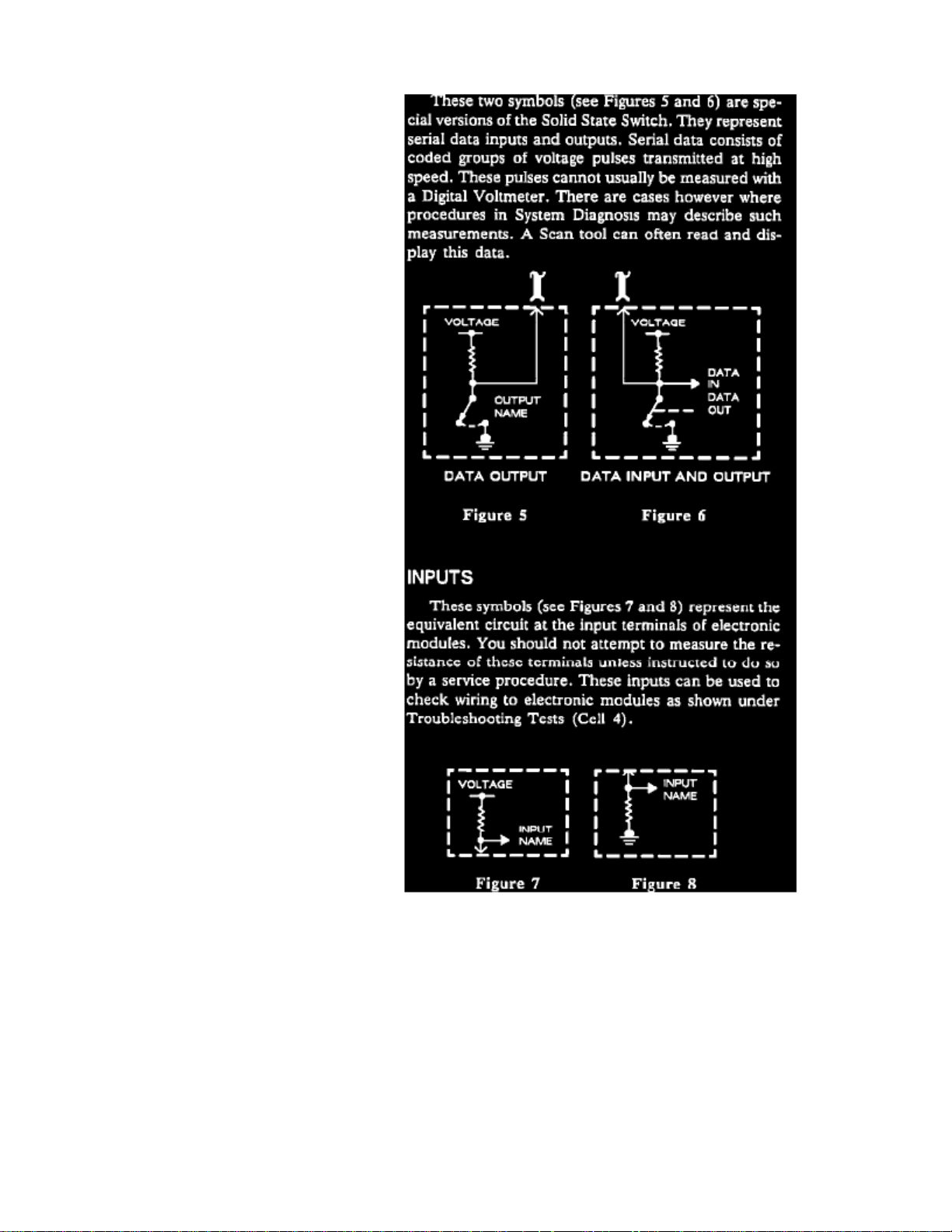
Symbols
Page 12
Page 13

> Relays and Modules > Relays and Modules - Accessories and Optional Equipment > Alarm Module, (Vehicle Antitheft) > Component Information > Diagrams > Diagram
Information and Instructions > Page 14
Cutlass Supreme V6-3100 3.1L MFI VIN M (1994)
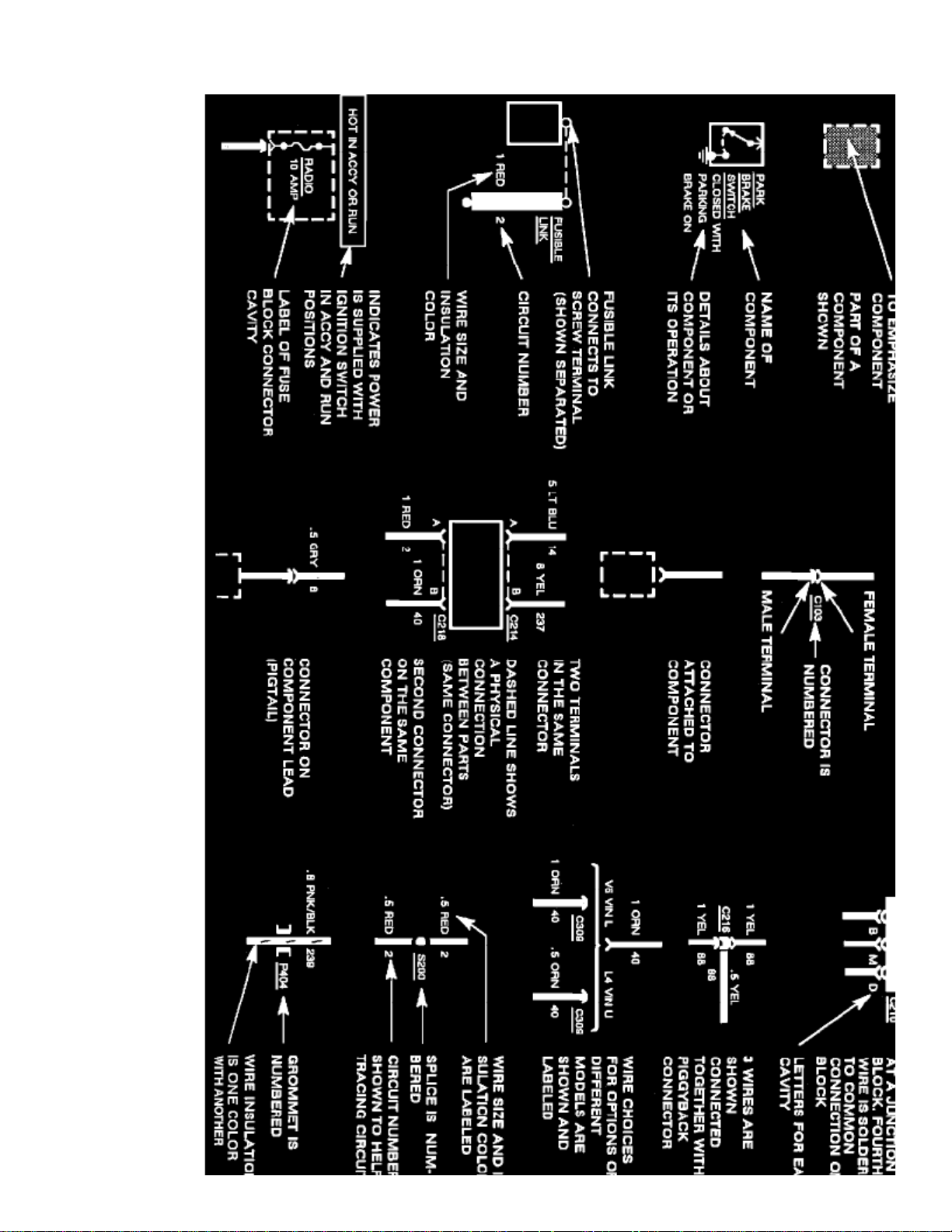
Symbols
Page 14
Page 15

> Relays and Modules > Relays and Modules - Accessories and Optional Equipment > Alarm Module, (Vehicle Antitheft) > Component Information > Diagrams > Diagram
Information and Instructions > Page 15
Cutlass Supreme V6-3100 3.1L MFI VIN M (1994)
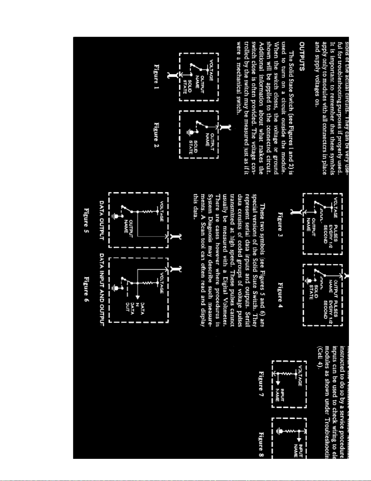
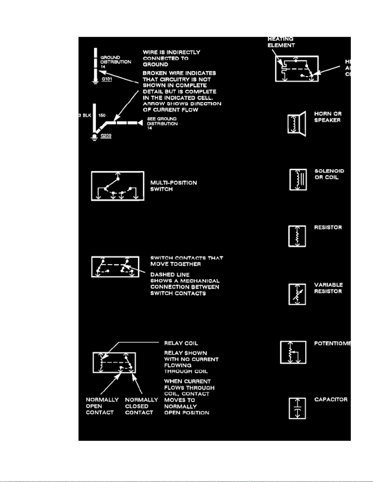
Schematic Symbols
Page 16

Page 17

> Relays and Modules > Relays and Modules - Accessories and Optional Equipment > Alarm Module, (Vehicle Antitheft) > Component Information > Diagrams > Diagram
Information and Instructions > Page 16
Cutlass Supreme V6-3100 3.1L MFI VIN M (1994)
Schematic Symbols
Page 18

Page 19

> Relays and Modules > Relays and Modules - Accessories and Optional Equipment > Alarm Module, (Vehicle Antitheft) > Component Information > Diagrams > Diagram
Information and Instructions > Page 17
Cutlass Supreme V6-3100 3.1L MFI VIN M (1994)
Schematic Symbols
Page 20
Page 21

> Relays and Modules > Relays and Modules - Accessories and Optional Equipment > Alarm Module, (Vehicle Antitheft) > Component Information > Diagrams > Diagram
Information and Instructions > Page 18
Cutlass Supreme V6-3100 3.1L MFI VIN M (1994)
Schematic Symbols
Page 22

Schematic Symbols
Page 23

> Relays and Modules > Relays and Modules - Accessories and Optional Equipment > Alarm Module, (Vehicle Antitheft) > Component Information > Diagrams > Diagram
Information and Instructions > Page 19
Cutlass Supreme V6-3100 3.1L MFI VIN M (1994)
Page 24

Schematic Symbols
Page 25

> Relays and Modules > Relays and Modules - Accessories and Optional Equipment > Alarm Module, (Vehicle Antitheft) > Component Information > Diagrams > Diagram
Information and Instructions > Page 20
Cutlass Supreme V6-3100 3.1L MFI VIN M (1994)
Page 26

Page 27

> Relays and Modules > Relays and Modules - Accessories and Optional Equipment > Alarm Module, (Vehicle Antitheft) > Component Information > Diagrams > Diagram
Information and Instructions > Page 21
Cutlass Supreme V6-3100 3.1L MFI VIN M (1994)
Schematic Symbols
Page 28
Page 29

> Relays and Modules > Relays and Modules - Accessories and Optional Equipment > Alarm Module, (Vehicle Antitheft) > Component Information > Diagrams > Diagram
Information and Instructions > Page 22
Cutlass Supreme V6-3100 3.1L MFI VIN M (1994)
Schematic Symbols
Page 30
Schematic Symbols
Page 31

> Relays and Modules > Relays and Modules - Accessories and Optional Equipment > Alarm Module, (Vehicle Antitheft) > Component Information > Diagrams > Diagram
Information and Instructions > Page 23
Cutlass Supreme V6-3100 3.1L MFI VIN M (1994)
Page 32
Schematic Symbols
Page 33

Page 34

> Relays and Modules > Relays and Modules - Accessories and Optional Equipment > Alarm Module, (Vehicle Antitheft) > Component Information > Diagrams > Diagram Information and Instructions > Page 24
Alarm Module: Diagnostic Aids
Pull-to-Seat Connectors
NOTE
: The following general repair procedures can be used to repair most types of connectors. Use the Pick(s) or Tools that apply to your terminal.Use Terminal repair kit J 38125 or equivalent.
Figure 20 - Typical Pull-To-Seat Connector
Follow the steps below to repair Pull-To-Seat connectors (Figure 20). The steps are illustrated with typical connectors. Your connector may be different,but the repair steps are similar. Some connectors DO NOT require all the steps shown. Skip the steps that DO NOT apply.
1.
Separate connector halves. Using the proper pick or removal tool, remove terminal (see Figures 21 & 22).a.
Pull lead gently.
b. Insert pick from front of connector into canal.
c. Pry tab up with tool.
d. Push lead to remove.
Figure 21
Page 35

> Relays and Modules > Relays and Modules - Accessories and Optional Equipment > Alarm Module, (Vehicle Antitheft) > Component Information > Diagrams > Diagram
Information and Instructions > Page 25
Cutlass Supreme V6-3100 3.1L MFI VIN M (1994)
Figure 22
2. If terminal is to be re-used, re-form locking tang.
3.
Make repair.a.
Pull terminal wire out of connector body.
b. Cut wire as close to terminal as possible.
c. Strip 5 mm (3/16") of insulation from the wire (see Figure 23).
d. Crimp new terminal to wire.
Page 36

e. Solder with rosin core solder.
f. Carefully pull on wire to draw terminal into connector body until it locks.
Push-to-Seat Connectors
NOTE
: The following general repair procedures can be used to repair most types of connectors. Use the Pick(s) or Tools that apply to your terminal.Use Terminal repair kit J38125 or equivalent.
Figure 1 - Typical Push-To-Seat Connector
Follow the steps below to repair Push-To-Seat connectors (Figure 1). The steps are illustrated with typical connectors. Your connector may be different,but the repair steps are similar. Some connectors Do Not require all the steps shown. Skip the steps that Do Not apply.
Remove Terminal Position Assurance (TPA) device, Connector Position Assurance (CPA) device and/or secondary lock.
1. Separate connector halves (see Figures 2 through 6).
Figure 2
Page 37

> Relays and Modules > Relays and Modules - Accessories and Optional Equipment > Alarm Module, (Vehicle Antitheft) > Component Information > Diagrams > Diagram
Information and Instructions > Page 26
Cutlass Supreme V6-3100 3.1L MFI VIN M (1994)
Figure 3
Page 38

Figure 4
Figure 5
Figure 6
2. Release terminal using proper pick or removal tool. Gently pull cable and terminal out the back of the connector (see Figures 7 through 11).
Page 39

> Relays and Modules > Relays and Modules - Accessories and Optional Equipment > Alarm Module, (Vehicle Antitheft) > Component Information > Diagrams > Diagram
Information and Instructions > Page 27
Cutlass Supreme V6-3100 3.1L MFI VIN M (1994)
Figure 7
Page 40

Figure 8
Figure 9
Figure 10
Page 41

> Relays and Modules > Relays and Modules - Accessories and Optional Equipment > Alarm Module, (Vehicle Antitheft) > Component Information > Diagrams > Diagram
Information and Instructions > Page 28
Cutlass Supreme V6-3100 3.1L MFI VIN M (1994)
Figure 11
3. If terminal is to be re-used, re-form locking tang (see Figures 12 through 16).
Page 42

Figure 12
Figure 13
Figure 14
Figure 15
Page 43

> Relays and Modules > Relays and Modules - Accessories and Optional Equipment > Alarm Module, (Vehicle Antitheft) > Component Information > Diagrams > Diagram
Information and Instructions > Page 29
Cutlass Supreme V6-3100 3.1L MFI VIN M (1994)
Figure 16
4. Make repair.
Page 44

When using a new terminal:a.
Slip cable seal away from terminal (if seal exist).
b. Cut wire as close to terminal as possible.
c. Slip a new cable seal onto wire (if necessary).
d. Strip 5mm (3/16") of insulation from wire.
e. Crimp a new terminal to the wire.
f. Solder with rosin core solder.
g. Slide cable seal toward terminal (if equipped with a seal).
h. Crimp cable seal and insulation (if equipped with a seal).
i. Apply grease to connectors outside the passenger compartment where the connector originally was equipped with grease.
Figure 17
To re-use a terminal or lead assembly, see previous steps c through i for repairs. Be sure to keep cable seal (if equipped) on terminal side of splice.
5. Insert lead from the back until it catches.
6. Install TPA's, CPA's and/or secondary locks, if equipped (see Figures 18 & 19).
Figure 18
Page 45

Figure 19
Page 46

> Relays and Modules > Relays and Modules - Accessories and Optional Equipment > Alarm Module, (Vehicle Antitheft) > Component Information > Diagrams > Diagram Information and Instructions > Page 30
Harness Connector Face
Page 47

Page 48

> Relays and Modules > Relays and Modules - Accessories and Optional Equipment > Alarm Module, (Vehicle Antitheft) > Component Information > Diagrams > Diagram Information and Instructions > Page 31
Alarm Module: Electrical Diagrams
Page 49

> Relays and Modules > Relays and Modules - Accessories and Optional Equipment > Alarm Module, (Vehicle Antitheft) > Component Information > Diagrams > Diagram
Information and Instructions > Page 32
Cutlass Supreme V6-3100 3.1L MFI VIN M (1994)
Theft Deterrent System - Part 1 of 2
Page 50

Page 51

Theft Deterrent System - Part 2 of 2
Page 52

> Relays and Modules > Relays and Modules - Accessories and Optional Equipment > Alarm Module, (Vehicle Antitheft) > Component Information > Diagrams > Page 33
Alarm Module: Service and Repair
PROGRAMMING A NEW DECODER MODULE
PASS-Key II Interrogator J35628
Key Code And Resistance Chart
New decoder modules are unprogrammed. Before the system will function properly after a new module has been installed, it must be programmed tothe code that matches the customer's keys. Programming a new module is very simple:
1. Install the new, unprogrammed decoder module.2. Insert one of the customer's keys in the ignition lock cylinder and turn it to the "ON" position. It's a good idea to start the engine at this time to
verify system operation.
3. Observe the "SECURITY" Indicator Lamp:
Page 53

The indicator lamp should light for about five seconds and then go out. If the wiring or contacts to the Key Resistance Pellet or the key isdefective or intermittent and a new module is installed, the Engine will start but the "SECURITY" Indicator will flash at a rate of one flash persecond until the Ignition Switch is turned off. This indicates that the module did not program and that the system components, wiring andcontacts should be checked for a fault.
IMPORTANT:
Before connecting the Interrogator to the ignition lock cylinder circuit, always verify, vehicle key code and set the code into theInterrogator using "key code" knob. This will prevent programming an unprogrammed decoder module with an undesired key code.
Page 54

> Relays and Modules > Relays and Modules - Accessories and Optional Equipment > Antenna Relay > Component Information > Locations
Component Locations
Page 55

Page 56

> Relays and Modules > Relays and Modules - Accessories and Optional Equipment > Antitheft Relay > Component Information > Locations
Antitheft Relay: Locations
THEFT DETERRENT RELAY
RH Side Of Passenger Compartment
The Theft Deterrent Relay is located below the RH side of Instrument Panel , near connector C200.(I/P)
Page 57

Page 58

> Relays and Modules > Relays and Modules - Accessories and Optional Equipment > Antitheft Relay > Component Information > Diagrams > Diagram Information and Instructions
Antitheft Relay: Diagram Information and Instructions
Cell References
CELL REFERENCES
"CELL"
General Motors vehicles often use references in their electrical wiring diagrams. These references are used in the Original EquipmentManual to refer to a section in the manual and not a specific diagram(s).
GM Sample Diagram W/ Cell Reference
For instance, in the diagram illustrated "Cell 20" is not a reference to another diagram but a reference to "Section 20" in the OE manual. In theexample, "Section 20" is the engine control section of the manual.
Diagrams / Electrical Diagrams
To navigate through these "Cell" references start at the vehicle level and go to: - for a complete list of the diagramsavailable for the vehicle. Choose the you are working on and view those diagrams. system
Note:
If unsure of the system - try utilizing the search feature. Type a component in the search feature that belongs to the system and when theresults are displayed note the path displayed. This will show the system the component belongs in.
Schematic Symbols
Page 59

> Relays and Modules > Relays and Modules - Accessories and Optional Equipment > Antitheft Relay > Component Information > Diagrams > Diagram Information and
Instructions > Page 42
Cutlass Supreme V6-3100 3.1L MFI VIN M (1994)
Page 60
Page 61

> Relays and Modules > Relays and Modules - Accessories and Optional Equipment > Antitheft Relay > Component Information > Diagrams > Diagram Information and
Instructions > Page 43
Cutlass Supreme V6-3100 3.1L MFI VIN M (1994)
Symbols
Page 62

Page 63

> Relays and Modules > Relays and Modules - Accessories and Optional Equipment > Antitheft Relay > Component Information > Diagrams > Diagram Information and
Instructions > Page 44
Cutlass Supreme V6-3100 3.1L MFI VIN M (1994)
Symbols
Page 64

Page 65

> Relays and Modules > Relays and Modules - Accessories and Optional Equipment > Antitheft Relay > Component Information > Diagrams > Diagram Information and
Instructions > Page 45
Cutlass Supreme V6-3100 3.1L MFI VIN M (1994)
Symbols
Page 66

Page 67

> Relays and Modules > Relays and Modules - Accessories and Optional Equipment > Antitheft Relay > Component Information > Diagrams > Diagram Information and
Instructions > Page 46
Cutlass Supreme V6-3100 3.1L MFI VIN M (1994)
Schematic Symbols
Page 68

Page 69

> Relays and Modules > Relays and Modules - Accessories and Optional Equipment > Antitheft Relay > Component Information > Diagrams > Diagram Information and
Instructions > Page 47
Cutlass Supreme V6-3100 3.1L MFI VIN M (1994)
Schematic Symbols
Page 70

Page 71

> Relays and Modules > Relays and Modules - Accessories and Optional Equipment > Antitheft Relay > Component Information > Diagrams > Diagram Information and
Instructions > Page 48
Cutlass Supreme V6-3100 3.1L MFI VIN M (1994)
Schematic Symbols
Page 72

Page 73

> Relays and Modules > Relays and Modules - Accessories and Optional Equipment > Antitheft Relay > Component Information > Diagrams > Diagram Information and
Instructions > Page 49
Cutlass Supreme V6-3100 3.1L MFI VIN M (1994)
Schematic Symbols
Page 74
Schematic Symbols
Page 75

> Relays and Modules > Relays and Modules - Accessories and Optional Equipment > Antitheft Relay > Component Information > Diagrams > Diagram Information and
Instructions > Page 50
Cutlass Supreme V6-3100 3.1L MFI VIN M (1994)
Page 76
Schematic Symbols
Page 77

> Relays and Modules > Relays and Modules - Accessories and Optional Equipment > Antitheft Relay > Component Information > Diagrams > Diagram Information and
Instructions > Page 51
Cutlass Supreme V6-3100 3.1L MFI VIN M (1994)
Page 78
Page 79

> Relays and Modules > Relays and Modules - Accessories and Optional Equipment > Antitheft Relay > Component Information > Diagrams > Diagram Information and
Instructions > Page 52
Cutlass Supreme V6-3100 3.1L MFI VIN M (1994)
Schematic Symbols
Page 80

Page 81

> Relays and Modules > Relays and Modules - Accessories and Optional Equipment > Antitheft Relay > Component Information > Diagrams > Diagram Information and
Instructions > Page 53
Cutlass Supreme V6-3100 3.1L MFI VIN M (1994)
Schematic Symbols
Page 82

Schematic Symbols
Page 83

> Relays and Modules > Relays and Modules - Accessories and Optional Equipment > Antitheft Relay > Component Information > Diagrams > Diagram Information and
Instructions > Page 54
Cutlass Supreme V6-3100 3.1L MFI VIN M (1994)
Page 84

Schematic Symbols
Page 85

Page 86

> Relays and Modules > Relays and Modules - Accessories and Optional Equipment > Antitheft Relay > Component Information > Diagrams > Diagram Information and Instructions > Page 55
Antitheft Relay: Diagnostic Aids
Pull-to-Seat Connectors
NOTE
: The following general repair procedures can be used to repair most types of connectors. Use the Pick(s) or Tools that apply to your terminal.Use Terminal repair kit J 38125 or equivalent.
Figure 20 - Typical Pull-To-Seat Connector
Follow the steps below to repair Pull-To-Seat connectors (Figure 20). The steps are illustrated with typical connectors. Your connector may be different,but the repair steps are similar. Some connectors DO NOT require all the steps shown. Skip the steps that DO NOT apply.
1.
Separate connector halves. Using the proper pick or removal tool, remove terminal (see Figures 21 & 22).a.
Pull lead gently.
b. Insert pick from front of connector into canal.
c. Pry tab up with tool.
d. Push lead to remove.
Figure 21
Page 87

> Relays and Modules > Relays and Modules - Accessories and Optional Equipment > Antitheft Relay > Component Information > Diagrams > Diagram Information and
Instructions > Page 56
Cutlass Supreme V6-3100 3.1L MFI VIN M (1994)
Figure 22
2. If terminal is to be re-used, re-form locking tang.
3.
Make repair.a.
Pull terminal wire out of connector body.
b. Cut wire as close to terminal as possible.
c. Strip 5 mm (3/16") of insulation from the wire (see Figure 23).
d. Crimp new terminal to wire.
Page 88

e. Solder with rosin core solder.
f. Carefully pull on wire to draw terminal into connector body until it locks.
Push-to-Seat Connectors
NOTE
: The following general repair procedures can be used to repair most types of connectors. Use the Pick(s) or Tools that apply to your terminal.Use Terminal repair kit J38125 or equivalent.
Figure 1 - Typical Push-To-Seat Connector
Follow the steps below to repair Push-To-Seat connectors (Figure 1). The steps are illustrated with typical connectors. Your connector may be different,but the repair steps are similar. Some connectors Do Not require all the steps shown. Skip the steps that Do Not apply.
Remove Terminal Position Assurance (TPA) device, Connector Position Assurance (CPA) device and/or secondary lock.
1. Separate connector halves (see Figures 2 through 6).
Figure 2
Page 89

> Relays and Modules > Relays and Modules - Accessories and Optional Equipment > Antitheft Relay > Component Information > Diagrams > Diagram Information and
Instructions > Page 57
Cutlass Supreme V6-3100 3.1L MFI VIN M (1994)
Figure 3
Page 90

Figure 4
Figure 5
Figure 6
2. Release terminal using proper pick or removal tool. Gently pull cable and terminal out the back of the connector (see Figures 7 through 11).
Page 91

> Relays and Modules > Relays and Modules - Accessories and Optional Equipment > Antitheft Relay > Component Information > Diagrams > Diagram Information and
Instructions > Page 58
Cutlass Supreme V6-3100 3.1L MFI VIN M (1994)
Figure 7
Page 92
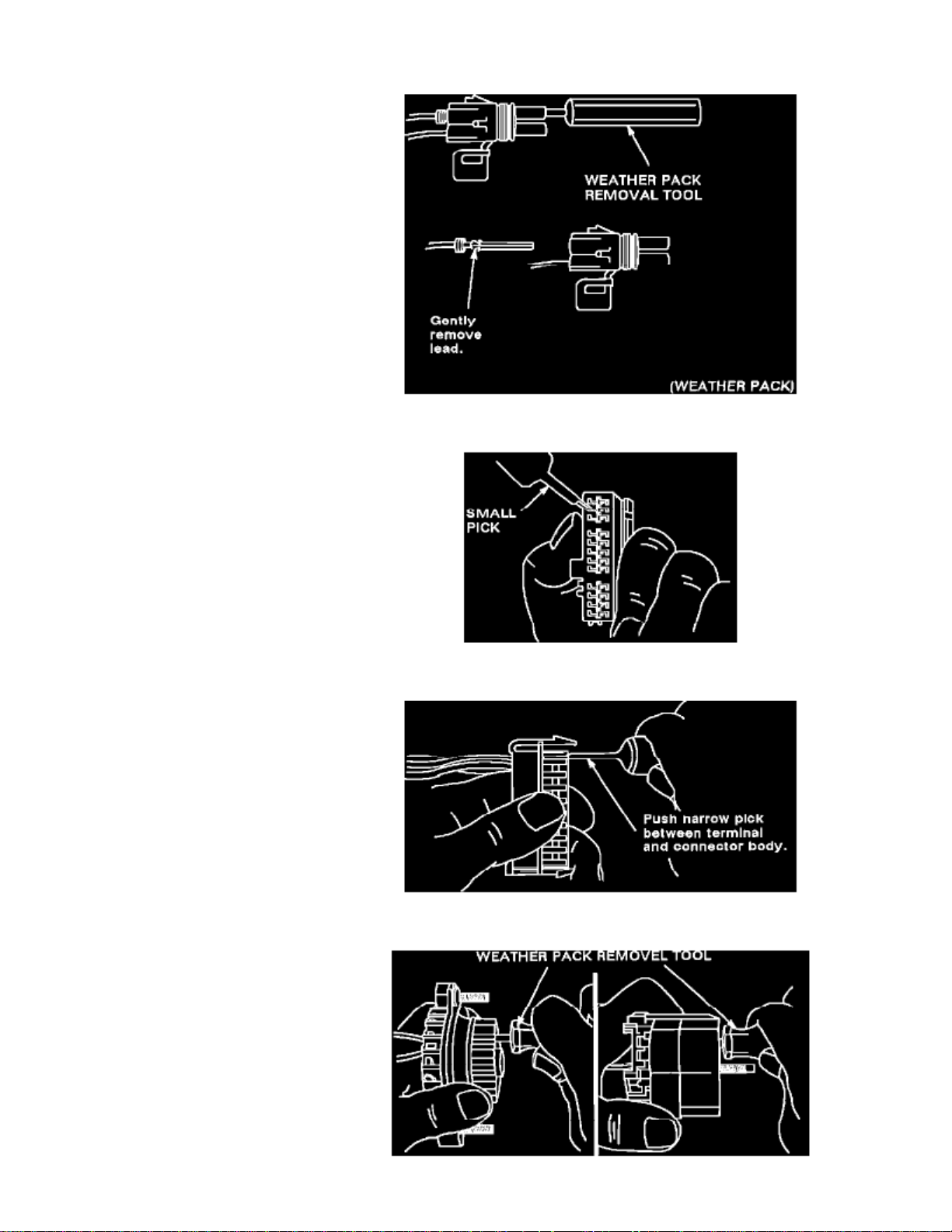
Figure 8
Figure 9
Figure 10
Page 93

> Relays and Modules > Relays and Modules - Accessories and Optional Equipment > Antitheft Relay > Component Information > Diagrams > Diagram Information and
Instructions > Page 59
Cutlass Supreme V6-3100 3.1L MFI VIN M (1994)
Figure 11
3. If terminal is to be re-used, re-form locking tang (see Figures 12 through 16).
Page 94

Figure 12
Figure 13
Figure 14
Figure 15
Page 95

> Relays and Modules > Relays and Modules - Accessories and Optional Equipment > Antitheft Relay > Component Information > Diagrams > Diagram Information and
Instructions > Page 60
Cutlass Supreme V6-3100 3.1L MFI VIN M (1994)
Figure 16
4. Make repair.
Page 96

When using a new terminal:a.
Slip cable seal away from terminal (if seal exist).
b. Cut wire as close to terminal as possible.
c. Slip a new cable seal onto wire (if necessary).
d. Strip 5mm (3/16") of insulation from wire.
e. Crimp a new terminal to the wire.
f. Solder with rosin core solder.
g. Slide cable seal toward terminal (if equipped with a seal).
h. Crimp cable seal and insulation (if equipped with a seal).
i. Apply grease to connectors outside the passenger compartment where the connector originally was equipped with grease.
Figure 17
To re-use a terminal or lead assembly, see previous steps c through i for repairs. Be sure to keep cable seal (if equipped) on terminal side of splice.
5. Insert lead from the back until it catches.
6. Install TPA's, CPA's and/or secondary locks, if equipped (see Figures 18 & 19).
Figure 18
Page 97

Figure 19
Page 98

> Relays and Modules > Relays and Modules - Accessories and Optional Equipment > Antitheft Relay > Component Information > Diagrams > Diagram Information and Instructions > Page 61
Harness Connector Face
Page 99

Page 100

> Relays and Modules > Relays and Modules - Accessories and Optional Equipment > Antitheft Relay > Component Information > Diagrams > Diagram Information and Instructions > Page 62
Antitheft Relay: Electrical Diagrams
 Loading...