

Page 1

oldsmobile :: Oldsmobile Cutlass Ciera V6-3100
3.1L MFI VIN M (1994)
Page 2

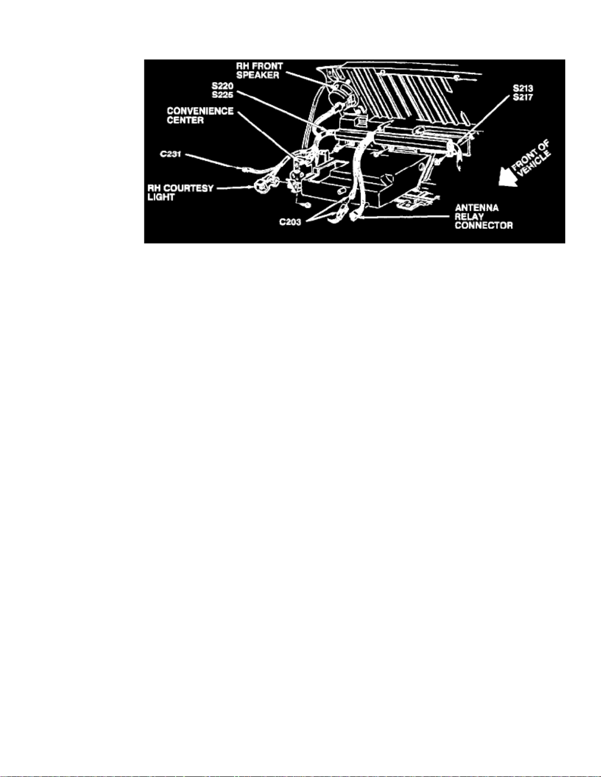
> Relays and Modules > Relays and Modules - Accessories and Optional Equipment > Antenna Relay > Component Information > Locations > Component Locations
Behind Center Of I/P
Page 3

Page 4
> Relays and Modules > Relays and Modules - Accessories and Optional Equipment > Antenna Relay > Component Information > Locations > Component Locations > Page 8
Behind RH Side Of I/P
Page 5

Page 6

> Relays and Modules > Relays and Modules - Accessories and Optional Equipment > Keyless Entry Module > Component Information > Locations
LH Side Of Luggage Compartment
Page 7

Page 8

> Relays and Modules > Relays and Modules - Accessories and Optional Equipment > Keyless Entry Module > Component Information > Locations > Page 12
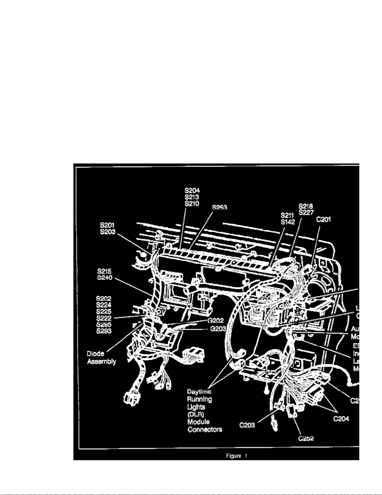
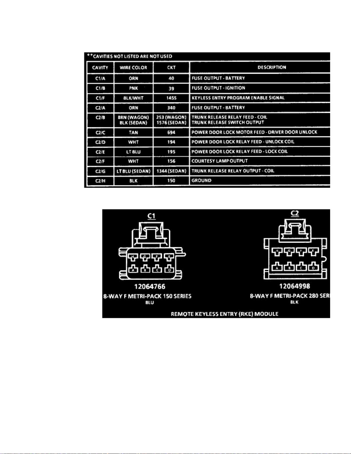
Keyless Entry Module: Diagrams
Remote Keyless Entry (RKE) Module
Remote Keyless Entry (RKE) Module
Page 9

Page 10

> Relays and Modules > Relays and Modules - Accessories and Optional Equipment > Relay Module > Component Information > Technical Service Bulletins > All Technical Service Bulletins for Relay Module: > 09-06-03-
004D > Dec > 10 > Electrical - MIL ON/DTC's Set By Various Control Modules
Relay Module: All Technical Service BulletinsElectrical - MIL ON/DTC's Set By Various Control Modules
TECHNICAL
09-06-03-004DBulletin No.:
December 08, 2010Date:
Subject:
Intermittent No Crank/No Start, No Module Communication, MIL, Warning Lights, Vehicle Messages or DTCs Set by Various ControlModules - Diagnosing and Repairing Fretting Corrosion (Disconnect Affected Connector and Apply Dielectric Lubricant)
Models:
2011 and Prior GM Passenger Cars and Trucks
Attention:
This repair can be applied to ANY electrical connection including, but not limited to: lighting, body electrical, in-line connections, powertrain controlsensors, etc. DO NOT over apply lubricant to the point where it prevents the full engagement of sealed connectors. A light coating on the terminalsurfaces is sufficient to correct the condition.
Supercede:This bulletin is being revised to update the Attention statement and add the 2011 model year. Please discard Corporate Bulletin Number 09-06-03-004C(Section 06 - Engine/Propulsion System).
Condition
Some customers may comment on any of the following conditions:
- An intermittent no crank/no start
- Intermittent malfunction indicator lamp (MIL) illumination
- Intermittent service lamp illumination
- Intermittent service message(s) being displayed
The technician may determine that he is unable to duplicate the intermittent condition.
Cause
- Vibration
- Thermal cycling
- Poor connection/terminal retention
- Micro motion
- A connector, component or wiring harness not properly secured resulting in movement
On low current signal circuits this condition may cause high resistance, resulting in intermittent connections.
On high current power circuits this condition may cause permanent increases in the resistance and may cause a device to become inoperative.
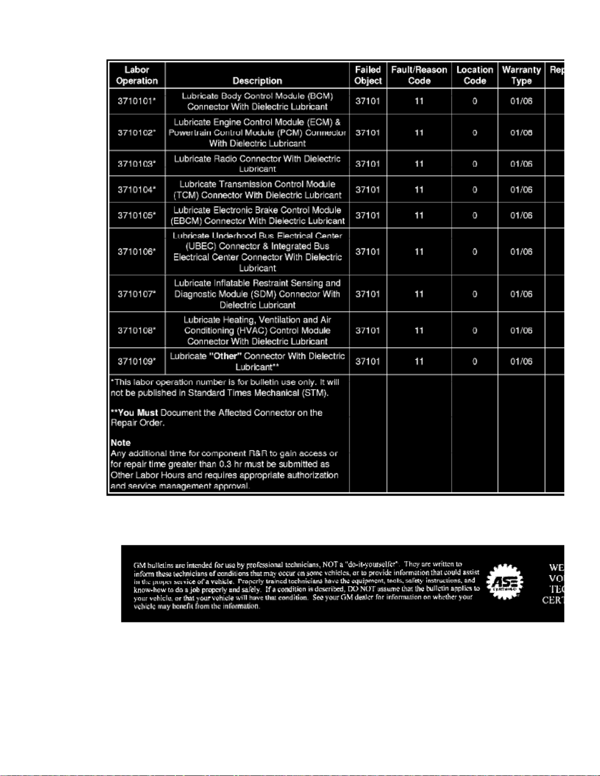
Representative List of Control Modules and Components
Page 11

> Relays and Modules > Relays and Modules - Accessories and Optional Equipment > Relay Module > Component Information > Technical Service Bulletins > All Technical
Service Bulletins for Relay Module: > 09-06-03-004D > Dec > 10 > Electrical - MIL ON/DTC's Set By Various Control Modules > Page 21
Cutlass Ciera V6-3100 3.1L MFI VIN M (1994)
This condition may be caused by a buildup of nonconductive insulating oxidized debris known as fretting corrosion, occurring between two electricalcontact surfaces of the connection or connector. This may be caused by any of the following conditions:
The following is only a representative list of control modules and components that may be affected by this connection or connector condition and include every possible module or component for every vehicle. DOESNOT
- Blower Control Module
- Body Control Module (BCM)
- Communication Interface Module (CIM)
- Cooling Fan Control Module
- Electronic Brake Control Module (EBCM)
- Electronic Brake and Traction Control Module (EBTCM)
- Electronic Suspension Control (ESC) Module
- Engine Control Module (ECM)
- Heating, Ventilation and Air Conditioning (HVAC) Control Module
Page 12

- HVAC Actuator
- Inflatable Restraint Sensing and Diagnostic Module (SDM)
- Any AIR BAG module
- Seatbelt Lap Anchor Pretensioner
- Seatbelt Retractor Pretensioner
- An SIR system connection or connector condition resulting in the following DTCs being set: B0015, B0016, B0019, B0020, B0022, or B0023
- Powertrain Control Module (PCM)
- Remote Control Door Lock Receiver (RCDLR)
- Transmission Control Module (TCM)
Correction
replace the control module, wiring or component for the following conditions: ImportantDO NOT
-
be duplicated. The condition is intermittent and cannot
-
be duplicated. The condition is present and by disconnecting and reconnecting the connector the condition can no longer
Use the following procedure to correct the conditions listed above.
1. Install a scan tool and perform the Diagnostic System Check - Vehicle. Retrieve and record any existing history or current DTCs from all of the
control modules (refer to SI).
If any DTC(s) are set, refer to Diagnostic Trouble Code (DTC) List - Vehicle to identify the connector(s) of the control module/component
which may be causing the condition (refer to SI).
If DTCs are not set, refer to Symptoms - Vehicle to identify the connector(s) of the control module/component which may be causing the
condition (refer to SI).
2. When identified, use the appropriate DTC Diagnostics, Symptoms, Schematics, Component Connector End Views and Component Locator
documents to locate and disconnect the affected harness connector(s) which are causing the condition.
ImportantDO NOT
apply an excessive amount of dielectric lubricant to the connectors as shown, as hydrolock may result when attempting to mate theconnectors. Use ONLY a clean nylon brush that is dedicated to the repair of the conditions in this bulletin.
3. With a one-inch nylon bristle brush, apply dielectric lubricant to both the module/component side and the harness side of the affected connector(s).
4. Reconnect the affected connector(s) and wipe away any excess lubricant that may be present. 5. Attempt to duplicate the condition by using the following information:
Page 13

> Relays and Modules > Relays and Modules - Accessories and Optional Equipment > Relay Module > Component Information > Technical Service Bulletins > All Technical
Service Bulletins for Relay Module: > 09-06-03-004D > Dec > 10 > Electrical - MIL ON/DTC's Set By Various Control Modules > Page 22
Cutlass Ciera V6-3100 3.1L MFI VIN M (1994)
Note
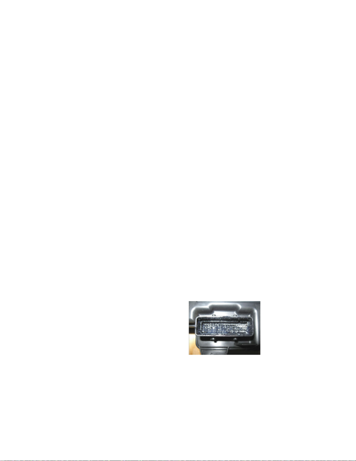
Fretting corrosion looks like little dark smudges on electrical terminals and appear where the actual electrical contact is being made. In less severecases it may be unable to be seen or identified without the use of a magnifying glass.
- DTC Diagnostic Procedure
- Circuit/System Description
- Conditions for Running the DTC
- Conditions for Setting the DTC
- Diagnostic Aids
- Circuit/System Verification
If the condition cannot be duplicated, the repair is complete. If the condition can be duplicated, then follow the appropriate DTC, Symptom or Circuit/System Testing procedure (refer to SI).
Repair Order Documentation
Page 14

be documented on the repair order. Failure to do so may result in a chargeback.ImportantThe following information MUST
- Customer vehicle condition.
- Was a Service Lamp or Service Message illuminated? If yes, specify which Service Lamp or Service Message.
- Was a DTC(s) set? If yes, specify which DTC(s) were set.
- After following the procedure contained within this bulletin, could the condition be duplicated?
If the condition duplicated, then document the affected module/component connector name and number on the repair order. was not
-
was
If the condition duplicated after the procedure contained within this bulletin was followed, and additional diagnosis led to the replacement ofa module or component, the SI Document ID Number be written on the repair order. MUST
Parts Information
Alternate Distributor For All of North America
Note
NyoGel(R) 760G Lubricant* is equivalent to GMSPO P/N 12377900, and P/N 10953529 (Canada), specified for use to correct the condition in thisbulletin.
*We believe this source and their products to be reliable. There may be additional manufacturers of such products/materials. General Motors does notendorse, indicate any preference for, or assume any responsibility for the products or material from this firm or for any such items that may be availablefrom other sources.
Warranty Information (excluding Saab Models)
For vehicles repaired under warranty, use the appropriate/closest labor operation depending upon the module/component connection that the dielectriclubricant was applied to:
Page 15

> Relays and Modules > Relays and Modules - Accessories and Optional Equipment > Relay Module > Component Information > Technical Service Bulletins > All Technical
Service Bulletins for Relay Module: > 09-06-03-004D > Dec > 10 > Electrical - MIL ON/DTC's Set By Various Control Modules > Page 23
Cutlass Ciera V6-3100 3.1L MFI VIN M (1994)
Warranty Information (Saab Models)
Page 16
For vehicles repaired under warranty, use the appropriate/closest labor operation depending upon the module/component connection that the dielectriclubricant was applied to refer to the table above.
Disclaimer
Page 17

Page 18

> Relays and Modules > Relays and Modules - Accessories and Optional Equipment > Relay Module > Component Information > Technical Service Bulletins > Customer Interest for Relay Module: > 09-06-03-004D > Dec > 10
> Electrical - MIL ON/DTC's Set By Various Control Modules
Relay Module: Customer InterestElectrical - MIL ON/DTC's Set By Various Control Modules
TECHNICAL
09-06-03-004DBulletin No.:
December 08, 2010Date:
Subject:
Intermittent No Crank/No Start, No Module Communication, MIL, Warning Lights, Vehicle Messages or DTCs Set by Various ControlModules - Diagnosing and Repairing Fretting Corrosion (Disconnect Affected Connector and Apply Dielectric Lubricant)
Models:
2011 and Prior GM Passenger Cars and Trucks
Attention:
This repair can be applied to ANY electrical connection including, but not limited to: lighting, body electrical, in-line connections, powertrain controlsensors, etc. DO NOT over apply lubricant to the point where it prevents the full engagement of sealed connectors. A light coating on the terminalsurfaces is sufficient to correct the condition.
Supercede:This bulletin is being revised to update the Attention statement and add the 2011 model year. Please discard Corporate Bulletin Number 09-06-03-004C(Section 06 - Engine/Propulsion System).
Condition
Some customers may comment on any of the following conditions:
- An intermittent no crank/no start
- Intermittent malfunction indicator lamp (MIL) illumination
- Intermittent service lamp illumination
- Intermittent service message(s) being displayed
The technician may determine that he is unable to duplicate the intermittent condition.
Cause
- Vibration
- Thermal cycling
- Poor connection/terminal retention
- Micro motion
- A connector, component or wiring harness not properly secured resulting in movement
On low current signal circuits this condition may cause high resistance, resulting in intermittent connections.
On high current power circuits this condition may cause permanent increases in the resistance and may cause a device to become inoperative.
Representative List of Control Modules and Components
Page 19

> Relays and Modules > Relays and Modules - Accessories and Optional Equipment > Relay Module > Component Information > Technical Service Bulletins > Customer
Interest for Relay Module: > 09-06-03-004D > Dec > 10 > Electrical - MIL ON/DTC's Set By Various Control Modules > Page 29
Cutlass Ciera V6-3100 3.1L MFI VIN M (1994)
This condition may be caused by a buildup of nonconductive insulating oxidized debris known as fretting corrosion, occurring between two electricalcontact surfaces of the connection or connector. This may be caused by any of the following conditions:
The following is only a representative list of control modules and components that may be affected by this connection or connector condition and include every possible module or component for every vehicle. DOESNOT
- Blower Control Module
- Body Control Module (BCM)
- Communication Interface Module (CIM)
- Cooling Fan Control Module
- Electronic Brake Control Module (EBCM)
- Electronic Brake and Traction Control Module (EBTCM)
- Electronic Suspension Control (ESC) Module
- Engine Control Module (ECM)
- Heating, Ventilation and Air Conditioning (HVAC) Control Module
Page 20
- HVAC Actuator
- Inflatable Restraint Sensing and Diagnostic Module (SDM)
- Any AIR BAG module
- Seatbelt Lap Anchor Pretensioner
- Seatbelt Retractor Pretensioner
- An SIR system connection or connector condition resulting in the following DTCs being set: B0015, B0016, B0019, B0020, B0022, or B0023
- Powertrain Control Module (PCM)
- Remote Control Door Lock Receiver (RCDLR)
- Transmission Control Module (TCM)
Correction
replace the control module, wiring or component for the following conditions: ImportantDO NOT
-
be duplicated. The condition is intermittent and cannot
-
be duplicated. The condition is present and by disconnecting and reconnecting the connector the condition can no longer
Use the following procedure to correct the conditions listed above.
1. Install a scan tool and perform the Diagnostic System Check - Vehicle. Retrieve and record any existing history or current DTCs from all of the
control modules (refer to SI).
If any DTC(s) are set, refer to Diagnostic Trouble Code (DTC) List - Vehicle to identify the connector(s) of the control module/component
which may be causing the condition (refer to SI).
If DTCs are not set, refer to Symptoms - Vehicle to identify the connector(s) of the control module/component which may be causing the
condition (refer to SI).
2. When identified, use the appropriate DTC Diagnostics, Symptoms, Schematics, Component Connector End Views and Component Locator
documents to locate and disconnect the affected harness connector(s) which are causing the condition.
ImportantDO NOT
apply an excessive amount of dielectric lubricant to the connectors as shown, as hydrolock may result when attempting to mate theconnectors. Use ONLY a clean nylon brush that is dedicated to the repair of the conditions in this bulletin.
3. With a one-inch nylon bristle brush, apply dielectric lubricant to both the module/component side and the harness side of the affected connector(s).
4. Reconnect the affected connector(s) and wipe away any excess lubricant that may be present. 5. Attempt to duplicate the condition by using the following information:
Page 21

> Relays and Modules > Relays and Modules - Accessories and Optional Equipment > Relay Module > Component Information > Technical Service Bulletins > Customer
Interest for Relay Module: > 09-06-03-004D > Dec > 10 > Electrical - MIL ON/DTC's Set By Various Control Modules > Page 30
Cutlass Ciera V6-3100 3.1L MFI VIN M (1994)
Note
Fretting corrosion looks like little dark smudges on electrical terminals and appear where the actual electrical contact is being made. In less severecases it may be unable to be seen or identified without the use of a magnifying glass.
- DTC Diagnostic Procedure
- Circuit/System Description
- Conditions for Running the DTC
- Conditions for Setting the DTC
- Diagnostic Aids
- Circuit/System Verification
If the condition cannot be duplicated, the repair is complete. If the condition can be duplicated, then follow the appropriate DTC, Symptom or Circuit/System Testing procedure (refer to SI).
Repair Order Documentation
Page 22

be documented on the repair order. Failure to do so may result in a chargeback.ImportantThe following information MUST
- Customer vehicle condition.
- Was a Service Lamp or Service Message illuminated? If yes, specify which Service Lamp or Service Message.
- Was a DTC(s) set? If yes, specify which DTC(s) were set.
- After following the procedure contained within this bulletin, could the condition be duplicated?
If the condition duplicated, then document the affected module/component connector name and number on the repair order. was not
-
was
If the condition duplicated after the procedure contained within this bulletin was followed, and additional diagnosis led to the replacement ofa module or component, the SI Document ID Number be written on the repair order. MUST
Parts Information
Alternate Distributor For All of North America
Note
NyoGel(R) 760G Lubricant* is equivalent to GMSPO P/N 12377900, and P/N 10953529 (Canada), specified for use to correct the condition in thisbulletin.
*We believe this source and their products to be reliable. There may be additional manufacturers of such products/materials. General Motors does notendorse, indicate any preference for, or assume any responsibility for the products or material from this firm or for any such items that may be availablefrom other sources.
Warranty Information (excluding Saab Models)
For vehicles repaired under warranty, use the appropriate/closest labor operation depending upon the module/component connection that the dielectriclubricant was applied to:
Page 23

> Relays and Modules > Relays and Modules - Accessories and Optional Equipment > Relay Module > Component Information > Technical Service Bulletins > Customer
Interest for Relay Module: > 09-06-03-004D > Dec > 10 > Electrical - MIL ON/DTC's Set By Various Control Modules > Page 31
Cutlass Ciera V6-3100 3.1L MFI VIN M (1994)
Warranty Information (Saab Models)
Page 24

For vehicles repaired under warranty, use the appropriate/closest labor operation depending upon the module/component connection that the dielectriclubricant was applied to refer to the table above.
Disclaimer
Page 25

Page 26
> Relays and Modules > Relays and Modules - Body and Frame > Door Module > Component Information > Technical Service Bulletins > Auto Unlock Module - Location
Door Module: Technical Service BulletinsAuto Unlock Module - Location
File In Section: 8 - Chassis/Body Electrical
Bulletin No.: 43-81-30
Date: November, 1994
Subject:Section 8A - Auto Unlock Module Location
Models:1994 Buick Century1994 Oldsmobile Cutlass Ciera
Page 27

This bulletin contains revisions to Section 8A-11, 8A-14, 8A-131 and 8A-201.
Auto unlock module is located on the LH side of I/P (Instrument Panel) left of the steering column.
Page 28

> Relays and Modules > Relays and Modules - Body and Frame > Keyless Entry Module > Component Information > Locations
LH Side Of Luggage Compartment
Page 29

Page 30
> Relays and Modules > Relays and Modules - Body and Frame > Keyless Entry Module > Component Information > Locations > Page 40
Keyless Entry Module: Diagrams
Remote Keyless Entry (RKE) Module
Remote Keyless Entry (RKE) Module
Page 31

Page 32

> Relays and Modules > Relays and Modules - Body and Frame > Auto Door Unlock Module <--> [Power Door Lock Control Module] > Component Information > Locations
Auto Door Unlock Module: Locations
NOTE: The OEM service manual does not provide a location image for this module.
Auto Door Unlock Module is located at the RH side of I/P heater duct.
Page 33

Page 34
> Relays and Modules > Relays and Modules - Body and Frame > Auto Door Unlock Module <--> [Power Door Lock Control Module] > Component Information > Locations > Page 44
Autodoor Unlock Module
Page 35

Page 36

> Relays and Modules > Relays and Modules - Body and Frame > Power Door Lock Relay > Component Information > Technical Service Bulletins > Recalls for Power Door Lock Relay: > 94C50 > Sep > 94 > Recall -
Automatic Power Door Lock Relay Short
Technical Service Bulletin # 94C50
Recall - Automatic Power Door Lock Relay Short
NUMBER: 94-C-50CORP.REF.NO.:DATE: SEPTEMBER 1994SECTION: 8C
SUBJECT:AUTOMATIC POWER DOOR LOCK RELAY
YEAR:1994
MODEL:CUTLASS CIERA
General Information
TO: All Oldsmobile Retailers
The National Traffic and Motor Vehicle Safety Act, as amended, provides that each vehicle subject to a recall campaign of this type must be adequatelyrepaired within a reasonable time after the owner has tendered it for repair. A failure to repair within sixty (60) days after tender of a vehicle is primafacie evidence of failure to repair within a reasonable time.
If the condition is not adequately repaired within a reasonable time, the owner may be entitled to an identical or reasonably equivalent vehicle at nocharge or to a refund of the purchase price less a reasonable allowance for depreciation.
To avoid having to provide these burdensome solutions, every effort must be made to promptly schedule an appointment with each owner and to repairtheir vehicle as soon as possible. As you will see in reading the included copy of the letter that is being sent to owners, the owners are being instructed tocontact the Oldsmobile Customer Assistance Network (OCAN) if their retailer does not remedy the condition within five (5) days of the mutually agreedupon service date. If the condition is not remedied within a reasonable time, they are instructed on how to contact the National Highway Traffic SafetyAdministration.
DEFECT INVOLVED
To prevent the possibility of this condition from occurring, retailers are to replace the power door lock relay and any corroded terminals. In addition, thenew relay will be relocated to an area where water intrusion is less likely.
VEHICLES INVOLVED
Certain 1994 Oldsmobile Cutlass Ciera vehicles within the breakpoints are listed. See illustration.
Page 37

> Relays and Modules > Relays and Modules - Body and Frame > Power Door Lock Relay > Component Information > Technical Service Bulletins > Recalls for Power Door
Lock Relay: > 94C50 > Sep > 94 > Recall - Automatic Power Door Lock Relay Short > Page 53
Cutlass Ciera V6-3100 3.1L MFI VIN M (1994)
General Motors has determined that a defect which relates to motor vehicle safety exists in certain 1994 Oldsmobile Cutlass Ciera model vehicles. Someof these vehicles were built with a power door lock relay that can short internally due to water intrusion. If this occurs, a vehicle fire could occur withoutprior warning.
Involved vehicles have been identified by Vehicle Identification Number listings. Computer listings contain the complete vehicle identification number,owner name and address data, and are furnished to involved retailers with the campaign bulletin. Owner name and address data furnished will enableretailers to follow-up with owners involved in this campaign.
These listings may contain owner names and addresses obtained from State Motor Vehicle Registration Records. The use of such motor vehicleregistration data for any other purpose is a violation of law in several states. Accordingly, you are urged to limit the use of this listing to the follow-upnecessary to complete this campaign. Any retailer not receiving a computer listing with the campaign bulletin has no involved vehicles currentlyassigned.
All vehicles listed on the retailer's printout will require correction. Other suspect vehicles should be checked for campaign involvement by utilizing theVehicle Information Service System (V.I.S.S.).
PARTS INFORMATION
Page 38

Approximately 20% of the anticipated required parts will be pre-shipped to retailer facilities on or about the week of September 15, 1994. The parts willbe charged to the retailer's open account.
If additional parts are required to complete this campaign, they are to be obtained from GMSPO (General Motors Service Paris Operations). To ensurethese parts will be obtained as soon as possible, they should be ordered from GMSPO on a C.I.O. order, with NO special instruction code, but order onan advise code (2).
OWNER NOTIFICATION Owners will be notified of this recall on their vehicles by Oldsmobile Division (see copy of the owner letter included with this bulletin).
RETAIL CAMPAIGN RESPONSIBILITY
All unsold new vehicles in retailers' possession and subject to this campaign must be held and inspected/repaired per the service procedure of thiscampaign bulletin before owners take possession of these vehicles. After campaign is completed, the vehicle may be released for sale/delivery.
Retailers are to service all vehicles subject to this campaign at no charge to owners, regardless of mileage, age of vehicle, or ownership, from this timeforward.
In summary, whenever a vehicle subject to this campaign is taken into your new or used vehicle inventory, or it is in your retail facility for service in thefuture, please take the steps necessary to be sure the campaign correction has been made before selling or releasing the vehicle. Your cooperation incompleting this campaign as soon as possible will be greatly appreciated.
Service Procedure
1. Raise and support the hood.
2.
Disconnect negative battery cable. NOTICE: Prior to disconnecting the battery cable, preset radio stations should be reviewed and recorded so thatthey may be reset prior to delivery to customer.
3. Remove the right side sound insulator from below instrument panel and right side shroud finishing panel molding (forward of the carpet retainer).
4. Reposition carpet at the right side cowl panel to expose electrical wiring harness.
5. Remove relay from cavity in front body hinge pillar.
Page 39

> Relays and Modules > Relays and Modules - Body and Frame > Power Door Lock Relay > Component Information > Technical Service Bulletins > Recalls for Power Door
Lock Relay: > 94C50 > Sep > 94 > Recall - Automatic Power Door Lock Relay Short > Page 54
Cutlass Ciera V6-3100 3.1L MFI VIN M (1994)
Owners of vehicles recently sold from your new vehicle inventory with no owner information indicated on the retailer listing are to be contacted by theretailer, and arrangements made to make the required correction according to the instructions contained in this bulletin. This could be done by mailing tosuch owners a copy of the owner's letter included in this bulletin. Campaign follow-up cards should not be used for this purpose, since the owner may notas yet have received the notification letter.
Page 40

NOTICE:
Relay is covered in foam to prevent rattles and has a six (6) terminal connector (see Figure 1).
6.
Remove and discard relay and inspect all terminals on connector for corrosion. If no corrosion is present, proceed to step 9, otherwise, continue tostep 7.
Page 41

> Relays and Modules > Relays and Modules - Body and Frame > Power Door Lock Relay > Component Information > Technical Service Bulletins > Recalls for Power Door
Lock Relay: > 94C50 > Sep > 94 > Recall - Automatic Power Door Lock Relay Short > Page 55
Cutlass Ciera V6-3100 3.1L MFI VIN M (1994)
7. Replace connector terminals (see Figure 1).
8.
Since corrosion was present, the right upper body side hinge strap may not be properly sealed to the hinge pillar at the front edge of the hinge strap(see Figure 2).
Reseal hinge strap to pillar at upper front corner and front side using a clear flow grade sealer such as 3M Ultra Pro # 08302, American Sure Seal# CSC, Kent # 10200, or equivalent (see Figure 2).
Page 42

NOTICE:
Access for the sealer application to front edge can be done through the front opening of the door to fender with door in full open position.Apply material on an acid brush, and paddle sealing material into position.
9. Install new relay to connector.
10. Reposition and tape relay to harness with connector pointing down as shown in Figure 3.
NOTICE:
DO NOT install new relay in original position.
11. Reinstall carpet, right side shroud finishing panel molding and sound insulator panel molding and sound insulator panel.
12. Reconnect battery cable and reset radio presets.
13. Install a Campaign Identification Label.
Campaign Identification Label
Page 43

> Relays and Modules > Relays and Modules - Body and Frame > Power Door Lock Relay > Component Information > Technical Service Bulletins > Recalls for Power Door
Lock Relay: > 94C50 > Sep > 94 > Recall - Automatic Power Door Lock Relay Short > Page 56
Cutlass Ciera V6-3100 3.1L MFI VIN M (1994)
Each label provides space to print the campaign number and the five (5) digit retailer code of the retailer performing the campaign. Insert thisinformation with a typewriter or ball-point pen. When installing label, clean and dry the surface of the radiator support tie bar and apply the campaignlabel where it is readily visible.
Each Campaign Identification Label is to be located on the radiator core support in an area which will be visible when the vehicle is brought in forperiodic servicing by the owner.
Warranty Claim Information
Page 44

Submit claims using only one, of the "V" labor-ops for each vehicle:
Parts Allowance:Current retailer price, plus 40% allowance for handling.
Owner Letter
September 1994
Dear Oldsmobile Cutlass Ciera Owner:
This notice is sent to you in accordance with the requirements of the National Traffic and Motor Vehicle Safety Act.
REASON FOR THIS SAFETY RECALL:General Motors has determined that a defect which relates to motor vehicle safety exists in certain 1994 Oldsmobile Cutlass Ciera model vehicles. Someof these vehicles were built with a power door lock relay that can short internally due to water intrusion. If this occurs, a vehicle fire could occur withoutprior warning.
WHAT WE WILL DO:To prevent the possibility of this condition from occurring, retailers are to replace the power door lock relay and any corroded terminals. In addition, thenew relay will be relocated to an area where water intrusion is less likely. This service will be performed for you at no charge.
WHAT YOU SHOULD DO:Please contact your Oldsmobile retailer immediately to arrange a service date. Instructions have been sent to your retailer. It is estimated that parts willbe available to your retailer September 15, 1994. Please ask your retailer if you wish an estimate of the total time needed to schedule, process and returnyour vehicle. Included in this time would be about forty-five (45) minutes for a technician to perform the work required.
Your Oldsmobile retailer is best equipped to obtain parts and provide service to promptly correct your vehicle. However, if you take your vehicle to yourretailer on the agreed service date, and they do not remedy this condition then or within five days, we suggest you call Oldsmobile Customer Assistance(1-800-442-6537). Deaf, hearing impaired, or speech impaired persons with telecommunications devices for the deaf (TDD/TTY) may contactOldsmobile Customer Assistance at 1-800-TDD-OLDS (1-800-833-6537). They will assist you and the retailer in getting your vehicle corrected.
After contacting your retailer and Oldsmobile Customer Assistance, if you are still not satisfied that we have done our best to remedy this conditionwithout charge and within a reasonable time, you may write the Administrator, National Highway Traffic Safety Administration, 400 Seventh St., S.W.,Washington, D.C. 20590 or call 800-424-9393 (Washington, D.C. residents call 366-0123).
OWNER REPLY CARD:The enclosed owner reply card identifies your vehicle. Presentation of this card to your retailer will assist in making the necessary correction in theshortest possible time. If you have sold or traded your vehicle, please let us know by completing the postage paid reply card and returning it to us.
We are sorry to cause you this inconvenience; however, we have taken this action for your safety and continued satisfaction with our products.
Page 45

Page 46

> Relays and Modules > Relays and Modules - Body and Frame > Power Door Lock Relay > Component Information > Technical Service Bulletins > All Technical Service Bulletins for Power Door Lock Relay: > 94C50 > Sep
> 94 > Recall - Automatic Power Door Lock Relay Short
Technical Service Bulletin # 94C50
Recall - Automatic Power Door Lock Relay Short
NUMBER: 94-C-50CORP.REF.NO.:DATE: SEPTEMBER 1994SECTION: 8C
SUBJECT:AUTOMATIC POWER DOOR LOCK RELAY
YEAR:1994
MODEL:CUTLASS CIERA
General Information
TO: All Oldsmobile Retailers
The National Traffic and Motor Vehicle Safety Act, as amended, provides that each vehicle subject to a recall campaign of this type must be adequatelyrepaired within a reasonable time after the owner has tendered it for repair. A failure to repair within sixty (60) days after tender of a vehicle is primafacie evidence of failure to repair within a reasonable time.
If the condition is not adequately repaired within a reasonable time, the owner may be entitled to an identical or reasonably equivalent vehicle at nocharge or to a refund of the purchase price less a reasonable allowance for depreciation.
To avoid having to provide these burdensome solutions, every effort must be made to promptly schedule an appointment with each owner and to repairtheir vehicle as soon as possible. As you will see in reading the included copy of the letter that is being sent to owners, the owners are being instructed tocontact the Oldsmobile Customer Assistance Network (OCAN) if their retailer does not remedy the condition within five (5) days of the mutually agreedupon service date. If the condition is not remedied within a reasonable time, they are instructed on how to contact the National Highway Traffic SafetyAdministration.
DEFECT INVOLVED
To prevent the possibility of this condition from occurring, retailers are to replace the power door lock relay and any corroded terminals. In addition, thenew relay will be relocated to an area where water intrusion is less likely.
VEHICLES INVOLVED
Certain 1994 Oldsmobile Cutlass Ciera vehicles within the breakpoints are listed. See illustration.
Page 47

> Relays and Modules > Relays and Modules - Body and Frame > Power Door Lock Relay > Component Information > Technical Service Bulletins > All Technical Service
Bulletins for Power Door Lock Relay: > 94C50 > Sep > 94 > Recall - Automatic Power Door Lock Relay Short > Page 62
Cutlass Ciera V6-3100 3.1L MFI VIN M (1994)
General Motors has determined that a defect which relates to motor vehicle safety exists in certain 1994 Oldsmobile Cutlass Ciera model vehicles. Someof these vehicles were built with a power door lock relay that can short internally due to water intrusion. If this occurs, a vehicle fire could occur withoutprior warning.
Involved vehicles have been identified by Vehicle Identification Number listings. Computer listings contain the complete vehicle identification number,owner name and address data, and are furnished to involved retailers with the campaign bulletin. Owner name and address data furnished will enableretailers to follow-up with owners involved in this campaign.
These listings may contain owner names and addresses obtained from State Motor Vehicle Registration Records. The use of such motor vehicleregistration data for any other purpose is a violation of law in several states. Accordingly, you are urged to limit the use of this listing to the follow-upnecessary to complete this campaign. Any retailer not receiving a computer listing with the campaign bulletin has no involved vehicles currentlyassigned.
All vehicles listed on the retailer's printout will require correction. Other suspect vehicles should be checked for campaign involvement by utilizing theVehicle Information Service System (V.I.S.S.).
PARTS INFORMATION
Page 48
Approximately 20% of the anticipated required parts will be pre-shipped to retailer facilities on or about the week of September 15, 1994. The parts willbe charged to the retailer's open account.
If additional parts are required to complete this campaign, they are to be obtained from GMSPO (General Motors Service Paris Operations). To ensurethese parts will be obtained as soon as possible, they should be ordered from GMSPO on a C.I.O. order, with NO special instruction code, but order onan advise code (2).
OWNER NOTIFICATION Owners will be notified of this recall on their vehicles by Oldsmobile Division (see copy of the owner letter included with this bulletin).
RETAIL CAMPAIGN RESPONSIBILITY
All unsold new vehicles in retailers' possession and subject to this campaign must be held and inspected/repaired per the service procedure of thiscampaign bulletin before owners take possession of these vehicles. After campaign is completed, the vehicle may be released for sale/delivery.
Retailers are to service all vehicles subject to this campaign at no charge to owners, regardless of mileage, age of vehicle, or ownership, from this timeforward.
In summary, whenever a vehicle subject to this campaign is taken into your new or used vehicle inventory, or it is in your retail facility for service in thefuture, please take the steps necessary to be sure the campaign correction has been made before selling or releasing the vehicle. Your cooperation incompleting this campaign as soon as possible will be greatly appreciated.
Service Procedure
1. Raise and support the hood.
2.
Disconnect negative battery cable. NOTICE: Prior to disconnecting the battery cable, preset radio stations should be reviewed and recorded so thatthey may be reset prior to delivery to customer.
3. Remove the right side sound insulator from below instrument panel and right side shroud finishing panel molding (forward of the carpet retainer).
4. Reposition carpet at the right side cowl panel to expose electrical wiring harness.
5. Remove relay from cavity in front body hinge pillar.
Page 49

> Relays and Modules > Relays and Modules - Body and Frame > Power Door Lock Relay > Component Information > Technical Service Bulletins > All Technical Service
Bulletins for Power Door Lock Relay: > 94C50 > Sep > 94 > Recall - Automatic Power Door Lock Relay Short > Page 63
Cutlass Ciera V6-3100 3.1L MFI VIN M (1994)
Owners of vehicles recently sold from your new vehicle inventory with no owner information indicated on the retailer listing are to be contacted by theretailer, and arrangements made to make the required correction according to the instructions contained in this bulletin. This could be done by mailing tosuch owners a copy of the owner's letter included in this bulletin. Campaign follow-up cards should not be used for this purpose, since the owner may notas yet have received the notification letter.
Page 50
NOTICE:
Relay is covered in foam to prevent rattles and has a six (6) terminal connector (see Figure 1).
6.
Remove and discard relay and inspect all terminals on connector for corrosion. If no corrosion is present, proceed to step 9, otherwise, continue tostep 7.
Page 51

> Relays and Modules > Relays and Modules - Body and Frame > Power Door Lock Relay > Component Information > Technical Service Bulletins > All Technical Service
Bulletins for Power Door Lock Relay: > 94C50 > Sep > 94 > Recall - Automatic Power Door Lock Relay Short > Page 64
Cutlass Ciera V6-3100 3.1L MFI VIN M (1994)
7. Replace connector terminals (see Figure 1).
8.
Since corrosion was present, the right upper body side hinge strap may not be properly sealed to the hinge pillar at the front edge of the hinge strap(see Figure 2).
Reseal hinge strap to pillar at upper front corner and front side using a clear flow grade sealer such as 3M Ultra Pro # 08302, American Sure Seal# CSC, Kent # 10200, or equivalent (see Figure 2).
Page 52

NOTICE:
Access for the sealer application to front edge can be done through the front opening of the door to fender with door in full open position.Apply material on an acid brush, and paddle sealing material into position.
9. Install new relay to connector.
10. Reposition and tape relay to harness with connector pointing down as shown in Figure 3.
NOTICE:
DO NOT install new relay in original position.
11. Reinstall carpet, right side shroud finishing panel molding and sound insulator panel molding and sound insulator panel.
12. Reconnect battery cable and reset radio presets.
13. Install a Campaign Identification Label.
Campaign Identification Label
Page 53

> Relays and Modules > Relays and Modules - Body and Frame > Power Door Lock Relay > Component Information > Technical Service Bulletins > All Technical Service
Bulletins for Power Door Lock Relay: > 94C50 > Sep > 94 > Recall - Automatic Power Door Lock Relay Short > Page 65
Cutlass Ciera V6-3100 3.1L MFI VIN M (1994)
Each label provides space to print the campaign number and the five (5) digit retailer code of the retailer performing the campaign. Insert thisinformation with a typewriter or ball-point pen. When installing label, clean and dry the surface of the radiator support tie bar and apply the campaignlabel where it is readily visible.
Each Campaign Identification Label is to be located on the radiator core support in an area which will be visible when the vehicle is brought in forperiodic servicing by the owner.
Warranty Claim Information
Page 54

Submit claims using only one, of the "V" labor-ops for each vehicle:
Parts Allowance:Current retailer price, plus 40% allowance for handling.
Owner Letter
September 1994
Dear Oldsmobile Cutlass Ciera Owner:
This notice is sent to you in accordance with the requirements of the National Traffic and Motor Vehicle Safety Act.
REASON FOR THIS SAFETY RECALL:General Motors has determined that a defect which relates to motor vehicle safety exists in certain 1994 Oldsmobile Cutlass Ciera model vehicles. Someof these vehicles were built with a power door lock relay that can short internally due to water intrusion. If this occurs, a vehicle fire could occur withoutprior warning.
WHAT WE WILL DO:To prevent the possibility of this condition from occurring, retailers are to replace the power door lock relay and any corroded terminals. In addition, thenew relay will be relocated to an area where water intrusion is less likely. This service will be performed for you at no charge.
WHAT YOU SHOULD DO:Please contact your Oldsmobile retailer immediately to arrange a service date. Instructions have been sent to your retailer. It is estimated that parts willbe available to your retailer September 15, 1994. Please ask your retailer if you wish an estimate of the total time needed to schedule, process and returnyour vehicle. Included in this time would be about forty-five (45) minutes for a technician to perform the work required.
Your Oldsmobile retailer is best equipped to obtain parts and provide service to promptly correct your vehicle. However, if you take your vehicle to yourretailer on the agreed service date, and they do not remedy this condition then or within five days, we suggest you call Oldsmobile Customer Assistance(1-800-442-6537). Deaf, hearing impaired, or speech impaired persons with telecommunications devices for the deaf (TDD/TTY) may contactOldsmobile Customer Assistance at 1-800-TDD-OLDS (1-800-833-6537). They will assist you and the retailer in getting your vehicle corrected.
After contacting your retailer and Oldsmobile Customer Assistance, if you are still not satisfied that we have done our best to remedy this conditionwithout charge and within a reasonable time, you may write the Administrator, National Highway Traffic Safety Administration, 400 Seventh St., S.W.,Washington, D.C. 20590 or call 800-424-9393 (Washington, D.C. residents call 366-0123).
OWNER REPLY CARD:The enclosed owner reply card identifies your vehicle. Presentation of this card to your retailer will assist in making the necessary correction in theshortest possible time. If you have sold or traded your vehicle, please let us know by completing the postage paid reply card and returning it to us.
We are sorry to cause you this inconvenience; however, we have taken this action for your safety and continued satisfaction with our products.
Page 55

Page 56

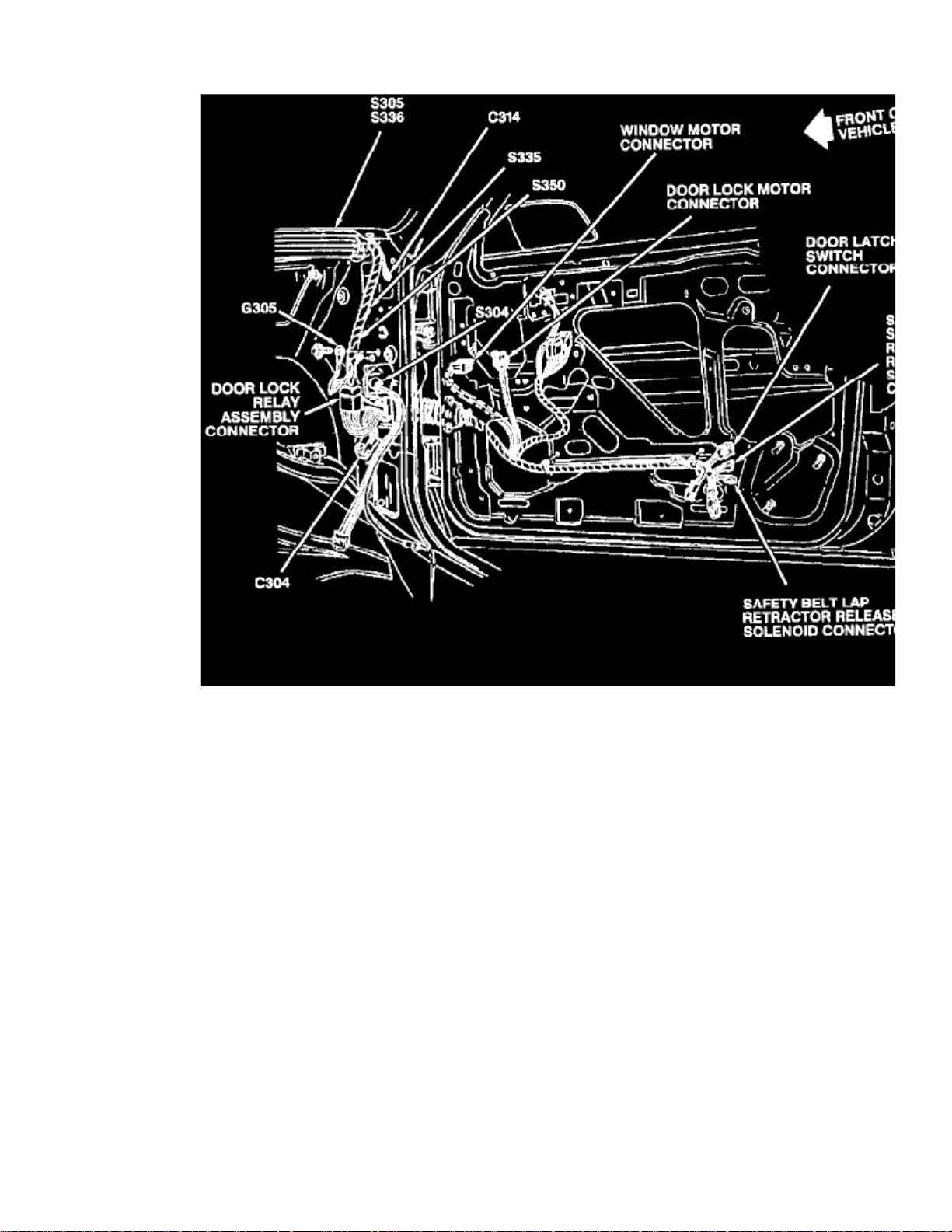
> Relays and Modules > Relays and Modules - Body and Frame > Power Door Lock Relay > Component Information > Locations > Component Locations
Power Door Lock Relay: Component Locations
RH Shroud And Door
The Door Lock Relay Assembly is located on the RH shroud.
Page 57

Page 58
> Relays and Modules > Relays and Modules - Body and Frame > Power Door Lock Relay > Component Information > Locations > Component Locations > Page 68
RH Shroud And Door
Page 59

Page 60

> Relays and Modules > Relays and Modules - Body and Frame > Power Door Lock Relay > Component Information > Locations > Page 69
Door Lock Relay Assembly
Page 61

Page 62
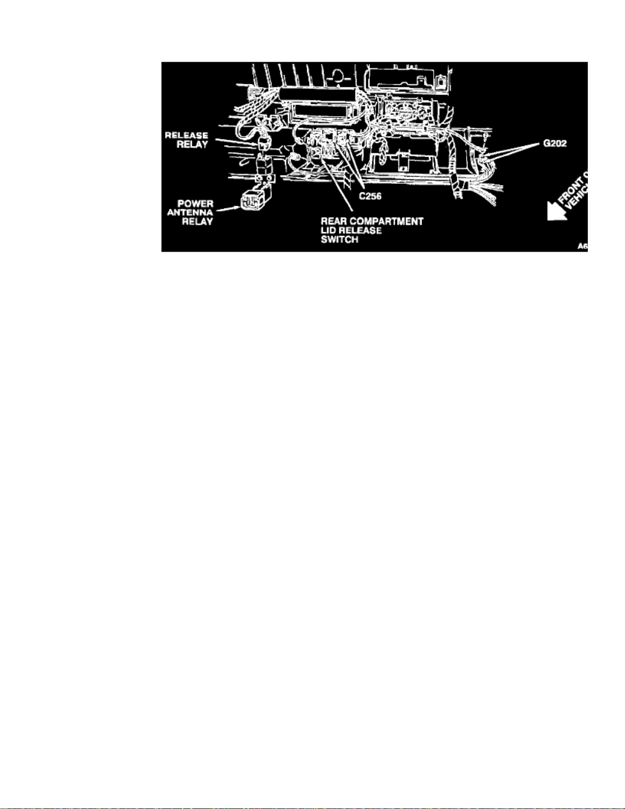
> Relays and Modules > Relays and Modules - Body and Frame > Trunk / Liftgate Relay > Component Information > Locations
Behind Center Of I/P
Page 63

Page 64
> Relays and Modules > Relays and Modules - Body and Frame > Trunk / Liftgate Relay > Component Information > Locations > Page 73
Release Relay
Page 65

Page 66
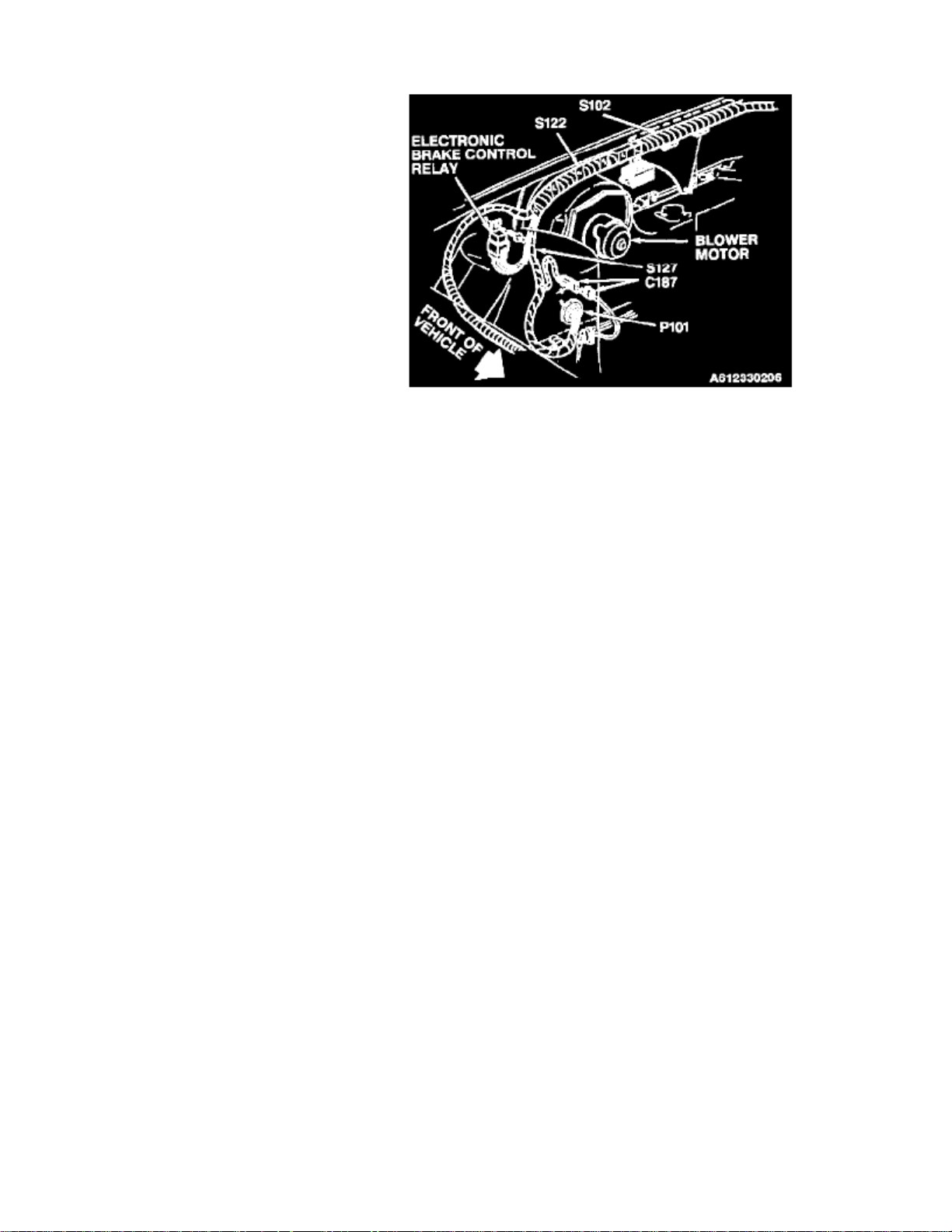
> Relays and Modules > Relays and Modules - Brakes and Traction Control > ABS Main Relay > Component Information > Locations
RH Rear Of Engine Compartment
Page 67

Page 68

> Relays and Modules > Relays and Modules - Brakes and Traction Control > ABS Main Relay > Component Information > Locations > Page 78
Electronic Brake Control Relay
Page 69

Page 70
> Relays and Modules > Relays and Modules - Brakes and Traction Control > Brake Fluid Solenoid Valve Relay > Component Information > Locations > LH Front
Brake Fluid Solenoid Valve Relay: LocationsLH Front
LH Rear Of Engine Compartment
Left Front ABS Solenoid is located at the LH side of shock tower, on ABS Master Cylinder
Page 71

Page 72

> Relays and Modules > Relays and Modules - Brakes and Traction Control > Brake Fluid Solenoid Valve Relay > Component Information > Locations > LH Front > Page 83
LH Rear Of Engine Compartment
Page 73

Page 74

> Relays and Modules > Relays and Modules - Brakes and Traction Control > Electronic Brake Control Module > Component Information > Technical Service Bulletins > Customer Interest for Electronic Brake Control Module:
> 73-50-26 > Aug > 97 > Brakes - ABS Light ON, DTC 46 & 86 (C1246 & C1286)
Electronic Brake Control Module: Customer InterestBrakes - ABS Light ON, DTC 46 & 86 (C1246 & C1286)
File In Section: 5 - Brakes
Bulletin No.: 73-50-26
Date: August, 1997
Subject: ABS Light On - DTC's 46 and 86 Set(Perform Diagnostic Procedure, Replace Center ABS Motor Pinion)
Models: 1991-97 Buick Skylark1992-97 Buick Regal1994-97 Buick Century1992-96 Chevrolet Beretta, Corsica, Lumina APV1992-97 Chevrolet Cavalier, Lumina,1993-97 Chevrolet Camaro1995-97 Chevrolet Monte Carlo1997
Chevrolet Malibu, Venture
1993-97 Geo Prizm1995-97 Geo Metro1996-97 Geo Tracker1991
Oldsmobile Calais
1992-96 Oldsmobile Cutlass Ciera1992-97 Oldsmobile Achieva, Cutlass Supreme, Silhouette1997
Oldsmobile Cutlass
1998 Oldsmobile Intrigue
1991-97 Pontiac Grand Am1992-94 Pontiac Sunbird1992-97 Pontiac Grand Prix, Trans Sport1993-97 Pontiac Firebird, Trans Am1995-97 Pontiac Sunfire
Condition
Some owners may comment that the ABS light is on with Diagnostic Trouble Codes (DTC's) 46 and 86 set (rear ABS channel will not move) as currentor history. (DTC's 46 and 86 will be displayed as C1246 and C1286 on 1997 and 1998 model year vehicles).
Cause
A condition exists where the ABS motor pack gear (pinion) will bind on the motor armature shaft causing the motor not to move when commanded bythe EBCM. This condition is aggravated by light corrosion between the pinion and shaft. Therefore, it may occur more frequently when the weather ishot and humid.
Important:
Other EBCM and ABS motor pack concerns can also cause this condition, but they are not as common as the above cause.
Correction
Page 75

> Relays and Modules > Relays and Modules - Brakes and Traction Control > Electronic Brake Control Module > Component Information > Technical Service Bulletins >
Customer Interest for Electronic Brake Control Module: > 73-50-26 > Aug > 97 > Brakes - ABS Light ON, DTC 46 & 86 (C1246 & C1286) > Page 92
Cutlass Ciera V6-3100 3.1L MFI VIN M (1994)
Page 76

Page 77

> Relays and Modules > Relays and Modules - Brakes and Traction Control > Electronic Brake Control Module > Component Information > Technical Service Bulletins >
Customer Interest for Electronic Brake Control Module: > 73-50-26 > Aug > 97 > Brakes - ABS Light ON, DTC 46 & 86 (C1246 & C1286) > Page 93
Cutlass Ciera V6-3100 3.1L MFI VIN M (1994)
Page 78
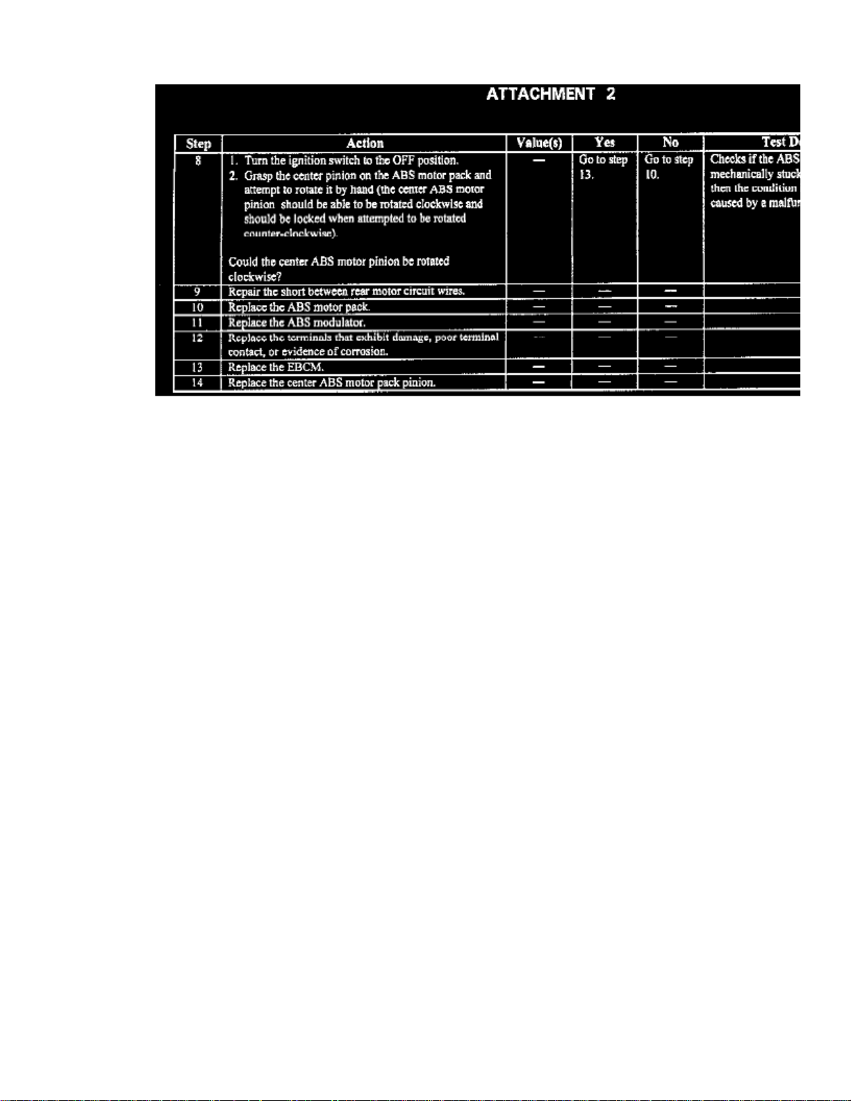
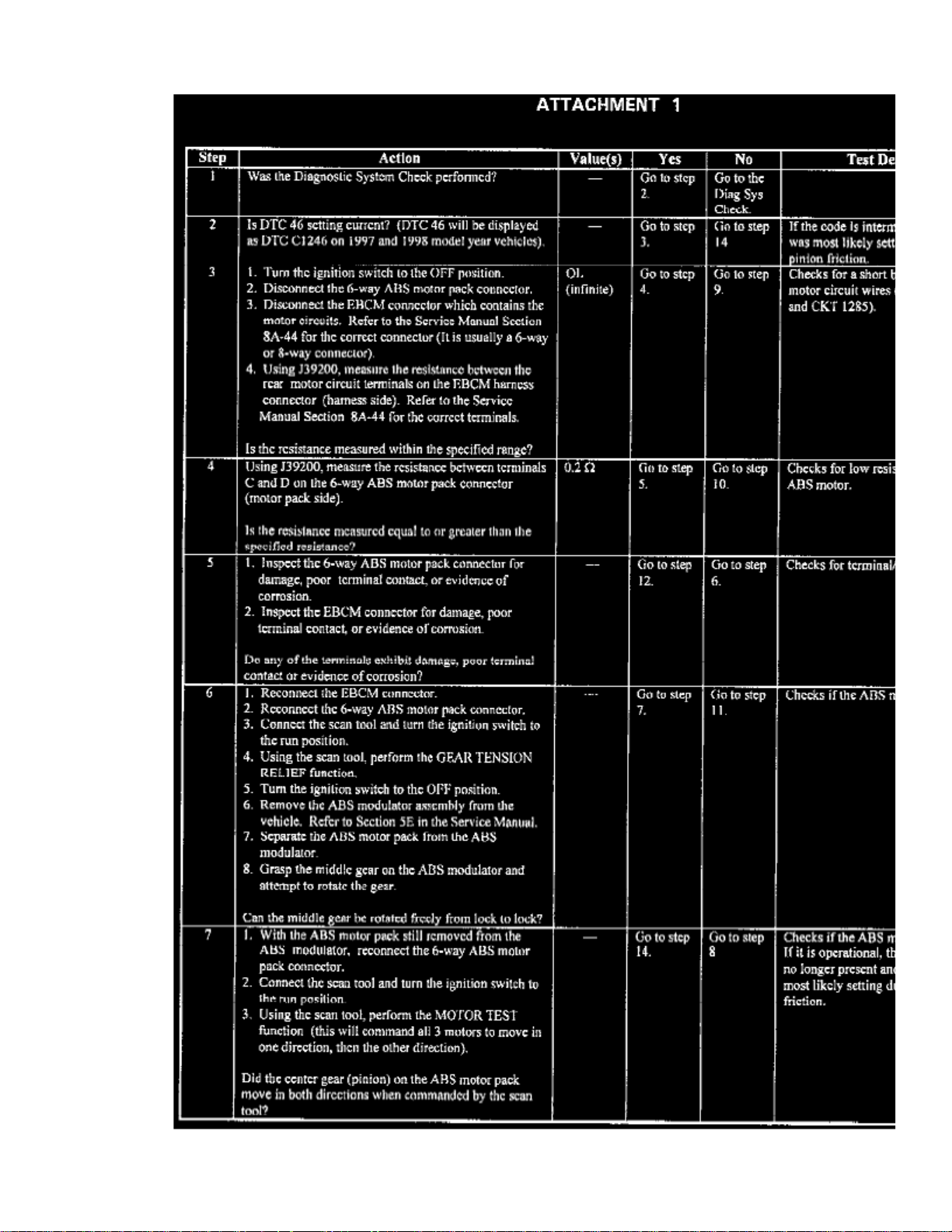
Follow the included procedure (Attachments 1 and 2) for diagnosis. This condition may correct itself before the owner is able to bring the vehicle in forservice. Therefore, if DTC 46 is set in history, and is not currently setting, the included procedure will instruct you to replace the center ABS motorpinion. The new pinion has a Teflon insert which reduces friction between the pinion and motor armature shaft.
Pinion Replacement
If the included procedure instructs you to replace the center ABS motor pinion, use P/N 18029776. Please note that the new pinion is a directreplacement part which requires no modifications to the motor shaft. Follow the pinion replacement procedure included with the new pinion. Completemotor pack replacement is not required.
Parts Information
Parts are currently available from GMSPO.
Warranty Information
For vehicles repaired under warranty, use:
Labor Operation Labor Time
H2506 Use published labor
operation time.
Page 79

Page 80

> Relays and Modules > Relays and Modules - Brakes and Traction Control > Electronic Brake Control Module > Component Information > Technical Service Bulletins > All Technical Service Bulletins for Electronic Brake
Control Module: > 73-50-26 > Aug > 97 > Brakes - ABS Light ON, DTC 46 & 86 (C1246 & C1286)
Electronic Brake Control Module: All Technical Service BulletinsBrakes - ABS Light ON, DTC 46 & 86 (C1246 & C1286)
File In Section: 5 - Brakes
Bulletin No.: 73-50-26
Date: August, 1997
Subject: ABS Light On - DTC's 46 and 86 Set(Perform Diagnostic Procedure, Replace Center ABS Motor Pinion)
Models: 1991-97 Buick Skylark1992-97 Buick Regal1994-97 Buick Century1992-96 Chevrolet Beretta, Corsica, Lumina APV1992-97 Chevrolet Cavalier, Lumina,1993-97 Chevrolet Camaro1995-97 Chevrolet Monte Carlo1997
Chevrolet Malibu, Venture
1993-97 Geo Prizm1995-97 Geo Metro1996-97 Geo Tracker1991
Oldsmobile Calais
1992-96 Oldsmobile Cutlass Ciera1992-97 Oldsmobile Achieva, Cutlass Supreme, Silhouette1997
Oldsmobile Cutlass
1998 Oldsmobile Intrigue
1991-97 Pontiac Grand Am1992-94 Pontiac Sunbird1992-97 Pontiac Grand Prix, Trans Sport1993-97 Pontiac Firebird, Trans Am1995-97 Pontiac Sunfire
Condition
Some owners may comment that the ABS light is on with Diagnostic Trouble Codes (DTC's) 46 and 86 set (rear ABS channel will not move) as currentor history. (DTC's 46 and 86 will be displayed as C1246 and C1286 on 1997 and 1998 model year vehicles).
Cause
A condition exists where the ABS motor pack gear (pinion) will bind on the motor armature shaft causing the motor not to move when commanded bythe EBCM. This condition is aggravated by light corrosion between the pinion and shaft. Therefore, it may occur more frequently when the weather ishot and humid.
Important:
Other EBCM and ABS motor pack concerns can also cause this condition, but they are not as common as the above cause.
Correction
Page 81

> Relays and Modules > Relays and Modules - Brakes and Traction Control > Electronic Brake Control Module > Component Information > Technical Service Bulletins > All
Technical Service Bulletins for Electronic Brake Control Module: > 73-50-26 > Aug > 97 > Brakes - ABS Light ON, DTC 46 & 86 (C1246 & C1286) > Page 99
Cutlass Ciera V6-3100 3.1L MFI VIN M (1994)
Page 82
Page 83

> Relays and Modules > Relays and Modules - Brakes and Traction Control > Electronic Brake Control Module > Component Information > Technical Service Bulletins > All
Technical Service Bulletins for Electronic Brake Control Module: > 73-50-26 > Aug > 97 > Brakes - ABS Light ON, DTC 46 & 86 (C1246 & C1286) > Page 100
Cutlass Ciera V6-3100 3.1L MFI VIN M (1994)
Page 84

Follow the included procedure (Attachments 1 and 2) for diagnosis. This condition may correct itself before the owner is able to bring the vehicle in forservice. Therefore, if DTC 46 is set in history, and is not currently setting, the included procedure will instruct you to replace the center ABS motorpinion. The new pinion has a Teflon insert which reduces friction between the pinion and motor armature shaft.
Pinion Replacement
If the included procedure instructs you to replace the center ABS motor pinion, use P/N 18029776. Please note that the new pinion is a directreplacement part which requires no modifications to the motor shaft. Follow the pinion replacement procedure included with the new pinion. Completemotor pack replacement is not required.
Parts Information
Parts are currently available from GMSPO.
Warranty Information
For vehicles repaired under warranty, use:
Labor Operation Labor Time
H2506 Use published labor
operation time.
Page 85

Page 86

> Relays and Modules > Relays and Modules - Brakes and Traction Control > Electronic Brake Control Module > Component Information > Locations > Antilock Brake Module
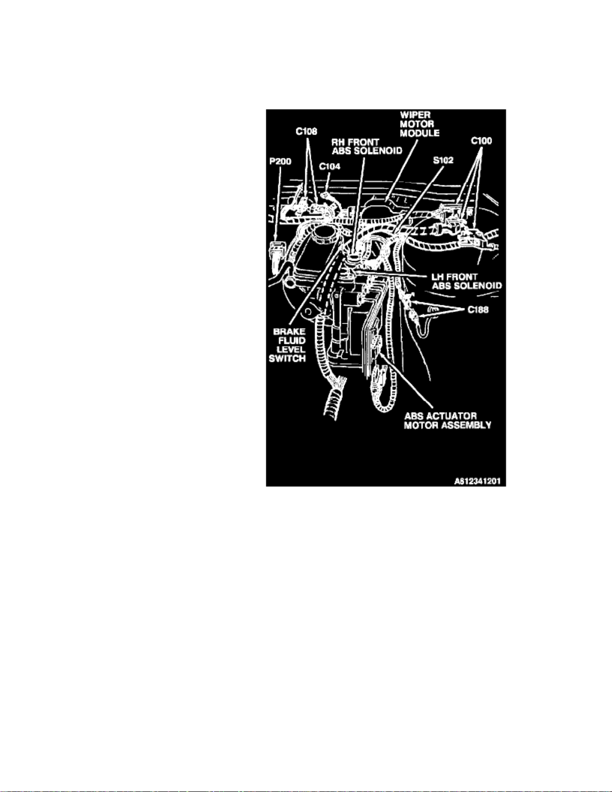
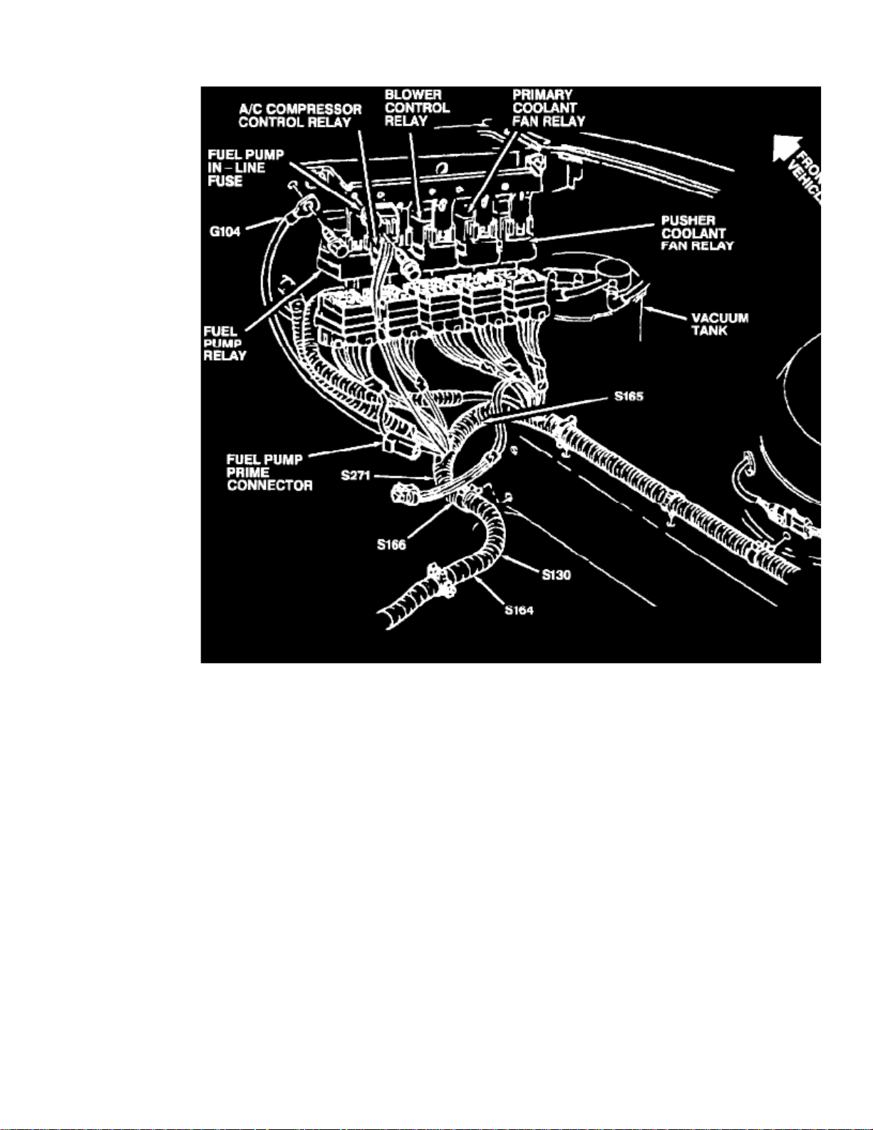
Electronic Brake Control Module: LocationsAntilock Brake Module
Fig. 1 TYPICAL ABS Components
Refer to for system component locations.Fig. 1
Page 87

Page 88

> Relays and Modules > Relays and Modules - Brakes and Traction Control > Electronic Brake Control Module > Component Information > Locations > Antilock Brake Module > Page 103
Behind RH Side Of I/P
Page 89

Page 90
> Relays and Modules > Relays and Modules - Brakes and Traction Control > Electronic Brake Control Module > Component Information > Diagrams > EBCM 2 Pin Connector
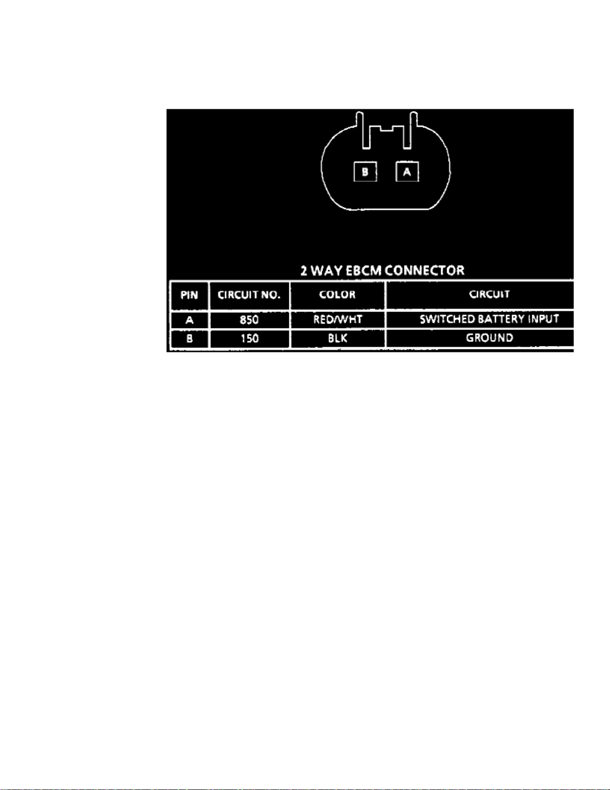
Electronic Brake Control Module: DiagramsEBCM 2 Pin Connector
Fig. 31 EBCM 2-pin Connector Face View.
When performing diagnostic procedures refer to for EBCM connector terminal identification.Fig. 31
Page 91

Page 92
> Relays and Modules > Relays and Modules - Brakes and Traction Control > Electronic Brake Control Module > Component Information > Diagrams > EBCM 2 Pin Connector > Page 106
Electronic Brake Control Module (EBCM)
Page 93

Page 94
> Relays and Modules > Relays and Modules - Brakes and Traction Control > Electronic Brake Control Module > Component Information > Diagrams > EBCM 2 Pin Connector > Page 107
Electronic Brake Control Module: DiagramsPinout Description
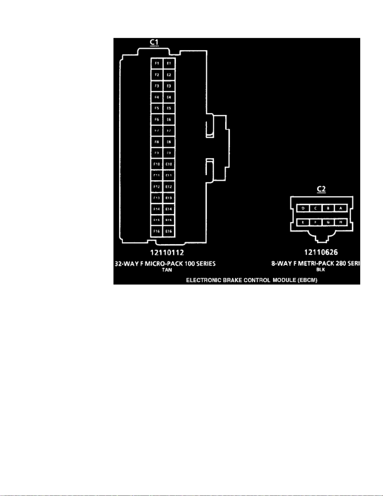
Electronic Brake Control Module (EBCM) (Part 1 Of 2)
Electronic Brake Control Module (EBCM) (Part 2 Of 2)
Page 95

Page 96

> Relays and Modules > Relays and Modules - Brakes and Traction Control > Electronic Brake Control Module > Component Information > Diagrams > Page 108
Electronic Brake Control Module: Description and Operation
DESCRIPTION
The ABS system is controlled by a microprocessor based Electronic Brake Control Module (EBCM). Inputs to the system include four wheelspeed sensors, brakes, ignition switch and unswitched battery voltage. Outputs include three bi-directional motor controls, three lamp controls, twosolenoid controls and the system enable relay. A serial data line, located in terminal 9 of the Data Link Connector (DLC), is provided for servicediagnostic tools and assembly plant testing.
The EBCM monitors the speed of each wheel. If any wheel begins to approach lock-up and the brake switch is on, the EBCM controls the motorsand solenoids to reduce brake pressure to the wheel approaching lock-up. Once the wheel regains traction, brake pressure is increased until wheelbegins to approach lock-up. This cycle repeats until either vehicle comes to a stop, the brake is released or no wheels approach lock-up.Additionally, the EBCM monitors itself, each input and each output for proper operation. If any system fault is detected, the EBCM will store aDTC in nonvolatile memory.
On a EBTCM, the ABS portion of the module operates the same as a EBCM. A EBTCM is used if the vehicle is equipped with either theEnhanced Traction System (ETS) or Traction Control System (TCS). The ETS or TCS portion of the EBTCM monitors wheel spin slip throughthe drive wheels speed sensors. If the wheels begin to slip, the EBTCM determines the desired wheel torque needed to minimize wheel slip. Thisinformation is sent to the PCM through the Serial data link. On models equipped w/ETS, the PCM controls engine torque by ignition retard andtransmission shifts. On models equipped w/TCS, the PCM controls engine torque by ignition retard, transmission shifts and applies brakes severaltimes until the vehicle regains traction. Once the vehicle regains traction, brake pressure is decreased and engine torque reduction is no longerrequested. This cycle repeats until traction control is no longer necessary.
Page 97

Page 98

> Relays and Modules > Relays and Modules - Brakes and Traction Control > Electronic Brake Control Module > Component Information > Diagrams > Page 109
Electronic Brake Control Module: Service and Repair
Fig. 800 EBCM Assembly Removal.
Fig.800
1. Disconnect EBCM electrical connectors, .2. Remove ECU to dash panel attaching screws, then the ECU from dash panel.3. Reverse procedure to install, noting the following:
a. Ensure plastic grommets, if equipped, are located properly.b. Bleed brake system as described under . See: Brakes and Traction Control/Brake BleedingBrake System Bleed
Page 99

Page 100
> Relays and Modules > Relays and Modules - Cooling System > Radiator Cooling Fan Motor Relay > Component Information > Locations
 Loading...