


OKPOS
Optimus Service Manual

2
Contents
Before Using the Product
Read this rst
4
Safety Information
4
Information on Copyrights
5
Overview
What’s in the Box
6
System Overview
7
Front 7
Rear and I/O ports 8
Adjusting LCD Angle
9
Installation
Connecting Peripherals
10
Removing the I/O port cover 10
Removing the stand’s rear cover 11
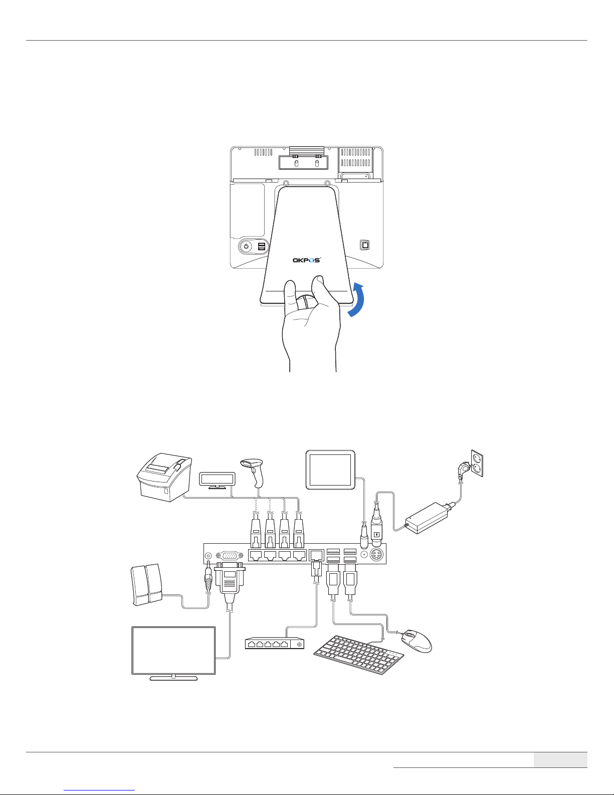
Connecting peripheral devices 11
Connecting the power cord 12
Replacing the I/O port cover 12
Replacing the stand’s rear cover 13
Installing Optional Devices
14
Card reader (IC & MSR) 14
VFD 16
LCD Customer Display 17
COM and SATA sub-board 20
Turning the SYSTEM On/O
21
Turning On 21
Turning O 21
System Disassembly
Disassembling the System
22
➊ Removing the cover 22
➋ Removing the COM and SATA
sub-board (optional) 25
➌ Removing the main board 26
➍ Removing the touch panel 27
➎ Removing the LCD module 28
Re-assembling the System
29
Components Replacement
30
Replacing the M.2 SSD 30
Replacing the memory module (RAM) 32
Replacing the CMOS battery 34
Replacing the SSD (optional) 35
Application Programs
Drivers
37
Utilities
37

3
Setting Up the Touch Screen
37
Setting Up the Card Reader
41
Running the setup program 41
Track setting 42
Sound setting 42
I/Button setting 43
Error code setting 43
Setting Up the VFD
44
Setting Up the LCD Customer Display
46
System Setup (BIOS)
48
Entering Setup 48
BIOS action keys 48
Main menu 49
Feature menu 49
Advanced menu 50
Chipset menu 53
Security menu 54
Boot menu 56
Save & Exit menu 57
HDD Recovery
58
System Boards
Main Board
59
Mainboard layout 59
I/O Ports of Main B/D 61
Jumper Settings 61
Headers and connectors 62
Touch Control B/D
66
Specications 66
Board Layout 67
COM and SATA Sub-board (optional)
68
Board Layout 68
Connector Descriptions 68
Cable Pin Assignment
LVDS Cable
70
MSR/IC Cable
71
COM1 Cable
71
COM2 Cable
72
COM3 Cable
72
COM4 Cable
73
Specications
General
74
Main Board
75

4
Before Using the Product
Read this rst
Before using your system, please read this Manual carefully, and keep it on hand for future
reference.
●
The contents of this manual may be changed without notice.
●
Depending on the system model and type, some parts of this manual may dier from the actual
product.
●
The basic drivers and utilities that come with your system are subject to change.
●
OKPOS assumes no responsibility for damages resulting from a use of the product that is not
approved by OKPOS, or failure to follow the precautions and instructions provided in this User
Manual.
●
As some of the storage space is used for the system OS and built-in software, the actual capacity
available is less than the storage capacity listed in the product specications. In addition, the
amount of available space may vary after you perform system OS and software updates.
Safety Information
Please observe the following safety instructions to protect your computer from damage and ensure
your personal safety.
●
Do not install the system in a location that is wet, damp, or near water. This may cause a re or an
electrical shock.
●
Only use the system in the specied power environment. The system may not work, and may
even cause a re, if it is used with a dierent power source or equipment, or in a country that has
dierent power specications.
●
Make sure the plug is not bent or crushed by a heavy object. A damaged plug can cause a re or an
electrical shock.
●
Do not modify or extend the power cable. Cable damage may cause an electrical shock or re.

Before Using the Product
| Information on Copyrights
5
●
Do not use a damaged power cord or plug, or a loose outlet. These may cause a re, short circuit,
or electrical shock.
●
Do not install the system in a location where it is likely to overheat or where it will be exposed to
direct sunlight. Ensure the system is kept a safe distance away from any heating device. Installation
in such locations could cause damage to the cabinet and the electronic components.
●
Do not drop or apply any strong shock to the system. This may cause damage to the system and
the SSD or HDD installed inside it.
●
Do not use a sharp-pointed object on the display or apply excessive pressure to the display. This
may cause damage to the touch LCD display.
●
Do not block or cover slots or openings in the system cabinet. These have been provided for
ventilation, to prevent the system from overheating.
●
Do not use this system on a bed, sofa, rug or other similar surface.
●
Never insert any object into the system through the cabinet openings, as they may touch
dangerous voltage points or short out parts, which could result in a re or electrical shock.
●
Never spill liquid of any kind on the product.
●
Unplug the system from the electrical power outlet before cleaning. Clean the system, using a
damp or dry cloth. Do not use abrasives, kerosene, benzene, thinner, hydrochloric acid, or hot
water, and do not use a tough sponge or a brush, as these may cause discoloration or deterioration
of the cabinet.
●
Use only a 3-wire grounding type plug to avoid electric shock and damages due to short circuits.
●
If you have to use an extension cord, make sure that the total amperage rating of all equipment
plugged into it does not exceed the amperage rating of the extension cord and only use a 3-wire
grounding extension cord with a 3-prong grounding plug and outlet.
Information on Copyrights
●
Copyright © 2018 OKPOS Co., Ltd.
●
This manual is protected under international copyright laws. No part of this manual may be
reproduced, distributed, translated, or transmitted in any form or by any means without the prior
written permission of OKPOS Co., Ltd.
●
OKPOS and Optimus are registered trademark of OKPOS Co., Ltd.
●
Windows 7/10 is a registered trademark of Microsoft.
●
All other trademarks and copyrights are the property of their respective owners.
6
Overview
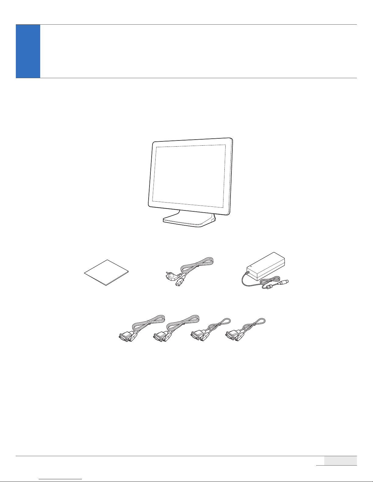
What’s in the Box
The package include the following items.
Optimus system
COM 1/2/3/4 cables(1.2 m x 2, 0.35 m x 2)
Quick Start Guide AdaptorPower cable
NOTE:
⦁
If any of the above is missing, please contact the customer center.
⦁
Only use devices with this system that have been supplied or approved by OKPOS. If you use a device supplied
by another provider that is not approved, your system may malfunction or not work.
⦁
The appearance and specications of the system and accessories may be changed without notice.
⦁
If you misplace one of the included components and want to purchase a new one, contact the customer center.
Overview
| System Overview
7
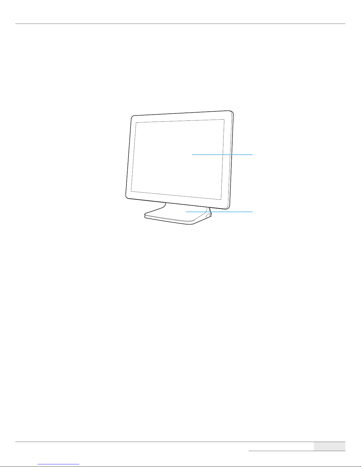
System Overview
Front
Touch display panel
(touch LCD)
Stand
Overview
| System Overview
8
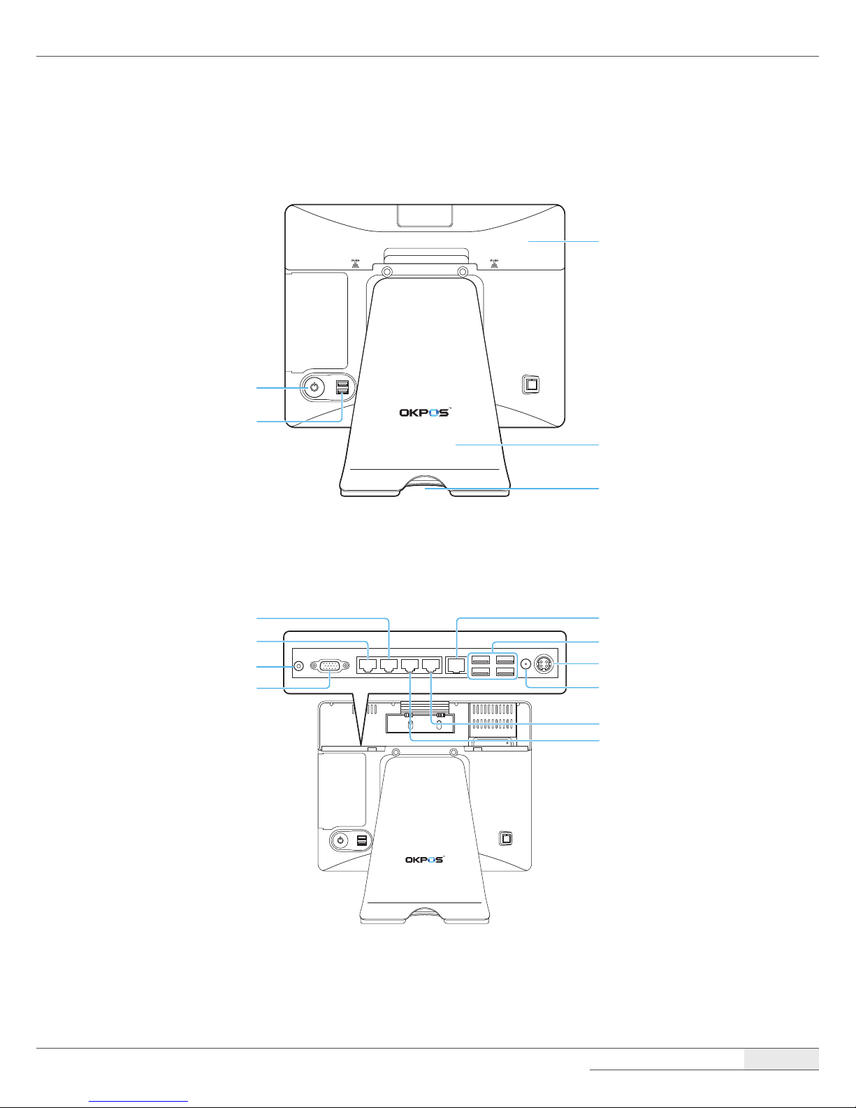
Rear and I/O ports
Stand rear cover
I/O port cover
Cable hole
Power button
Two USB ports
Power (12V DC-IN) jack
Power (12V DC-OUT) jack
COM4 port
COM3 port
Four USB ports
LAN port
Speaker jack
VGA port
COM1 port
COM2 port
Overview
| Adjusting LCD Angle
9
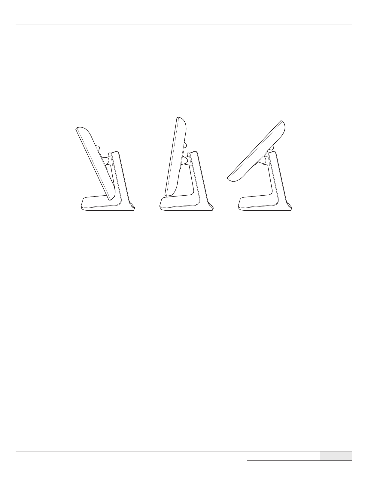
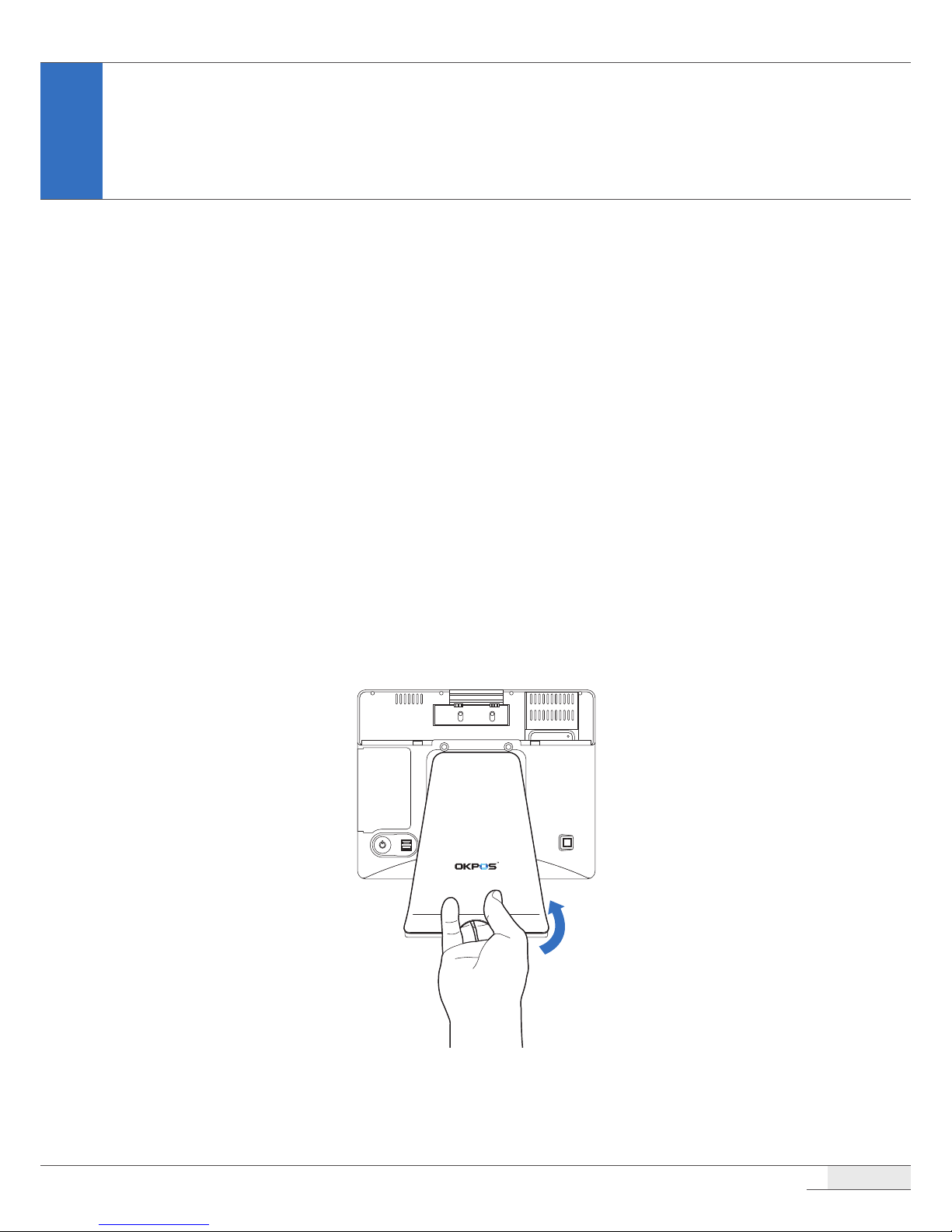
Adjusting LCD Angle
You can tilt the LCD to achieve the optimum viewing angle. The angle can be adjusted within 45
degrees up/down.
Adjust the tilt of the LCD for your convenience.
CAUTION:
⦁
Do not put sharp objects on the surface of the LCD, and never spray cleaner directly onto the display.
⦁
Do not pull the display beyond the maximum tilt angle, and do not apply excessive pressure to the display.
10
Installation
Connecting Peripherals
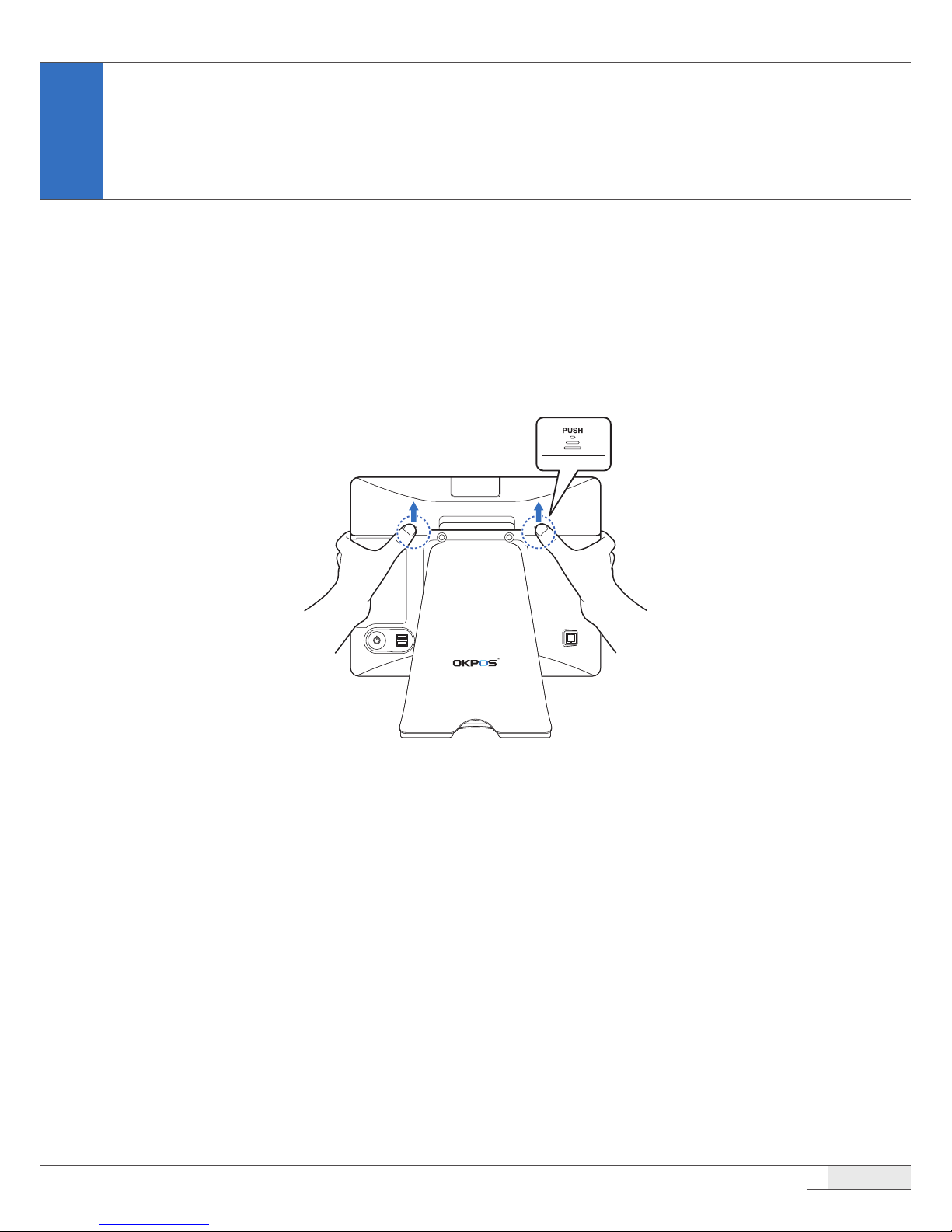
Removing the I/O port cover
Using your ngers, push and hold the two points marked PUSH on the I/O port cover, then slide the
cover up.
Installation
| Connecting Peripherals
11
Removing the stand’s rear cover
Hold the lower side of the stand’s rear cover and pull it away from the stand.
Connecting peripheral devices
Installation
| Connecting Peripherals
12
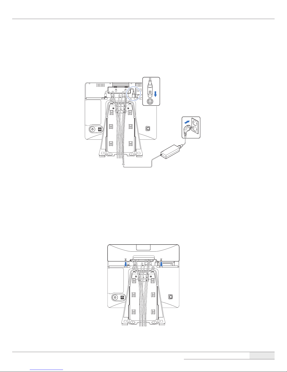
Connecting the power cord
Plug the power cord into the power jack on the I/O panel and then plug the other end of the power
cord into an appropriately grounded electrical outlet.
Replacing the I/O port cover
1.
Make sure that all of the connected cables are arranged through the cable hole position of the
I/O port cover so that they will not be pinched when you replace the cover.
2.
Align the I/O port cover, then rmly slide the I/O port cover down.
Installation
| Connecting Peripherals
13
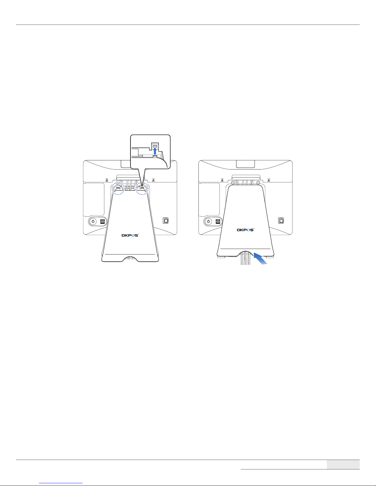
Replacing the stand’s rear cover
1.
Make sure that all cables are arranged inside the cable path of the stand so that they will not be
pinched when you close the stand’s rear cover.
2.
Align the two latch pins on the upper side of the cover with the stand latch holes, and press the
lower side of the cover rmly into place.
Installation
| Installing Optional Devices
14
Installing Optional Devices
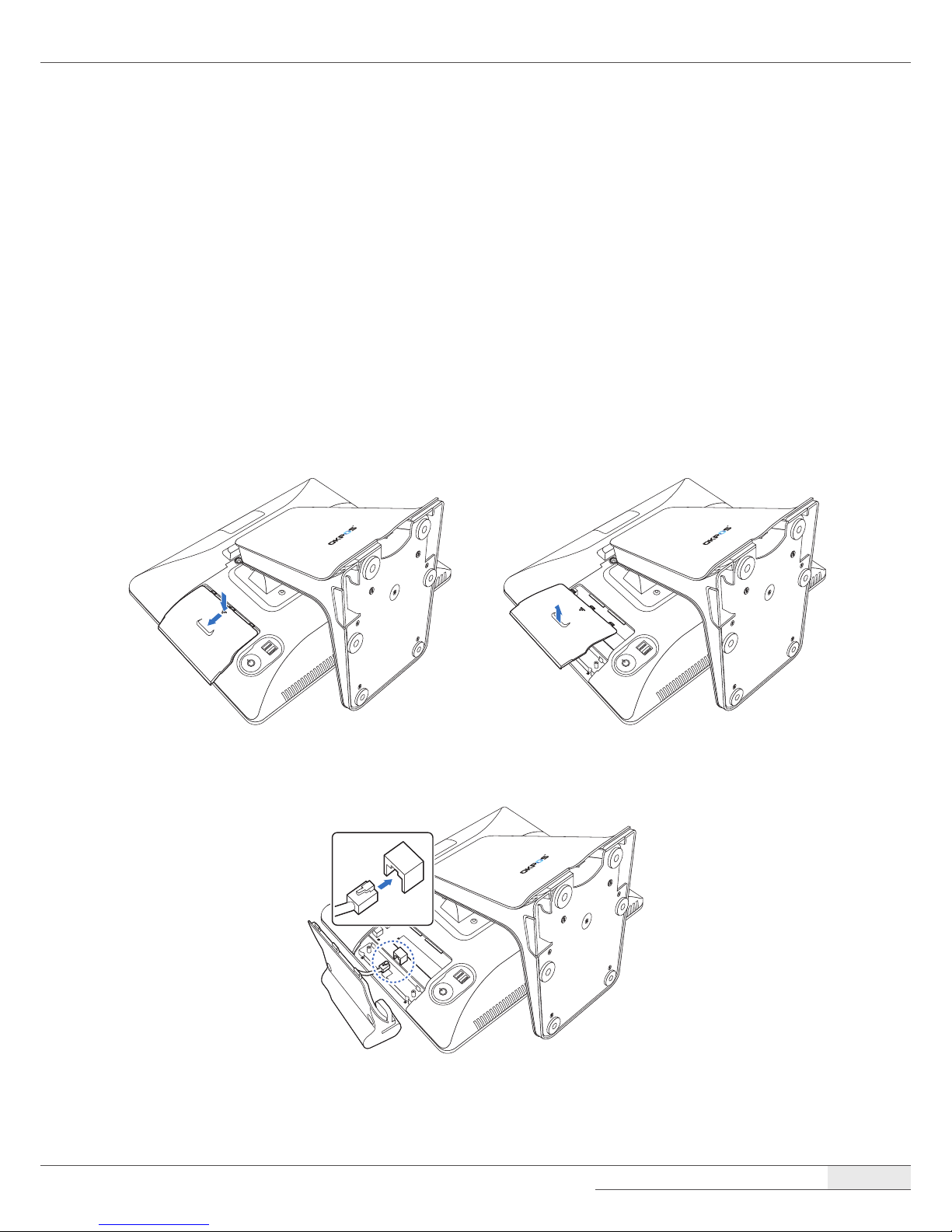
Card reader (IC & MSR)
Installing the card reader
To install the card reader, follow these steps:
1.
Place the touch LCD panel side down on a soft, at surface. (Be careful not to damage the touch
LCD panel.)
2.
To remove the dummy cover, press the marked point and slide the dummy cover slightly, and
then lift it up.
3.
Connect the RJ-45 cable of the card reader to the main board.
Installation
| Installing Optional Devices
15
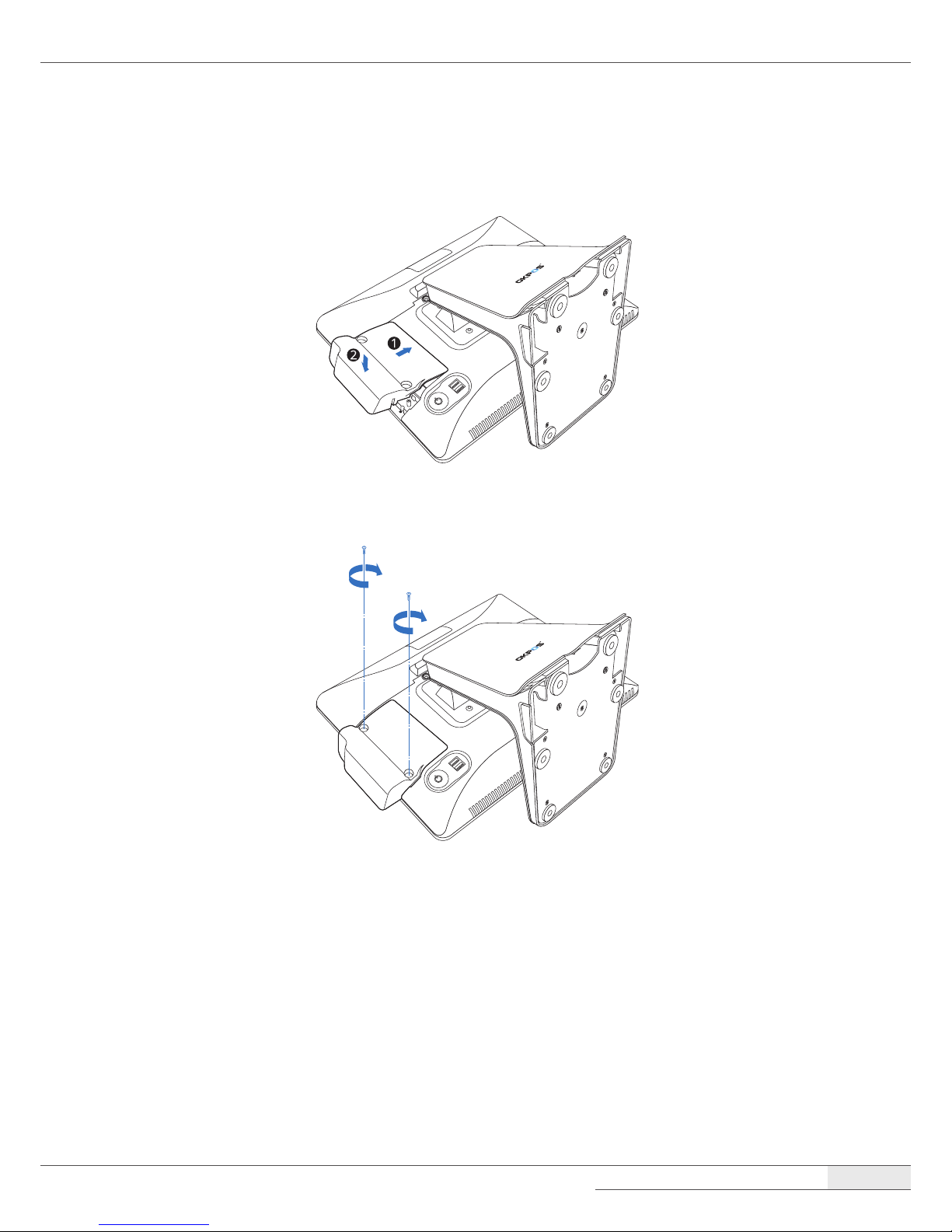
4.
Align the two latch pins on the card reader with the back cover holes and press the card reader
down rmly into place.
5.
Tighten the two screws.
Removing the card reader
You can remove the card reader by following the steps in the installation procedure in reverse order.
Installation
| Installing Optional Devices
16
VFD
Installing the VFD
To install the VFD, follow these steps:
1.
Remove the I/O port cover by following the instructions in “Removing the I/O port cover“ on
page 10.
2.
Detach the plate on the I/O port cover to make space for installing the VFD.
NOTE:
⦁
Completely remove the plate, ensuring that no sharp parts remain. There is the risk of injuring yourself if the
sharp edges are not completely removed.
3.
Place the VFD and tighten it with two thumbscrews.
Installation
| Installing Optional Devices
17
4.
Connect the RJ-45 cable of the VFD to the COM3 port.
5.
Replace the I/O port cover by following the instructions in “Replacing the I/O port cover“ on
page 12.
6.
After installing the VFD, change the BIOS setting by following the instructions in “Setting Up the
VFD“ on page 44.
Removing the VFD
You can remove the VFD by following the steps in the installation procedure in reverse order.
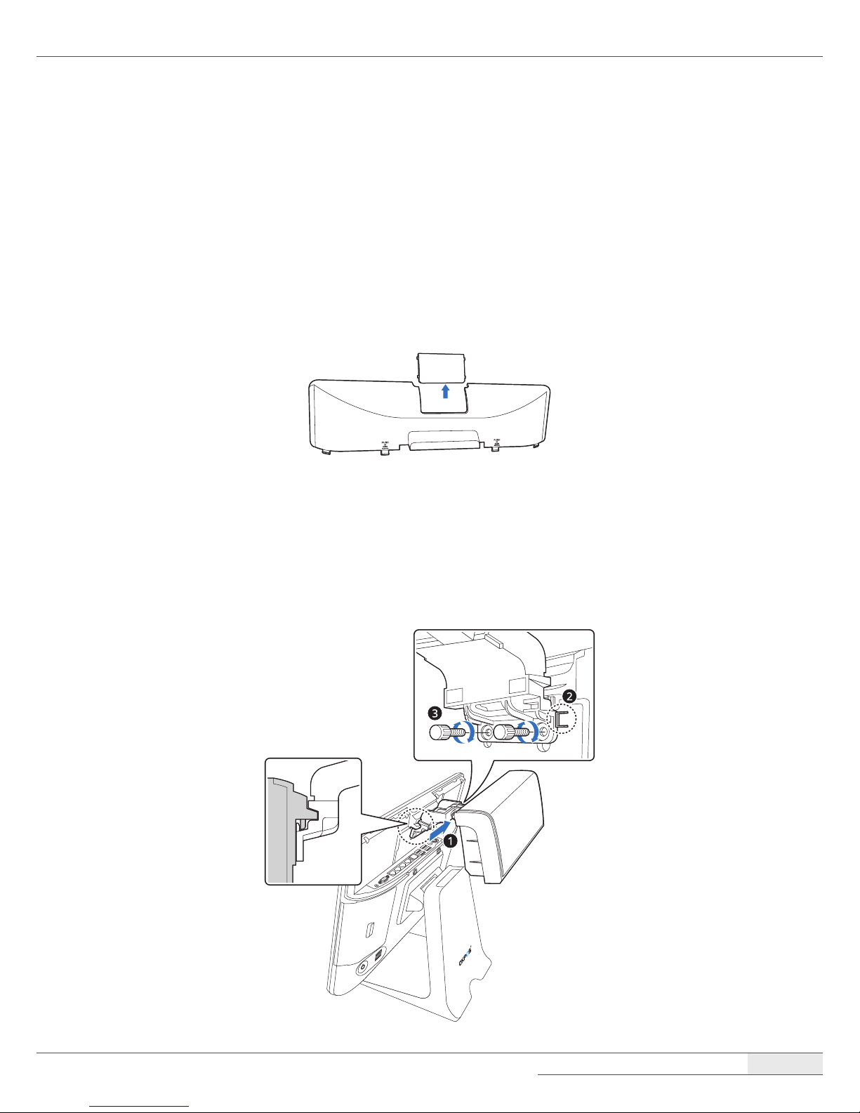
LCD Customer Display
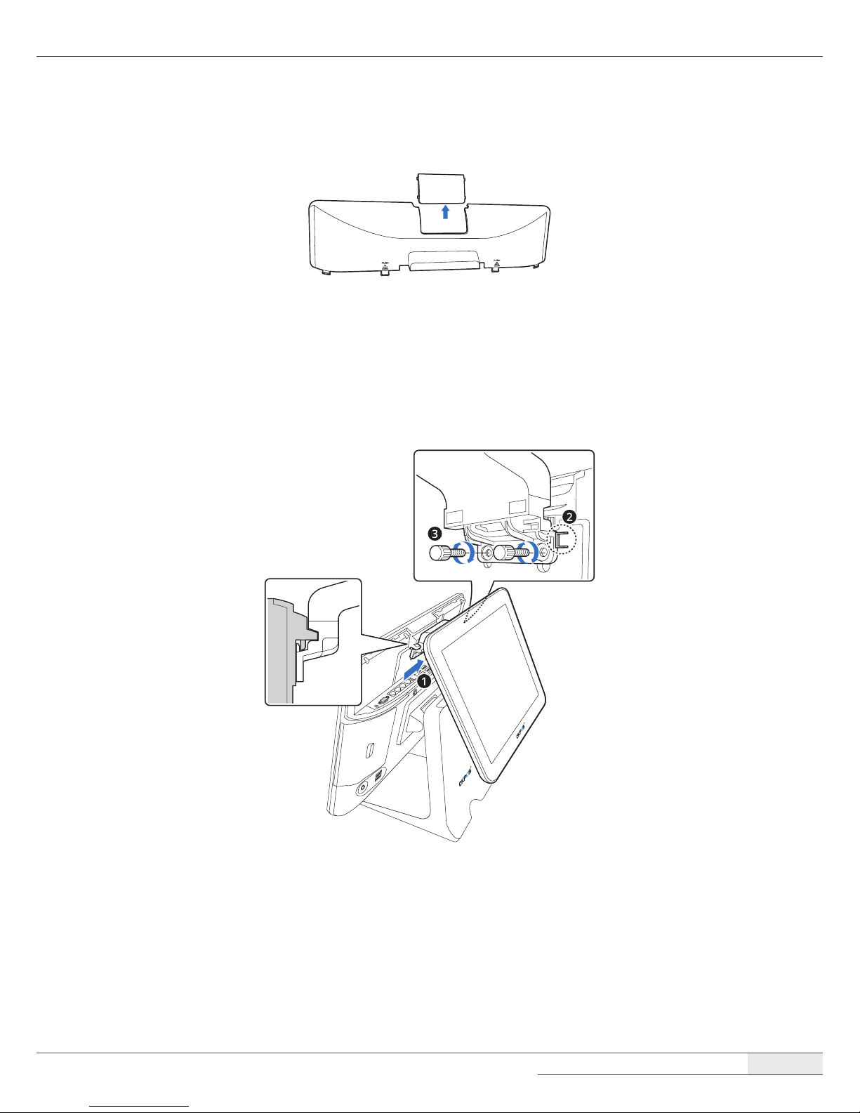
Installing the LCD Customer Display
To assemble the LCD customer display, follow these steps:
1.
Remove the I/O port cover by following the instructions in “Removing the I/O port cover“ on
page 10.
Installation
| Installing Optional Devices
18
2.
Detach the plate on the I/O port cover to make space for installing the LCD customer display.
NOTE:
⦁
Completely remove the plate, ensuring that no sharp parts remain. There is the risk of injuring yourself if the
sharp edges are not completely removed.
3.
Place the LCD customer display and tighten it with two thumbscrews.
Installation
| Installing Optional Devices
19
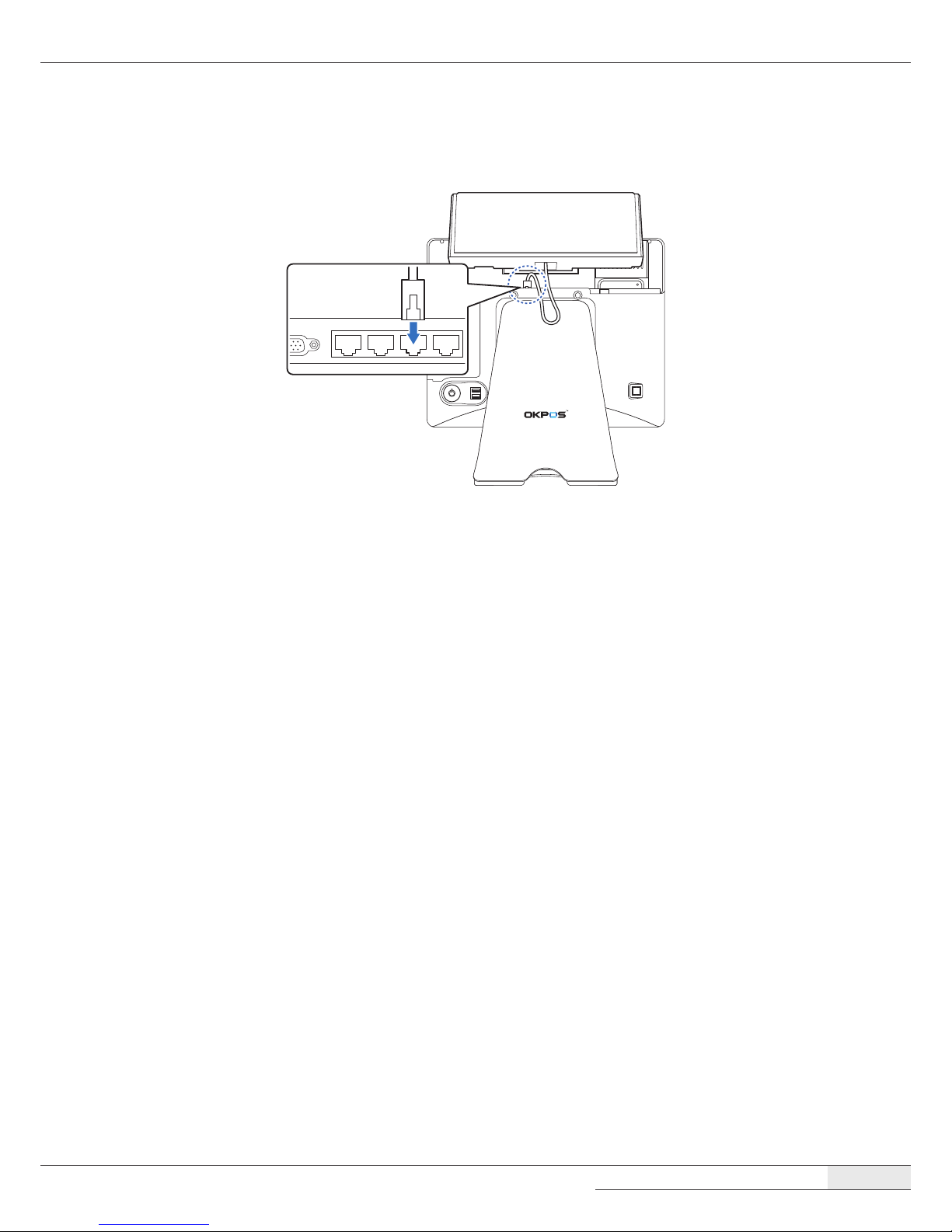
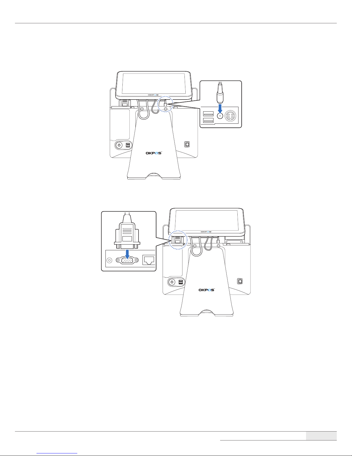
4.
Connect the power cable of the LCD customer display to the power (12V DC-OUT) jack.
5.
Connect the VGA cable of the LCD customer display to the VGA port.
6.
Replace the I/O port cover by following the instructions in “Replacing the I/O port cover“ on
page 12.
Removing the LCD Customer Display
You can remove the LCD customer display by following the steps in the installation procedure in
reverse order.
Installation
| Installing Optional Devices
20
COM and SATA sub-board
Installing the COM and SATA sub-board
To install the COM and SATA sub-board, follow these steps:
1.
Remove the system cover by following the instructions in “➊ Removing the cover“ on page 22.
2.
Connect the COM and SATA sub-board to the COM and SATA header on the main board, and
tighten the two screws.
3.
Replace the system cover by following the instructions for removal in reverse order.
Removing the COM and SATA sub-board
You can remove the COM and SATA sub-board by following the steps in the installation procedure in
reverse order.
Installation
| Turning the SYSTEM On/O
21
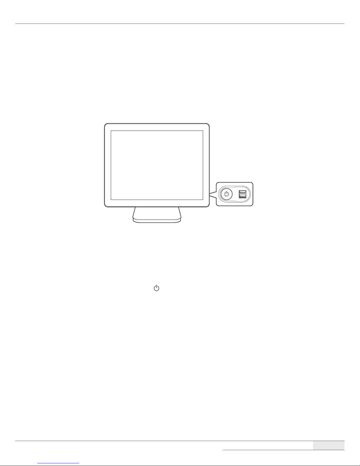
Turning the SYSTEM On/O
Turning On
1.
Turn on the power of the peripheral devices connected to the system.
2.
Press the power button on the lower right side of the back of the system.
Turning O
1.
Close all the applications currently running.
2.
Windows 7: Click Start ➜ Shut down.
Windows 10: Click Start ➜ Power ( ) ➜ Shut down.
NOTE:
⦁
You can also turn o the system by pressing the power button. After all of the programs close, your system will
be turned o.
If the system is operating abnormally, you can reboot the system by holding down the Power button until the
system turns o. Then, press the Power button again to boot back up.
22
Disassembling the System
➊ Removing the cover
To remove the system cover, follow these steps:
1.
Turn o the system and peripheral devices.
2.
Remove the I/O port cover by following the instructions in “Removing the I/O port cover“ on
page 10.
3.
Remove the stand’s rear cover by following the instructions in “Removing the stand’s rear cover“
on page 11.
4.
Remove the power cord and all cables from the system.
5.
Place the touch LCD panel side down on a soft, at surface. (Be careful not to damage the touch
LCD panel.)
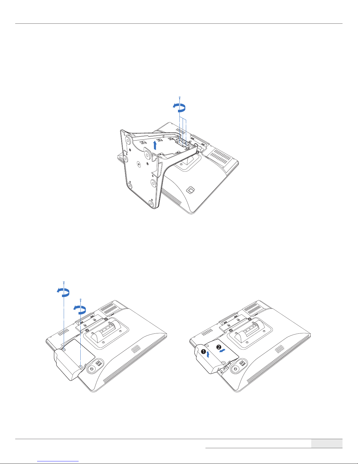
6.
Remove the screws and stand.
System Disassembly
System Disassembly
| Disassembling the System
23
NOTE:
⦁
This step is optional. If you do not need to disassemble the stand unit, go to step 7.
⦁
To disassemble the stand, remove the screws and separate the metal frame from the plastic case.
7.
Remove the card reader or dummy cover.
[When a card reader is installed]
① Remove two screws, hold one end of the card reader and lift up slightly, and pull it out.

System Disassembly
| Disassembling the System
24
② Remove the RJ-45 cable from the main board.
[When a dummy cover is installed]
To remove the dummy cover, hold one end of the dummy cover and lift up slightly, then pull it
out.

System Disassembly
| Disassembling the System
25
8.
Remove the eight screws, slide the back cover slightly, and lift up the back cover.
➋ Removing the COM and SATA sub-board (optional)
To remove the optional COM and SATA sub-board, follow these steps:
1.
Remove the screws xing the COM and SATA sub-board.
2.
Remove the COM and SATA sub-board from the main board, and separate it from the chassis.

System Disassembly
| Disassembling the System
26
➌ Removing the main board
To remove the main board, follow these steps:
1.
Remove all cables (LVDS, speaker, touch cable, etc.) from the main board.
2.
Remove the screws and separate the main board from the chassis.

System Disassembly
| Disassembling the System
27
➍ Removing the touch panel
To remove the touch panel, follow these steps:
1.
Remove the screws xing the touch panel module.
2.
Separate the touch panel module.

System Disassembly
| Disassembling the System
28
➎ Removing the LCD module
To remove the LCD module, follow these steps:
1.
Remove the screws xing the LCD module.
2.
Separate the LCD module.

System Disassembly
| Re-assembling the System
29
Re-assembling the System
You can assemble the system by following the steps in the disassembly procedure in reverse order.

System Disassembly
| Components Replacement
30
Components Replacement
Replacing the M.2 SSD
To replace the M.2 SSD, follow these steps:
1.
Turn o the system and peripheral devices.
2.
Remove the I/O port cover by following the instructions in “Removing the I/O port cover“ on
page 10.
3.
Remove the stand’s rear cover by following the instructions in “Removing the stand’s rear cover“
on page 11.
4.
Remove the power cord and all cables from the system.
5.
Place the touch LCD panel side down on a soft, at surface. (Be careful not to damage the touch
LCD panel.)
6.
Remove the card reader or dummy cover by following the instructions in “➊ Removing the
cover“ on page 22.
7.
Remove the screw and the M.2 SSD card from the slot.

System Disassembly
| Components Replacement
31
8.
Install the new M.2 SSD card and tighten the screw.
9.
Replace the card reader or dummy cover.
10.
Connect the power cord and all cables to the system.
11.
Replace the I/O port cover by following the instructions in “Replacing the I/O port cover“ on
page 12.
12.
Replace the stand rear cover by following the instructions in “Replacing the stand’s rear cover“
on page 13.

System Disassembly
| Components Replacement
32
Replacing the memory module (RAM)
To replace the memory module, follow these steps:
1.
Remove the system cover by following the instructions in “➊ Removing the cover“ on page 22.
2.
Pull the clips on both sides of the memory slot outward to release the installed memory
module. One end of the memory module will pop up.
3.
Pull the memory module straight out from the memory slot.

System Disassembly
| Components Replacement
33
4.
Insert the new memory modules into the open slots at a 30-degree angle, and press down until
both clips engage and click into place.
5.
Replace the system cover by following the instructions for removal in reverse order.

System Disassembly
| Components Replacement
34
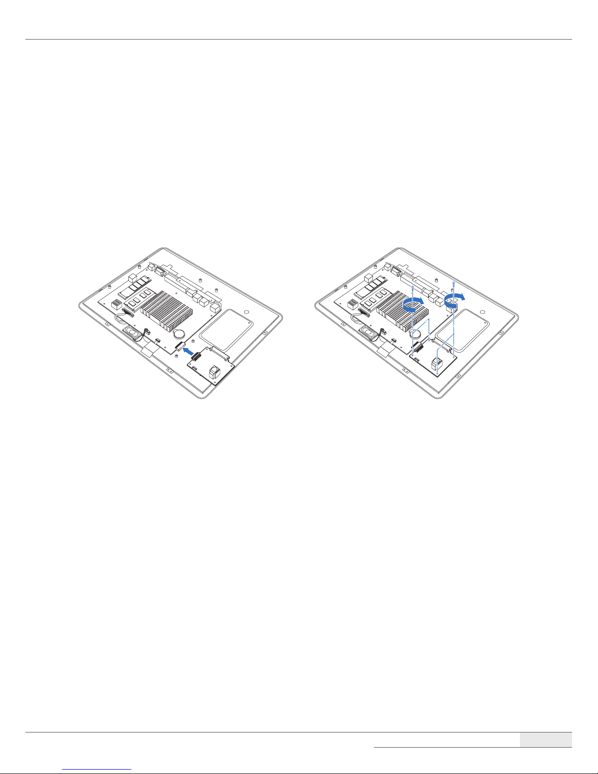
Replacing the CMOS battery
To replace the CMOS battery on the main board, follow these steps:
1.
Remove the system cover by following the instructions in “➊ Removing the cover“ on page 22.
2.
Locate the CMOS battery on the main board and gently press the retaining clip on the CMOS
battery socket.
3.
When one side of the CMOS battery pops up, grab on to the edge of the battery and pull it up
and out of the socket.
4.
Insert one side of the new battery into the socket and press it down until the clip engages and
clicks into place.

System Disassembly
| Components Replacement
35
5.
Replace the system cover by following the steps for removal in reverse order.
Replacing the SSD (optional)
To replace the optional SSD, follow these steps:
1.
Turn o the system and peripheral devices.
2.
Remove the I/O port cover by following the instructions in “Removing the I/O port cover“ on
page 10.
3.
Remove the stand rear cover by following the instructions in “Removing the stand’s rear cover“
on page 11.
4.
Remove the power cord and all cables from the system.
5.
Unscrew the thumbscrew and pull out the SSD module by holding the thumbscrew.

System Disassembly
| Components Replacement
36
6.
Replace the SSD.
7.
Insert the SSD module into the slot and tighten the thumbscrew.
8.
Connect the power cord and all cables to the system.
9.
Replace the I/O port cover by following the instructions in “Replacing the I/O port cover“ on
page 12.
10.
Replace the stand’s rear cover by following the instructions in “Replacing the stand’s rear cover“
on page 13.

37
Drivers
All drivers are located in D:\OKPOS\DRIVER.
All drivers are pre-installed on your system. If you need to install a driver, you can install it using the
driver installation les, which can be found in these folders.
Windows 7 Drivers Windows 8 & 10 drivers
or
Utilities
All utilities are installed in D:\OKPOS\Utility\MSR.
All utilities are pre-installed on your system. If you need to install a utility, you can install it using the
utility installation les, which can be found in these folders.
Setting Up the Touch Screen
If the touch point is not correct, close all programs and run the calibration program to calibrate your
touch screen.
CAUTION:
⦁
Do not use an object with a sharp point such as a ballpoint pen to calibrate the touch screen. This may cause
damage to the touch screen.
To calibrate the touch screen, please follow these steps:
Application Programs

Application Programs
| Setting Up the Touch Screen
38
[Windows 7]
1.
Turn on your system.
2.
Select Start ➜ Control Panel ➜ Tablet PC Settings.
➊
➋
➌
3.
When the Tablet PC Settings screen appears, click Calibrate in the Display tab.

Application Programs
| Setting Up the Touch Screen
39
4.
Calibrate your touch screen by following the on-screen instructions.
[Windows 10]
1.
Turn on your system.
2.
Select Start ➜ Control Panel ➜ Tablet PC Settings.
➊
➋
➌

Application Programs
| Setting Up the Touch Screen
40
3.
When the Tablet PC Settings screen appears, click Calibrate in the Display tab.
4.
Calibrate your touch screen by following the on-screen instructions.

Application Programs
| Setting Up the Card Reader
41
Setting Up the Card Reader
After connecting the card reader, run the MRMSetter program to setup the card reader.
Running the setup program
1.
Double-click the MRMSetter icon on the desktop.
➊
➋ ➍➌ ➏
➐
➎
➊
Read Data: Loads the previous setting values.
➋
Clear: Clears all settings and returns to the default settings.
➌
Read version: Displays the program version.
➍
Connect: Connects the card reader to the system.
➎
Disconnect: Disconnects the card reader from the system.
➏
Exit: Closes the MRM Setter program.
➐
: Closes the MRM Setter program.
2.
Click Connect.
3.
Select all settings for your card reader.
4.
Click Write Data and check the WRITE OK! message.
5.
Click Exit.

Application Programs
| Setting Up the Card Reader
42
Track setting
You can set the track.
1.
Select the track, input Start Code and End Code, and select Enter.
2.
Click Write Data and check the WRITE OK! message.
Sound setting
You can set the alarm for the card reading failure.
1.
Click the ON button for Sound.
2.
Click Write Data and conrm that the WRITE OK! message appears.

Application Programs
| Setting Up the Card Reader
43
I/Button setting
You can set the I/Button.
1.
Select I/Button and Enter.
2.
Click Write Data and check the message.
3.
If there is no error, click WRITE OK!
Error code setting
You can set the Error Code.
1.
Click the ON button for Error.
2.
Click Write Data and check the message.
3.
If there is no error, click WRITE OK!

Application Programs
| Setting Up the VFD
44
Setting Up the VFD
To setup the VFD, please follow these steps:
1.
After powering on the system, press [Del] to enter the System Setup screen.
2.
Go to the Advanced menu.
3.
Select Super IO Conguration.
4.
Select Serial Port 3 Conguration.
Aptio Setup Utility - Copyright (C) 2017 American Megatrands, Inc.
Advanced
Super IO Configuration
Super IO Chip
▶ SerialPort1Configuration
▶ SerialPort2Configuration
▶ SerialPort3Configuration
▶ SerialPort4Configuration
▶ SerialPort5Configuration
▶ SerialPort6Configuration
SetParametersofSerialPort3
🠖🠔
: Select Screen
🠕🠗
: Select Item
Enter : Select
+/- : Change Opt.
F1 : General Help
F2:PreviousValues
F9 : Optimized Defaults
F10 : Save & Exit
F12:PrintScreen
ESC : Exit
Version2.17.1246.Copyright(C)2017AmericanMegatrands,Inc.

Application Programs
| Setting Up the VFD
45
5.
Select Serial Port Voltage and choose +5V from the option list.
Aptio Setup Utility - Copyright (C) 2017 American Megatrands, Inc.
Advanced
SerialPort3Configuration
SerialPort [Enabled]
SerialPortVoltage [RI#]
DeviceSettings IO=3E8h;IRQ=6;
ChangeSettings [Auto]
SelectSerialPortVoltage
🠖🠔
: Select Screen
🠕🠗
: Select Item
Enter : Select
+/- : Change Opt.
F1 : General Help
F2:PreviousValues
F9 : Optimized Defaults
F10 : Save & Exit
F12:PrintScreen
ESC : Exit
Version2.17.1246.Copyright(C)2017AmericanMegatrands,Inc.
RI#
+5V
+12V
SerialPortVoltage
6.
Press [F10] to save the settings and exit the System Setup program.
7.
When the Save & Exit screen pops up, select Yes and press the [Enter] key.

Application Programs
| Setting Up the LCD Customer Display
46
Setting Up the LCD Customer Display
To set up the LCD Customer Display, please follow these steps:
1.
Turn on your system.
2.
Click Intel® HD Graphics on the task bar and select Graphics Properties….
➊
➋
3.
When the Intel® HD Graphics Control Panel screen appears, select Display.
4.
When the Display screen appears, click ( ) and select Multiple Displays.
➊
➋

Application Programs
| Setting Up the LCD Customer Display
47
5.
Choose the display mode in the Select Display Mode menu. After nishing the other settings,
click Apply.
6.
To keep the changes you have made to the settings, click Yes.

Application Programs
| System Setup (BIOS)
48
System Setup (BIOS)
For System Set up, setup only the items that you need. Note that incorrect settings of Setup items
could result in a system malfunction.
Entering Setup
After powering on the system, press [Del] to enter the System Setup screen.
BIOS action keys
Function key Command Description
🠖🠔
Select Screen Select the menu
🠕🠗
Select Item Select the item
Enter Select Shows the sub menu
+/
-
Change Opt. Selects the next value within a menu
F1 General Help Shows the help screen
F2 Previous Values Return to previous value
F9 Optimized Defaults Saves default setting
F10 Save & Exit Saves changes and reboots the computer.
ESC Exit Leaves a sub-menu to return to the previous menu or
exits the BIOS setup while saving changes.

Application Programs
| System Setup (BIOS)
49
Main menu
This menu reports processor and BIOS information, and is for conguring the system date and time.
Features Options Description
BIOS Information No options Displays the BIOS information.
CPU Conguration No options Displays the processor conguration.
System Date Month, day, and year Species the current date.
System Time Hour, minute, and
second
Species the current time.
Access Level No options Displays your current access level.
If you enter the system with a user password, it will
display User. If no password is set or you enter the
system with an administrator password, this item will
display Administrator.
Feature menu
You can congure other features.
Features Options Description
Other Features
⮩
OS Selection
●
Windows 7
●
Windows 8.X
●
Android
Select OS of your system.
⮩
Flash Write Protection
●
Enabled
●
Disabled
Enables or disables BIOS SPI region read/write
protection.
⮩
Launch PXE OpROM
●
Enabled
●
Disabled
Enables or disables onboard LAN boot option
ROM.
⮩
Onboard LAN Control
●
Enabled
●
Disabled
Enables or disables the onboard LAN controller.
BIOS Update Utility
⮩
Update BIOS You can update the BIOS using the USB ash
disk that contains the BIOS update les.

Application Programs
| System Setup (BIOS)
50
Advanced menu
This menu is for setting advanced features that are available through the chipset.
Features Options Description
ACPI Settings
⮩
Enable Hibernation
●
Enabled
●
Disabled
Enables or disables the system’s ability to
Hibernate (OS/S4 Sleep State). This option may
be not eective with some OS.
⮩
ACPI Sleep State
●
Suspend Disabled
●
S3 (Suspend to
RAM)
Select the highest ACPI sleep state the system
will enter when the SUSPEND button is pressed.
Super IO Conguration
⮩
Serial Port 1/2/3/4/5/6
Conguration
Set the parameters of Serial Port 1/2/3/4/5/6.
- Serial Port
●
Enabled
●
Disabled
Enables or disables the Serial Port (COM).
- Serial Port Voltage
●
RI#
●
+5V
●
+12V
Select the serial port voltage.
- Device Settings No options Displays the resource assigned to the serial
port.
- Change Settings
●
Auto
●
IO=3F8h; IRQ=4;
●
IO=3F8h;
IRQ=3,4,5,6,7,10,11;
●
IO=2F8h;
IRQ=3,4,5,6,7,10,11;
●
IO=3E8h;
IRQ=3,4,5,6,7,10,11;
●
IO=2E8h;
IRQ=3,4,5,6,7,10,11;
Select the settings for the serial port.
H/W Monitor
⮩
PC Health Status No options Displays the temperature, fan speed, and
voltage.

Application Programs
| System Setup (BIOS)
51
Features Options Description
Power Button Control
⮩
Restore AC Power
Loss
●
Power O
●
Power On
●
Last State
Determines the mode of operation when your
system resumes after an AC power loss.
CPU Conguration
⮩
Socket 0 CPU
Information
No options Displays the CPU information of the specied
socket.
⮩
Limit CPUID
Maximum
●
Enabled
●
Disabled
Disabled for Windows XP.
⮩
Execute Disable Bit
●
Enabled
●
Disabled
Enables or disables Execute Disable Technology.
⮩
Intel Virtualization
Technology
●
Enabled
●
Disabled
Enables or disables Virtualization Technology.
Virtualization allows a platform to run multiple
operating systems and applications. This item
will be displayed only when the CPU supports
this feature.
SATA Conguration
⮩
SATA Controller
●
Enabled
●
Disabled
Enables or disables the SATA controller.
⮩
SATA Speed Support
●
Gen1
●
Gen2
Select the SATA speed. (Gen1 is 1.5 Gbit/s and
Gen2 is 3 Gbit/s.)
⮩
SATA Controller Mode
●
IDE Mode
●
AHCI Mode
Set the mode of your SATA ports.
⮩
SATA Port 1
●
Enabled
●
Disabled
Enables or disables SATA Port 1.
⮩
SATA Port 2
●
Enabled
●
Disabled
Enables or disables SATA Port 2.

Application Programs
| System Setup (BIOS)
52
Features Options Description
USB Conguration
⮩
USB Devices
- Legacy USB Support
●
Enabled
●
Disabled
Enables or disables the support for USB devices
on legacy operating systems.
- XHCI Hand-o
●
Enabled
●
Disabled
This is a workaround for OSes that lack XHCI
hand-o support. The XHCI ownership change
should be claimed by the XHCI driver.
- EHCI Hand-o
●
Enabled
●
Disabled
This is a workaround for OSes that lack EHCI
hand-o support. The EHCI ownership change
should be claimed by the EHCI driver.
- USB Mass Storage
Driver Support
●
Enabled
●
Disabled
Enables or disables the USB mass storage driver
support.
⮩
USB hardware delays
and time-outs
- USB transfer time-
out
●
1 sec
●
5 sec
●
10 sec
●
20 sec
Set the time-out value for control, bulk, and
Interrupt transfers.
- Device reset time-
out
●
10 sec
●
20 sec
●
30 sec
●
40 sec
Set the device reset time-out value.
- Device power-up
delay
●
Auto
●
Manual
Set the device power-up delay value.
- Device power-up
delay in seconds
Input box Input the value of device power-up delay. Delay
range is 1~40 seconds, and can be adjusted in
one second increments.
Security Conguration
⮩
Intel(R) TXE
Conguration
- TXE
●
Enabled
●
Disabled
Enables or disables Intel TXE (Trusted Execution
Engine) for security.

Application Programs
| System Setup (BIOS)
53
Chipset menu
You can change the values for the chipset to optimize system performance.
Features Options Description
North Bridge
⮩
Graphics
Conguration
- DVMT Pre-Allocated
●
64 MB
●
128 MB
●
256 MB
●
512 MB
Select the xed amount of system memory
allocated to the integrated graphics device
video. Intel DVMT allows additional memory to
be allocated for graphics usage based on an
application’s need. Once the application is closed,
the memory that was allocated for graphics
usage is then released and made available for
system use.
- DVMT Total Gfx
Mem
●
128 MB
●
256 MB
●
Max
Select the total amount of system memory
allocated to the integrated graphics device video.
- Aperture Size
●
128 MB
●
256 MB
●
512 MB
Select the aperture memory size of the system
memory.
- GTT Size
●
1 MB
●
2 MB
Select the GTT memory size of the system
memory.
- Primary IGFX Boot
Display
●
VGA + LVDS
●
VGA Only
●
LVDS Only
Select the video device used when the system
boots.
- LCD Panel Type
●
Auto
●
640x480 LVDS
…
●
1920x1200 LVDS
Select the LCD panel type.
- Panel Channel
●
Single Channel
●
Dual Channel
Select the LCD panel channel.
- Panel Color Depth
●
18 bit
●
24 bit
Select the LCD panel color depth.
⮩
Memory
Conguration
No options Displays the memory conguration.

Application Programs
| System Setup (BIOS)
54
Features Options Description
South Bridge
⮩
Azalia HD Audio
- Audio Controller
●
Enabled
●
Disabled
Enables or disables the Azalia HD Audio
controller.
⮩
USB Conguration
- USB 2.0 (EHCI)
Support
Enables or disables USB 2.0 support.
- USB Port 1/2 Enables or disables the USB port 1/2.
- USB Hub 1/2 Enables or disables the USB hub 1/2.
Security menu
This menu is for setting passwords and security features.
Features Options Description
Administrator
Password
Species the administrator password.
User Password Species the user password.
HDD Security
Conguration
⮩
HDD0 : SATA SSD No options Displays the HDD security conguration for the
selected driver.
NOTE:
Setting up the password
1. Go to Administrator Password (or User Password), and then press the [Enter] key.
2. On the following screen, enter the password and then press the [Enter] key.
Create New Password

Application Programs
| System Setup (BIOS)
55
3. On the following screen, enter the same password again and press the [Enter] key.
Conrm New Password
4. This will complete the password setup.
Changing the password
1. Go to Administrator Password (or User Password) when you want to change the password, and then press
the [Enter] key.
2. On the following screen, enter the current password and then press [Enter] key.
Enter Current Password
3. On the following screen, enter a new password and press the [Enter] key.
Create New Password
4. On the following screen, enter the same new password again and press the [Enter] key.
Conrm New Password
5. This will complete the password change.
Deleting the password
1. Go to Administrator Password (or User Password) when you want to delete the password, and then press
[Enter] key.
2. On the following screen, enter the current password and then press the [Enter] key.
Enter Current Password

Application Programs
| System Setup (BIOS)
56
3. On the following screen, enter nothing and press the [Enter] key.
Create New Password
4. When you get a message that says “Clear Old Password, Continue?” select Yes and press the [Enter] key.
5. This will complete deletion of the password.
Boot menu
This menu is for setting the boot sequence.
Features Options Description
Boot Conguration
⮩
Setup Prompt
Timeout
Input box Input the number of seconds to wait for the
setup activation key.
⮩
Bootup NumLock
State
●
On
●
O
Turn the NumLock function of the keyboard on/
o when you turn on the system.
⮩
Customer Logo
●
Enabled
●
Disabled
Enables or disables displaying your logo when
you turn on the system.
Boot Option Priorities
⮩
Boot Option #1
Depending on
installed bootable
devices
Select the rst boot device from the available
devices.
⮩
Boot Option #2 Depending on
installed bootable
devices
Select the second boot device from the available
devices.
⮩
Hard Drive BBS
Priorities
Set the boot order of the legacy devices.
- Boot Option #1 Depending on
installed bootable
legacy devices
Select the rst boot device from the available
devices.

Application Programs
| System Setup (BIOS)
57
Save & Exit menu
This menu is for exiting the Setup program, saving changes, and loading and saving defaults.
Features Description
Save & Exit
⮩
Save Changes and Reset Exits and saves the changes to CMOS RAM.
⮩
Discard Changes and Reset Exits without saving any changes made in Setup.
⮩
Save Changes Saves the changes to CMOS RAM.
⮩
Discard Changes Discards changes without exiting Setup.
⮩
Restore Defaults Loads the default values for all the Setup options.
Boot Override After BIOS detects the currently connected devices, select the device
you want to boot from and press the [Enter] key, and then the
system will directly boot from the selected device.

Application Programs
| HDD Recovery
58
HDD Recovery
WARNING:
⦁
The hard disk recovery process erases all of the data and programs that you installed on your hard disk. After a
hard disk recovery, you must reinstall any software that was not originally installed at the factory.
⦁
Be sure to backup your own data before running the recovery process.
To recover the hard disk to factory settings, use the follow steps:
1. Connect the power cord, keyboard, and mouse to your system.
2. Press the power button.
3. When the "F11 to WinClon…" message appears on the screen, press [F11] at the upper side of the keyboard.
4. When the WinClon screen appears, select the desired option (“Restore to recent state” or “Restore to initial
state.”)
Restore to the most recent
state of Windows using a
backup le.
Restore to the factory
default state of Windows.
5. Enter the password (the password is “pos”) and press OK to continue the recovery.
6. The disk restoration procedure will start. Follow the on-screen instructions to recover your hard disk drive.

59
Main Board
Mainboard layout
1
17 16
2 3 4 5
18
6
7
8
9
10
11
12
13
14
15
System Boards

System Boards
| Main Board
60
1
System fan header
2
Realtek RTL 8111F LAN controller
3
ITE IT8766E-I super I/O controller
4
CMOS battery
5
COM and SATA connector
6
Clear CMOS jumper
7
Buzzer
8
USB 8 pins FPC connector for touch
9
Speaker header
10
CPU
11
LVDS header
12
Front panel header
13
USB ports
14
M.2 SATA2 2260/2280 SSD socket
15
Power button
16
Memory socket
17
Realtek Codec ALC662 audio controller
18
I/O ports

System Boards
| Main Board
61
I/O Ports of Main B/D
Pin Denition
1 +12V DC_IN
2 +12V DC_IN
3 GND
4 GND
DC-12V Input Connector
DC_IN1
1
2
4
+DC 12V
GND
3
R_USB
2_1
R_USB
2_2
DC_OUT1
LAN1 VGA1 PJ1RJ_COM1-4
DC-12V Output Jack (3.5 Ø, Max. 2A)
Jumper Settings
The illustration shows how to set up jumpers. When the jumper cap is placed on pins, the jumper is
"close", if not, that means the jumper is "open".
Pin opened Pin closed Pin1-2 closed
JP1: Clear CMOS Jumper
Placing the jumper on pin2-3, it allows user to restore the BIOS safe setting and the CMOS data.
Please carefully follow the procedures to avoid damaging the motherboard.
1
3
1
1
3
3
Pin 1-2 Closed: Normal(Default)
Pin 2-3 Closed: Clear CMOS

System Boards
| Main Board
62
※ Clear CMOS Procedures:
1. Remove AC power line.
2. Set the jumper to "Pin 2-3 close".
3. Wait for ve seconds.
4. Set the jumper to "Pin 1-2 close".
5. Power on the AC.
6. Load Optimal Defaults and save settings in CMOS.
Headers and connectors
Front panel header (F_PANEL1)
This 10-pin header includes HD LED, Power LED, Reset, PWR connection. It allows the user to connect
the system case’s front panel switch functions.
2
1 9
Pin Denition Pin Denition
1 HD LED+ 2 Power LED+
3 HD LED- 4 Power LED-
5 RESET- 6 PWR+
7 RESET+ 8 PWR-
9 N/C

System Boards
| Main Board
63
LVDS header (LVDS1)
This connector supports 18/24 bit dual-channel panels.
40 2
39 1
Pin Denition Pin Denition
1 +12V 2 +12V
3 +12V 4 +12V
5 +12V 6 GND
7 +3.3V 8 GND
9 VDD 10 VDD
11 N/C 12 N/C
13 LVDS_BKL_ADJ 14 N/C
15 LVDS_BKL_EN 16 GND
17 LVDS_A_DATA0- 18 LVDS_A_DATA0+
19 LVDS_A_DATA1- 20 LVDS_A_DATA1+
21 LVDS_A_DATA2- 22 LVDS_A_DATA2+
23 LVDS_A_CLK- 24 LVDS_A_CLK+
25 LVDS_A_DATA3- 26 LVDS_A_DATA3+
27 GND(Detect) 28 GND
29 LVDS_B_DATA0- 30 LVDS_B_DATA0+
31 LVDS_B_DATA1- 32 LVDS_B_DATA1+
33 LVDS_B_DATA2- 34 LVDS_B_DATA2+
35 LVDS_B_CLK- 36 LVDS_B_CLK+
37 LVDS_B_DATA3- 38 LVDS_B_DATA3+
39 GND 40 GND

System Boards
| Main Board
64
Speaker header (J_SPK1)
1 4
Pin Denition Pin Denition
1 SPK_R+ 2 SPK_L+
3 SPK_R- 4 SPK_L-
COM and SATA header (J_BD1)
20
2
19
1
Pin Denition Pin Denition
1 COM5_DCD# 2 +12V
3 COM5_RXD 4 COM5_DSR#
5 COM5_TXD 6 COM5_RTS#
7 COM5_DTR# 8 COM5_CTS#
9 COM5_RI# 10 +5V
11 GND 12 +5V
13 SATA_TX1+ 14 GND
15 SATA_TX1- 16 GND
17 SATA_RX1- 18 GND
19 SATA_RX1+ 20 GND
LPC header (J_LPC1)
Pin Denition Pin Denition
1 LFRAME# 2 LAD3
3 LAD2 4 LAD1
5 LAD0 6 GND
7 +3.3V 8 LCLK1
9 +3.3V
1
9

System Boards
| Main Board
65
System fan header (SYS_FAN1)
1
3
Pin Denition Pin Denition
1 GND 2 +12V
3 FAN Speed Detection

System Boards
| Touch Control B/D
66
Touch Control B/D
Specications
Features Description
Type Projected touch panel
Size 15 inches
Total thickness 2.0±0.3 mm
Outline of cover lens 343*273.8±0.3 mm
Outline of ITO sensor 319.33*245±0.3 mm
Viewing area 304.33*228.3±0.3 mm
Active area 307.33*231.3±0.3 mm
Interface USB
Number of touch points 10 points
Input voltage 5V
Response time 10ms
Pressure endurance value < 10g
Input Hand writing or capacitive pen
Transmittance > 85%
Surface Hardness
≥
7H

System Boards
| Touch Control B/D
67
Board Layout

System Boards
| COM and SATA Sub-board (optional)
68
COM and SATA Sub-board (optional)
Board Layout
RJ-45 COM port
SATA connector
Connector Descriptions
RJ-45 COM port
Drawer Kick-out Connector
Drawer Kick-out Connector Pin Assignments
Pin Number Signal Name Direction
1 Frame GND -
2 Drawer kick-out drive signal 1 Output
3 Drawer open/close signal Input
4 +24V -
5 Drawer kick-out drive signal 2 Output
6 Signal GND -
+24V is output through pin 4 when the power is turned on. However, pin 4 must be used only for the
drawer.

System Boards
| COM and SATA Sub-board (optional)
69
SATA connector
SATA Pin Assignment and Descriptions
Signal Segment Pin Assignment and Descriptions
Pin Number Function
S1 GND
S2 A+ (Dierential Signal Pair A)
S3 A – (Dierential Signal Pair A)
S4 GND
S5 B – (Dierential Signal Pair B)
S6 B+ (Dierential Signal Pair B)
S7 GND
Power Segment Pin Assignment and Descriptions
Pin Number Function
P1 Not Used (3.3V)
P2 Not Used (3.3V)
P3 DEVSLP
P4 GND
P5 GND
P6 GND
P7 5V pre-charge
P8 5V
P9 5V
P10 GND
P11 Reserved
P12 GND
P13 Not Used (12V pre-charge)
P14 Not Used (12V)
P15 Not Used (12V)

70
Cable Pin Assignment
LVDS Cable

Cable Pin Assignment
| MSR/IC Cable
71
MSR/IC Cable
COM1 Cable

Cable Pin Assignment
| COM2 Cable
72
COM2 Cable
COM3 Cable

Cable Pin Assignment
| COM4 Cable
73
COM4 Cable

74
General
Features Description
Model Name Optimus
CPU Intel® Celeron® J1900 (2.0 GHz) quad-core processor / fanless
Dimensions 414 x 251 x 361 mm (W x D x H)
Weight 8.4 kg
Power Adaptor Input: 100-240V, 50/60Hz, 1.5A
Output: 12V, 5.0A
Power button Push button type, on the lower-right side of the rear
Memory 2 GB standard DDR3L 1600 MT/s, Socket 1 x SODIMM (up to 8 GB)
Storage M.2 SSD64
2.5-inch SATA2 320 GB HDD or 64 GB/128 GB SSD (optional)
Display 15-inch, 1024 x 768 pixels
Touch Panel 10 points projective capacitive touch
Environment Operating Temperature: 0ºC to 60ºC
Storage Temperature: -20ºC to 80ºC
Operating Humidity: 20% to 90%
Storage Humidity: 10% to 90%
Speaker 1 x 1 W
USB 6 ea (USB 2.0, rear x 4, back x 2), 4 ea (internal, reserved for MSR,
SCR, i-Button, and touch controller)
Power 12 V DC-IN (4 pins connector),
12 V DC-OUT (for the second display)
OS (optional) Windows 7, 10, POSReady7, Windows 10 IoT Entry
Card Reader (optional) ISO/IEC7813 Track Reading
VFD (optional) 20 x 2 Line VFD
LCD Customer Display (optional) 9.7" TFT LCD (1024 x 768)
Specications

Specications
| Main Board
75
Main Board
Features Description
CPU Intel® Celeron® Processor J1900 (2M Cache, up to 2.42 GHz)
Graphic Integrated Intel HD Graphics engine
Graphics Frequency: Intel Graphics HD 688 MHz~854 MHz
Dual independent displays as follows:
1. Support D-Sub 15 pin VGA output
2. By using the eDP to LVDS transmitter (PS8625) and supports the
dual channel 18-24 Bits LCD panel
Super I/O ITE IT8786E-Ⅰ
Main memory Single Channel DDR3L 1066/1333 MHz SO-DIMM (1.35V only),
Max 8GB
SATA Built-in M.2 M key support 2260/2280 (SATA Ⅱ)
2*10 pins, 2 mm pitch right angle female header (SATA Ⅱ) for
daughter board
LAN Realtek RTL 8111F
10/100/1000 Mb/s, RJ45 connector and wake up on LAN
USB 4 x USB 2.0 ports on I/O ports
2 x USB 2.0 ports on board
1 x USB 2.0 port on 0.5 mm, 8 pins FPC connector for touch
1 x USB 2.0 port on RJ45 with COM6
Audio Codec Realtek Codec ALC662, supports Line-out
I/O ports 1 x DC +12V jack with black color (DIN-422)
1 x DC jack for DC +12V output (M2. 1mm)
1 x D-Sub 15-pin VGA output
4 x RJ-45 (COM1~4 ports)
1 x RJ-45 (COM6)
2 x USB 2.0 dual stack connectors
1 x RJ-45 (Gigabit LAN)

Specications
| Main Board
76
Features Description
On Board Connectors &
Headers
Built-in M.2 M key support 2260/2280 (SATA II)
1 x 20*2 pins, LVDS connector support 18/24 dual channel
1 x 4*1 pins, speaker out, 3W*2 channel
1 x 5*2 pins, front panel header as Power/Reset/HDD
2 x 4*1 pins, connectors for 2x USB 2.0
1 x 9*1 pins, header for debug
1 x 3*1 pins, jumper for clear CMOS
1 x 8*1 pins, FPC connector for touch
1 x 3*1 pins, system fan
Board Size 205 mm (W) x 160 mm (L)
Operating Temperature 0ºC to 60ºC
Storage Temperature -20ºC to 80ºC
Relative Humidity 10% to 90 (non-condensing)
 Loading...