

Page 1
ТМ
Ultrasonic Flaw Detector
SONOCON В
Thickness Gauge + version features
www.oko-ndt.com
Quick start guide
С
Common features
В
UT version features
Т
Page 2
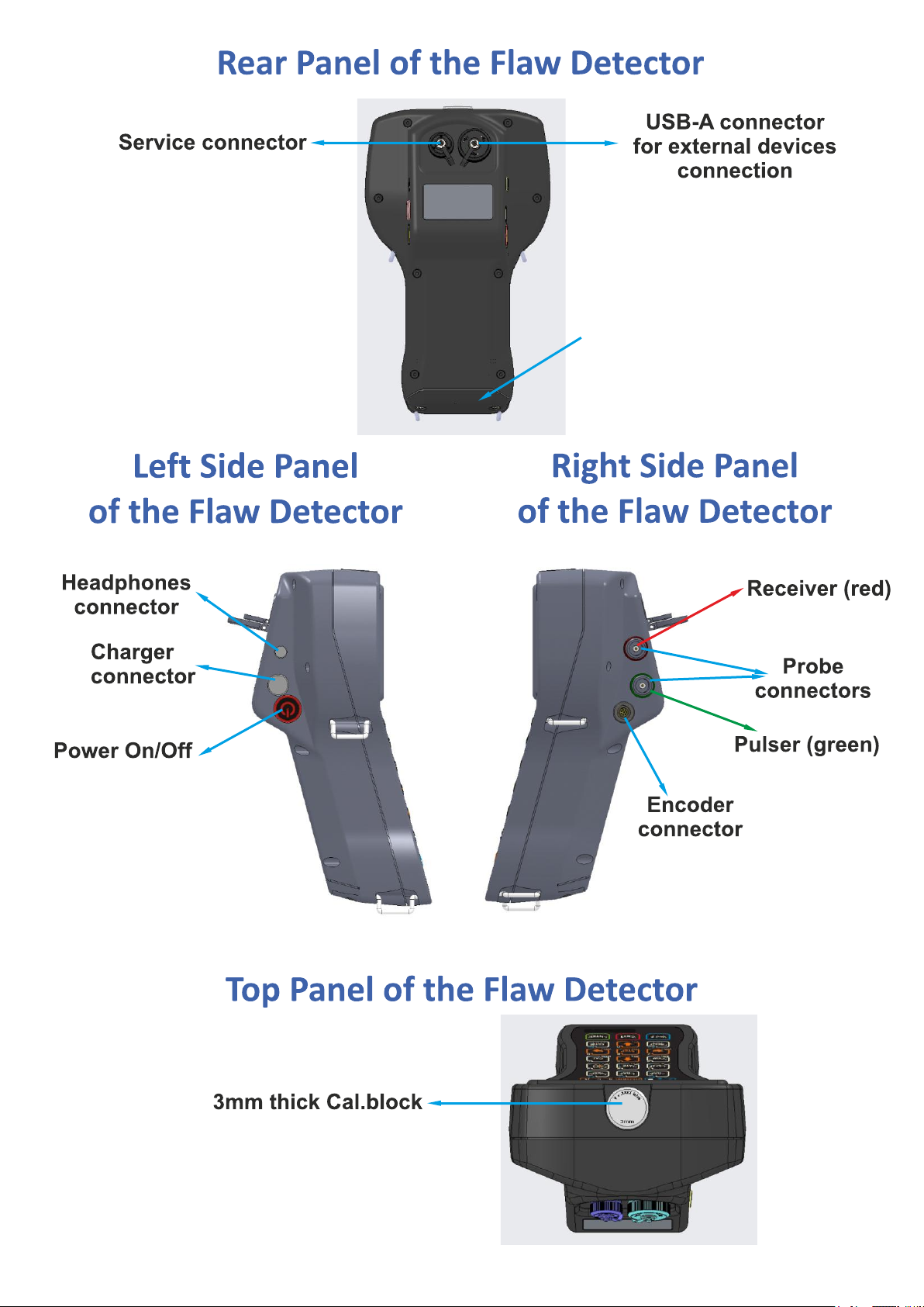
Battery compartment door
Page 3
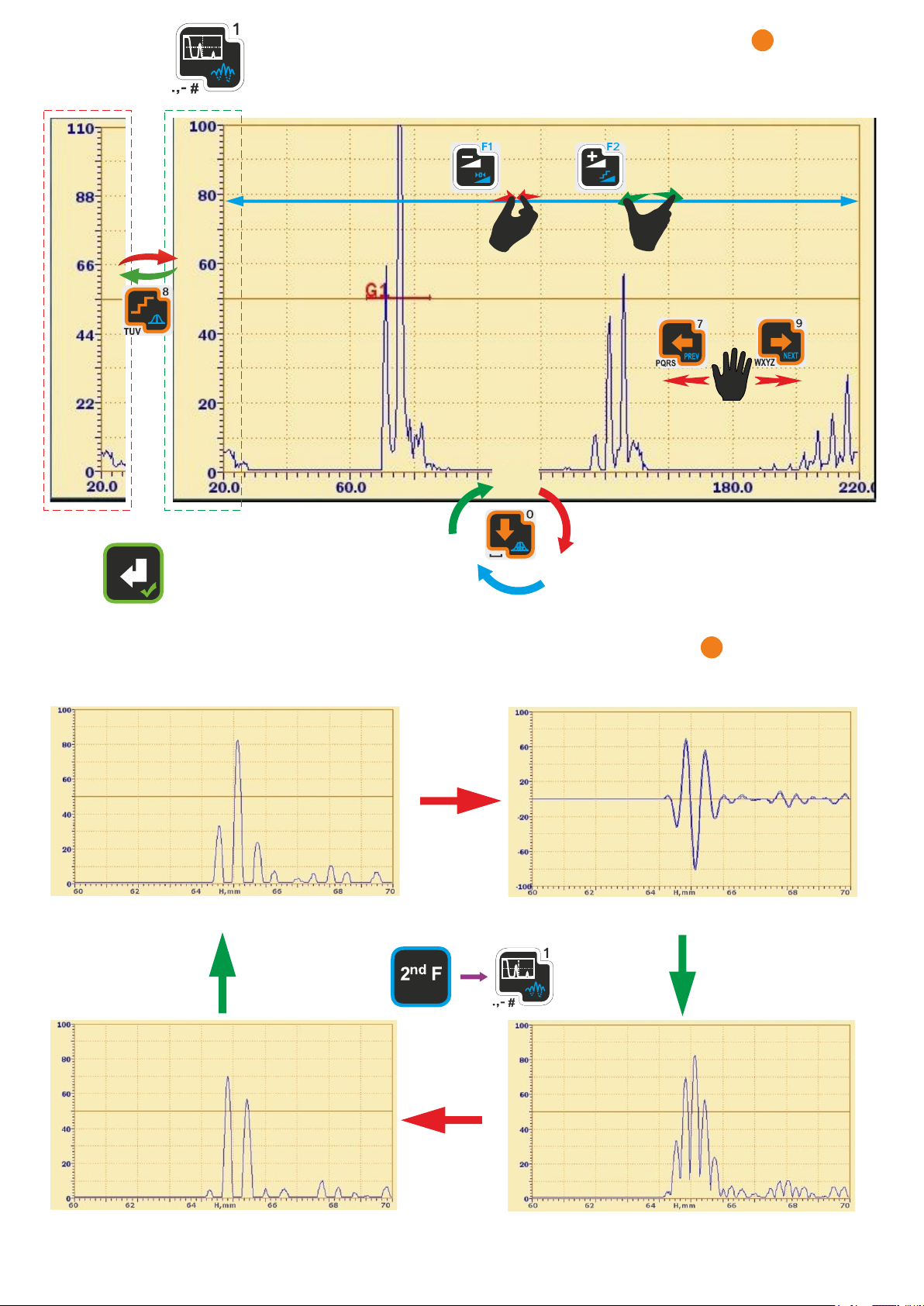
А-SCAN MANIPULATION
H,mm
С
- Full Screen
RECTIFICATION CHOICE
Negative halfwave
H,us
Y,mm
С
Radio Frequency
Positive halfwave
Full wave
-3-
Page 4
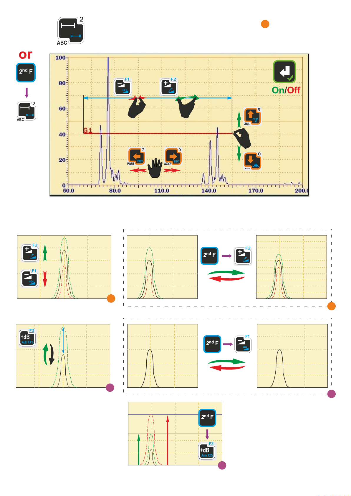
GATES MANIPULATION
H,mm
С
GAIN MANIPULATION
Gain adjustment
N, dB
Add / remove some
С
В
Gain step
variation
С
38dB 0dB
Reference
gain
В
number of dB
80%
50%
-4-
Put signal to the
reference level
(80% or 50%)
В
Page 5
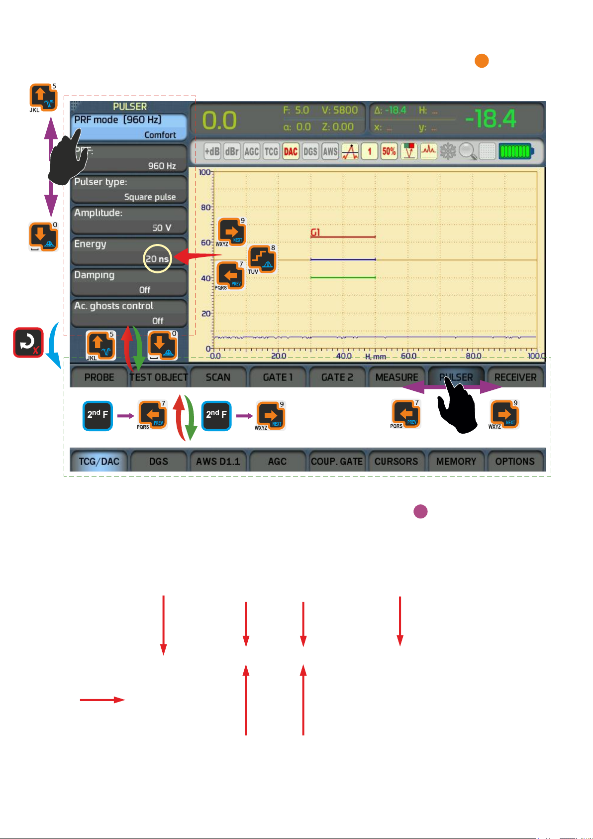
MENU NAVIGATION AND
PARAMETERS ADJUSTMENT
С
Indicators
panel
INDICATION PANEL
Gain
Probe
frequency
Probe
angle
Sound
velocity
Probe
zero
В
Measurands
-5-
Page 6
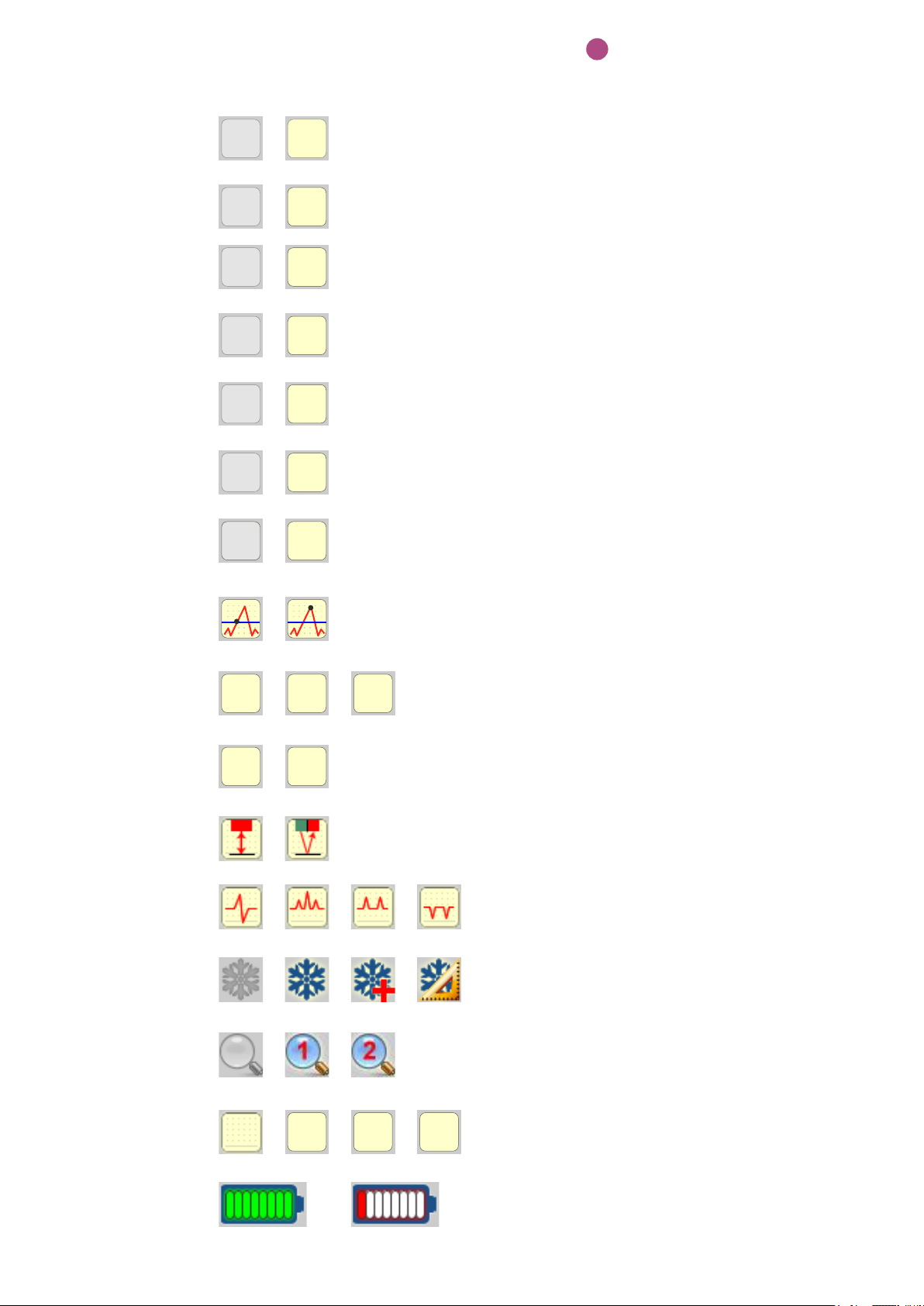
N dB addition
to the current
gain:
+dB +dB
/
В
INDICATORS
- Not added / Added
Reference
gain mode:
AGC:
TCG:
DAC system:
DGS system:
AWS rating:
Measurement
threshold:
/
dBrdBr
AGC AGC
DAC DAC
DGS DGS
AWS AWS
/
TCGTCG
/
/
/
/
/
- Off / On
- Inactive / Active
- Inactive / Active
- Inactive / Active
- Inactive / Active
- Inactive / Active
- Edge / Peak
Measurement
mode:
Reference level:
Probe type:
Rectification
mode:
Signal freeze
modes:
Zoom modes:
Direct
manipulation
modes:
1
50% 80%
1-2
/ /
/
/
/ / /
/ / /
/ /
ASC G1 G2
/ / /
2-C1
/
...
1, 2 – gates 1 and 2;
-
C1, C2 – cursors 1 and 2.
Reference level for amplitude
-
measurement
in % of vertical scale
- Single element / Dual element
Radio Frequency / Full wave /
-
Positive half waves /
Negative half waves
- Off / Frozen / Frozen + Live signals /
Estimate mode
- Off / Zooming gate 1 / Zooming gate 2
Off / A-Scan manipulation /
-
Gate 1 manipulation /
Gate 2 manipulation
Battery
indicator:
...
- Full / … / Almost empty
-6-
Page 7
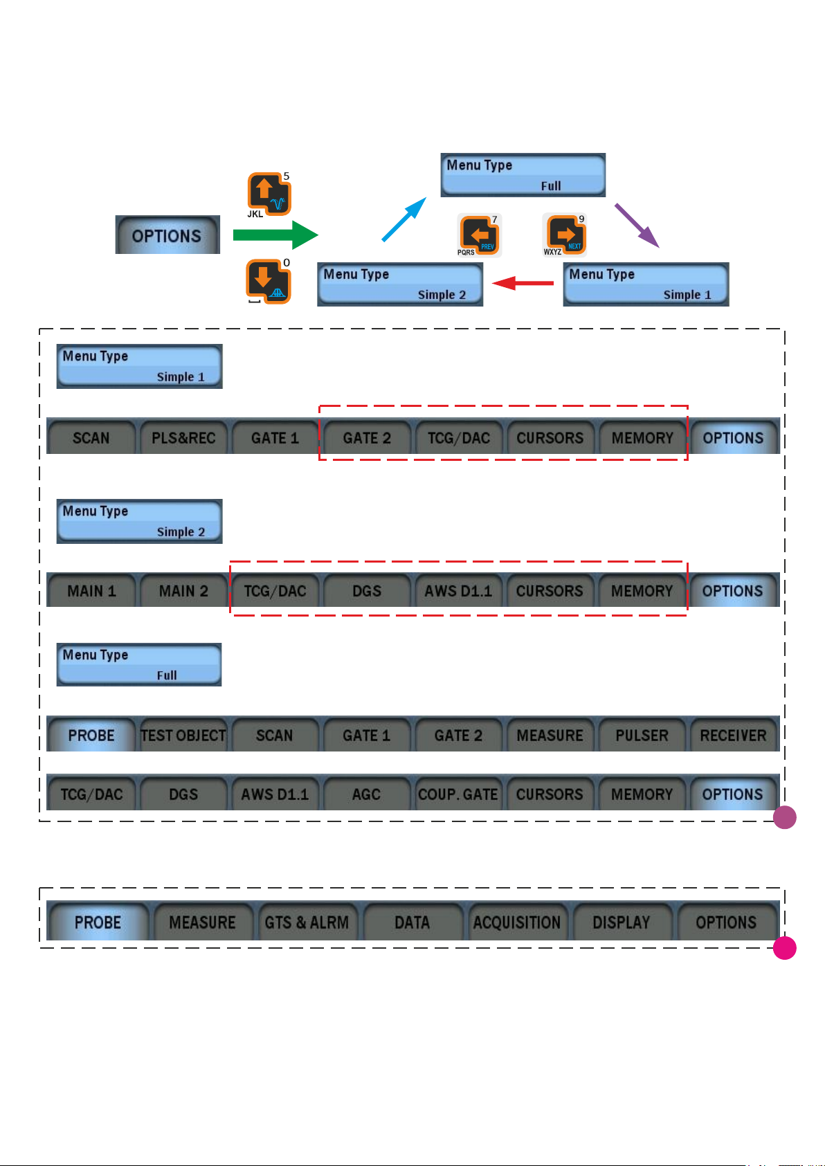
MENU STRUCTURE
In UT software version there are 3 sets of main menu - up to your choice:
user chosen menus
user chosen menus
In Thickness Gauge+ software version there is only one menu type:
В
-7-
Т
Page 8
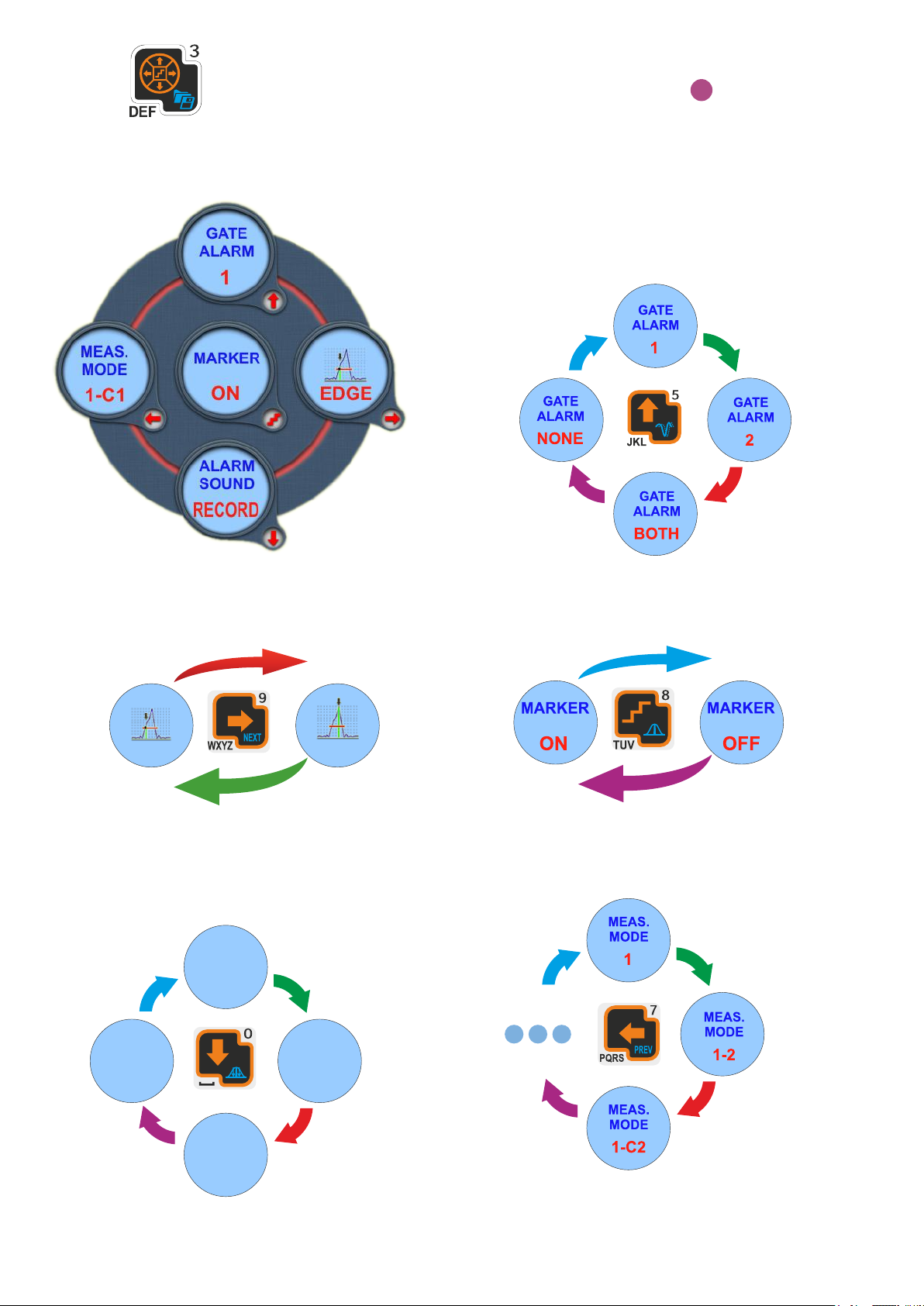
QUICK ACCESS
В
TO MAIN PARAMETERS
UT-B 1. Measurement and alarm
«Gates choice for Flaw Alarm System»
«Time/distance measurement
threshold choice»
EDGE
PEAK
«Choice of the gate(s) level
for the sound alarm»
ALARM
SOUND
ACCEPT.
ALARM
SOUND
OFF
ALARM
SOUND
RECORD
«Measurement point marker»
«Choice of gate(s) and cursor(s)
for absolute or relative measurements»
Absolute by gate 1
Relative
between
gate 1 and
gate 2
ALARM
SOUND
SEARCH
Relative between gate 1 and cursor 2
-8-
Page 9
QUICK ACCESS
TO MAIN PARAMETERS
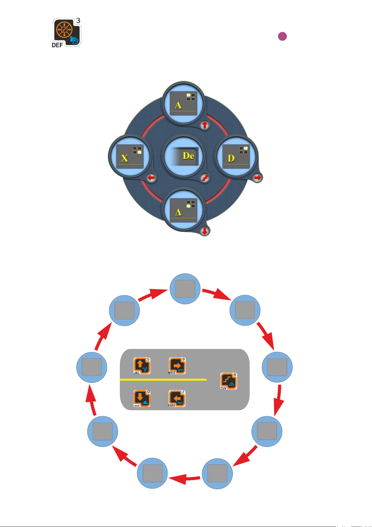
UT-B 2. Measurands choice
В
AWS rating
D
D
Equivalent area of
the indication
Se
Se
Maximum signal amplitude,
relative to the reference level
∆
∆
off
off
Par. 1
Par. 2
Par. 4
Par. 3
Main
parameter
A
A
Gain, necessary to get
maximum signal to
the reference level
Distance to
H
H
X
X
indication projection
to the scanning plane
the indication
along the beam
Distance to the
Equivalent diameter
of the indication
De
De
-9-
Y
Y
Indication depth
Page 10
QUICK ACCESS
TO MAIN PARAMETERS
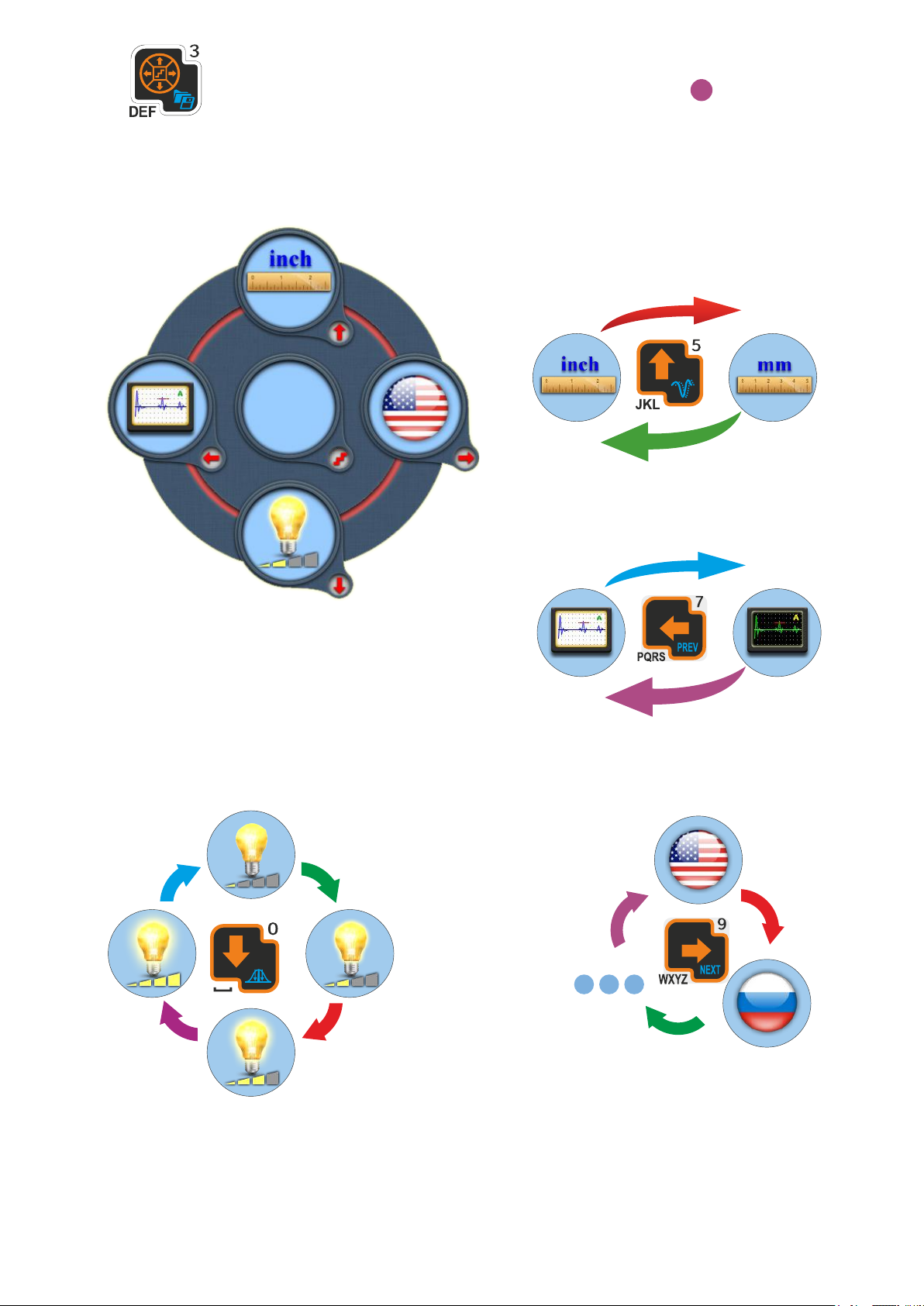
UT-B 3. Display options
«Switching measurement units»
В
«Display brightness adjustment»
«Switching color schemes»
Light
«Interface language choice»
Dark
-10-
Page 11
INDICATION SEARCH,
EVALUATION AND DOCUMENTATION AIDS
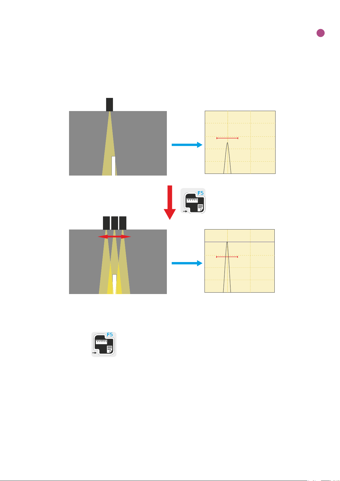
Evaluate mode
Helps finding the “best” signal. Just turn it on and scan.
P
55dB
G1
В
P
P P
80%
G1
42dB
Review all readings and save the indication if necessary
- switches evaluate mode off
and retrives the original gain
-11-
Page 12
INDICATION SEARCH,
EVALUATION AND DOCUMENTATION AIDS
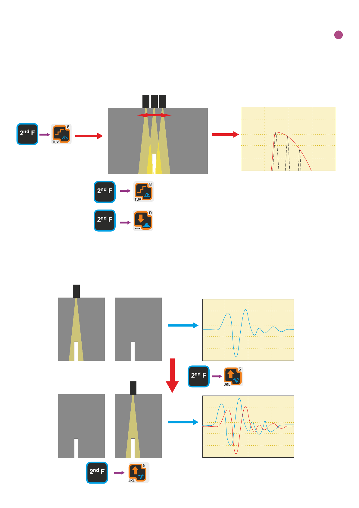
Peak hold mode
Saves the peak values of all signals along the A-Scan.
PP P
- Peak curve reset
В
- Peak hold mode off
Signals compare mode
Displays both “frozen” and current signals.
P
1
2
P
1
2
- Signals compare mode off
-12-
Page 13
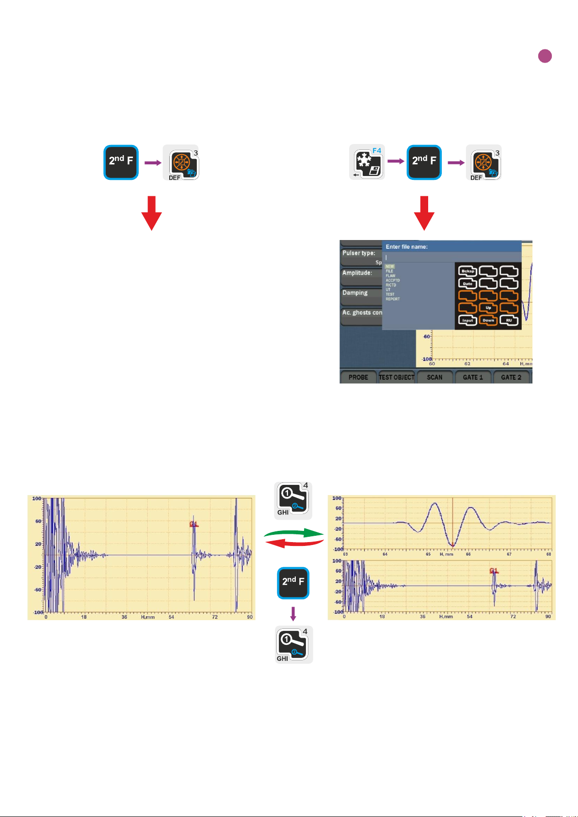
INDICATION SEARCH,
EVALUATION AND DOCUMENTATION AIDS
Memory shortcuts. Results saving
В
Smart zoom mode
or
-13-
Page 14
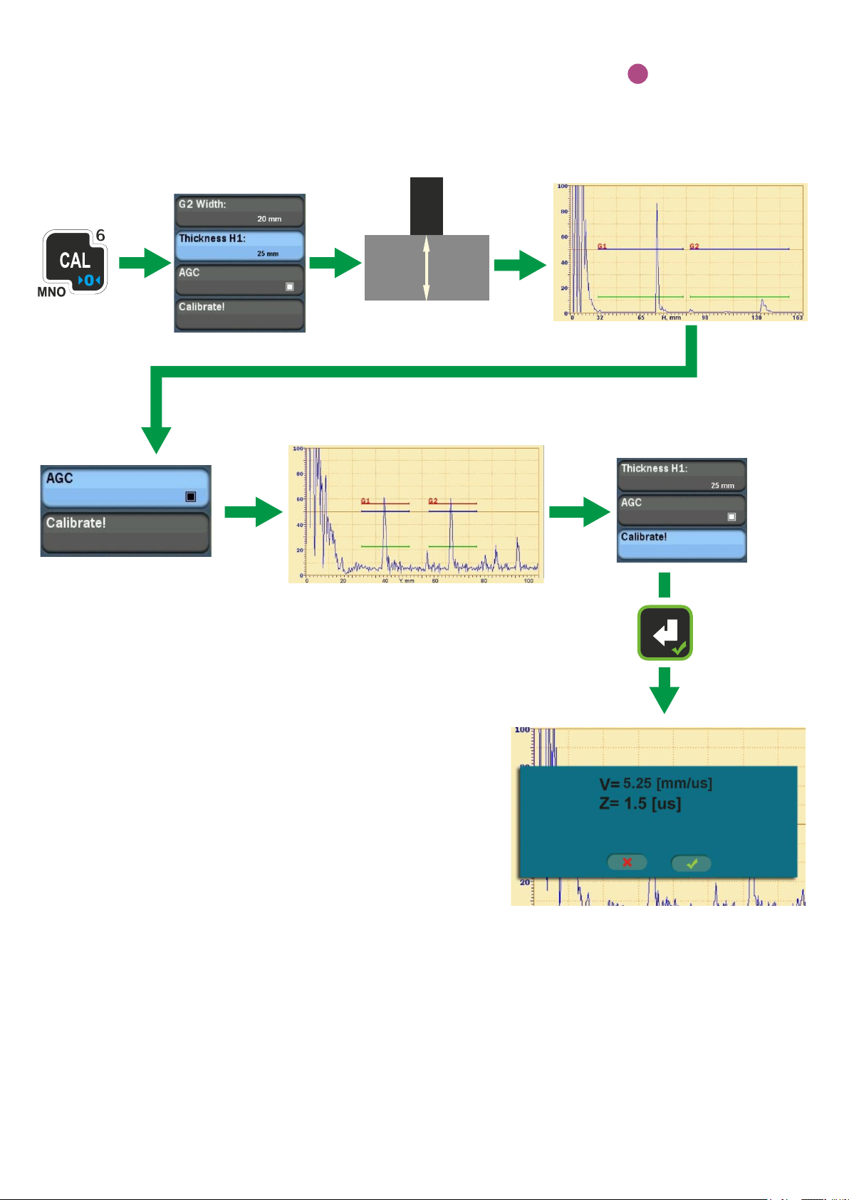
STRAIGHT-BEAM
PROBES CALIBRATION
Probe
В
-14-
Page 15
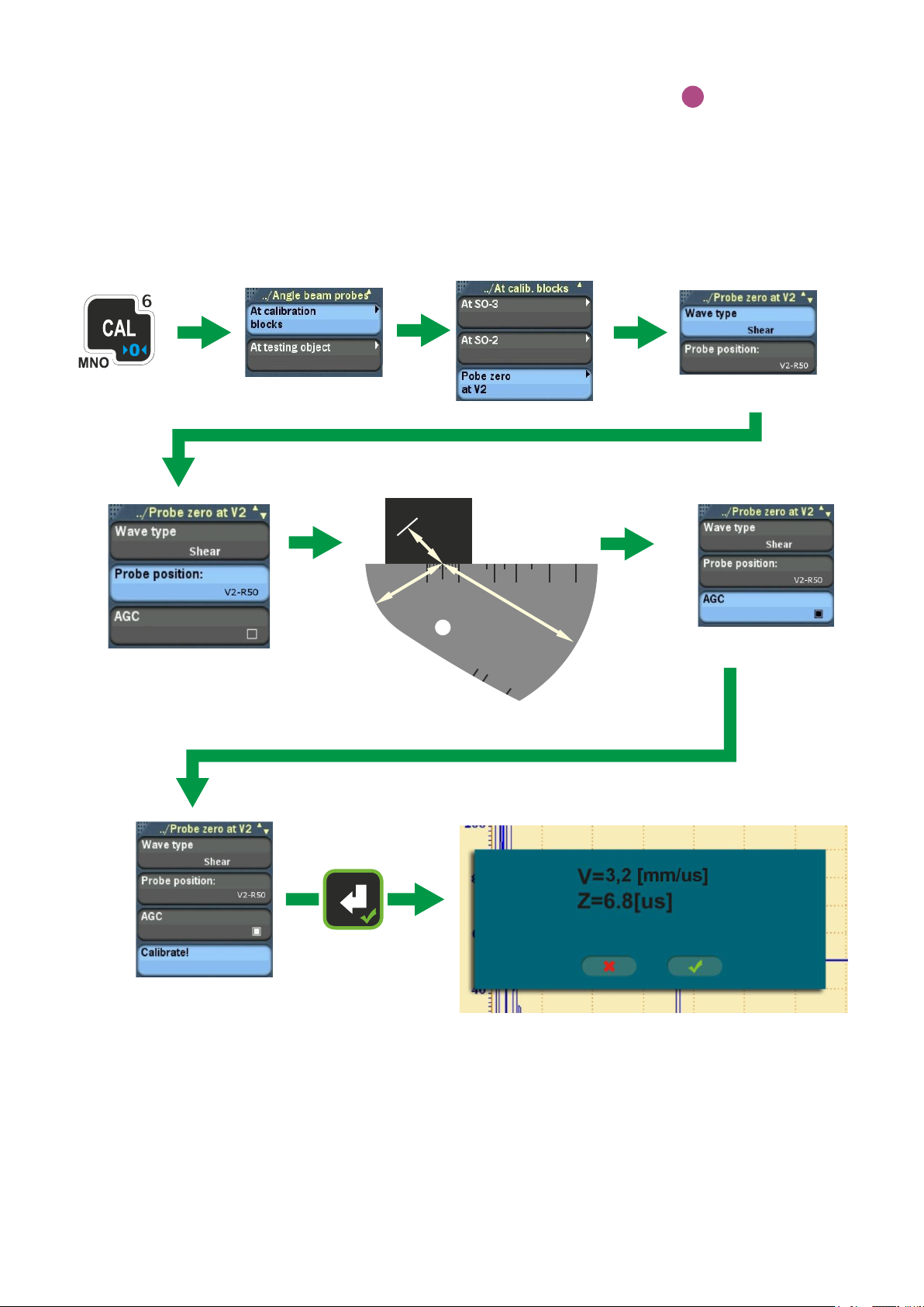
ANGLE-BEAM
В
PROBES CALIBRATION
Calibration of the sound velocity
and probe zero at V2 calibration block
Probe
0 40 50 60 65
65
70
75
-15-
Page 16
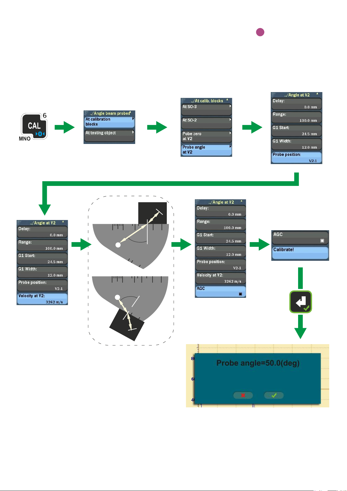
ANGLE-BEAM
В
PROBES CALIBRATION
Probe angle calibration at V2
Set up probe zero and sound velocity in V2 before strating this calibration.
V2-1
or
V2-2
Probe
0 40 60 65
0 40 60 65
Probe
50
α
65
70
75
50
α
65
70
75
-16-
Page 17
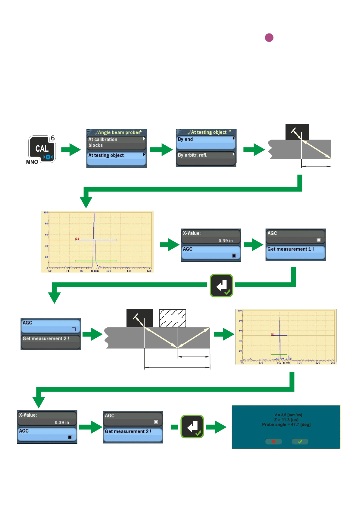
ANGLE-BEAM
В
PROBES CALIBRATION
Calibration of sound velocity and probe zero by
block or testing object end
Set up probe angle and X-value before starting this calibration
Probe
a
Probe
Probe
a
2 x a
-17-
Page 18
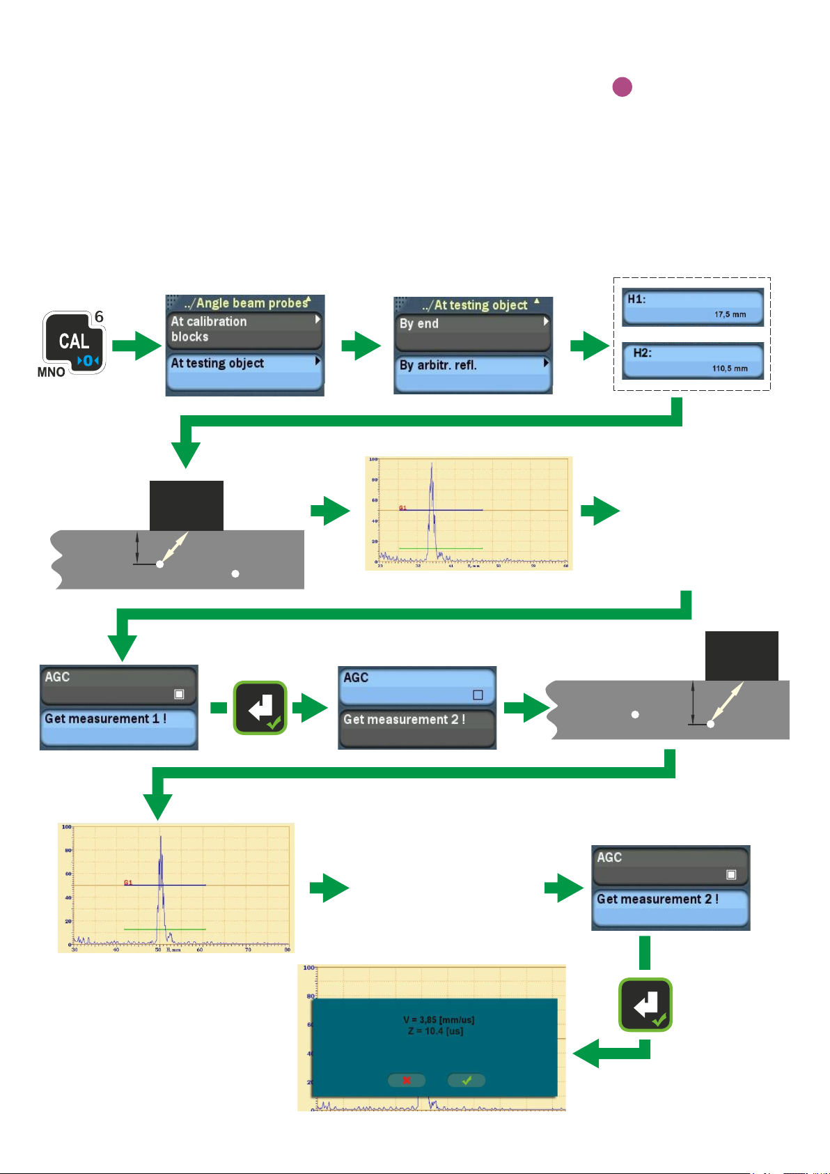
ANGLE-BEAM
В
PROBES CALIBRATION
Calibration of sound velocity and probe zero by
any reflectors with known location depth
Set up probe angle before starting this calibration
Н1
Probe
1
2
Probe
Н2
1
2
-18-
Page 19
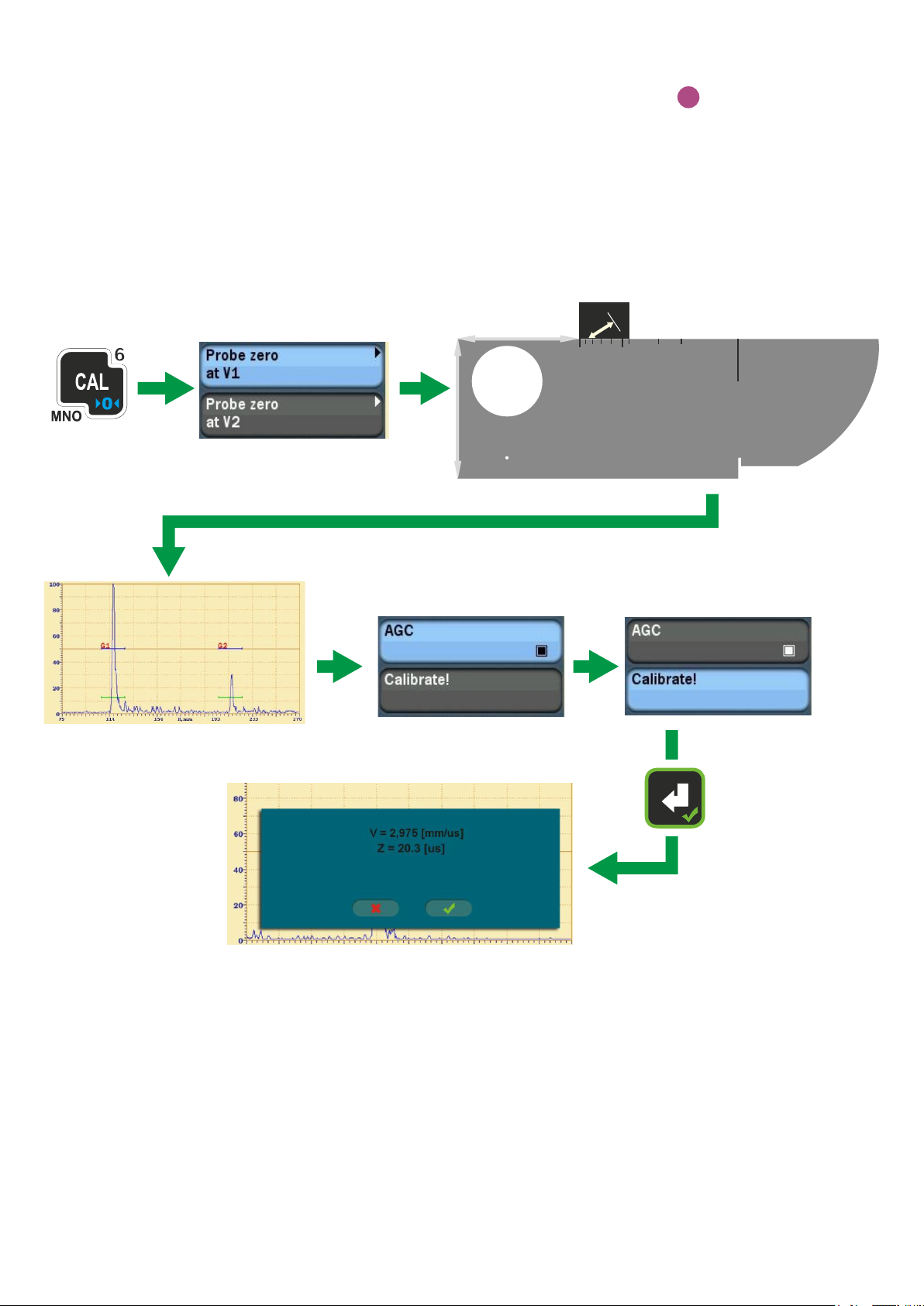
RAYLEIGH WAVE
В
PROBES CALIBRATION
Calibration of probe zero at V1 block
Set up probe angle = 90° before starting this calibration
Probe
70 76
60
-19-
Page 20
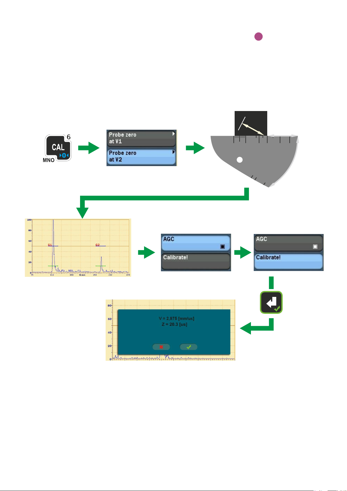
RAYLEIGH WAVE
В
PROBES CALIBRATION
Calibration of probe zero at V2 block
Set up probe angle = 90° before starting this calibration
Probe
0 40 50 60 65
65
70
75
-20-
Page 21
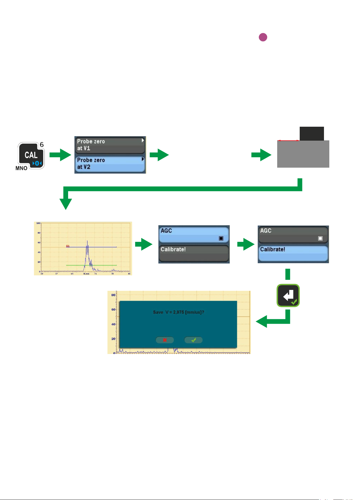
RAYLEIGH WAVE
В
PROBES CALIBRATION
Calibration of sound velocity at testing object
Set up probe angle = 90° before starting this calibration
«Х01»
Probe
-21-
Page 22

BASIC PREPARATION
Т
FOR THICKNESS MEASUREMENT
1. Connect probe and select it in the probes list – PROBE → Probe type (add it to
the list if necessary);
Calibrate probe zero (for details refer to next pages)2. ;
Set or calibrate sound velocity (for details refer to next pages3. );
Choose measurement type – MEASURE → Meas. type (0-1 by defaul4. t);
Choose AGC mode MEASURE → AGC mode (Peak by defaul5. t);
Specify such Maximum Gain Mode (MEASURE → MaxGain mode) and value of 6.
Maximum Gain (MEASURE → MaxGain) for manual mode, that Maximum Gain is
high enough to raise back wall echoes at all thicknesses to be measured at
necessary level and low enough that no noises come in the gate when probe
is in the air;
Adjust scan and gate (for details please refer to the beginning of this guide) so 7.
that back wall echoes at all thicknesses to be measured are in the gate limits;
Choose PRF mode (MEASURE → PRF mode)– High by default or other in case 8.
if acoustic ghost signals are detected.
ADDITIONAL PREPARATION
Т
FOR THICKNESS MEASUREMENT
1. Choose measurement threshold (MEASURE →Threshold: Edge / 0-Edge);
Choose measurement mode (MEASURE → Mode: Conventional / Min & Max / 2.
Differential / % of wear) and specify rated thickness for “Differential” and
“% of wear” modes;
Specify measurement frequency;3.
Switch on measurement point marker (GTS & ALRM → Marker)(visible in 4.
zoom mode);
Set alarm bounds (GTS & ALRM →Tmin and Tmax), alarm mode (GTS & ALRM →5.
Alarms), visualization (GTS & ALRM →Show alarm zones) and sound
(GTS & ALRM →Sound).
-22-
Page 23
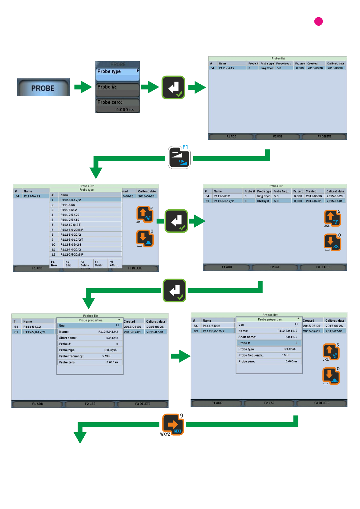
ADDING NEW PROBE TO THE LIST
Т
Continued at the next page
-23-
Page 24
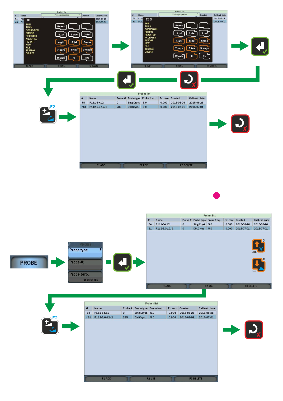
CHOOSING CONNECTED
PROBE FROM THE LIST
Т
Т
-24-
Page 25
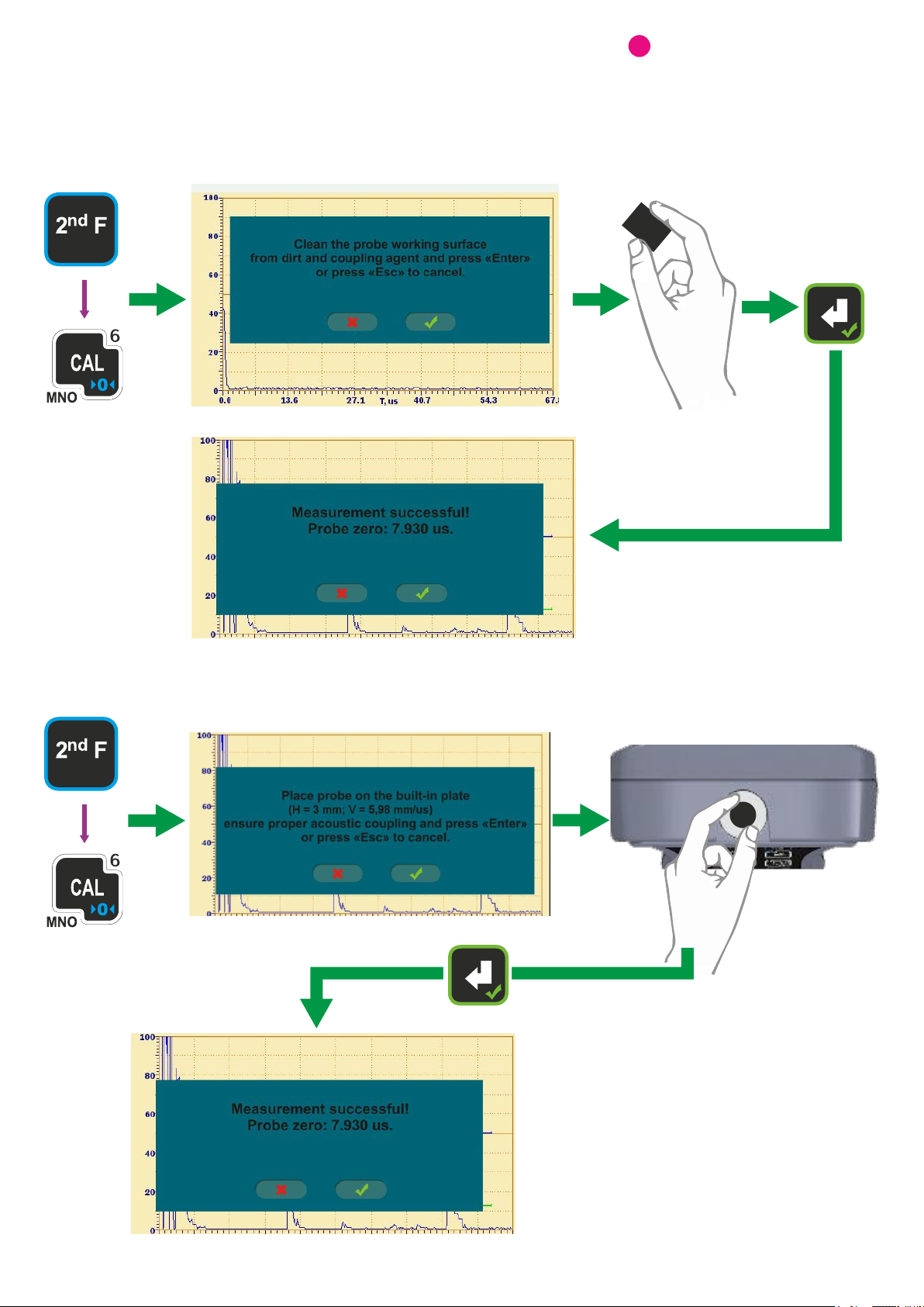
Т
PROBE ZEROING
Choose zero calibration mode (PROBE → Zero cal. mode: in air / on block)
Zeroing in “in air” mode
Probe
Zeroing in “on block” mode
Probe
-25-
Page 26
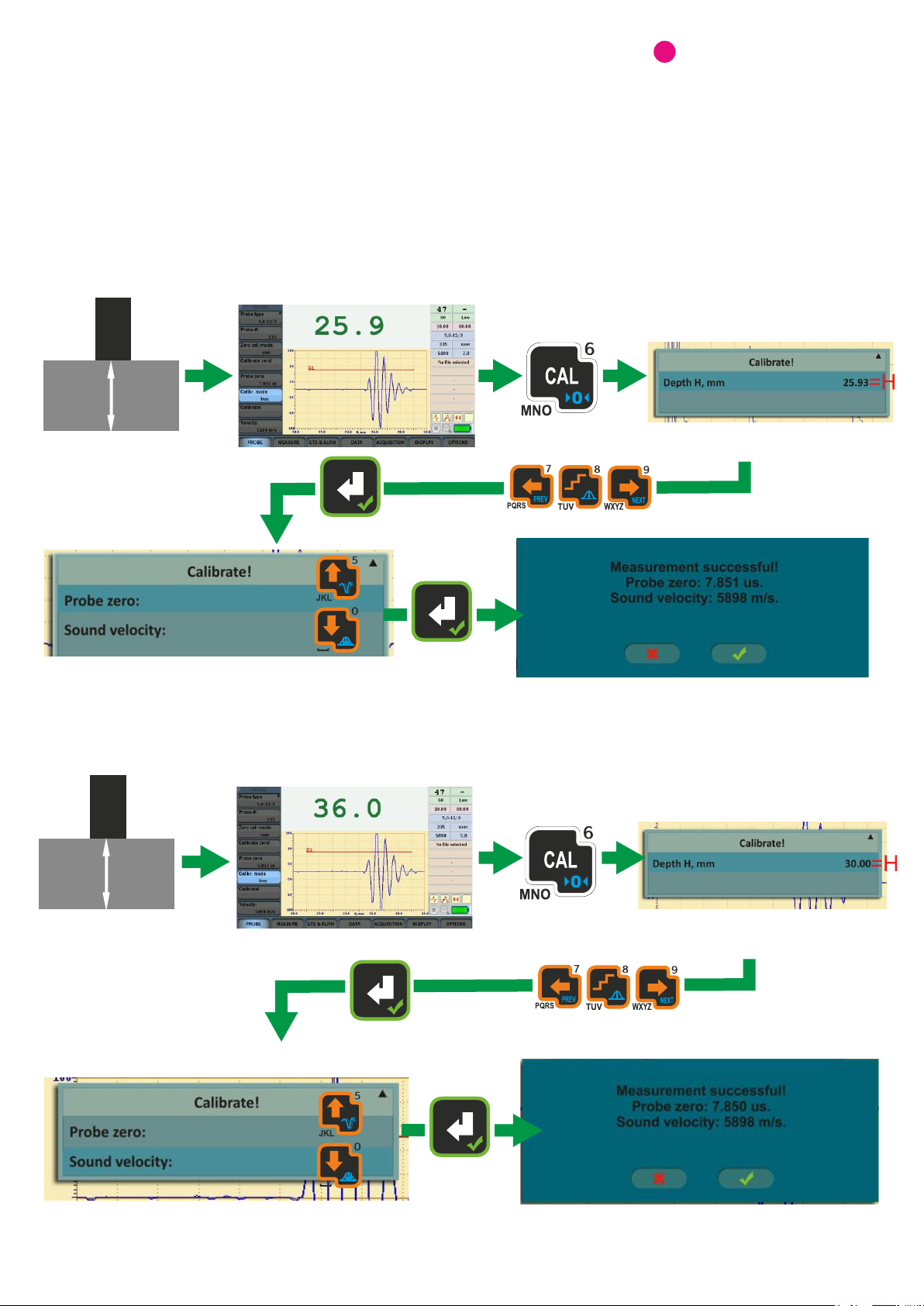
Т
FREE CALIBRATION
Should be chosen in PROBE → Calibr.mode
Prior to use free calibration all necessary preparations should be made and a
thickness reading (can be incorrect) at the calibration block (or other object with
known thickness) should be acquired.
Calibrating probe zero (sound velocity is already set)
Probe
Н
Calibrating sound velocity (the probe is already zeroed)
Probe
Н
-26-
Page 27
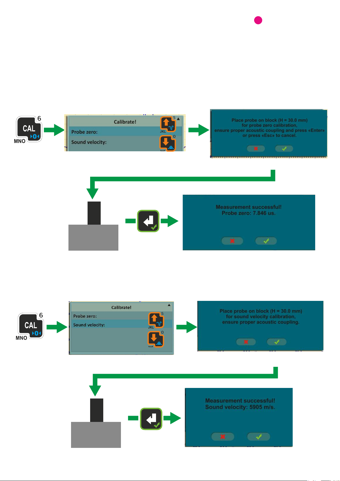
Т
1-POINT CALIBRATION
Should be chosen in PROBE → Calibr.mode
Prior to use 1-point calibration it is necessary to specify the calibration
block parameters in OPTIONS → Block 1pt menu.
Calibrating probe zero (sound velocity is already set)
Probe
Calibrating sound velocity (the probe is already zeroed)
Probe
-27-
Page 28
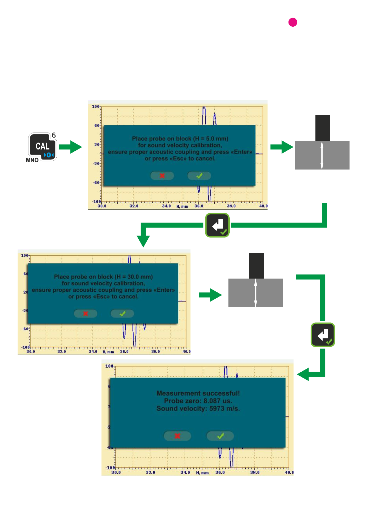
Т
2-POINTS CALIBRATION
Should be chosen in PROBE → Calibr.mode
Prior to use 2-point calibration it is necessary to specify the calibration
blocks parameters in OPTIONS → Block 2pts-1 and Block 2pts-2 menus.
Probe
Н1
Probe
Н2
Thicknesses of calibration blocks for 2-points calibration should differ
at least 2 times.
-28-
Page 29
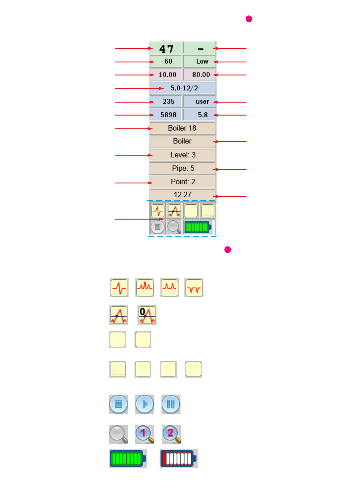
INDICATION PANEL
Т
Gain in gate 1
AGC maximum gain
Alarm lower thickness threshold
Probe short name
Probe number
Sound velocity
Current file name
Current place / point
index along the 1st file
dimension
Current place / point
index along the 3d file
dimension
Indicators panel
1
Gain in gate 2
Maximum gain mode
Alarm upper thickness
threshold
Probe zeroing mode
Probe zero value
Current file type
Current place / point
index along the 2nd file
dimension
Thickness value
recorded in the current
point or “free” or N/A
Rectification mode:
Measurement
threshold:
Measurement mode:
Direct manipulation:
modes
Indication of data
collection condition
at obtaining of slices /
thickness maps:
INDICATORS
/ / /
/
1
1-2
/
ASC G1 G2
/ / /
/ /
Т
Radio Frequency / Full wave /
Positive half waves /
-
Negative half waves
-
Edge / 0-Edge (by zero crossing)
Absolute (P-E) /
-
Relative (E-E) measurements
Off / A-Scan manipulation /
-
Gate 1 manipulation /
Gate 2 manipulation
Stopped / Active /
-
Paused
Zoom modes:
Battery indicator:
/ /
...
-29-
Off / Zooming gate 1 /
-
Zooming gate 2
-
Full / … / Almost empty
Page 30
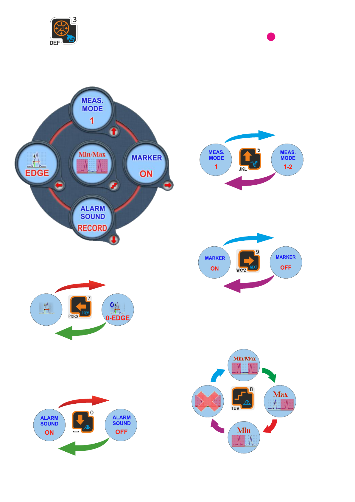
QUICK ACCESS
Т
TO MAIN PARAMETERS
TG+ 1. Gates choice for absolute or relative
measurements
«Choice of the measurement
mode: absolute or relative»
Absolute Relative
«Time/distance measurement
threshold choice»
EDGE
Edge
Edge zero
crossing
«Choice of the gate(s) level
for the sound alarm»
«Measurement point marker»
«Flaw alarm logic choice»
Both "Too thin" and " Too thick”
-30-
Оff
"Too Thick" only
"Too Thin" only
Page 31
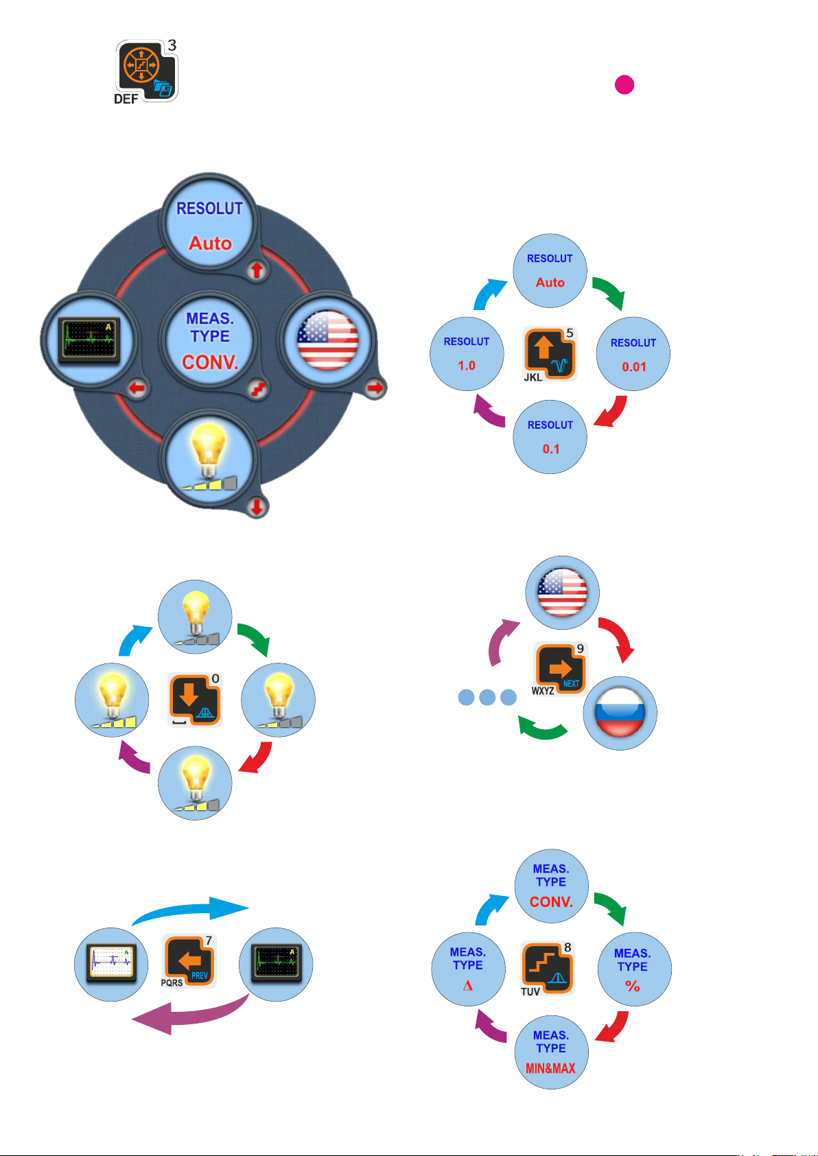
QUICK ACCESS
TO MAIN PARAMETERS
TG+ 2. Display options
«Resolution choice»
Т
«Display brightness adjustment»
«Switching color schemes»
«Interface language choice»
«Measurement type choice»
Normal
Light
Dark
Differential
-31-
Percents of wear
Min. and Max. fixation
Page 32
CONTENTS
С
A-Scan manipulation
С
Rectification Choice
С
Gates manipulation
С В
Gain manipulation
С
Menu navigation and parameters adjustment
В
Indication panel
В
Indicators
Т
В
Menu structure
В
Quick access to main parameters:
UT-B 1. Measurement and alarm
UT-B 2. Measurands choice
UT-B 3. Display options
В
Indication search, evaluation and documentation AIDS:
Evaluate mode
Peak hold mode
Signals compare
3
3
4
4
5
5
6
7
8
9
10
11
12
12
Memory shortcuts. Results saving
Zoom mode
В
Straight-beam probes calibration
В
Angle-beam probes calibration:
Calibration of the sound velocity and probe zero at V2 calibration block
Probe angle calibration at V2
Calibration of sound velocity and probe zero by block or testing object end
Calibration of sound velocity and probe zero by any reflectors with
known location depth
В
Rayleigh wave probes calibration:
Calibration of probe zero at V1 block
Calibration of probe zero at V2 block
Calibration of sound velocity at testing object
Т
Basic preparation for thickness measurement
Т
Additional preparation for thickness measurement
Т
Adding new probe to the list
13
13
14
15
16
17
18
19
20
21
22
22
23
Т
Choosing connected probe from the list
Т
Probe zeroing
Т
Free calibration
1-point calibration
Т
2-points calibration
Т
Т
Indication panel
Indicators
Т
Quick access to main parameters:
Т
TG+ 1. Gates choice for absolute or relative measurements
TG+ 2. Display options
24
25
26
27
28
29
29
30
31
 Loading...