


1
H401-T-PENNY
Temperature Controller
Manual
IST307_REV02
SV 1.2.6.0

2
Index
1 PREFACE ..................................................................................................................................................................................... 3
2 SYMBOL DESCRIPTION .......................................................................................................................................................... 4
2.1 SYMBOLS USED IN THIS MANUAL ...............................................................................................................................................................4
2.2 SYMBOLS ON THE PRODUCT LABEL ...........................................................................................................................................................4
3 SAFETY NOTES .......................................................................................................................................................................... 5
4 SUPPLIED EQUIPMENT .......................................................................................................................................................... 6
5 EQUIPMENT DESCRIPTION .................................................................................................................................................. 7
5.1 NAVIGATION BUTTONS ................................................................................................................................................................................7
5.1.1 ON/OFF device ................................................................................................................................................................................8
6 INSTALLATION ......................................................................................................................................................................... 9
6.1 COMPATIBILITY ............................................................................................................................................................................................9
6.2 CONNECTIONS OF THE HEATING DEVICE ............................................................................................................................................... 10
7 USER INTERFACE .................................................................................................................................................................. 11
7.1 HOMEPAGE ................................................................................................................................................................................................. 11
7.1.1 Status icons .................................................................................................................................................................................... 12
7.1.2 Entering the Setpoint temperature ..................................................................................................................................... 12
7.2 MENU NAVIGATION................................................................................................................................................................................... 13
7.2.1 Device selection ........................................................................................................................................................................... 14
7.2.1.1 Setting the proper Device Type .................................................................................................................................................................. 14
7.2.1.2 Advanced: How to manually set the control parameters ............................................................................................................... 16
7.2.2 Calibration ...................................................................................................................................................................................... 17
7.2.3 Alarm ................................................................................................................................................................................................ 21
7.2.4 Unit .................................................................................................................................................................................................... 22
7.2.5 Status page ..................................................................................................................................................................................... 22
7.2.6 System info ..................................................................................................................................................................................... 23
8 CLEANING & MAINTENANCE ............................................................................................................................................. 24
9 SUPPORT ................................................................................................................................................................................. 25
10 TECHNICAL SPECIFICATIONS ....................................................................................................................................... 26
11 TROUBLESHOOTING ........................................................................................................................................................ 27
12 FIGURE LIST ........................................................................................................................................................................ 28
13 TABLE LIST ......................................................................................................................................................................... 28
14 MANUAL REVISION TABLE ............................................................................................................................................ 28
15 QUICK GUIDE ...................................................................................................................................................................... 29

3
1 Preface
H401-T-PENNY is a compact single-channel temperature controller allowing to set and control the
temperature of a single channel Okolab heating device. It is a reliable solution to maintain the effective desired
temperature of the specimen right on the microscope stage within the range 25-60°C.
H401-T-PENNY includes the Temperature Controller, only. The heating device must be ordered
separately.
A variety of heating devices can be connected to H401-T-PENNY, for example: heating plates, both glass
and metal, for inverted, upright and stereo microscopes; glass heating tables; metal heating pads and objective
heaters. The heating plates –both glass and metal- are designed to fit into the opening of XY stages of upright and
inverted microscopes. Several models of glass and metal heating plates can be selected from the Okolab portfolio.
Custom solutions are available upon request. The glass heating table can be placed in the optical path of any
stereomicroscope and provides a large, flat, clear, warm surface where one or more specimens can be
maintained at physiological temperature. The glass heating table is also suitable for small animal surgery. The
metal heating pads are temperature-controlled surfaces that can be positioned on any laboratory workbench or
desk surface (e.g. table top, cabinet work surface, etc.) to keep Petri dishes, slides, and tubes at the right
temperature before microscope observation. The objective heater is a flexible heated band designed to maintain
the desired temperature of the objective body and lenses. It is necessary when the objective is in contact with the
sample during water dipping or oil immersion observation.
The H401-T-PENNY allows you to perform the heating device calibration by comparing its temperature
value with the value read by an external temperature meter (NOT SUPPLIED).
The H401-T-PENNY features an intuitive interface that combines performance and simplicity.
Okolab recommends reading carefully this manual to familiarize yourself with the functions and the
operation of H401-T-PENNY before use.
4
2 Symbol description
This paragraph describes the symbols used in this manual and on the product label.
2.1 Symbols used in this manual
The following symbols identify important information to note:
CAUTION or WARNING: this symbol warns you about the risk of electrical shock.
CAUTION or WARNING or IMPORTANT: this symbol warns you of circumstances or practices that
can affect the functionality of the instrument.
Tip ► Supplies you with helpful suggestions.
Note ► Supplies you with important information to successfully use the instrument.
2.2 Symbols on the product label
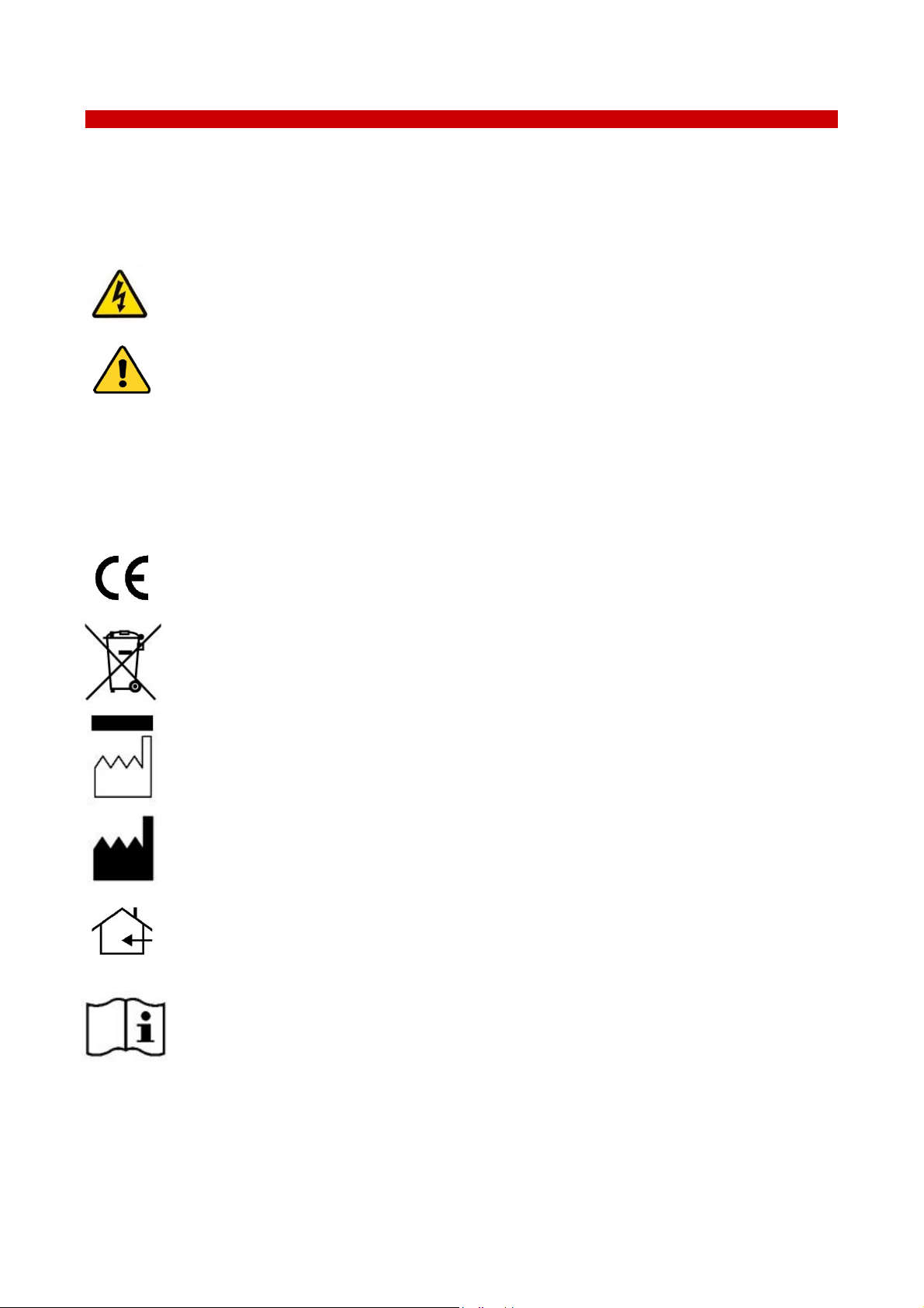
CE MARKING: this symbol indicates product compliance with EU legislation.
PRODUCT DISPOSAL: this symbol indicates that this product must not be disposed as urban
solid waste.
This symbol indicates the product production date.
This symbol indicates the Manufacturer data.
This symbol indicates the protection degree against ingress of solids or liquids inside the
product.
This symbol warns you to read the user manual before starting the device.
IP 30

5
3 Safety Notes
In order to achieve best performance and to ensure proper operation of your new equipment, please
read carefully the following safety notes and instructions. If you have any question, please contact Okolab at:
info@oko-lab.com
− The equipment must only be used as intended and as described in this Manual.
− Equipment should be operated only by technically qualified personnel.
− Do not start up the equipment if some of its parts are damaged.
− This instrument is not intended for use in locations subject to flammable or explosive gases.
− Transport the equipment with care.
− Equipment and its internal parts can be damaged by dropping and by shock.
− Some equipment parts may reach temperatures above 60°C. Take care when touching it.
− Avoid rapid changes in ambient temperature which may cause condensation, avoid direct air
draft from air conditioner, exposure to direct sunlight and excessive heat accumulation.
− Do not disassemble any part of the system.
− Do not disconnect cables while in operation.
− Do not use a volatile solvent such as paint thinner to clean the instrument, because deformation
or discoloration may occur.
− Use a soft, dry cloth to remove stains from the instrument.
− Do not exceed voltage indicated in this manual and on the product label.
− Avoid excessive induction noise, static electricity and magnetic fields.
− Do not expose this instrument to rain or moisture.
− Prevent throttling and kinking of cables.
− Do not start up the equipment if the supply cable is damaged.
− Connect the equipment only to grounded mains power socket.
− Before starting, assemble the equipment while unplugged from an outlet.
− Prevent metal fragments or lead wire scraps from falling inside instrument case to avoid
electric shock, fire or malfunction.
International caution symbol marks this device. IMPORTANT: read the “Safety Notes” before
installing, using and commissioning this device, as the notes contain important information relating
to safety and EMC. Not following these instructions can result in damage or breakdown of the
device and of its accessories.
We reserve the right to make technical modifications.
IN NO EVENT OKOLAB S.R.L. SHALL BE LIABLE FOR ANY DIRECT, INCIDENTAL OR CONSEQUENTIAL
DAMAGES OF ANY NATURE, OR FINANCIAL LOSS RESULTING FROM IMPROPER USE OF THE PRODUCT.
6
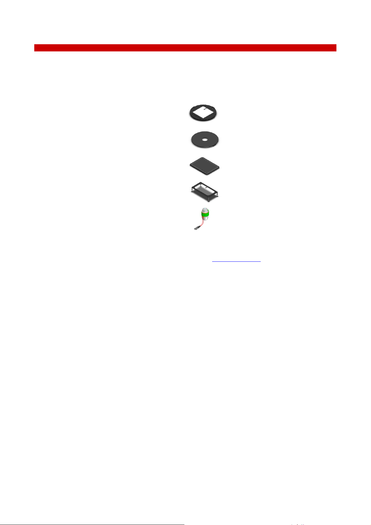
4 Supplied equipment
1 Controller. One channel temperature controller. See Figure 1 (1).
2 Device support/cradle. See Figure 1 (2)
3 Power supply and power cord. 24V DC-60 W power supply. See Figure 1 (3)
4 Heating device connector. See Figure 1 (4)
1
3
4
2
Figure 1. H401-T-PENNY – Components.
7
5 Equipment Description
H401-T-PENNY is a compact single-channel temperature controller allowing to set and control the
temperature of a single channel Okolab heating device. It is a reliable solution to maintain the effective desired
temperature of the specimen right on the microscope stage within the range 25-60°C.
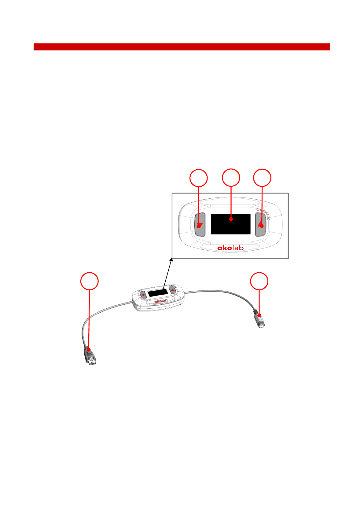
A detailed description of H401-T-PENNY is provided in the following list, which refers to the pointers in
Figure 2:
1 Heating Device connector
2 DOWN button (-)
3 Display
4 UP button (+)
5 24 VDC Power Input
1 5
2
3
4
Figure 2. H401-T-PENNY – Equipment description.
5.1 Navigation buttons
H401-T-PENNY has two navigation buttons:
• DOWN button (see Figure 2 (2))
• UP button (see Figure 2 (4))
There are two different press modes:
1 for 1 second
2 for 2 seconds
8
Keeping the buttons pressed for 1 or for 2 seconds allows you to access different features. The following
table lists the navigation buttons functions.
UP BUTTON for 1 second
Increase Value (+)
UP BUTTON for 2 seconds
Turn OFF/ON
DOWN BUTTON for 1
second
Decrease Value (-)
DOWN BUTTON for 2
seconds
Go to Menu
UP & DOWN BUTTONS at
the same time for 1 second
Enter
UP & DOWN BUTTONS at
the same time for 2 seconds
Cancel/Back
Table 1. UP and DOWN buttons functions.
5.1.1 ON/OFF device
To turn H401-T-PENNY on, keep the UP button pressed for 2 seconds (see Figure 3). The device will turn
ON.
Figure 3. Turning H401-T-PENNY on.
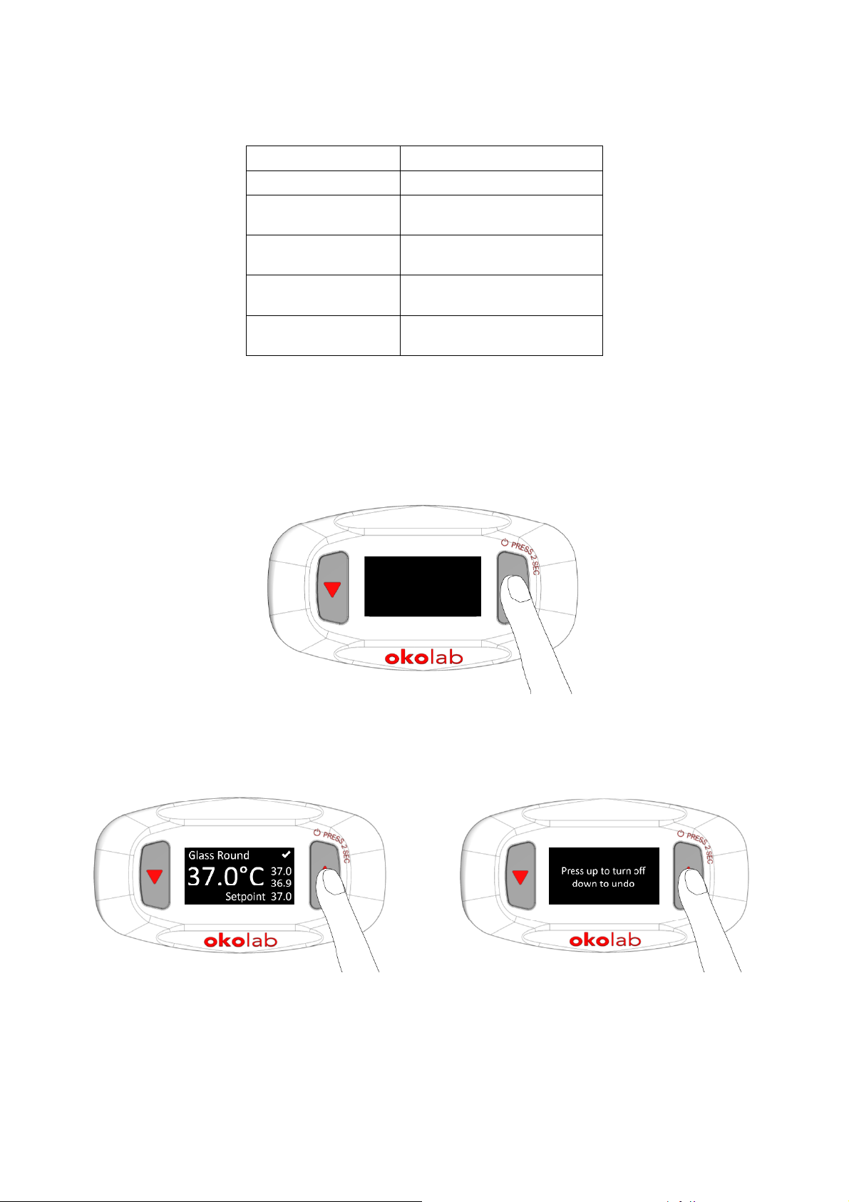
To turn H401-T-PENNY off, keep the UP button pressed for 2 seconds (see Figure 4 a), then press UP for
1 second, following the display info as shown in Figure 4 b. Press DOWN button for 1 second to undo.
a
b
Figure 4. Turning H401-T-PENNY off (a – b).
9
6 Installation
H401-T-PENNY can control the temperature of a single heating device.
6.1 Compatibility
H401-T-PENNY is compatible with the following Okolab heating devices:
− H601-T-GLASS series*
− H401-T-METAL series
− H401-T-PAD series
− H401-GLASS-TABLE
− OBJ-COLLAR-SERIES
*single channel
For a complete list of compatible heating devices, refer to: www.oko-lab.com.

10
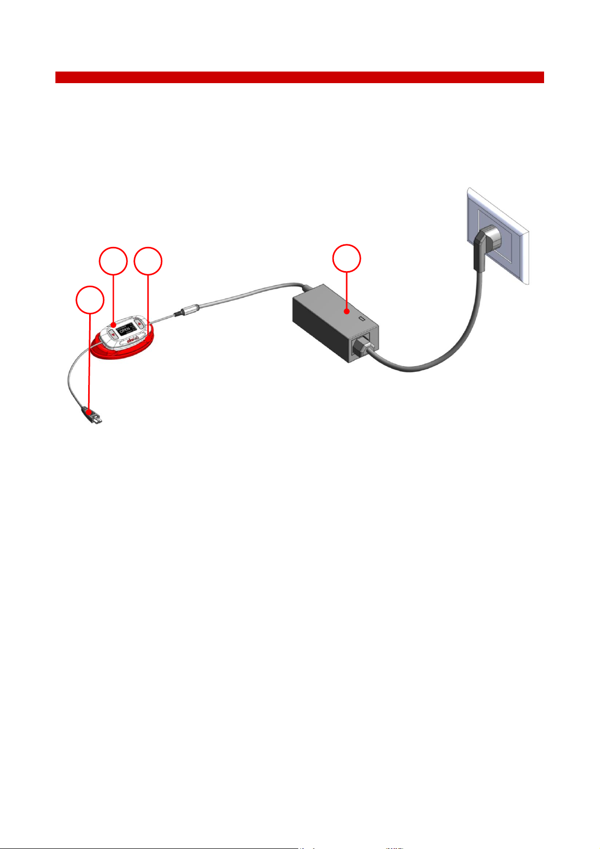
6.2 Connections of the heating device
Do not turn H401-T-PENNY ON until you have completed and checked all connections.
Follow the instructions below to connect the heating device to H401-T-PENNY.
24 VDC
Power
connector
Heating
Device
connector
Figure 5. Connection of the heating device.
1 Connect the heating device to the Heating Device connector of H401-T-PENNY (see Figure 5 and Figure 2
(1)).
2 Connect the Power Supply to the 24 VDC Power connector (see Figure 5 and Figure 2 (5)).
Use only the power supply provided by Okolab, to prevent system instability, random
reset, unexpected shutdown, or problems due to insufficient power.
For assistance, contact Okolab at support@oko-lab.com.
Do not connect AC power supply to your device until you have completed all the
connections shown in Figure 5.
11
7 User Interface
This chapter describes the user interface of H401-T-PENNY.
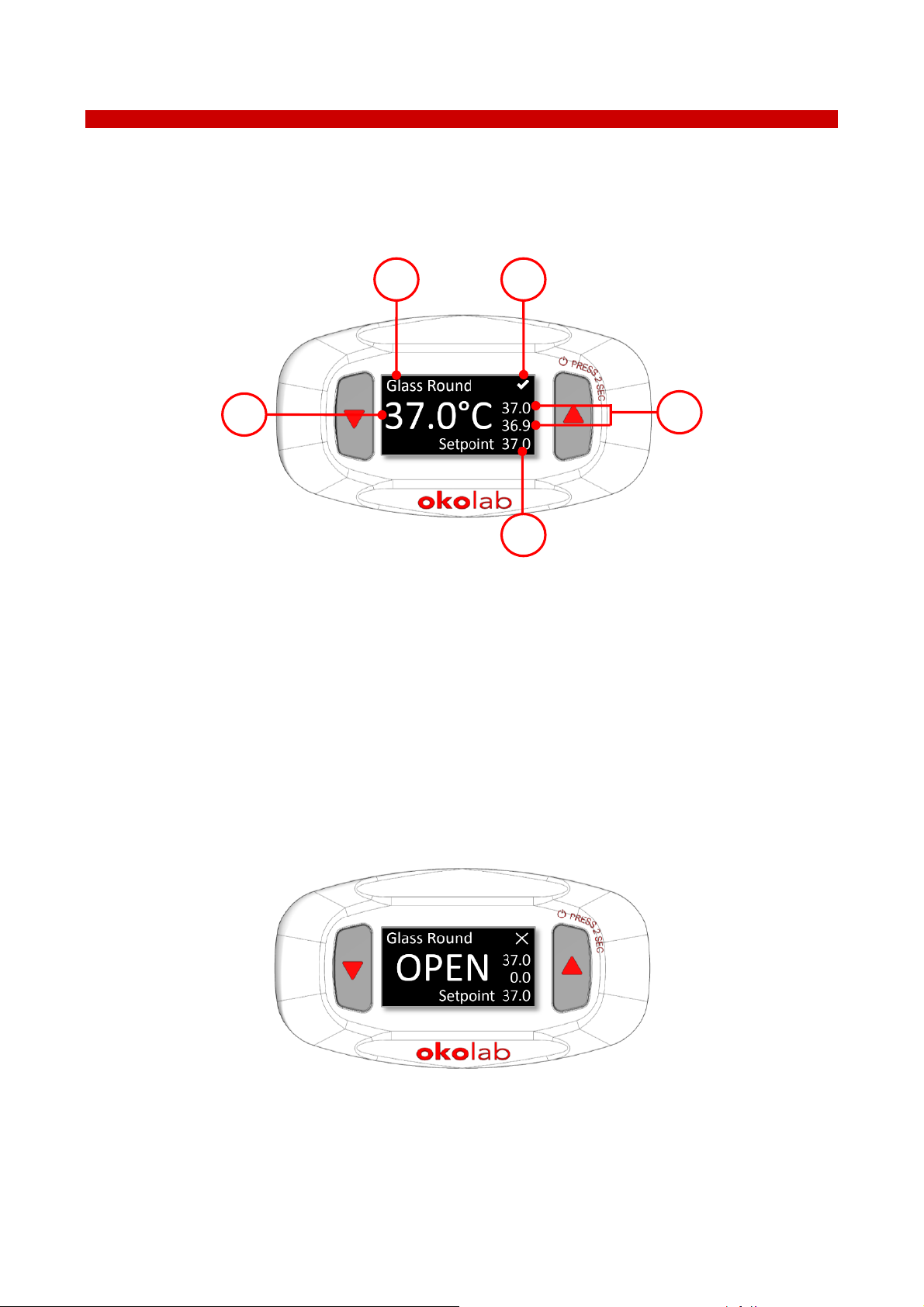
7.1 Homepage
Figure 6 shows the main display, in particular it highlights 5 points illustrated below.
1 2
4
3
5
Figure 6. Home page.
1 Device type category: it is the type of heating device connected to H401-T-PENNY. See paragraph 7.2.1.1
2 Status Icon: it represents the device status. See paragraph 7.1.1.
3 Device Minimum and Maximum temperatures reading within 1 minute.
4 Device temperature Setpoint. See paragraph 7.1.2.
5 Device temperature current value.
Tip ► Setpoint Temperature is pre-set at 37. Once turned on, H401-T-PENNY will start operating to reach
37.
Note ► If no device is connected, the display shows OPEN, see Figure 7.
Figure 7. Home page with no device connected.
 Loading...