


1
H401-T-CONTROLLER
Temperature Controller
Manual
IST747_REV01
SV 2.3.8.2

2
Index
Index
1 PREFACE ..................................................................................................................................................................................... 4
2 SYMBOL DESCRIPTION .......................................................................................................................................................... 5
2.1 SYMBOLS USED IN THIS MANUAL ...............................................................................................................................................................5
2.2 SYMBOLS ON THE PRODUCT LABEL ...........................................................................................................................................................5
3 SAFETY NOTES .......................................................................................................................................................................... 6
4 SUPPLIED EQUIPMENT .......................................................................................................................................................... 7
5 OPTIONAL EQUIPMENT ......................................................................................................................................................... 7
6 EQUIPMENT DESCRIPTION .................................................................................................................................................. 8
7 INSTALLATION ......................................................................................................................................................................... 8
7.1 COMPATIBILITY ............................................................................................................................................................................................9
7.2 CONNECTIONS OF THE HEATING DEVICES ............................................................................................................................................. 10
7.3 MINI-USB PORT ...................................................................................................................................................................................... 11
7.3.1 Connection of a USB drive ....................................................................................................................................................... 11
7.3.2 PC Connection via USB .............................................................................................................................................................. 11
7.4 RS232 PORT – PC CONNECTION VIA RS232 ...................................................................................................................................... 12
7.5 ALARM SCREW TERMINAL ....................................................................................................................................................................... 13
8 USER INTERFACE .................................................................................................................................................................. 14
8.1 HOMEPAGE ................................................................................................................................................................................................. 14
8.1.1 How to enter the set point temperature ........................................................................................................................... 15
8.1.2 Controller Status: colours and meaning............................................................................................................................ 16
8.2 SETTINGS .................................................................................................................................................................................................... 17
8.2.1 Device configuration .................................................................................................................................................................. 17
8.2.1.1 Device Type ......................................................................................................................................................................................................... 18
8.2.1.2 Device Label ....................................................................................................................................................................................................... 18
8.2.1.3 Device Maximum Heating Ramp Rate .................................................................................................................................................... 19
8.2.2 Calibration routines ................................................................................................................................................................... 20
8.2.2.1 Heating Device Calibration ......................................................................................................................................................................... 20
8.2.2.2 T Sensor Calibration ....................................................................................................................................................................................... 27
8.2.3 Data Logging .................................................................................................................................................................................. 29
8.2.4 Alarms .............................................................................................................................................................................................. 32
8.2.5 Display configuration ................................................................................................................................................................ 34
8.2.5.1 Display Options ................................................................................................................................................................................................. 34
8.2.5.2 Display Brightness ........................................................................................................................................................................................... 35
8.2.5.3 Display Calibration ......................................................................................................................................................................................... 35
8.2.5.4 Date & Time ........................................................................................................................................................................................................ 36
8.2.5.5 Display Visual Effects – icon and glance mode ................................................................................................................................... 36
8.2.6 Password ......................................................................................................................................................................................... 37
8.2.7 Summary ......................................................................................................................................................................................... 38
8.3 OVERVIEW STATUS PAGE ........................................................................................................................................................................ 39
8.4 ICON AND GLANCE MODE VIEW ............................................................................................................................................................. 39
8.5 INFO PAGE .................................................................................................................................................................................................. 40
9 CLEANING & MAINTENANCE ............................................................................................................................................. 40
10 H401-T-CONTROLLER-OEM .......................................................................................................................................... 41
10.1 DESCRIPTION ............................................................................................................................................................................................. 41
10.2 EQUIPMENT SUPPLIED ............................................................................................................................................................................. 41
10.3 INSTALLATION. .......................................................................................................................................................................................... 42
10.3.1 Connections of the heating devices ..................................................................................................................................... 44
10.3.2 T sensor Connection .................................................................................................................................................................. 45

3
10.3.3 MINI-USB port .............................................................................................................................................................................. 46
10.3.3.1 Connection of a USB drive ............................................................................................................................................................................ 47
10.3.3.2 PC Connection via USB................................................................................................................................................................................... 47
10.3.4 Alarm Screw Terminal .............................................................................................................................................................. 47
11 SUPPORT ............................................................................................................................................................................. 48
12 TECHNICAL SPECIFICATIONS ....................................................................................................................................... 50
13 TROUBLESHOOTING ........................................................................................................................................................ 51
14 FIGURE LIST ........................................................................................................................................................................ 52
15 TABLE LIST ......................................................................................................................................................................... 53
16 MANUAL REVISION TABLE ............................................................................................................................................ 53
17 LIST OF SPARE PARTS FOR H401-T-CONTROLLER AND H401-T-CONTROLLER-OEM ........................... 53

4
1 Preface
The H401-T-CONTROLLER is a touch screen digital dual channel temperature controller and data log
device allowing temperature set up, control and logging of two separate heating devices. It is a compact and
reliable solution to maintain the effective desired temperature of the specimen right on the microscope stage
within the range 25-60°C. The H401-T-CONTROLLER allows to set two different temperatures for the two
devices.
The H401-T-CONTROLLER comprises the Temperature Controller and a miniaturized water / oil
immersible temperature sensor. The temperature sensor allows to calibrate the heating devices with great
accuracy, by providing feedback from the temperature of the culture medium contained inside the dish. The
heating devices must be purchased separately.
A variety of heating devices can be connected to the H401-T-CONTROLLER, for example: heating plates both glass and metal for inverted, upright and stereo microscopes, glass heating tables, metal heating pads, stage
heating pads or objective heaters. The heating plates –both glass and metal- are designed to fit into the opening
of XY stages of upright and inverted microscopes. Several models of glass and metal heating plate inserts can be
selected from the Okolab portfolio. Custom solutions are available upon request. The glass heating table can be
placed in the optical path of any stereomicroscope and provides a large, flat, clear, warm surface where one or
more specimens can be maintained at physiological temperature. The glass heating table is also suitable for small
animal surgery. The metal heating pads are temperature-controlled surfaces that can be positioned on any
laboratory workbench or desk surface (e.g. table top, cabinet work surface, etc.) to keep Petri dishes, slides, and
tubes at the right temperature before microscope observation. The stage heating pads clamp on the XY stage and
create a temperature-controlled, flat surface on the entire stage, with the exception of the central part, which can
be covered with a glass or metal heating insert. The objective heater is a flexible heated band designed to
maintain the desired temperature of the objective body and lenses. This is important when the objective is in
contact with the sample during water dipping or oil immersion observation.
The H401-T-CONTROLLER features an intuitive, user-friendly touch screen interface that enables you to
perform accurate calibrations in an efficient and simple manner.
The H401-T-CONTROLLER is also equipped with on-board memory for data logging and storage. A
simple routine allows to download data to USB drive or to PC.
We recommend reading carefully this manual to familiarize yourself with the functions and the
operation of H401-T-CONTROLLER before use.

5
2 Symbol description
This paragraph describes the symbols used in the manual and on the product label.
2.1 Symbols used in this manual
The following symbols identify important information to note:
CAUTION or WARNING: this symbol warns you about the risk of electrical shock.
CAUTION or WARNING or IMPORTANT: this symbol warns you of circumstances or practices that
can affect the functionality of the instrument.
Tip ► Supplies you with helpful suggestions.
Note ► Supplies you with important information to successfully setup and use the instrument.
2.2 Symbols on the product label
CE MARKING: this symbol indicates product compliance with EU legislation.
PRODUCT DISPOSAL: this symbol indicates that this product must not be disposed as urban
solid waste.
This symbol indicates the product production date.
This symbol indicates the manufacturer data.
This symbol indicates the protection degree against ingress of solids or liquids inside the
product.
This symbol warns you to read the user manual before starting the device.
6
3 Safety Notes
In order to achieve maximum performance and to ensure proper operation of your new equipment,
please read carefully the following safety notes and the instructions. If you have any question, please contact
Okolab.
The equipment must only be used as intended and as described in this Manual.
Equipment should be operated only by technically qualified personnel.
Do not start up the equipment if some of its parts are damaged.
This instrument is not intended for use in locations subject to flammable or explosive gases.
Transport the equipment with care.
Equipment and its internal parts can be damaged by dropping and by shock.
Some equipment parts may reach temperatures above 60°C. Take care when touching it.
Avoid rapid changes in ambient temperature which may cause condensation, avoid direct air
draft from air conditioner, exposure to direct sunlight and excessive heat accumulation.
Do not disassemble any part of the system.
Do not disconnect cables while in operation.
Do not use a volatile solvent such as paint thinner to clean the instrument because deformation
or discoloration may occur.
Use a soft, dry cloth to remove stains from the instrument.
Do not exceed voltage indicated in this manual and on the product label.
Avoid excessive induction noise, static electricity and magnetic fields.
Do not expose this instrument to rain or moisture.
Prevent throttling and kinking of cables.
Do not start up the equipment if the supply cable is damaged.
Connect the equipment only to grounded mains power socket.
Before starting, assemble the equipment while unplugged from an outlet.
Prevent metal fragments or lead wire scraps from falling inside instrument case to avoid
electric shock, fire or malfunction.
International caution symbol marks this device. IMPORTANT: read the “Safety Notes” before
installing, using and commissioning this device, as the notes contain important information relating
to safety and EMC. Not following these instructions can result in damage or breakdown of the
device and its accessories.
We reserve the right to make technical modifications.
IN NO EVENT OKOLAB S.R.L. SHALL BE LIABLE FOR ANY DIRECT, INCIDENTAL OR CONSEQUENTIAL
DAMAGES OF ANY NATURE, OR FINANCIAL LOSS RESULTING FROM IMPROPER USE OF THE PRODUCT.
7
4 Supplied equipment
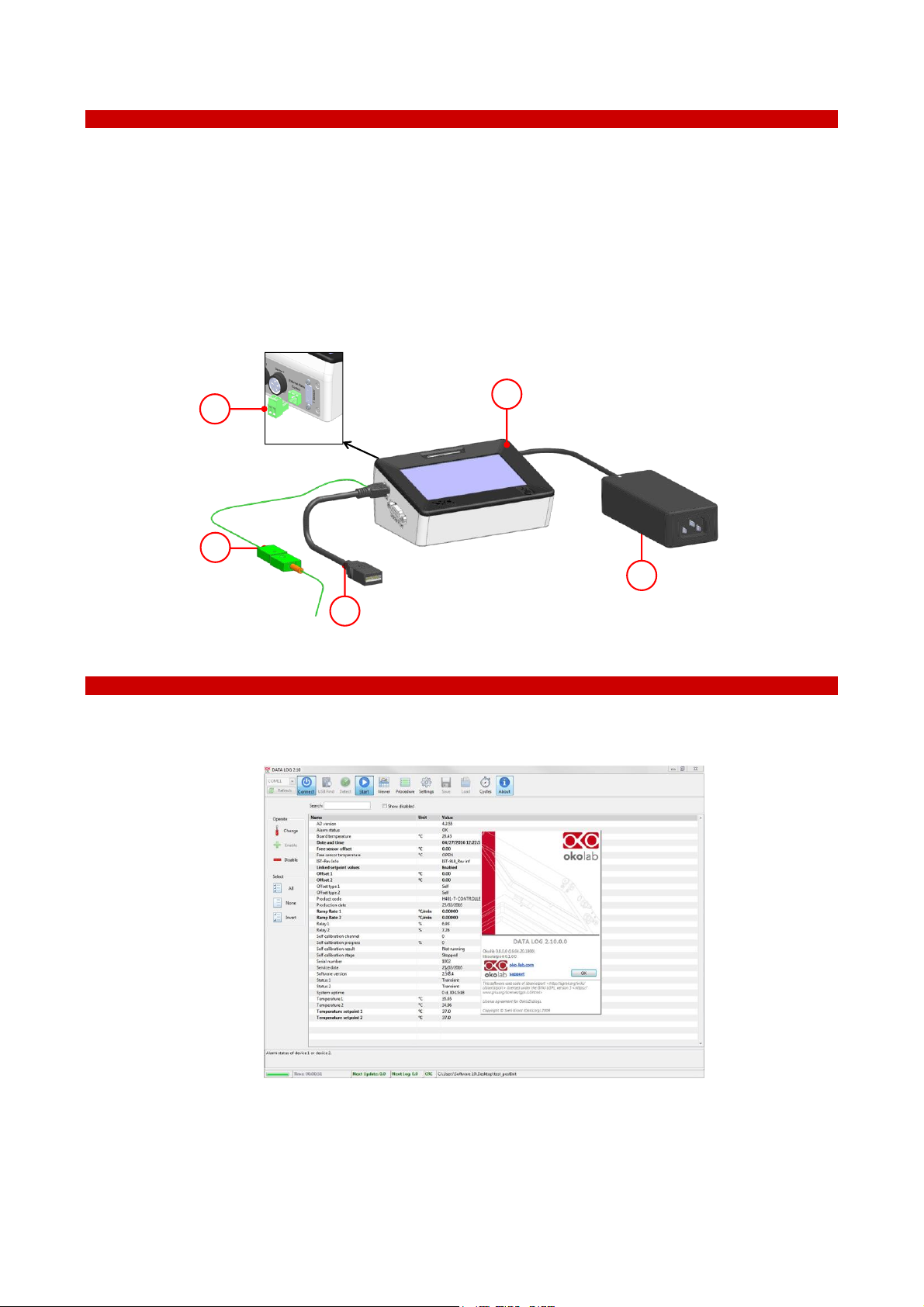
1 Controller. Dual channel temperature controller. See pointer 1 in Figure 1.
2 T Sensor. Fine gauge immersible thermocouple, which can be used to calibrate the heating devices
connected to the Controller and to meter temperature, as needed. See pointer 2 in Figure 1.
3 Power feeder and power cord. 24V DC-60 W power feeder. See pointer 3 in Figure 1.
4 MINI-USB-OTG. Mini USB OTG cable to connect a USB drive to the H401-T-CONTROLLER for data
download. See pointer 4 in Figure 1.
5 Alarm screw terminal. Contact closure alarm. See pointer 5 in Figure 1.
4
3
1
2
5
Figure 1. H401-T-CONTROLLER – Components.
5 Optional Equipment
1 DATA LOG (Optional-to be purchased separately). It is a program that allows to use in tethered mode or
to log any Okolab device using a PC.
Figure 2. DATA LOG software.
8
6 Equipment Description
The H401-T-CONTROLLER is a touch screen digital dual channel temperature controller and data log
device allowing temperature set up, control and logging of two separate heating devices. It is a compact and
effective solution to reliably maintain the desired temperature of the specimen right on the microscope stage
within the range 25-60°C. The H401-T-CONTROLLER allows to set two different temperatures for the two
devices.
The H401-T-CONTROLLER comprises the Temperature Controller and a miniaturized water / oil
immersible temperature sensor which allows to calibrate the heating devices with great accuracy, by providing
feedback from the temperature of the culture medium contained inside the dish. The heating devices must be
purchased separately.
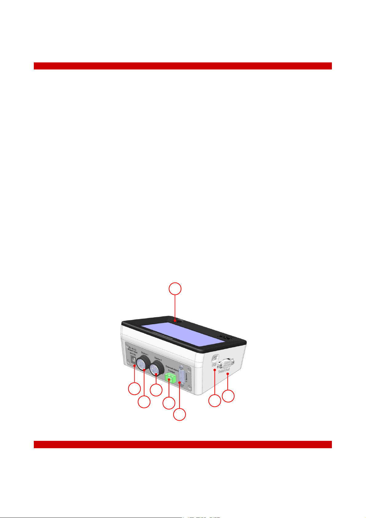
A detailed description of the H401-T-CONTROLLER is provided in the following list, which refers to the
pointers in Figure 3:
1 24 VDC Power Input
2 Device 1 port
3 Device 2 port
4 External Alarm Contact Closure
5 T Sensor port
6 Mini USB port
7 Serial port
8 Power switch
5
6
8
1
2
4
3
7
Figure 3. H401-T-CONTROLLER – Equipment description.
7 Installation
H401-T-CONTROLLER can control the temperature of up to two heating devices at the same time. Set
point temperature of the heating devices can be different.

9
7.1 Compatibility
H401-T-CONTROLLER is compatible with the following Okolab heating devices:
H401-T-GLASS series
H401-T-METAL series
H401-T-PAD series
H401-STAGE-T-PAD series
H401-GLASS-TABLE
OBJ-COLLAR-SERIES
For a complete list of compatible heating devices, refer to: www.oko-lab.com.
10
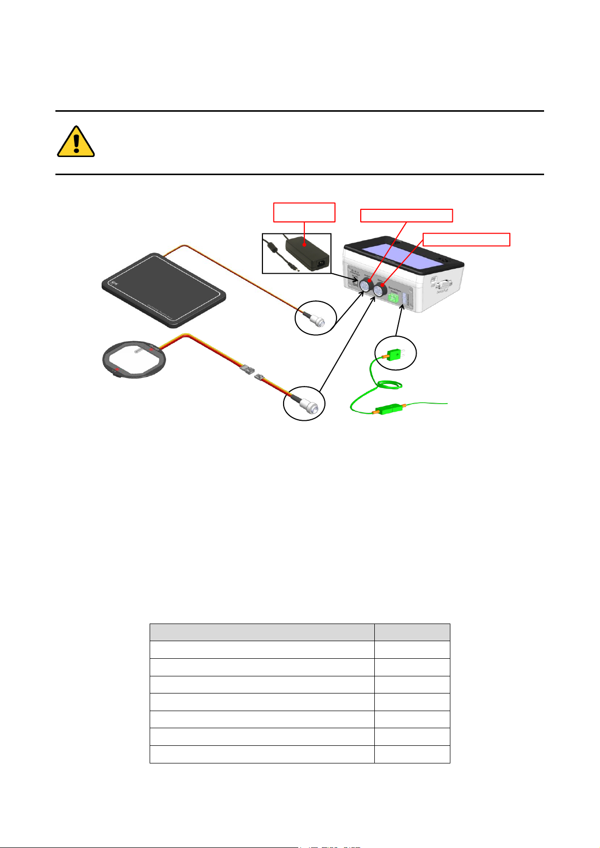
7.2 Connections of the heating devices
Do not turn on the device until you have completed and checked all connections.
Follow the instructions below to connect the heating devices to H401-T-CONTROLLER.
24 VDC
Power Feeder
Device1 Connector
Device2 Connector
Figure 4. Connection of the heating devices
1 Connect one heating device to the Device 1 connector on the rear panel of H401-T-CONTROLLER (see
Figure 4 and pointer 2 in Figure 3).
2 Connect the other heating device (if available) to the Device 2 connector on the rear panel of the H401-T-
CONTROLLER (see Figure 4 and pointer 3 in Figure 3).
3 Connect the T Sensor to the T Sensor connector on the rear panel of H401-T-CONTROLLER (see Figure 4
and pointer 5 of Figure 3).
4 Connect the Power Feeder to the Power Input (see Figure 4).
Tip ► Okolab provides the correct power adapter compatible with the devices configuration selected by
the user in the purchase order. The majority of configurations use a power adapter with Rating Power of 60
W. The configurations reported in Table 1 require a power adapter with Rating Power of 120 W.
Heating devices connected to the H401-T-CONTROLLER
Power required
#2 H401-T-PAD
120 W
#2 H401-GLASS-TABLE
120 W
#2 H401-T-STAGE-PAD
120 W
#1 H401-GLASS-TABLE+#1 H401-T-PAD
120 W
#1 H401-GLASS-TABLE+#1 H401-T-STAGE-PAD
120 W
#1 H401-T-PAD+#1 H401-T-STAGE-PAD
120 W
Any other configuration
60 W
Table 1. Heating devices that require power adapter with Rating Power 120 W.

11
Use only the power adapter provided by Okolab or a power adapter for the
recommended wattage, as reported in Table 1, to prevent system instability, random
reset, unexpected shutdown, or problems due to insufficient power.
For assistance, contact Okolab at support@oko-lab.com
Do not connect AC power supply to your device until you have completed all the
connections including the connection of the DC power supply cord to the rear panel of
the H401-T-CONTROLLER as shown in Figure 4
7.3 MINI-USB port
The MINI-USB port allows the H401-T-CONTROLLER to be connected with the outside world.
7.3.1 Connection of a USB drive
Use MINI-USB-OTG cable to connect a USB Drive (not supplied) to H401-T-CONTROLLER, as shown in
Figure 5.
USB Port
USB Drive
MINI-USB-OTG
Figure 5. USB drive connection.
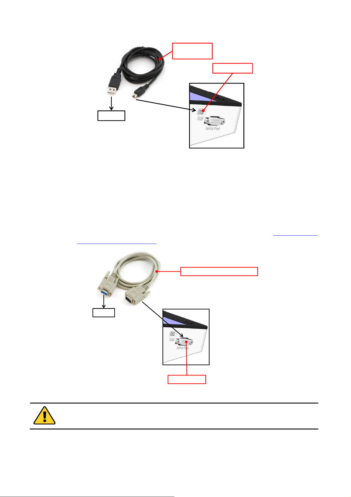
7.3.2 PC Connection via USB
Use a standard MINI-USB cable to connect H401-T-CONTROLLER to a PC, as shown in Figure 6. You can
communicate with H401-T-CONTROLLER via PC by using:
DATA-LOG software. The software allows to log and analyze the data provided by H401-T-
CONTROLLER via PC. Refer to DATA-LOG user manual for more info.
SDK (OKOLAB API) for integration in third party software http://www.oko-
lab.com/support#soft_int_tools.
12
USB Port
To PC
MINI USB
cable
Figure 6. PC connection via USB.
7.4 RS232 port – PC connection via RS232
Use a standard RS232 cable to connect H401-T-CONTROLLER to a PC as shown in Figure 7. This option
is advisable when the PC is at a distance greater than 10 meters from the H401-T-CONTROLLER.
You can interface with H401-T-CONTROLLER via PC by using:
DATA-LOG software. The software allows to log and analyze the data provided by H401-T-
CONTROLLER via PC. Refer to DATA-LOG user manual for more info.
SDK (OKOLAB API) for integration in third party software http://www.oko-
lab.com/support#soft_int_tools.
To PC
Serial Port
Serial Communication Cable
Figure 7. PC connection via RS232.
Without a serial port COM, to install the Serial Communication cable to your PC, you need to install
a USB to serial converter following the manufacturer instructions. If you want to log, you have to
use the COM port number that Windows assigned to the drive.
13
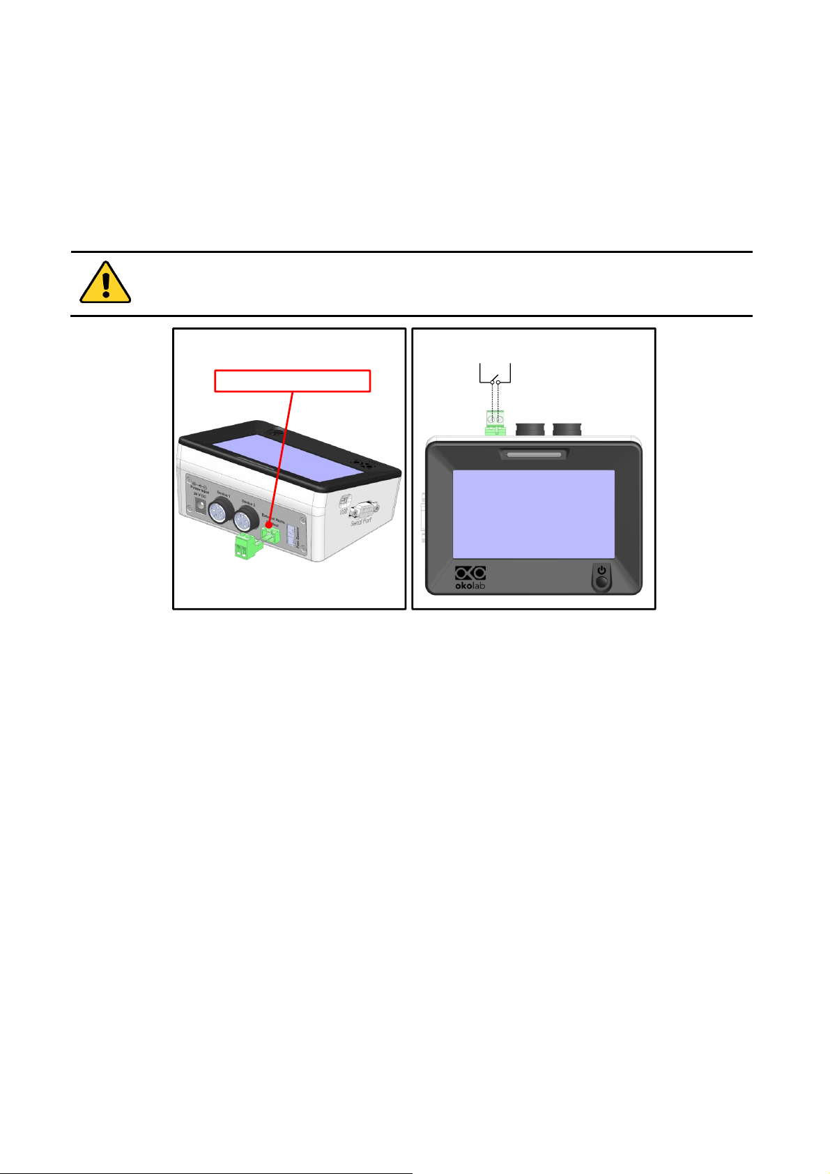
7.5 Alarm screw terminal
Connect the Alarm screw terminal to the real panel, as indicated in Figure 8(a).
Safety extra low voltage powered alarm equipment, not exceeding stated contact rating, may be
connected to the screw terminal. Refer to Figure 8(b) for alarm contact rating.
Tip ► The Screw Terminal is a contact closure alarm, which closes its circuit if H401-T-CONTROLLER
triggers on alarm.
The contact closure alarm does not close its circuit if H401-T-CONTROLLER is not powered.
2A max @ 30VDC
2A max @ 230VAC
Alarm Contact Closure
a b
Figure 8. Alarm contacts (a) Alarm Screw Terminal; (b) Contact rating.

14
8 User Interface
This chapter describes the user interface of the H401-T-CONTROLLER.
8.1 Homepage
Figure 9 shows the main control panel, in particular it highlights 16 pointers detailed below.
1 2 63 4 5 8
10
9
1112131516
17
18
19
20
7
14
Figure 9 Home page.
1 Device 1 status LED
2 Device 1 name (see 8.2.1.2 to learn how to input device name)
3 Device 1 image (see 8.2.1.1 to learn how to input the device type)
4 Device 1 temperature set point (see 8.1.1 to learn how to change the set point value)
5 Device 1 temperature current value
6 Device 2 name
7 Device 2 image
8 Device 2 temperature current value
9 Device 2 status LED
10 T Sensor current value
11 Support. Touch here to learn how to contact OKOLAB
12 Device 1 and Device 2 min/max temperatures within the time-frame set in the Options subpage
13 PC connection
14 Internal memory logging icon
15 Calibration summary
16 Display mode. Touch here to switch display mode
17 Overview page
15
18 Settings. Press here to access system options and settings
19 Home. To open the homepage
20 Product info. Press here to know generic info about H401-T-CONTROLLER and running time
Note 1 ► The H401-T-CONTROLLER allows to set different temperature set points for the two heating
devices. See paragraph 8.2.1.1 for more info.
Tip 1 ► The Touch Screen is pre-set with a set point Temperature of 37°C. Once turned on it will start
operating to reach this set-point value.
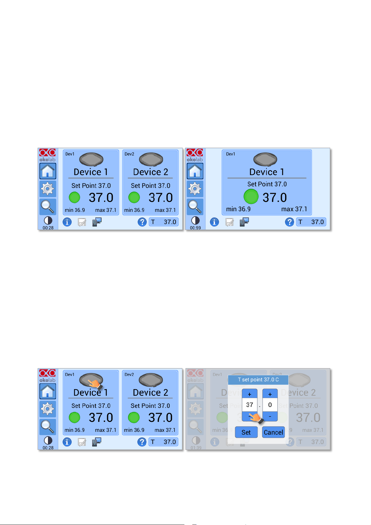
Note 2 ► Homepage will appear as in Figure 10(a) if the two heating devices are connected and as in
Figure 10(b), if only one device is connected.
a b
Figure 10. Home Page. (a) Two devices connected; (b) One device connected.
Each rectangle reports the temperature set point of the device, its current temperature value and the
minimum (on the left) and maximum (on the right) temperature values reached within a defined time frame,
previously selected by the operator, as reported in paragraph 8.2.5.1.
A status indicator (colored dot) is reported on the left of the current temperature. In this example the
status indicator is green. The color of the status indicator changes according to the status of the controller. See
paragraph 8.1.2 for a description of the possible controller status and of the relative color assumed by the status
indicator.
8.1.1 How to enter the set point temperature
To input a new set-point temperature for a heating device, touch the corresponding tab, as indicated in
Figure 11 (a).
a b
Figure 11. Definition of the set point. (a) Selection of the device; (b) Input of the set point value.
16
The set point regulation page will appear as in the Figure 11 (b). You can modify the set point by clicking
on + and –. Once you have input the new set point temperature, press Set to save or Cancel to undo.
Tip 2 ► After any change in the set point value the controller enters into a transient regime, the Status
Indicator and the Top LED turn yellow (see paragraph 8.1.2). During the transient regime, the controller
will not trigger on alarm. The maximum length of the transient regime is set by the operator as indicated in
paragraph 8.2.4.
8.1.2 Controller Status: colours and meaning
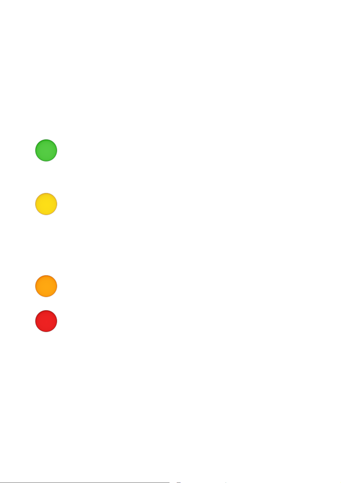
The H401-T-CONTROLLER can assume four different status, which are represented by the colors
assumed by the Status Indicator (pointer 1 in) and by the TOP LED (if enabled, as indicated in paragraph 8.2.5.5):
The GREEN color indicates that the set-point value has been reached (within the
tolerance defined in the alarm subpage, see paragraph 8.2.4) and that the system is working
properly.
Controller Status: NORMAL
The YELLOW color indicates that the controller is in transient regime. The Yellow light
will appear after the controller is turned on and after any set point chance. The system is working
properly, it is not in alarm and no action is needed. As soon as the H401-T-CONTROLLER
stabilizes the temperature of the heating devices, the Controller Status changes to NORMAL and
the color turn GREEN. If the H401-T-CONTROLLER cannot stabilize the temperature of one or
both heating devices within the maximum time defined by the operator (see paragraph 8.2.4), the
Controller Status changes to ALARM and the color turn ORANGE.
Controller Status: TRANSIENT
Note ► If two heating devices are connected to the controller and the set point of only one is changed, the
corresponding LED turns yellow and other LED remains green. The controller enters in transient regime
and will not trigger in alarm for both devices.
The ORANGE colour indicates that the current Temperature value is out of the tolerance
defined in the alarm subpage (see paragraph 8.2.4). The controller triggers in Alarm.
Controller Status: ALARM
The RED color indicates that there is a problem with the unit itself (for example a
Temperature sensor is broken). The system is in alarm. Turn the system off, wait for 5 minutes,
and turn it back on. If the color is still red, contact Okolab at www.oko-lab.com for support.
Controller Status: ALARM
Note 3 ► If the heating device is not properly connected to the H401-T-CONTROLLER, the colour of the
Status Indicator and of the Top LED turns red and the text OPEN appears. If you have only one heating
device, make sure that the channel not connected to any heating device is disabled, as indicated in
paragraph 8.2.1.1.
Tip 3 ► The Top LED (see Figure 12) follows the same color code as the status LED.
To activate the Top LED, follow the instructions reported in paragraph 8.2.5.5.
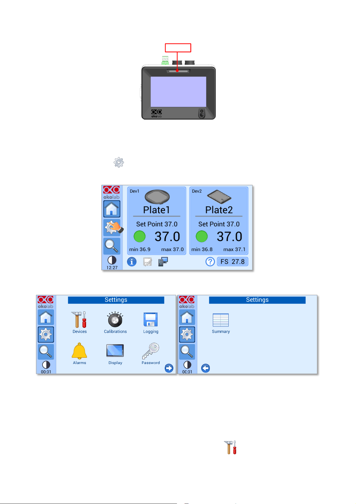
17
Top LED
Figure 12. Top LED.
8.2 Settings
Press on Settings icon to enter the Settings menu, as shown in Figure 13. The settings menu has 7
items, as shown in Figure 14.
Figure 13. How to enter in the Settings menu
Figure 14. Settings Menu
8.2.1 Device configuration
The Device menu allows the definition of the types of heating devices connected to the H401-T-
CONTROLLER as well as the definition of a label and of the maximum heating rate for each device.
To enter in the Device Configuration menu, press on Devices icon , as indicate in Figure 15(a). The
Device Configuration menu contains three icons as shown in Figure 15(b).
 Loading...