

Page 1

1
H301-T-UNIT-BL-PLUS
Electric Top Stage Incubation System
Manual
Vers. 01.17
Page 2

2
This page was left blank
Page 3

3
Index
INDEX
1 PREFACE ............................................................................................................................................................ 5
2 SYMBOLS DESCRIPTION .................................................................................................................................... 6
2.1 Symbols in this manual and on the product ............................................................................... 6
2.2 Symbols on the product label ................................................................................................ 6
3 SAFETY NOTES .................................................................................................................................................. 7
4 SYSTEM OVERVIEW ........................................................................................................................................... 9
4.1 Equipment supplied ............................................................................................................ 9
4.2 Equipment not supplied ....................................................................................................... 9
4.2.1 Equipment Required ........................................................................................................ 9
4.2.2 Optional ...................................................................................................................... 9
4.3 Temperature Controller connection ports ............................................................................... 10
5 H301-T-UNIT-BL-PLUS. INSTALLATION AND USER GUIDE ......................................................................... 10
5.1 H301-T-UNIT-BL-PLUS. Installation guide ................................................................................ 10
5.2 How to connect H301-T-UNIT-BL-PLUS to a BOLD LINE Digital Gas Controller .................................... 13
6 USER INTERFACE ............................................................................................................................................. 15
6.1 Home page .................................................................................................................... 15
6.1.1 Colors meaning ............................................................................................................ 15
6.1.2 Changing Set Points....................................................................................................... 16
6.2 Settings ........................................................................................................................ 16
6.2.1 Temperature ............................................................................................................... 16
6.2.1.1 Chamber/Adapter ............................................................................................................. 16
6.2.1.2 Control Mode ..................................................................................................................... 17
6.2.1.3 Objective Heater .............................................................................................................. 21
6.2.1.4 Thermal Cycles .................................................................................................................. 24
6.2.1.5 Open Incubator ................................................................................................................. 26
6.2.1.6 Ramp Rate .......................................................................................................................... 27
6.2.1.7 External Sensors ................................................................................................................ 27
6.2.1.8 Status .................................................................................................................................. 28
6.2.1.9 Digital Input ....................................................................................................................... 28
6.2.2 Touch Screen .............................................................................................................. 29
6.2.2.1 Options ............................................................................................................................... 29
6.2.2.2 Brightness ........................................................................................................................... 30
6.2.2.3 Calibration ......................................................................................................................... 30
6.2.2.4 Date & Time....................................................................................................................... 30
Page 4

4
6.2.2.5 Alarms ................................................................................................................................. 31
6.2.2.6 Visual Effects ..................................................................................................................... 31
6.3 Overview Page ................................................................................................................ 32
6.4 Glance Mode .................................................................................................................. 32
7 CALIBRATIONS ................................................................................................................................................. 34
7.1 Chamber Self-Calibration ................................................................................................... 34
7.2 Objective Heater Manual Calibration ..................................................................................... 35
7.3 Objective Heater Self-Calibration ......................................................................................... 37
8 MAINTENANCE ................................................................................................................................................. 39
9 SUPPORT .......................................................................................................................................................... 40
9.1 QR Codes for Support ........................................................................................................ 40
9.2 Support Contacts ............................................................................................................. 40
9.3 Web Conference For Assistance And Training ........................................................................... 40
10 TROUBLESHOOTING .................................................................................................................................. 42
11 TECHNICAL SPECIFICATIONS ................................................................................................................... 43
12 FIGURE LIST ............................................................................................................................................... 44
13 REVISION TABLE ........................................................................................................................................ 45
Page 5

5
1 PREFACE
H301-T-UNIT-BL-PLUS is a temperature controller that can operate any Okolab Electrically Heated Stage
Top Incubator to maintain the required thermal conditions for live cell imaging right on the microscope
stage. H301-T-UNIT-BL-PLUS is compatible with Okolab Objective Heaters and Digital Gas Controllers to
maintain the sample in physiological condition with the highest accuracy, thus allowing long term time lapse
imaging.
H301-T-UNIT-BL-PLUS controls the temperature of the incubator base and lid and, when connected, of the
Objective Heater. To improve accuracy on sample temperature, H301-T-UNIT-BL-PLUS is equipped with a
flexible fine gauge thermocouple that can be used to provide feedback from the temperature of a reference
well located in close proximity to the experimental sample. H301-T-UNIT-BL-PLUS is equipped with a room
temperature sensor to monitor laboratory temperature.
H301-T-UNIT-BL-PLUS can be operated via the convenient touch screen interface OKO-TOUCH (not
included), via OKOLAB DataLog Software or via any Third Party Software.
Page 6
6
2 SYMBOLS DESCRIPTION
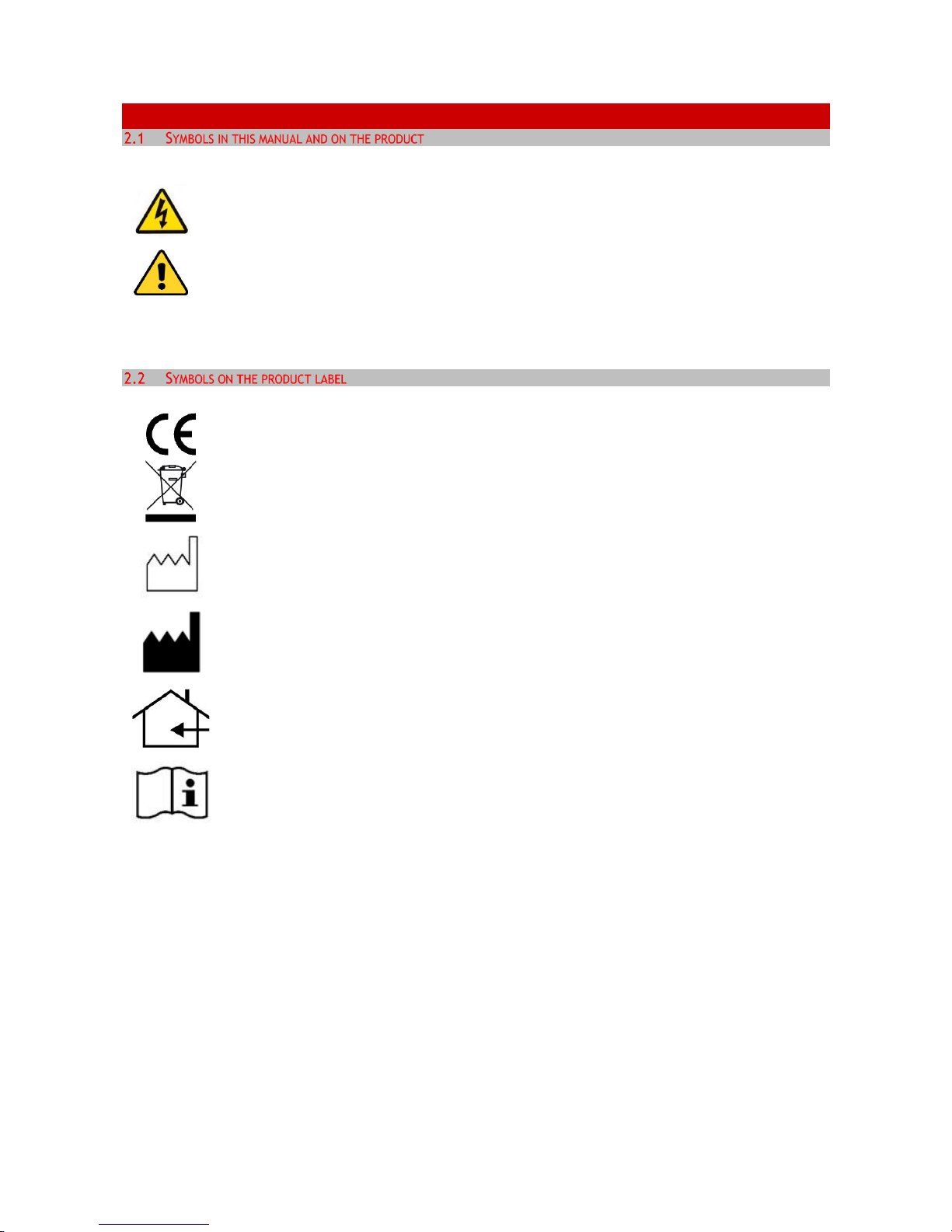
The following symbols identify important information to note:
CAUTION or WARNING: This symbol warns you about the risk of electrical shock.
CAUTION or WARNING or IMPORTANT: This symbol warns you of circumstances or practices
that can affect the instrument’s functionality. Please refer to accompanying documents.
Tip - Supplies you with helpful suggestions.
Note - Supplies you with important information to successfully setup and use the instrument.
CE MARKING: This symbol indicates a product’s compliance with EU legislation.
PRODUCT DISPOSAL: This symbol indicates that this product must not be disposed as urban
solid waste.
This symbol indicates the product production date
This symbol indicates the manufacturer data
This symbol indicates the protection degree against ingress of solids or liquids inside the
product.
This symbol warns you to read the user manual before starting the device
Page 7
7
3 SAFETY NOTES
Before operating the equipment please read carefully the instructions and the safety notes. If you have any
questions, please contact Okolab.
The equipment must only be used as intended and as described in this Manual.
Equipment should only be operated by technically qualified personnel.
Do not start up the equipment if some of its parts are damaged.
This instrument is not intended for use in locations where flammable or explosive gases are
present.
Handle the equipment with care.
Equipment and its internal parts can be damaged by dropping and by shock.
Do not use a volatile solvent such as paint thinner to clean the instrument. Deformation or
discoloration will occur. Use a soft, dry cloth to remove stains from the instrument. Not
following these instructions can result in damage or breakdown of the device and its
accessories.
The products labels can be found on the bottom panel of the Main Unit.
Do not exceed voltage indicated in this manual and on the product label.
Avoid excessive induction noise, static electricity, magnetic fields.
Do not expose this instrument to rain or moisture.
Prevent throttling and kinking of tubing.
Check the cables are well fixed to their own connectors so they cannot slip off
This device is not designed for use under medical conditions.
Power cord of unit should be unplugged from electrical outlet when left unused for long period
of time.
VENTILATION, unit should be situated so that its' location or position does not interfere with
proper ventilation.
Unit should be situated away from heat sources such as radiators, heat registers,
stoves, or other appliances or processes that produce heat
Do not start up the equipment if the supply cable is damaged.
Connect the equipment only to grounded mains power socket.
Do not disconnect cables while in operation.
Do not open the unit. Do not remove cover or back.
Page 8
8
Prevent metal fragments or lead wire scraps from falling inside instrument case to avoid
electric shock, fire or malfunction.
No user serviceable parts inside.
Before starting, assemble the equipment while unplugged from an outlet.
Unit should never be used where it can fall or be pushed into water.
International caution symbol marks this device. IMPORTANT: read the “Safety Notes”
before installing, using and commissioning this device, as the notes contain important
information relating to safety and EMC. Not following these instructions can result in
damage or breakdown of the device and its accessories.
We reserve the right to make technical variations.
IN NO EVENT SHALL OKOLAB S.R.L. BE LIABLE FOR ANY DIRECT, INCIDENTAL OR CONSEQUENTIAL DAMAGES
OF ANY NATURE, LOSSES OR EXPENSES RESULTING FROM ANY DEFECTIVE PRODUCT OR THE USE OF ANY
PRODUCT.
Page 9
9
4 SYSTEM OVERVIEW
H301-T-UNIT-BL-PLUS includes:
1. T-Unit
2. Fine Gauge Thermocouple. To measure specimen temperature
3. NTC Thermistor. To measure ambient temperature
4. #1 24V-DC Power Adapter
4.2.1 Equipment Required
• Okolab incubating chamber with heated lid and base, chamber riser with one or more plate
adapters
4.2.2 Optional
• OKO-TOUCH, including:
1. Touch Screen Interface
2. #1 5V-DC Power adapter. To connect the Touch Screen.
3. #1 RS232 Serial cable. To connect the Touch Screen to the T-Unit
• Objective heater. Required ONLY when using immersion or dipping objectives.
Page 10
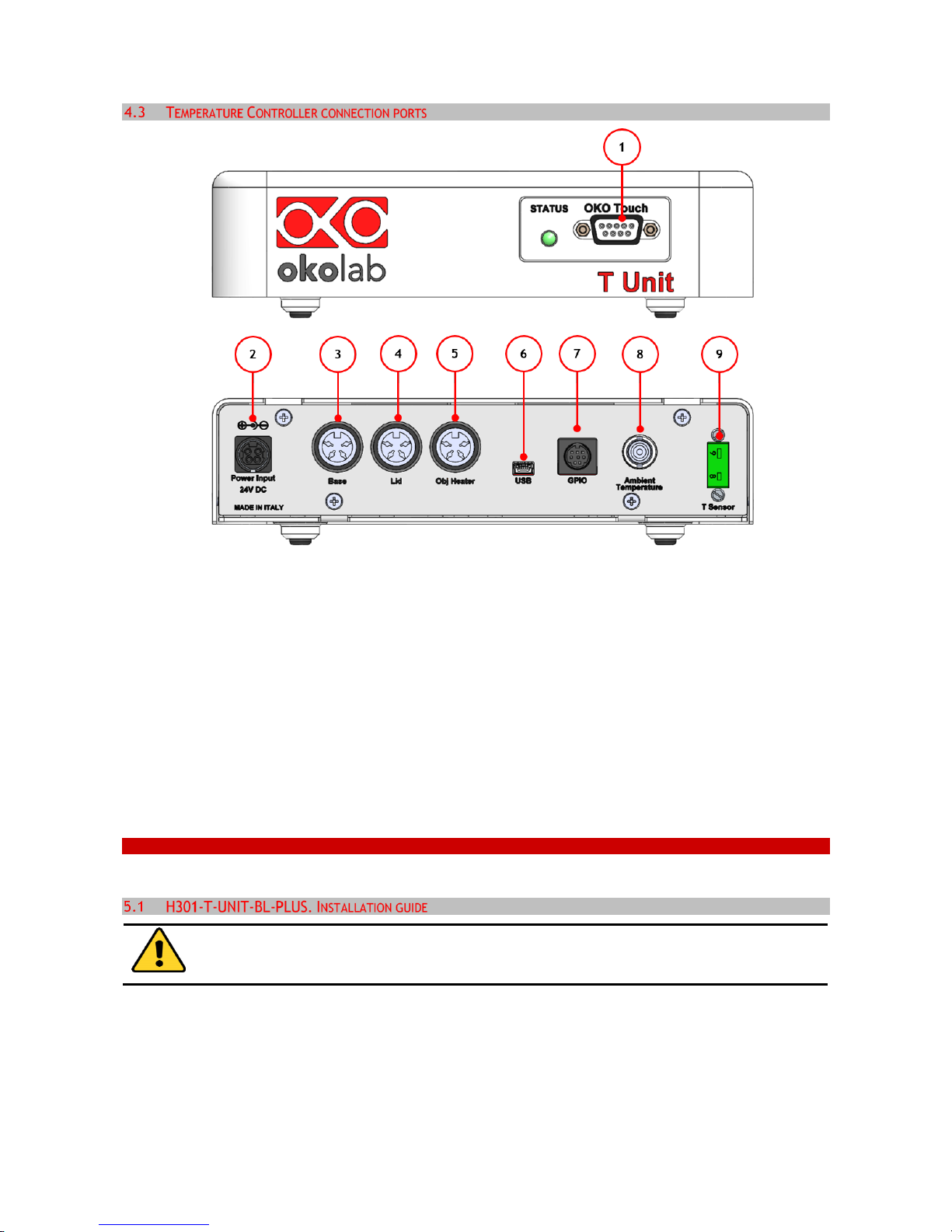
10
Figure 1: Control Unit Rear Panel Overview
1. OKO-TOUCH RS232 serial port.
2. Power Input.
3. Chamber base connector.
4. Lid chamber connector.
5. Objective Heater connector (only if you have ordered also an OBJ-COLLAR-####)
6. USB port.
7. General Purpose Input Output (GPIO) port.
8. NTC Thermistor port.
9. Gauge Thermocouple port.
5 H301-T-UNIT-BL-PLUS. INSTALLATION AND USER GUIDE
The following paragraphs illustrate how to install and use the Temperature Control Unit.
The following instructions will guide you through a quick installation. For safe operation of the
unit it is absolutely necessary to read carefully all the instructions and safety notes.
Page 11
11
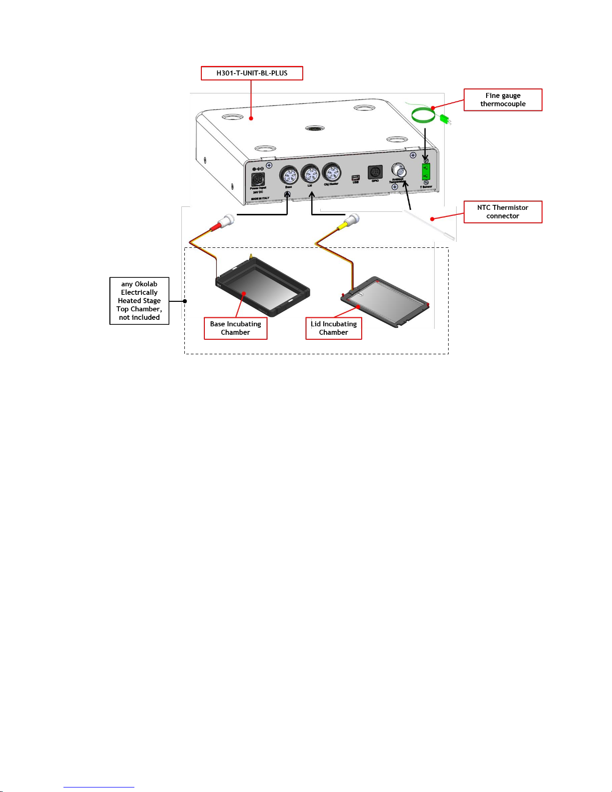
Figure 2. H301-T-BL-PLUS. Standard Connection
1. Connect the base of the incubation chamber to the port labeled ‘Base’ on the rear panel of the
Temperature Control Unit (see Figure 2).
2. Connect the lid of the incubation chamber to the port labeled ‘Lid’ on the rear panel of the
Temperature Control Unit (see Figure 2).
3. Plug the NTC Connector on the port labeled ‘Ambient Temperature’ located on the rear panel of the
Temperature Control Unit (see Figure 2). This temperature sensor must be placed in air close to the
illumination pillar in proximity to the microscope stage. This thermistor is monitoring the room
temperature.
Note ► Stage Top Chambers for most brands/models are available. See www.oko-lab.com for details.
4. The Fine Gauge Thermocouple (green) plugs into the green port labeled ‘Reference Temperature’
located on the rear panel of the Temperature Control Unit (see Figure 2). When operating the device
in ‘Sample Feedback Mode’ place this thermocouple in a Reference Well filled with water. Make sure
that the end of the Fine Gauge Thermocouple is fully immersed.
Tip ► The Fine Gauge Thermocouple may be placed into a Reference Well if running the “Sample Feedback
Mode” (see paragraph 6.2.1.2). The Fine Gauge Thermocouple may also be used to calibrate the Stage
Top Incubation Chamber and/or the Objective Heater (OBJ-COLLAR ####), when present. The Fine
Gauge Thermocouple may be left in air if the system is operated in ‘Chamber feedback mode’ (see
paragraph 6.2.1.2)
Page 12
12
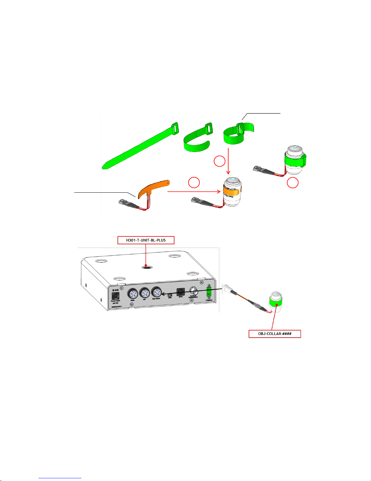
5. When using oil immersion objectives an Objective Heater should also be purchased. If your system is
also equipped with the Objective Heater, (OBJ-COLLAR ####, optional) its objective collar should be
installed before connecting the heater to rear panel of the Temperature Control Unit. Follow the
steps shown in Figure 3. Once you have assembled it, plug it into the port labeled ‘Obj. Heater’
located on the rear panel of the Temperature Control Unit (see Figure 4).
Figure 3.Objective Heater (OBJ-COLLAR ####) Assembly
Figure 4. OBJ-COLLAR Connection (Optional)
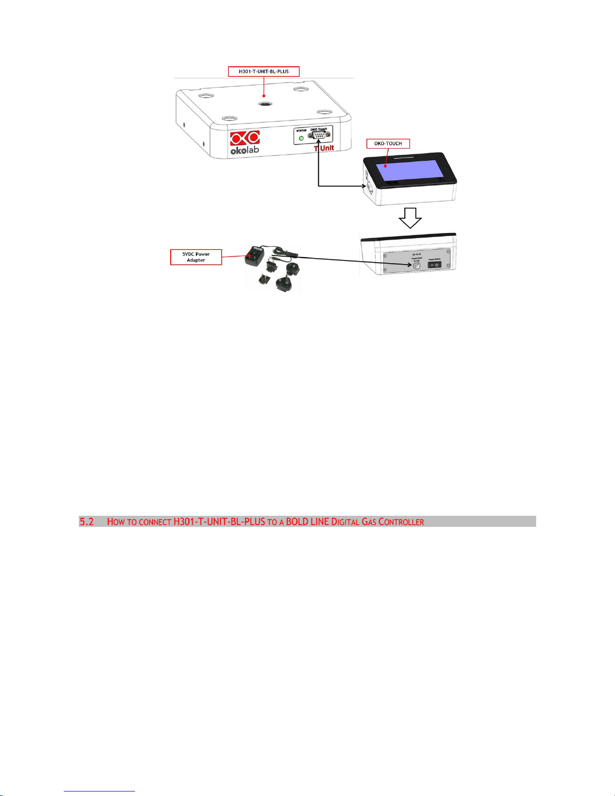
6. Connect the touch screen interface OKO-TOUCH to the Temperature Control Unit using the serial
cable provided (see Figure 5).
2
1
3
Objective Band Heater
Velcro Tape
Page 13
13
Figure 5. OKO-TOUCH Connection
7. Connect the power adapter to OKO-TOUCH. Connect the additional power cord to the Temperature
Control Unit.
8. Turn the OKO-TOUCH on (rocking switch is located on the back panel of OKO-TOUCH). A small green
LED light will blink on the front of the Temperature Control Unit. This means that the system is
initializing.
Once the system has been initialized the LED on the Temperature Control Unit will no longer blink and will
be steadily on. The OKO-TOUCH interface will display its homepage and the indicator light on the
temperature tab will be initially yellow. When the temperature set-point is within the set tolerance range,
the indicator light will turn green.
Tip ►Wait until system has reached the steady state before loading your samples.
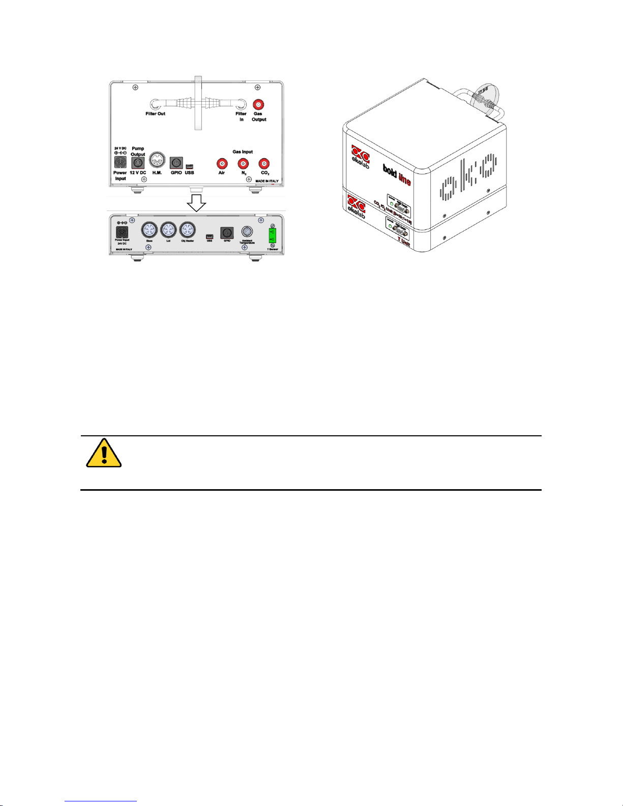
The H301-T-UNIT-BL-PLUS can be used as a stand-alone device or in combination with any one of the Bold
Line Gas Controllers. Figure 6 shows how to assemble the H301-T UNIT-BL-PLUS, for example, with a CO2-
O2 Unit BL [0-10; 1-18].
Page 14
14
a. CO2-O2 UNIT-BL [0-10; 1-18] and
H301-T-UNIT-BL-PLUS. Units rear panels.
b. CO2-O2 UNIT-BL [0-10; 1-18] and
H301-T-UNIT-BL-PLUS. 3D view.
Figure 6. CO2-O2 UNIT-BL [0-10; 1-18] and H301-T-UNIT-BL-PLUS
The T-Unit must stack on top of the Gas Controller by lining up the bus ports located on the top and bottom
surface of each. When the units are properly connected the Temperature, CO2 and O2 parameters will
appear on the OKO-TOUCH Touch Screen interface Home page. If not all the parameters appear on OKO-
TOUCH Home Page then the Control Units are not properly connected. Please check that the bus ports are
properly aligned with each other.
If you have a Gas Controller and a Temperature Control Unit, it is essential to read both this
manual and the Gas Controller Manual to familiarize yourself with the functions and the
operation of the devices before use.
Page 15
15
6 USER INTERFACE
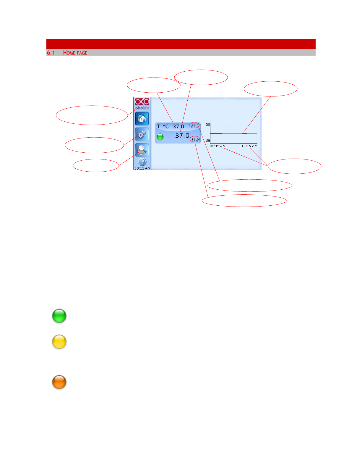
Figure 7. Homepage of the Control Unit Touch Screen Display
On the right side of the screen you will see the graph of Temperature value over time. The X axis displays
the scale of the duration of time you selected (in this example 1 hour). The Y axis, shows the temperature
scale.
Tip ►The Touch Screen is pre-set at the following temperature: 37°C. Once turning the Touch Screen on it
will start operating to reach this set-point value.
6.1.1 Colors meaning
The GREEN indicator means that set-point value has been reached (within the tolerance
you’ve set) and that the system is working properly.
The YELLOW indicator means that the system is working towards reaching set points. NO
actions on your part are required. The Yellow light will also appear every time you change
the Temperature set-point.
The ORANGE indicator means that the current gas concentration is not correct and its value
is out of the set tolerance (see section “ALARMS” in paragraph 6.2.2.5). While giving time to
the system to recover from this out-of-range value, please double check if there may be
reasons not depending on the unit for which it is not properly working. Verify if all cables are
correctly connected.
Maximum T °C reached within the time-period
Temperature set-point
Touch here to access system
options and settings
Touch here to go to
the OVERVIEW page
Current
Temperature value
Chart history lenght
set at 1 h
Temperature chart
Minimum T °C reached within the time-period
Touch here to know
generic info about Control
Unit and running time
Page 16
16
The RED indicator means that there could be a problem with the unit. If after 20-30 minutes
the Red light does not turn to Green, turn the system off, wait 5 minutes and turn it back on.
If the problem persists contact Okolab at http://www.oko-lab.com
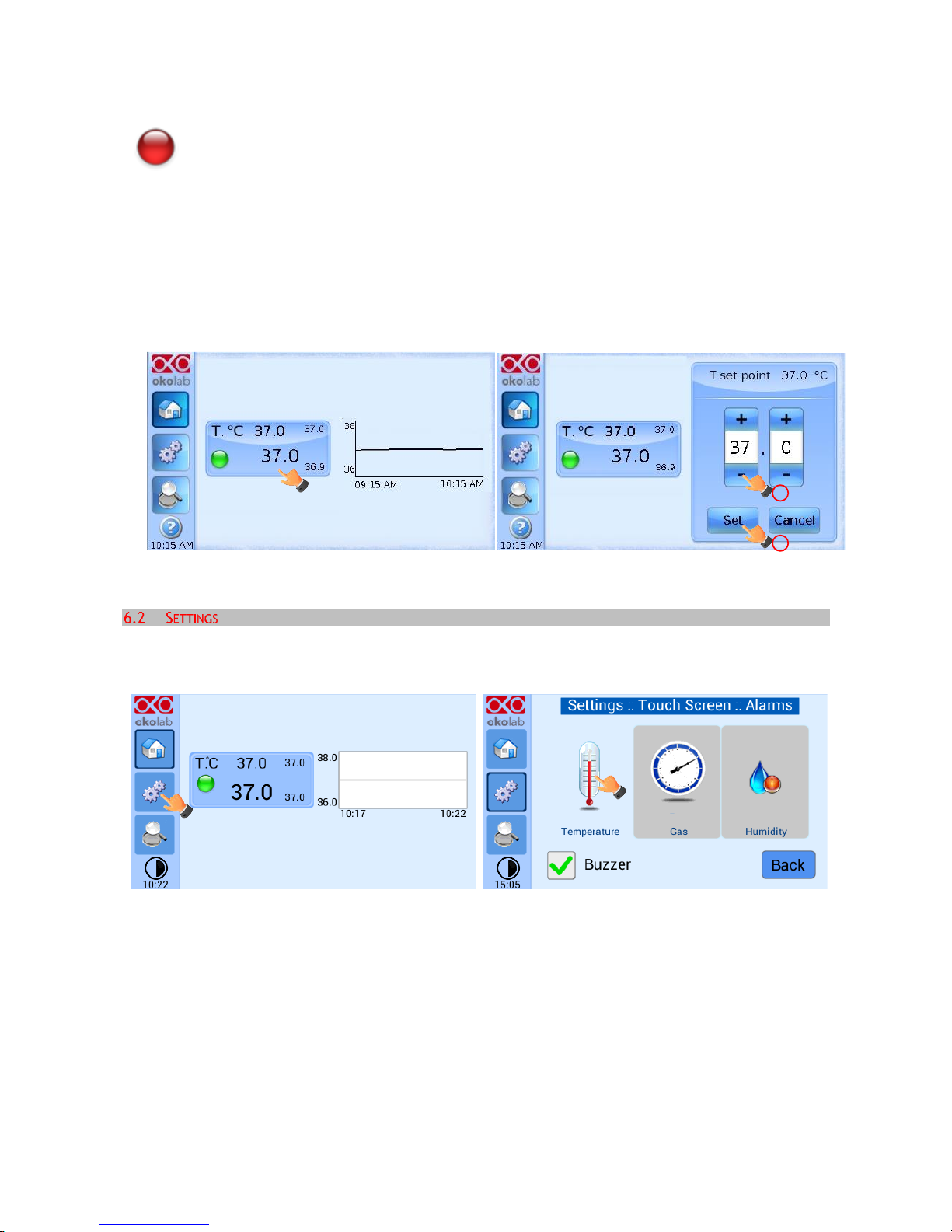
6.1.2 Changing Set Points
To change a set point, simply touch the corresponding tab. A new page will open where you can press +/–
to adjust the temperature to the desired value from 3°C above ambient to 60°C. Press “Set” to save the
new set point or “Cancel” to undo.
Figure 8. How to change the Temperature set point
6.2.1 Temperature
Temperature Settings are adjusted by following the two steps below (look at the touching finger)
Figure 9. Temperature settings
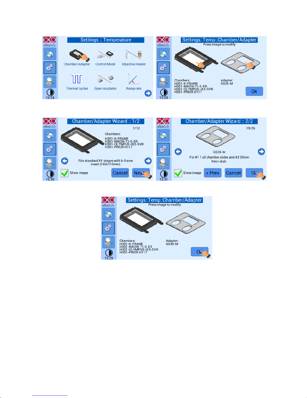
6.2.1.1 Chamber/Adapter
Figure 10. Here you have to set the model of incubating chamber (it depends on your XY stage/piezo) that
you have purchased and the type of sample adapter being inserted into it. Depending on these selections,
the thermal controller will automatically change settings. To switch configuration press on the Chamber or
on the Adapter icon (see Figure 10), then scroll among different chambers/adapters using the arrows on the
left and right sides of the screen. If you choose to change the chamber, when the chamber you are about
to use appears on the screen press “Next”. Repeat this sequence to find and select the sample adapter (see
Figure 11) and press “Ok” (see Figure 12). The unit will save these settings.
1
2
Page 17
17
Figure 10. Chamber & Adapter change
Figure 11 Chamber & Adapter settings
Figure 12. Chamber and adapters saving
Tip ►The system is shipped from the factory already set according to the incubating chamber model and
sample adapter you have ordered. Keep in mind that thermal control settings change when changing the
adapter in use. Hence, every time you change adapter you must input the correct one using the procedure
above. In case you purchase additional incubating chamber models make sure to input the correct
chamber/sample insert in the Setting prior to your experiment.
6.2.1.2 Control Mode
The Temperature Control can run in two different modes, please choose which one you want to use, Sample
or Chamber Feedback Mode.
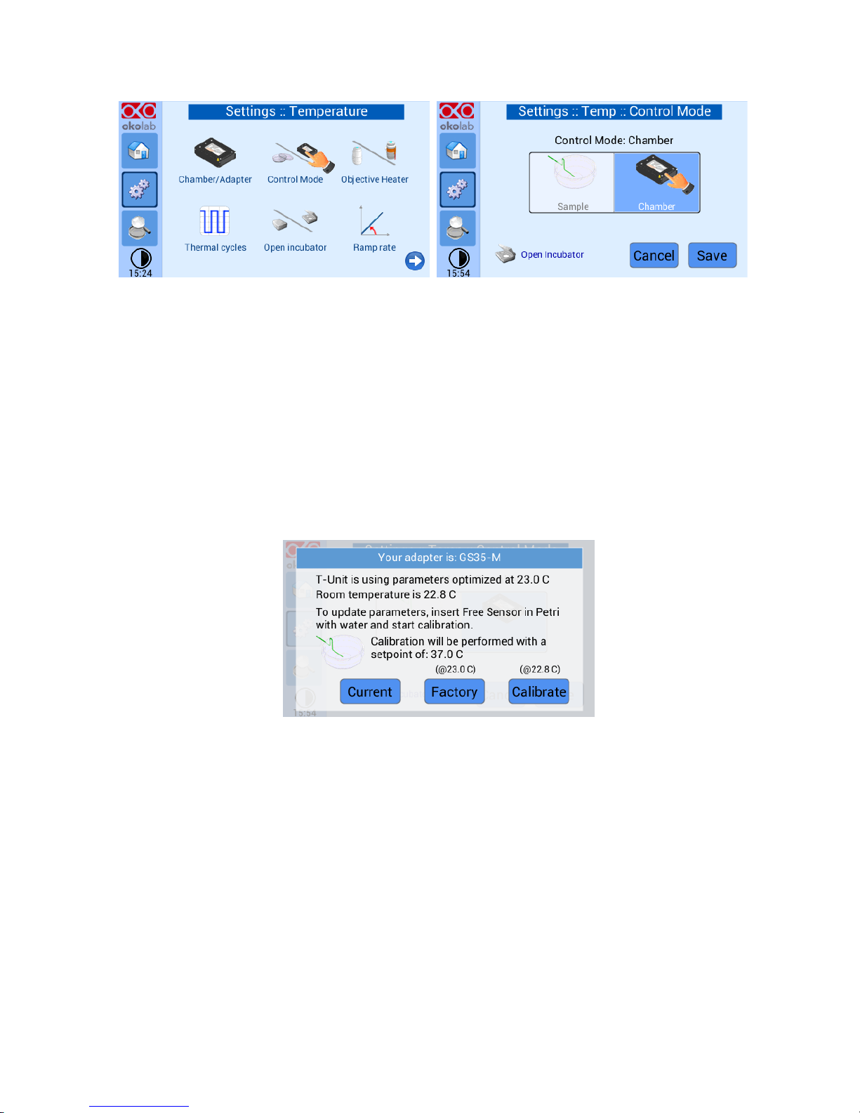
Figure 13 shows how to select Chamber Feedback Mode.
Page 18
18
Figure 13. Chamber Mode Setting
In this configuration the temperatures of both the lid and the base of the incubating chamber are strictly
controlled. A careful calibration performed in our laboratories between these temperatures and that of the
sample, guarantees that sample temperature is maintained at the desired set point value. The advantage
of this solution is that you don’t have to manually place the Fine Gauge Thermocouple into a Reference
Well.
Tip ► Advantages of this Control Mode are: fast experiment start up and no specific action required in multi
user applications. The disadvantage is that it needs calibration in case of room temperature variations
beyond +/- 1 degree Celsius.
When selecting Chamber Feedback Mode the following Screen will appear:
Figure 14. Chamber calibration start
It states that the system has been calibrated at the factory at a Room Temperature of 23°C. In case your
Room Temperature, measured by the included thermistor, is different from 23°C (i.e. 20.3°C) you have 3
options:
1. Use Current Calibration: this means recalling the last saved calibration settings. Once you calibrate
the system (see point 3 below) these settings will be automatically stored. The system saves only
the last calibration performed. Please note that calibration depends on i) set-point temperature; ii)
room temperature; iii) type of sample adapter in use. Hence using ‘Custom Calibration’ is NOT
recommended in any of the following as it will yield inaccurate results:
A. If the recalled calibration was performed with a different sample adapter than what you intend
to use
B. If the room temperature on the Custom Calibration is significantly different than the current one
(i.e. more than 1°C)
Page 19
19
C. If the Custom Calibration was performed with a different set point temperature than what you
plan on using (e.g Custom Calibration had set point of 37C but new experiment requires a set point
temperature of 39C).
2. Use Factory settings optimized at 23°C Room Temperature. This is acceptable if your room
temperature is within 1°C from 23°C. However, for room temperature more than 1°C from 23°C this
may be not acceptable depending on the sensitivity of your sample.
3. Choose to Calibrate the system in your lab at your Room Temperature, for maximum of accuracy
when using “Chamber Feedback Mode”. To do so follow the instructions on paragraph 7 (Chamber
Self-Calibration) and then press the “Calibrate” button; the automatic calibration procedure will
start.
Tip ► Note please it may take 1-2 hours to complete the calibration.
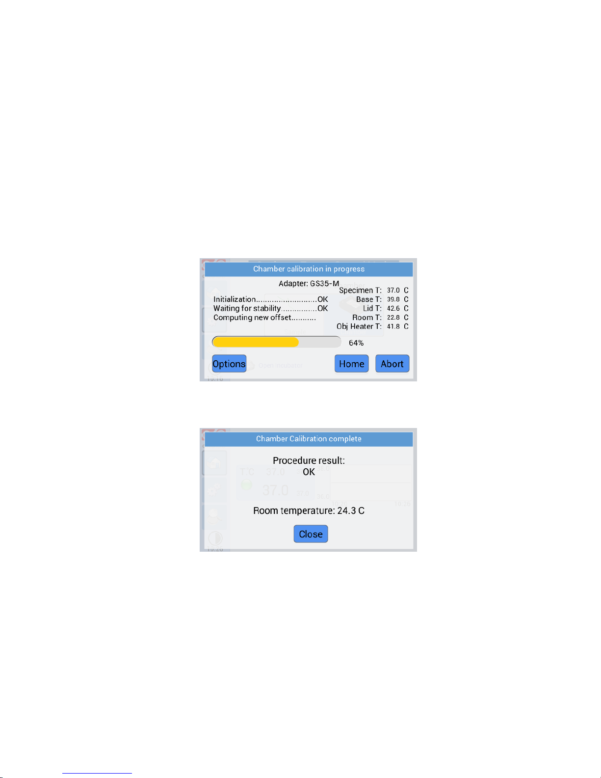
Figure 15. Chamber calibration progress
Just wait until the following dialog box appears:
Figure 16. Chamber Calibration result
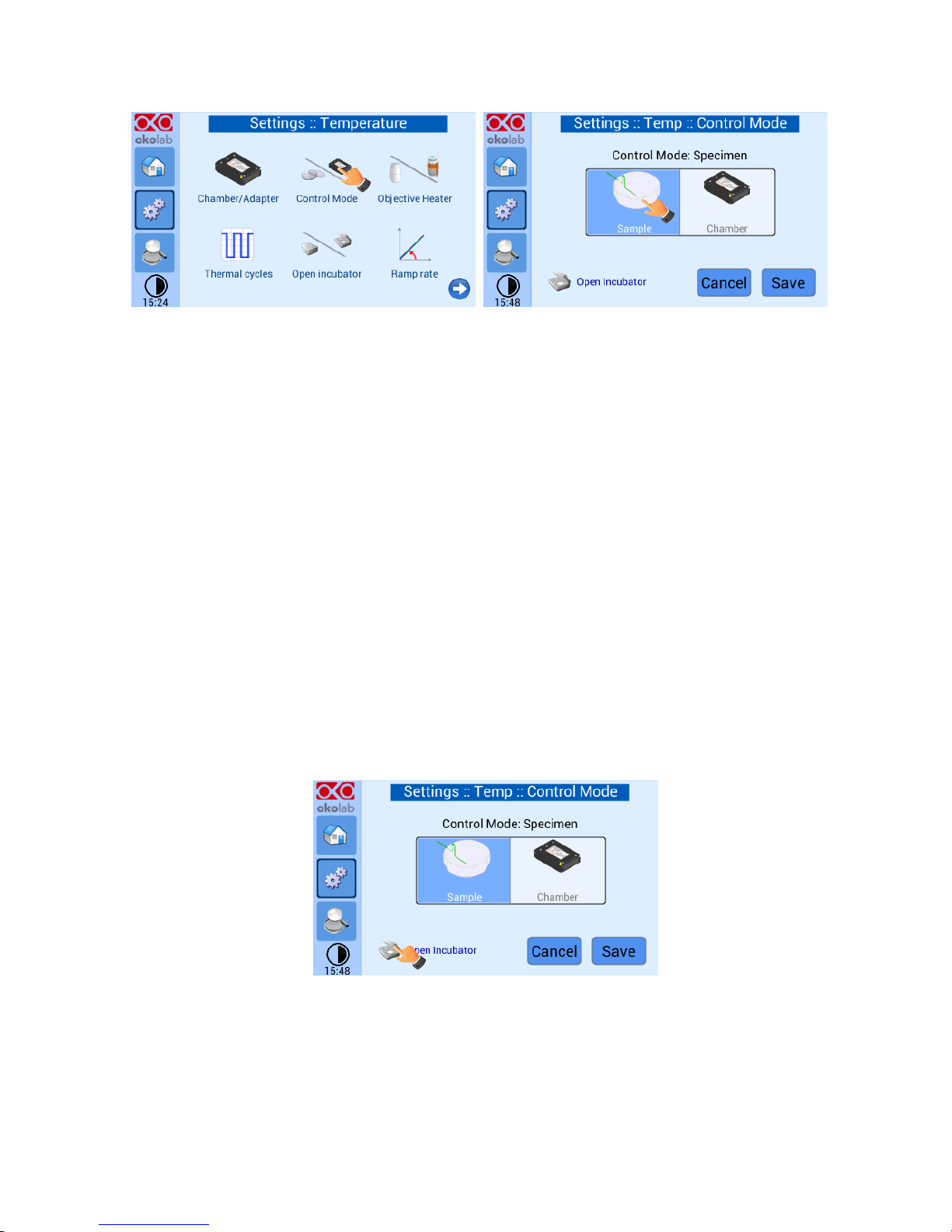
Figure 17 shows how to select the Sample Feedback Mode.
Page 20
20
Figure 17. Sample Mode setting
In this configuration, every time you run an experiment, you must place the Fine Gauge Thermocouple (thin
green wire) into a Petri dish or well adjacent to your sample (from here on this will be referred to as
Reference Well). Fill the Reference Well with distilled water to a level allowing full immersion of the fine
gauge thermocouple (see Figure 49). When possible close the petri with its own plastic lid (or with SENSOR
LID, see Tip in paragraph 7) and place it in the appropriate holder. Using a Reference Well in close proximity
to your Experimental Well provides active Sample Feedback Temperature Control. This ensures that your
sample will be within 0.1°C from the temperature set point regardless the room temperature variations.
Tip ► Advantages of Sample Feedback Control Mode are: 1) direct monitoring and active control of sample
temperature and 2) independence from room temperature variations. The disadvantage is that it requires
manual operation for correct placement of the fine gauge thermocouple in a Reference Well.
The Control Mode page also includes an Open Incubator button (see Figure 18). Press Open Incubator before
opening the lid of the Incubation Chamber (e.g. in order to add culture medium). This places the thermal
controller in stand-by and avoids overheating the sample.
Note ►: this feature is available only when operating in Sample Feedback Mode Control.
Figure 18. Open Incubator
After closing the incubation chamber wait a couple of minutes and press “Incubator Closed”. Now you can
continue your experiment.
Page 21
21
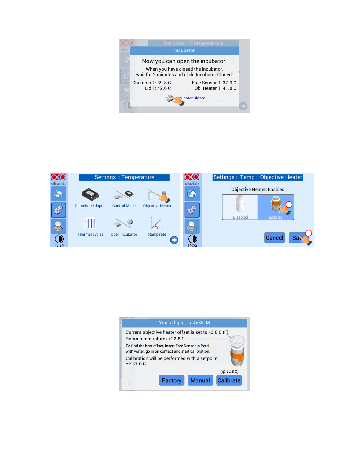
Figure 19. Incubator Closed
6.2.1.3 Objective Heater
Figure 20 shows how to enable/disable the Objective Heater (OBJ COLLAR ####). The Objective Heater is
disabled by default. Read this paragraph only if your system is equipped with Objective Heater (OBJ COLLAR
####).
Figure 20. Objective Heater enabling
Tip ► Before enabling it, make sure it is already installed around your objective, and that it has been
correctly connected to the Temperature Control Unit.
When enabling and saving the Objective Heater the following Screenshot will appear:
Figure 21. Objective Heater Calibration Page
The temperature of the Objective Heater is factory calibrated at room temperature of 23°C, with a 3
degrees offset relative to the sample set-point temperature of 37°C. This offset value is appropriate for a
set point of 37°C. If your set point is different than 37°C the system will automatically apply the correct
1
2
Page 22
22
offset. See Figure 21 above. This means that if the temperature is set at 37°C the Objective Heater is kept
at 40°C in order to maintain the sample at the desired temperature while imaging with an oil immersion
objective. To accept this offset you can press “USE FACTORY” and return to the Homepage. Alternatively
the following options are available:
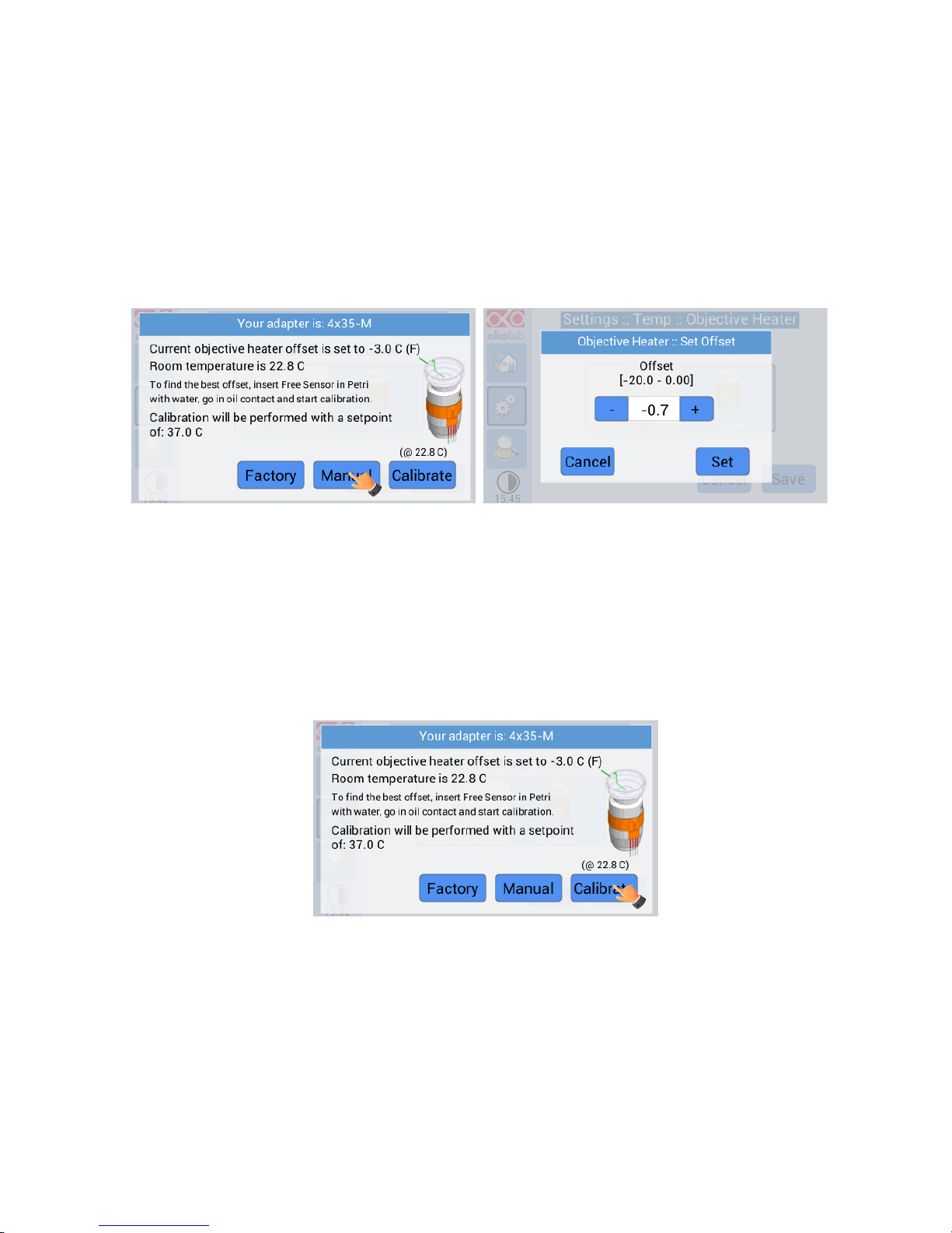
1. MANUAL: Selecting “MANUAL” allows searching for the best offset value manually, step by step. See
Figure 22 below and paragraph 7.2 for instructions on how to manually calibrate the Objective Heater
(OBJ-COLLAR ####).
Figure 22. Objective Heater Manual Offset
2. CALIBRATE: Selecting “CALIBRATE” automatically finds the best offset according to your specific
experimental conditions. For details on this calibration procedure please follow the instructions on
paragraph 7.3. If you are working in “Chamber Feedback Mode”, the starting Self-Calibration
message will be displayed as in paragraph 7.3. If you are working in “Sample Feedback Mode” it will
be displayed.
Figure 23. Objective Heater Self-Calibration Starting Message in Sample Mode
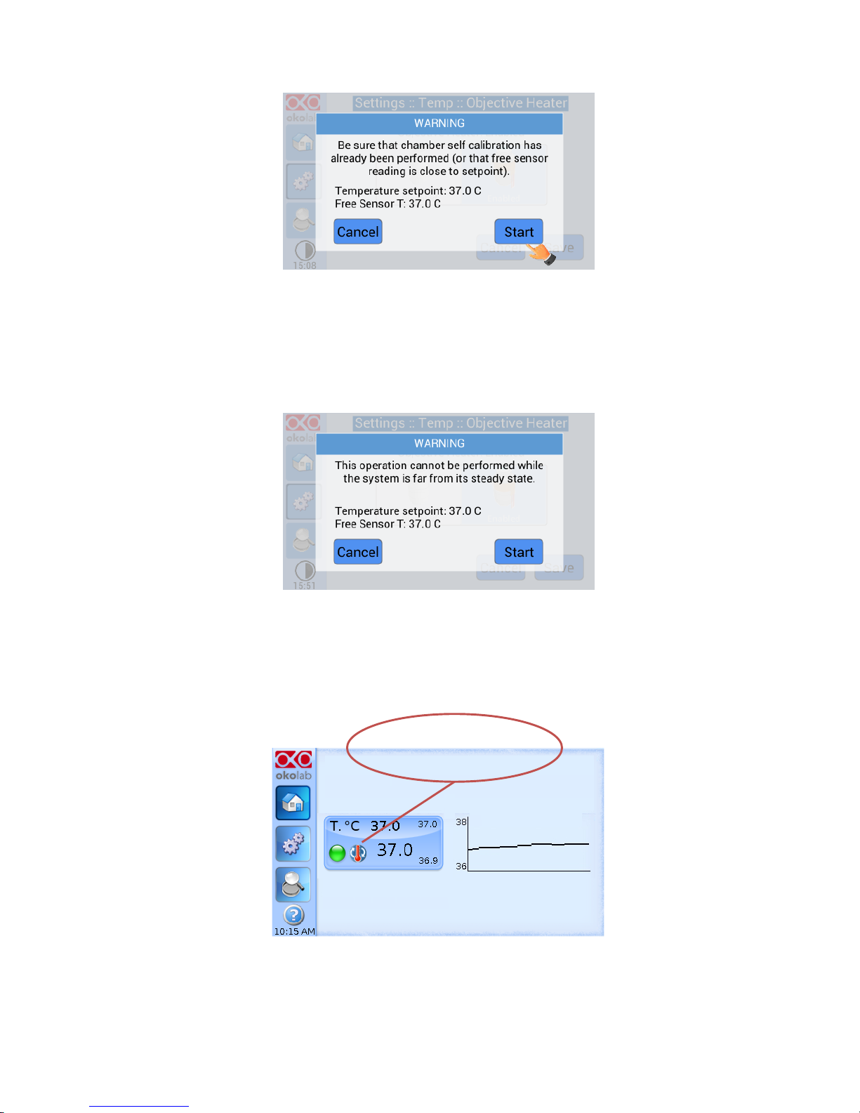
Figure 24 shows the warning message that will appear once you have pressed “Calibrate” if you are working
in Chamber Feedback Mode. This message reminds you that you have to ensure that a Chamber Calibration
has already been completed. Or alternatively, that the factory calibration is appropriate for your laboratory
room temperature (i.e. that, even in Chamber Mode, the sample is close to the Set Point temperature). If
you are unsure it is recommended to re-check the room temperature and decide whether to re-calibrate
the chamber.
Page 23
23
Figure 24. Self-calibration Warning in Chamber Mode
Figure 25 shows the warning message that will appear once you have pressed “Calibrate” if you are working
in Sample Feedback Mode. This message appears only if the Fine Gauge Thermocouple is far from the Set
Point value. If the Fine Gauge Thermocouple is close to the set Point value, the Self-Calibration start will
automatically.
Figure 25. Self-Calibration warning in Sample Mode
The calibration procedure typically takes more than one hour. When the calibration is in process a reminder
icon will appear on the Temperature tab. Once the calibration is completed the reminder icon will
disappear (see Figure 26).
Figure 26. Homepage during Objective Heater Calibration
This symbol indicates
there is a
Self Calibration in
progress
Page 24
24
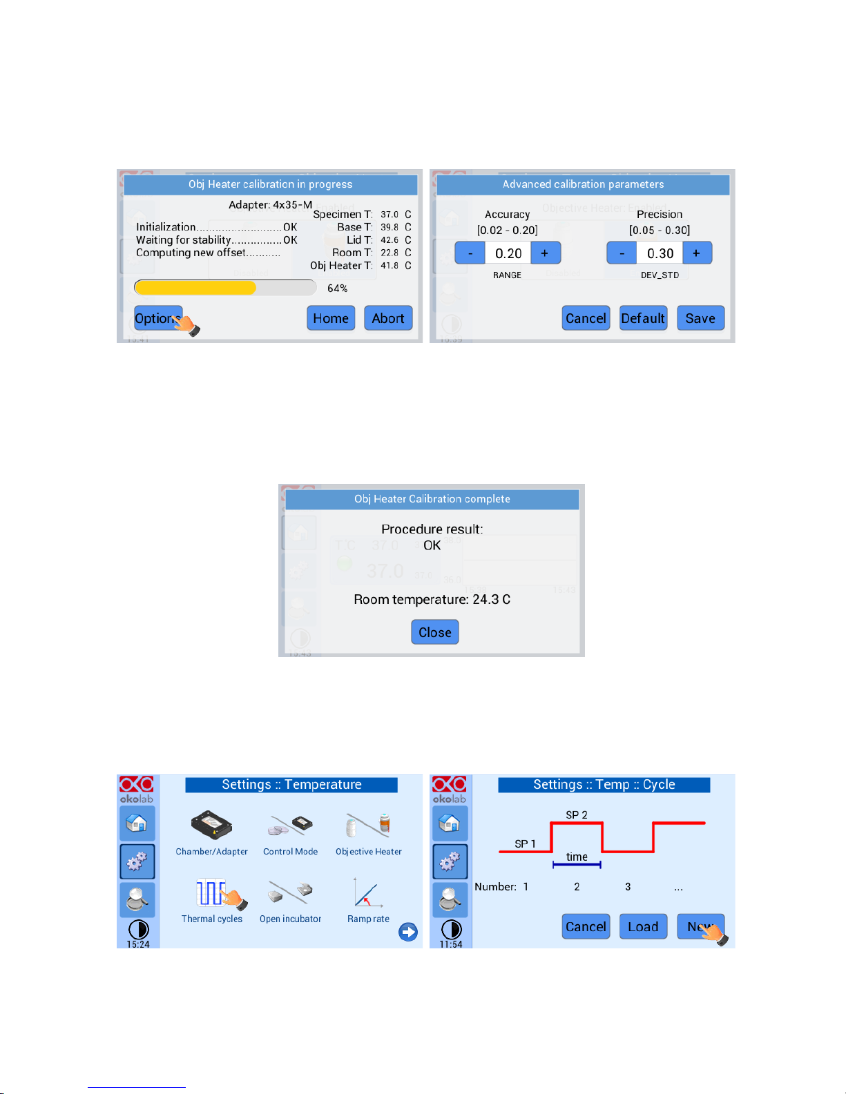
In the Objective Heater Calibration progress window press “Options” to access “Advanced Calibration
Parameters”. In this window you can adjust Accuracy and Standard Deviation, which will be calculated over
10 minutes of readings. This allows setting more stringent parameters to the objective heater calibration.
Figure 27. Objective Heater Self Calibration parameters
Tip ►The higher these values (therefore the less accurate and precise is the calibration), the less time is
taken by the calibration procedure to complete. Use default values to get the most accurate calibration.
Once the calibration procedure is completed, the following message appears.
Figure 28. Objective Heater Self-Calibration end
6.2.1.4 Thermal Cycles
This function allows the incubator to switch between two different temperatures (both temperatures must
be at least 3°C above Room Temperature).
Figure 29. Thermal Cycles Subpage
Page 25
25
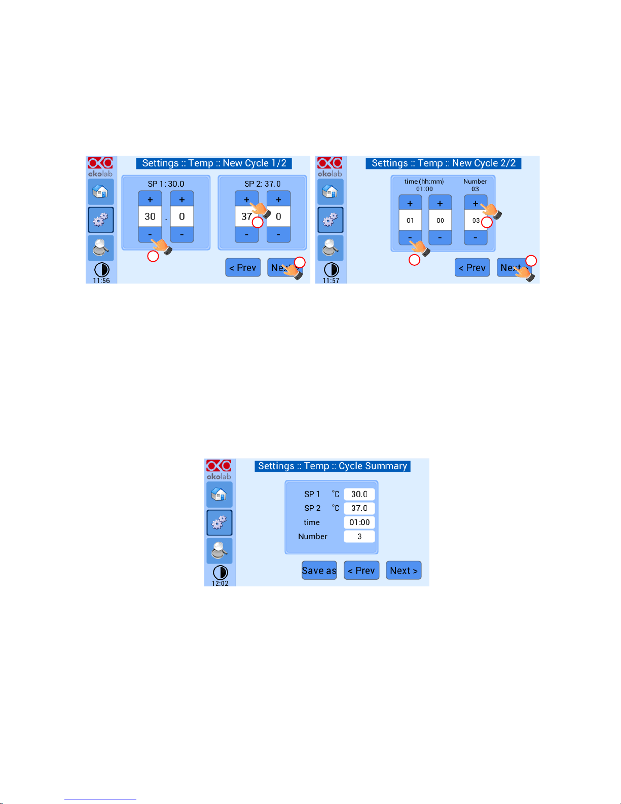
You can decide whether setting a new thermal cycle (“New”) or recalling a previously saved one (“Load”).
To set a new thermal cycle, first choose the two temperatures between which you want to switch (SP1: Set
Point 1 and SP2: Set Point 2). Next, set the duration in hours and minutes you want the system to dwell on
each temperature. Lastly set the number of thermal cycles (“Number”) you want the system to perform
(see Figure 30)
Figure 30. Thermal cycles settings
Tip ► The system switches from a higher to a lower temperature by dissipation; hence it requires some
time (the amount of time required depends on several factors such as control mode, room temperature and
set-points). Please keep this in mind when setting the “time” between the two set points.
Once you have adjusted the settings, a “Cycle Summary” page will be displayed. Press “Save As” if you want
to save the Thermal Cycle program to be recalled for future experiments. You can save up to 4 different
thermal cycle programs. Saving a 5th one will overwrite the first saved one.
Figure 31. Thermal cycle Summary
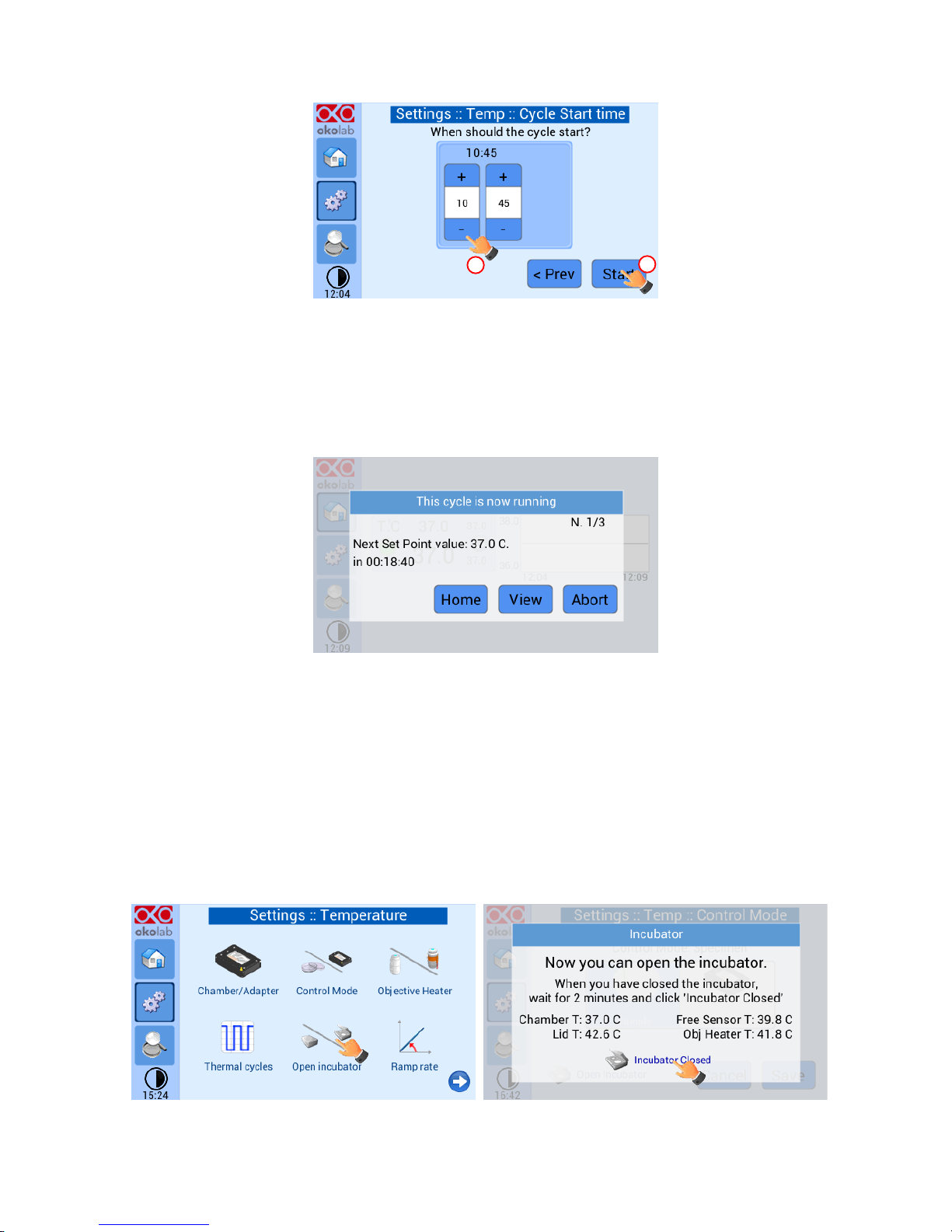
In the last step you can schedule the time you want the thermal cycle to start.
1
3 2 1 2 3
Page 26
26
Figure 32. Cycle Start Time
At set time the cycle will start. A thermal cycling icon will be displayed on the Homepage as a reminder.
Trying to change set points or starting a new thermal cycle while a different one is still running will open
the window in Figure 33. You can press Abort Cycle to modify it or start a new one. Pressing ‘View’ will
open the current thermal cycle settings.
Figure 33. Running Cycle window
6.2.1.5 Open Incubator
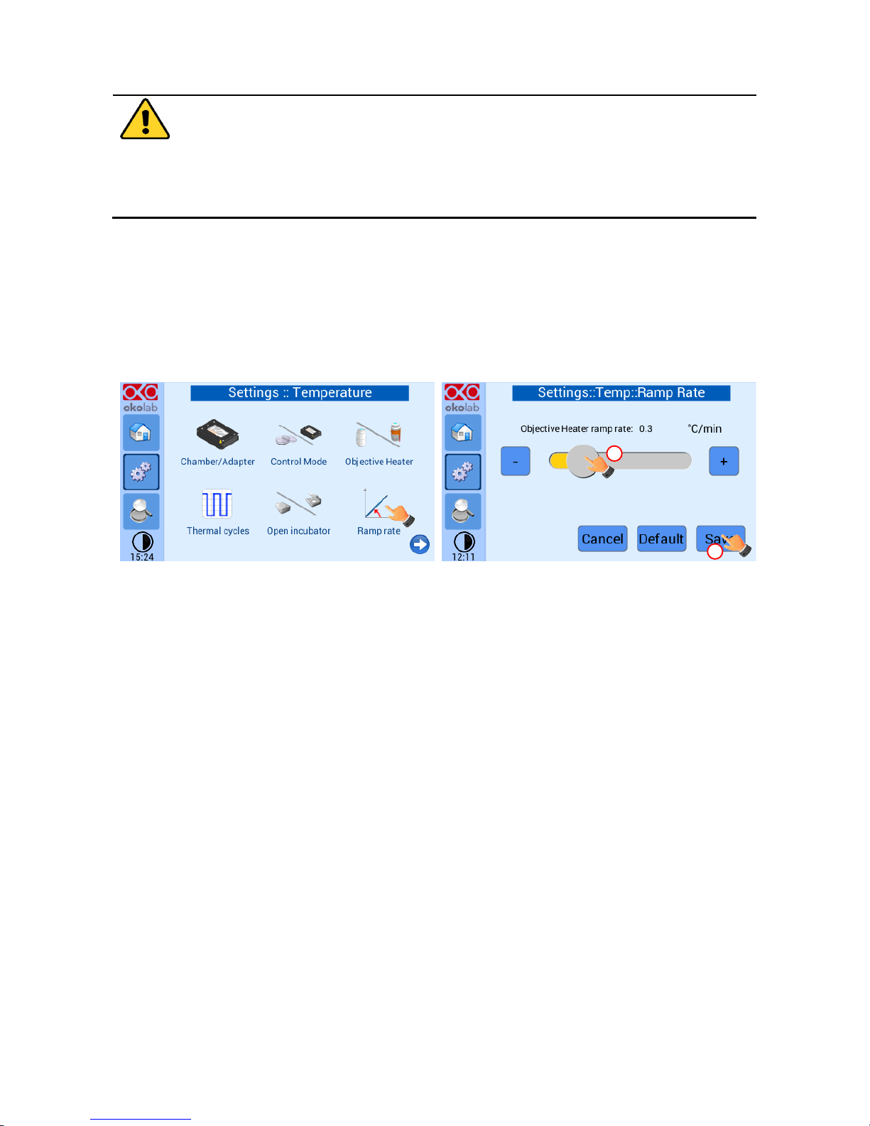
During the normal operation it could be necessary to open the incubator. The picture below shows the
procedure to follow when opening incubator:
1. Press on Open Incubator, before removing the lid. Now you can open the incubator;
2. Once you are done close the chamber and wait for 2 minutes in order to let the environment achieve
steady state; press on Incubator Closed and the temperature controller will resume operating
normally.
Figure 34. Open incubator
1
2
Page 27
27
Opening the incubator can lead to controller instability since both the specimen and the
inside of the chamber are exposed to the external environment. In order to avoid the
problem, UNO CONTROL UNIT has to stay in a holding state until the incubator is closed and
its environment is in a steady state. This can be achieved using the Open Incubator
procedure.
6.2.1.6 Ramp Rate
The Ramp rate is expressed in °C/min and sets how fast the temperature of the objective heater rises. This
means that if you set it at 0.5, the objective heater won't be able to heat up more than 0.5°C in a minute.
We suggest to set the ramp rate at 0.5°C/min in order to avoid eventual cracks inside the objective when
temperature rises too fast.
Press on the ramp rate icon to access its settings, as the picture below shows:
Figure 35. Ramp rate
6.2.1.7 External Sensors
There are two external temperature sensors connected to the Temperature Control Unit. A white thermistor
is to be placed in air to monitor the Room Temperature. A green Fine Gauge Thermocouple, to be placed
into a reference well if running the “Sample Control Mode” or to run Chamber or Objective Heater
calibrations. IMPORTANT: when running the Temperature Control Unit in Sample Feedback Mode the
green Fine Gauge Thermocouple MUST be immersed in liquid in a Reference Well. Failure to do so will
result in overheating of the chamber. When running in “Chamber Feedback Mode” the green Fine Gauge
Thermocouple can be placed in any area of the system to monitor temperature in that area. With this setup
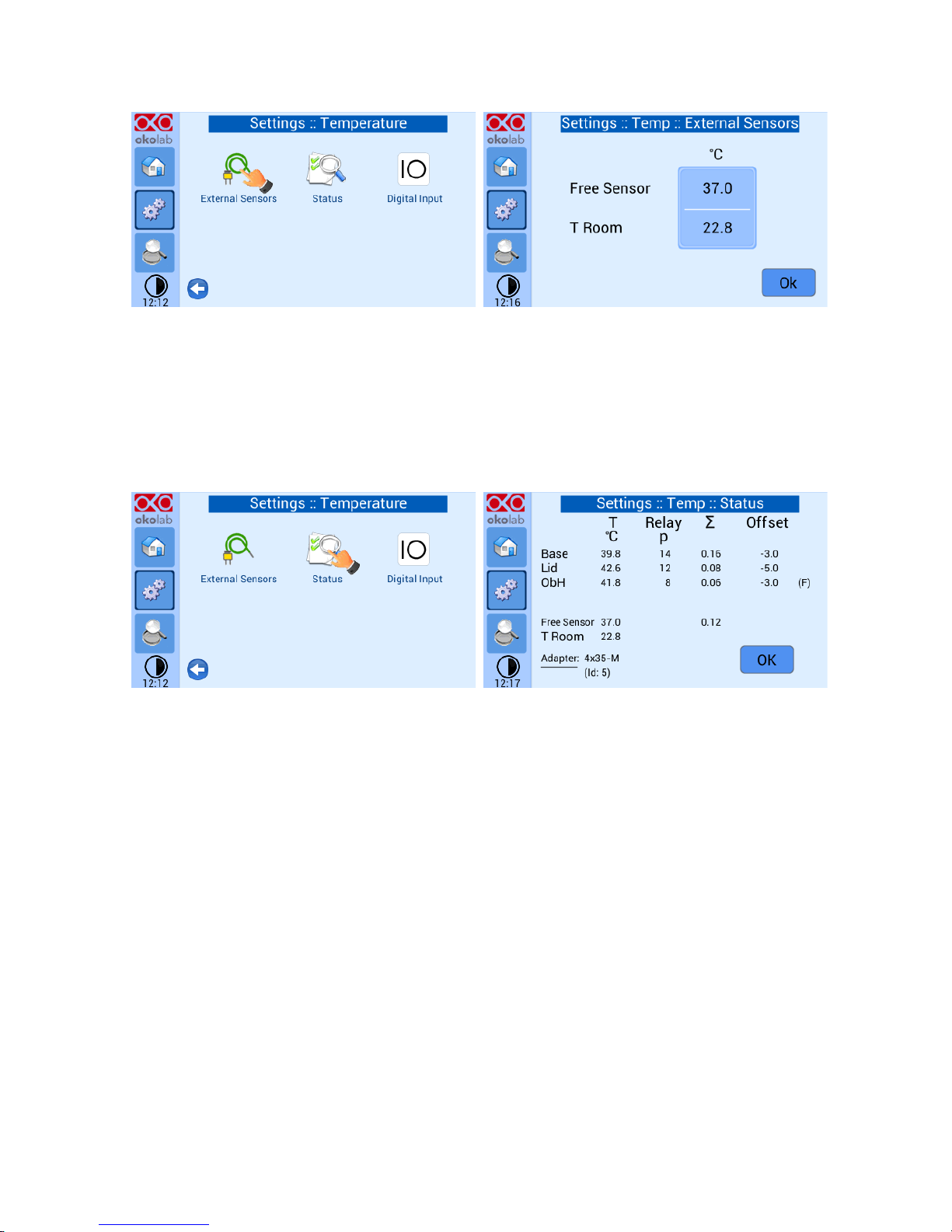
you can monitor both temperatures read by the thermistor (T Room) and by the thermocouple (Free Sensor)
(see Figure 42).
1
2
Page 28
28
Figure 36. External sensors subpage
6.2.1.8 Status
To open the ‘Status’ page press the tab with gears on the left side of the screen. The ‘Settings:
Temperature’ page will open, next select ‘Status’. On this page you can see the status of the Temperature
Control Unit, with a summary of all parameters allowing you to check that all is working properly. You may
have to refer to this window when asking for Okolab technical support.
Figure 37. Status page
6.2.1.9 Digital Input
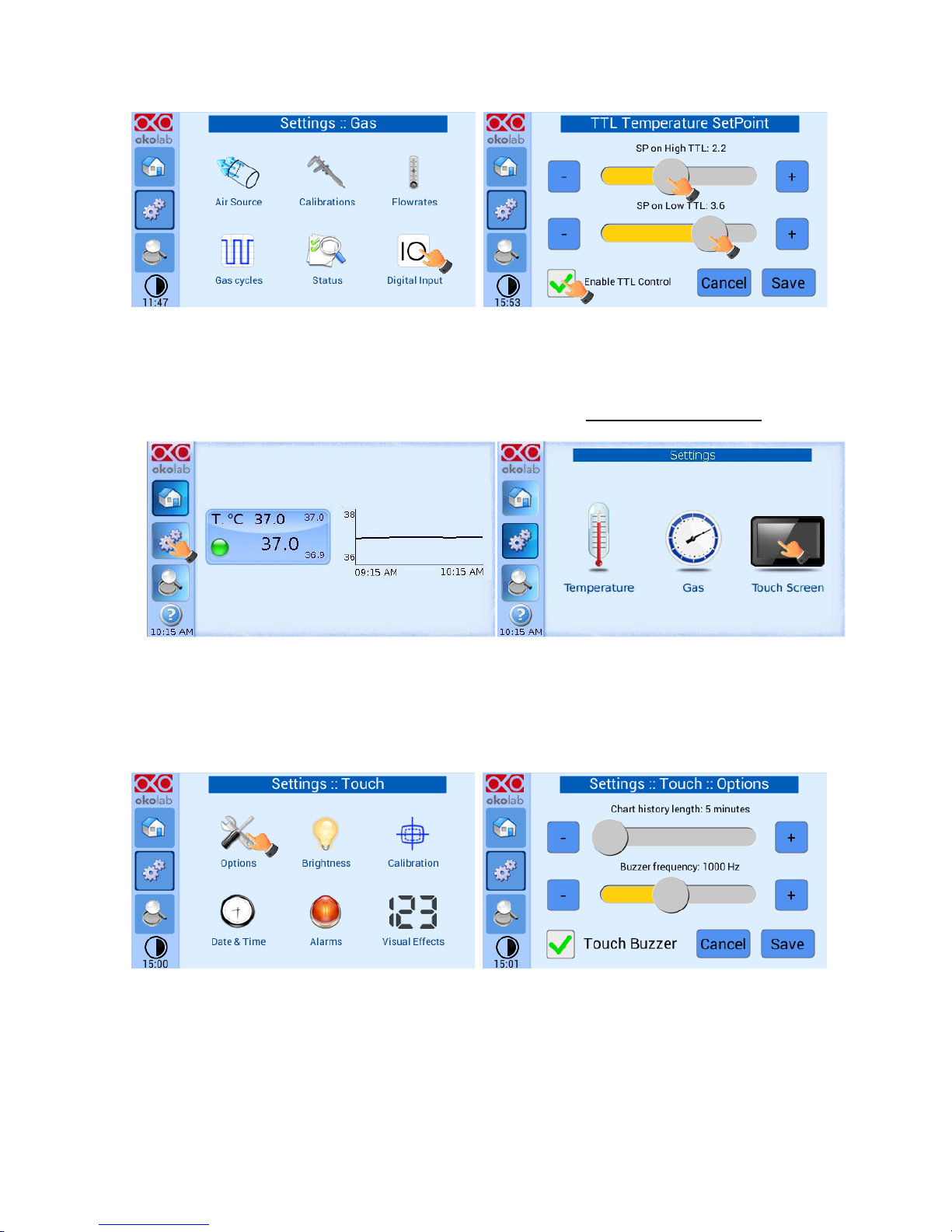
Digital Input feature is available only for TTL ready (optional) controller.
TTL feature allows to change setpoint between two specified values using a TTL signal. The TTL is a digital
input for our Units and has only two values: High and Low. The setpoint values for High TTL value and for
Low TTL value can be set using OKO-TOUCH, via GPIO connector.
When TTL Control is enabled, the user cannot change the setpoint using the dialog in the main page. In this
case, the setpoint value is read by the external TTL signal.
Page 29
29
Figure 38. Digital input
6.2.2 Touch Screen
Touch Screen Settings are adjusted by following the two steps below (look at the touching finger)
Figure 39. Touch screen settings
6.2.2.1 Options
In this window you can set the scale of the X axis (time duration) of the graphs displayed in the main page
and the buzzer sound frequency.
Figure 40. Touch Options
Press and slide your finger along the setting bars or simply click +/- to set desired values, then press “Save”.
Tip ► Recommended value for the chart history length is 60 or 120 minutes.
Page 30
30
6.2.2.2 Brightness
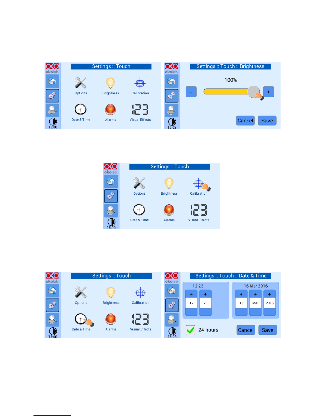
This page allows you to increase/reduce the brightness of the touch screen, scroll the bar or press the +/-
buttons.
Figure 41. How to enter in Alarms page
6.2.2.3 Calibration
When pressing the calibration icon, the procedure for the calibration of the touch screen will start.
Figure 42. Touch screen calibration
6.2.2.4 Date & Time
The first time you turn the system on, it is important to set date and time, use the + and – to set correct
date/time and then press “Save”.
Figure 43. Touch screen settings. Date and Time
Press “Home” (first one on the left menu) to go back to the main page.
Page 31
31
6.2.2.5 Alarms
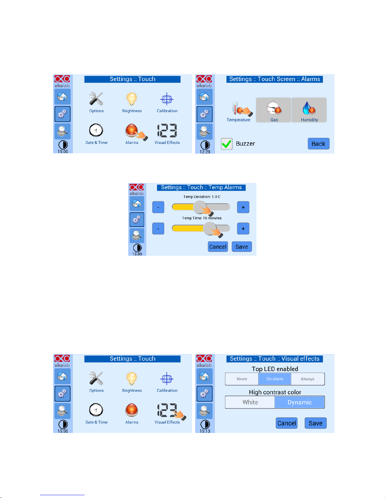
This page allows you to set deviation values (from set-point) beyond which you want the system to trigger
an Alarm.
Figure 44. How to enter in Alarms page
Tip ►Flag “Buzzer” if you want the Alarm to be acoustical as well rather than just being displayed.
Figure 45. How to set the Deviation and Time Alarm
Figure 45. In this example the following settings are displayed (valid only after the system has reached its
stationary state): if Temperature Deviation from set point is 1°C or greater (i.e. if set point temperature is
37°C and the temperature reaches a value equal or less than 36.5°C or equal or more than 37.5°C) for a
period of time equal or longer than 15 minutes (“Temp time“ set in this example) then the system triggers
an Alarm.
6.2.2.6 Visual Effects
To enter the display visual effects menu, press on “Visual Effects” icon
The Top LED settings allows you to when the Top LED should be illuminated: if you select Never, the Top
LED will never illuminate, if you select On Alarm, the Top LED will illuminate only when theH401-T-
Page 32
32
CONTROLLER is in Alarm Status (see paragraph 6.1.1), if you select Always, the Top LED will always
illuminate.
The Glance mode setting defines the color of the Top LED and of the digits displayed in Glance Mode. If you
select White, the Top LED illuminates in white color (according to the criterion selected in Top LED setting)
and the digits displayed in Glance Mode are white. If you select Dynamic the color of the Top LED and the
color of the digits in Glance Mode follow the color coding reported in paragraph 6.1.1.
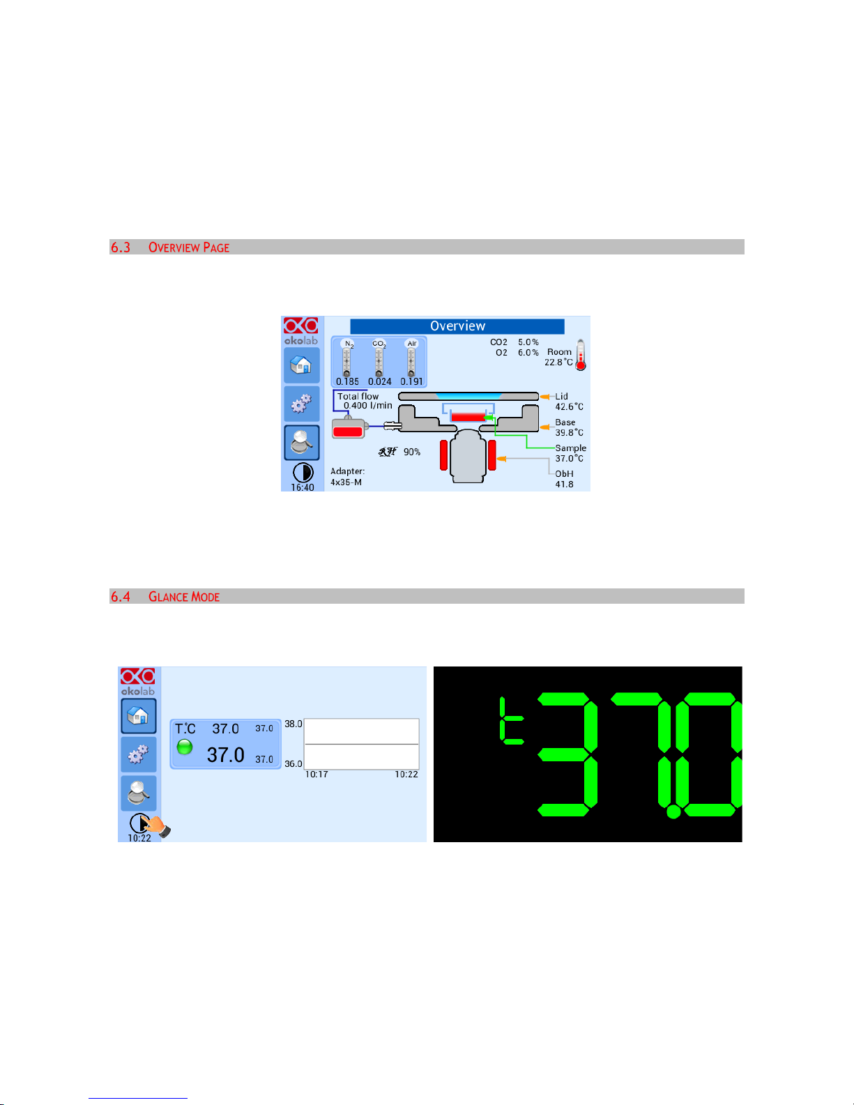
Figure 46 shows an overview of the complete system displaying current values of all controlled parameters.
Similarly to the Status Page you may have to refer to this window when asking for Okolab technical support.
Figure 46.Overview page
Figure 46 shows the Overview page when your system is equipped with the Objective Heater (OBJ COLLAR
####), CO2-O2-UNIT [0-10; 1-18] and HM-ACTIVE.
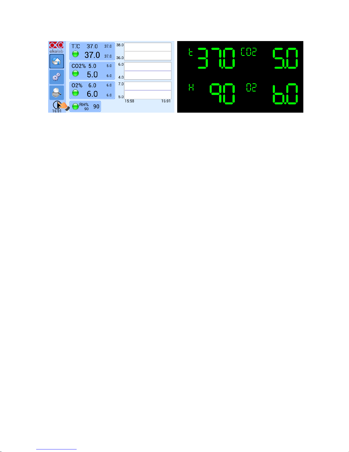
Pressing on ‘Glance Mode’ you can change the data visualization format on the Homepage that turns into a
brief information about the state of the controller and the attached ones.
Figure 47. Glance Mode with temperature controller only
Page 33
33
Figure 48. Glance Mode with temperature controller, CO2-O2 gas controller and active humidity controller
Page 34
34
7 CALIBRATIONS
Carefully read the instructions given in this paragraph and before starting the Chamber
Calibration.
Note ► It is important to monitor the room temperature during the calibration, as well as reducing air
drafts and forced convection. If possible divert any draft coming from the air conditioning system in the
room, from the incubation system.
The goal of this procedure is to automatically adjust the temperature offset of the Base and Lid of the
incubation chamber hence maintaining the sample at the desired temperature (e.g. 37°C) during imaging.
Before starting the Chamber Self-Calibration:
1. Plug the green Fine Gauge Thermocouple in the port labeled “Reference Temperature” located in
the rear panel of the Temperature Control Unit, as illustrated in Figure 2.
2. Insert the Fine Gauge Thermocouple into the chamber by threading the wire through one of the
screw holes on the chamber riser.
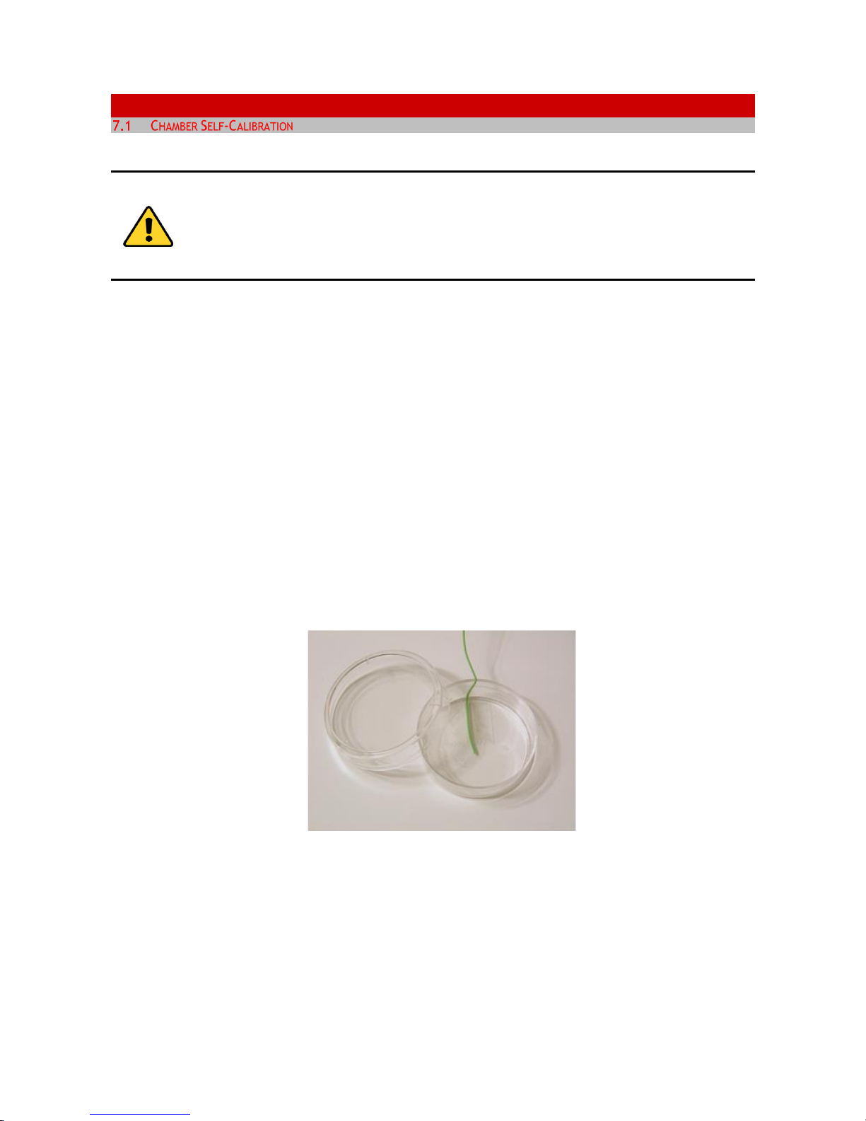
3. Secure the end of the Fine Gauge Thermocouple to the bottom of a 35mm or similar Petri dish using
some tape making sure to avoid covering the head of the probe (see Figure 49).
Figure 49. Free Sensor attached on the internal base of the Petri Dish
4. Fill the Petri dish with distilled water to a level sufficient to fully immerse the Fine Gauge
Thermocouple. This is a Reference Well simulating experimental conditions. Place the lid on the
Petri dish, and insert the dish in the incubation chamber. You can also use SENSOR LID-# to close the
dish (see the “Tip” below).
Page 35
35
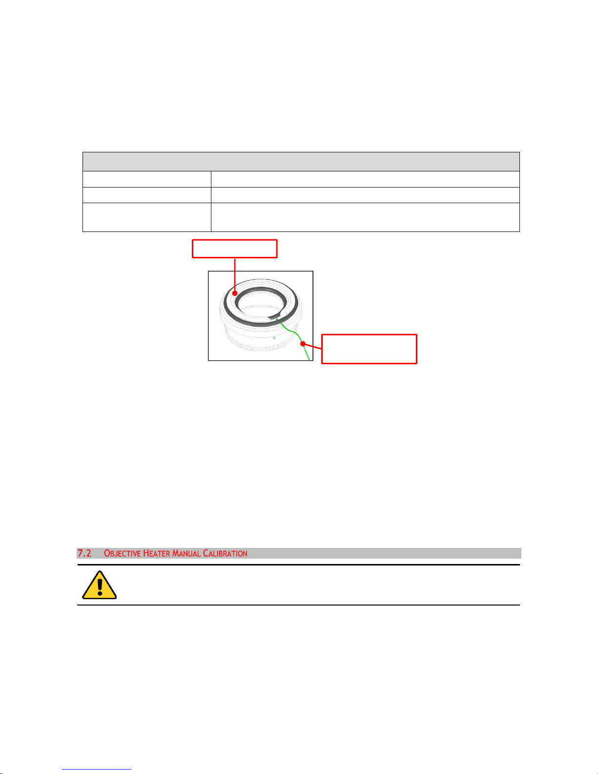
Tip ► It is recommended using an Okolab SENSOR LID (available for purchase) to secure the Fine Gauge
Thermocouple in place in the Reference Well during calibration or operation in Sample Feedback Mode (see
Figure 50).
Sensor lids are available for the following: 35 mm, 60 mm Petri-dish, chamber slide and chambered cover
glass. Sensor Lids are ordered separately using the codes in following table.
SENSOR LID CODES
SENSOR LID-35
Temperature sensor lid. To be used in specimen feedback in a 35 mm Petri Dish
SENSOR LID-60
Temperature sensor lid. To be used in specimen feedback in a 60 mm Petri Dish
SENSOR LID-GS
Temperature sensor lid. To be used in specimen feedback in chamber slides and
chambered cover glass
Figure 50. SENSOR LID-35. For 35 mm Petri-dish
5. Go in Control Mode page as shown in Figure 13 and enable “Chamber Mode”, the page shown in
Figure 14 will open.
6. Next press “Calibrate” to start the Self-Calibration program.
7. Self-Calibration may take 1-2 hours to complete, during this time the dialog shown in Figure 15 will
be displayed. Once the Self-Calibration procedure is complete the window shown in Figure 16 will
be displayed.
8. You can remove the Fine Gauge Thermocouple from the Reference Well petri-dish inside the
incubating chamber. When running in Chamber Feedback Mode the system will use the parameters
from the calibration at your Room Temperature.
Carefully read the instructions given in this paragraph and in paragraph 6.2.1.3 before
starting the Objective Heater Manual Calibration.
The goal of this procedure is to adjust the controlled Objective Heater temperature manually, varying its
offset; while maintaining the sample at the desired temperature (e.g. 37.0 °C) once the oil immersion
objective is in contact with the bottom of the well. This can be achieved measuring the sample temperature
with the Fine Gauge Thermocouple during steady state and estimating the offset values, as follows:
1. Plug the green Fine Gauge Thermocouple in the port labeled “Reference Temperature” located in
the rear panel of the Temperature Control Unit, as illustrated in Figure 2.
SENSOR LID
Fine Gauge
Thermocouple
Page 36

36
2. Insert the Fine Gauge Thermocouple into the chamber by threading the wire through one of the
screw holes on the chamber riser.
3. Secure the end of the Fine Gauge Thermocouple to the bottom of Petri dish using some tape making
sure to avoid covering the head of the probe (see Figure 49).
4. Fill the Petri dish with distilled water to a level sufficient to fully immerse the Fine Gauge
Thermocouple. This is a Reference Well simulating experimental conditions. Place the lid on the
Petri dish, and insert it in the incubation chamber. You can also use SENSOR LID-# to close the dish
(see the “Tip” in paragraph 7).
Note ► Please, monitor the room temperature during the calibration and reduce air drafts and forced
convection. If possible divert any draft coming from the air conditioning system in the room, from the
incubation system.
5. Wait until the system reaches the steady state (temperature indicator status is green) then approach
the oil immersion objective to the bottom of the Petri dish. The Fine Gauge Thermocouple will detect
a decrease in temperature because of the contact with the cold lens. You can see the Fine Gauge
Thermocouple temperature decreasing in the Status page (see paragraph Figure 37) whether you are
working in “Chamber Feedback Mode” or in “Sample Feedback Mode
If you are working in “Chamber Feedback Mode”, verify that the Chamber Calibration has
already been completed. Or alternatively, that the factory calibration is appropriate for your
laboratory room temperature (i.e. that, even in Chamber Mode, the sample is close to the
Set Point temperature). If you are unsure it is recommended to re-check the room
temperature and decide whether to re-calibrate the chamber (see 6.2.1.2) and then the
Objective Heater.
6. When the Fine Gauge Thermocouple reads a stable temperature open the “Objective Heater” page
as shown in Figure 20 and select “Use Manual” (see Figure 22). Next click on “+” or “-” on the
“Offset” tab (see Figure 22) to adjust the Objective Heater offset value. Okolab recommends starting
with an offset value corresponding to the difference between the set point temperature and the
actual temperature measured by the Fine Gauge Thermocouple. Press “Set” and wait until the
temperature measured by the Fine Gauge Thermocouple is stable. If the temperature measured by
the Fine Gauge Thermocouple is now close to the set point, then the Manual Calibration is complete.
If the temperature measured by the Fine Gauge Thermocouple is far from the set point, repeat the
steps above until the temperature measured by the Fine Gauge Thermocouple reaches the set point
temperature
Page 37

37
Before starting the Objective Heater Self-Calibration carefully read the instructions given in
this paragraph and in paragraph 6.2.1.3.
The goal of the Self-Calibration procedure is to adjust the Objective Heater temperature by automatically
varying its offset; while maintaining the sample at the desired temperature (e.g. 37.0 °C) once the oil
immersion objective is in contact with the bottom of the well. Before starting the Objective Heater Self-
Calibration:
1. Plug the green Fine Gauge Thermocouple in the port labeled “Reference Temperature” located in
the rear panel of the Temperature Control Unit, as illustrated in Figure 2.
2. Insert the Fine Gauge Thermocouple into the chamber by threading the wire through one of the
screw holes on the chamber riser.
3. Secure the end of the Fine Gauge Thermocouple to the bottom of Petri dish using some tape making
sure to avoid covering the head of the probe (see Figure 49).
4. Fill the Petri dish with distilled water to a level sufficient to fully immerse the Fine Gauge
Thermocouple. This is a Reference Well simulating experimental conditions. Place the lid on the
Petri dish, and insert it in the incubation chamber. You can also use SENSOR LID-# to close the dish
(see the “Tip” in paragraph 7).
Note ► Please, monitor the room temperature during the calibration and reduce air drafts and forced
convection. If possible divert any draft coming from the air conditioning system in the room, from the
incubation system.
5. Wait for until the system reaches the steady state (temperature indicator turns green) and then:
A. Chamber Feedback Mode:
Enable the Objective Heater as shown in Figure 20. Follow the instructions on the message: first you
have to bring your immersion lens in contact with the Petri dish, next press “CALIBRATE”. Following
this sequence of instructions REQUIRED to control the Objective Heater only, without interfering
with the incubation chamber.
Once you have pressed “Calibrate”, the dialog shown in Figure 24 will open. If the Fine Gauge
Thermocouple is close to the Set Point Value, press “Start”, otherwise you have to calibrate the
Chamber Incubator first and then can calibrate the Objective Heater.
Make sure that Chamber Calibration is completed. If the Fine Gauge Thermocouple measures
a temperature far from the Set point Value pressing, “Start” will still launch the Self-
Calibration procedure. This is NOT advisable because the procedure will raise the offset
value of the objective heater.
B. Sample Feedback Mode:
Page 38

38
Enable the Objective Heater as shown in Figure 20, the window in Figure 23 will open. Follow the
instructions on the message: first press “CALIBRATE”, next bring the immersion lens in contact with the
petri-dish. Following this sequence of instructions is REQUIRED to place the Fine Gauge
Thermocouple in standby and act on the Objective Heater only.
The calibration procedure typically takes longer than one hour. While calibrating an icon will appear on the
Homepage Temperature tab (see Figure 26) to remind you of the ongoing calibration. Once the calibration
is completed the icon will no longer appear.
In the Objective Heater Calibration progress window press “Options” to access “Advanced Calibration
Parameters” (see Figure 27). In this window you can adjust Accuracy and Standard Deviation, which will be
calculated over 10 minutes or readings. This allows setting more stringent parameters to the objective
heater calibration.
Tip ►The higher are these values (therefore the less accurate and precise is the calibration), the less time
is taken by the calibration procedure to complete. Use default values to get the most accurate calibration.
When the calibration procedure is completed, the message shown in Figure 28 will appear.
Page 39
39
8 MAINTENANCE
To maintain proper Temperature Control Unit operation over time:
Use a polishing cloth or dry cloth to wipe off dust and dirt.
Never use thinners, benzene, solvents on or near the devices, since these could corrode their surfaces.
To polish the Stage Incubator and the Humidifying Module, if it is present, you can use distilled water
or alcohol
Verify the status of all cables and if some cable is damaged, contact Okolab to receive assistance
Before cleaning the unit, pull out the mains plug.
Water must not be entered in the system.
Page 40
40
9 SUPPORT
In order to send directly an email to the Okolab staff, you can use the QR codes shown in the following
images:
• For commercial info:
Figure 51. QR code for commercial info contact
• For technical info:
Figure 52.QR code for technical info contact
Please, do not hesitate to contact Okolab if you need any further commercial information or technical
support.
Please, check Okolab web site www.oko-lab.com for news, events, new products and general FAQs.
Phone +39 081 806 2624
Fax: +39 081 876 4410
Mobile: +39 348 9680717
Phone +39 081 806 3470
Mobile: +39 348 9680718
Okolab S.r.l.
Via A. Olivetti, 1 - 80078 Pozzuoli, NA
Italy
In case you requested on line support and/or web conference assistance for system assembling and
experiment support, you received a web cam. Please follow these guidelines to receive optimum service.
• Webcam installation (instruction and Cdrom included)
• Latest Skype
®
software installed (www.skype.com)
• Register yourself on www.skype.com to have an account (Skype_ID)
• Set the audio and video and test them using Skype.
Page 41

41
assistance.
Page 42
42
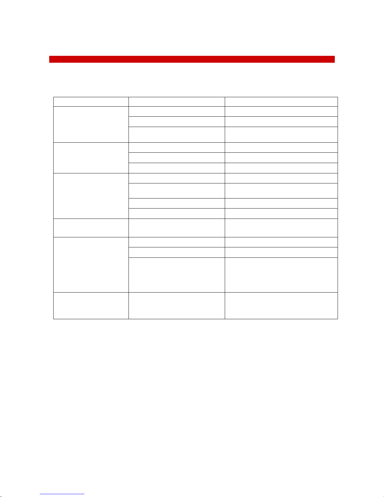
10 TROUBLESHOOTING
Incorrect operations are often mistaken for malfunction. If you think that there is something wrong with a
component, see the troubleshooting scheme below. If the problem persists even after troubleshooting as
described below, please ask for Okolab support
Symptom
Probable cause
Remedy
Device off
Supply cable disconnected
Properly connect the cable
Supply cable damaged
Substitute the cable
Blown fuse
Replace the fuse (see Technical Specifications)
No temperature displayed or
“nan"
Thermocouple cable disconnected
Properly connect the cable
Thermocouple cable damaged
Contact Okolab to receive assistance
Embedded sensors damaged
Contact Okolab to receive assistance
Chamber Base and Lid cold
Low set point value
Change the set point
Heater 1/2 and/or cable disconnected
Connect the cable
Heater 1/2 and/or cable damaged
Contact Okolab to receive assistance
Heating elements damaged
Contact Okolab to receive assistance
Alarm rings (for specimen
temperature feedback)
Chamber Base at high temperature (for
specimen temperature feedback)
Quickly shoot down the control unit and properly
set the system. Please, check below
Chamber Base at high
temperature (for specimen
temperature feedback)
Control thermocouples connection
Check the connection scheme
Damaged thermocouple
Ask Okolab for replacement
Sensor out of the reference well or
chamber open
Make sure that the thermocouple is correctly
positioned in the reference well and that the
incubating chamber is closed (if working in
“Specimen Control Mode)
I check the previous
troubleshooting but I cannot
solve the problem
Contact Okolab to receive assistance
Page 43
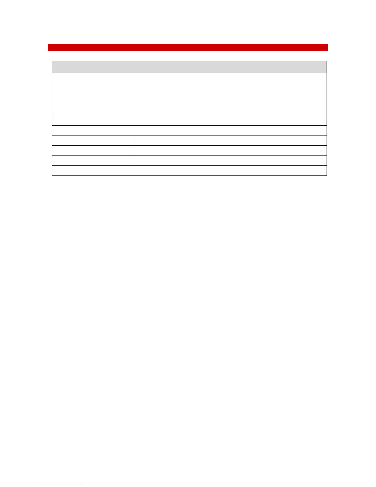
11 TECHNICAL SPECIFICATIONS
H301-T-UNIT-BL-PLUS – Technical Specifications
Temperature
Chamber Temperature Range: 25-60°C
Sample Temperature range: 3°C above ambient temperature to 60°C
Step size: 0.1°C
Accuracy:0.1°C in Sample Mode, 0.3°C in Chamber Mode if room temperature remains
within ± 1°C
Regime temperature time
about 30 min
Operating Temperature
0°C ~ +55°C
Storage Temperature
-5°C ~ +60°C
Operating Humidity
0-70%
Power Consumption
24 V DC 100 W max
Weight
1.6 Kg
Page 44

44
12 FIGURE LIST
Figure 1: Control Unit Rear Panel Overview .......................................................................................... 10
Figure 2. H301-T-BL-PLUS. Standard Connection .................................................................................... 11
Figure 3.Objective Heater (OBJ-COLLAR ####) Assembly .......................................................................... 12
Figure 4. OBJ-COLLAR Connection (Optional) ........................................................................................ 12
Figure 5. OKO-TOUCH Connection ...................................................................................................... 13
Figure 6. CO2-O2 UNIT-BL [0-10; 1-18] and H301-T-UNIT-BL-PLUS ............................................................... 14
Figure 7. Homepage of the Control Unit Touch Screen Display.................................................................... 15
Figure 8. How to change the Temperature set point ................................................................................ 16
Figure 9. Temperature settings ......................................................................................................... 16
Figure 10. Chamber & Adapter change ................................................................................................ 17
Figure 11 Chamber & Adapter settings ................................................................................................. 17
Figure 12. Chamber and adapters saving .............................................................................................. 17
Figure 13. Chamber Mode Setting ....................................................................................................... 18
Figure 14. Chamber calibration start ................................................................................................... 18
Figure 15. Chamber calibration progress .............................................................................................. 19
Figure 16. Chamber Calibration result ................................................................................................. 19
Figure 17. Sample Mode setting ......................................................................................................... 20
Figure 18. Open Incubator................................................................................................................ 20
Figure 19. Incubator Closed .............................................................................................................. 21
Figure 20. Objective Heater enabling .................................................................................................. 21
Figure 21. Objective Heater Calibration Page ........................................................................................ 21
Figure 22. Objective Heater Manual Offset ........................................................................................... 22
Figure 23. Objective Heater Self-Calibration Starting Message in Sample Mode ............................................... 22
Figure 24. Self-calibration Warning in Chamber Mode .............................................................................. 23
Figure 25. Self-Calibration warning in Sample Mode ................................................................................ 23
Figure 26. Homepage during Objective Heater Calibration ........................................................................ 23
Figure 27. Objective Heater Self Calibration parameters .......................................................................... 24
Figure 28. Objective Heater Self-Calibration end .................................................................................... 24
Figure 29. Thermal Cycles Subpage .................................................................................................... 24
Figure 30. Thermal cycles settings ..................................................................................................... 25
Figure 31. Thermal cycle Summary ..................................................................................................... 25
Figure 32. Cycle Start Time .............................................................................................................. 26
Figure 33. Running Cycle window ....................................................................................................... 26
Figure 34. Open incubator................................................................................................................ 26
Figure 35. Ramp rate ...................................................................................................................... 27
Figure 36. External sensors subpage.................................................................................................... 28
Figure 37. Status page .................................................................................................................... 28
Figure 38. Digital input ................................................................................................................... 29
Figure 39. Touch screen settings ........................................................................................................ 29
Figure 40. Touch Options ................................................................................................................. 29
Figure 41. How to enter in Alarms page ............................................................................................... 30
Figure 42. Touch screen calibration .................................................................................................... 30
Figure 43. Touch screen settings. Date and Time .................................................................................... 30
Figure 44. How to enter in Alarms page ............................................................................................... 31
Figure 45. How to set the Deviation and Time Alarm ............................................................................... 31
Figure 46.Overview page ................................................................................................................. 32
Figure 47. Glance Mode with temperature controller only ......................................................................... 32
Figure 48. Glance Mode with temperature controller, CO2-O2 gas controller and active humidity controller ........... 33
Figure 49. Free Sensor attached on the internal base of the Petri Dish ......................................................... 34
Figure 50. SENSOR LID-35. For 35 mm Petri-dish ..................................................................................... 35
Figure 51. QR code for commercial info contact ..................................................................................... 40
Figure 52.QR code for technical info contact ......................................................................................... 40
Page 45
45
WARRANTY
Okolab S.r.l. warrants its products to be free of defects in materials and workmanship for a period of one
year starting from invoice date. If the unit malfunctions, it must be returned to the factory for evaluation.
If the equipment has to be returned to the factory, please ensure that is carefully and properly packed.
Okolab S.r.l. accepts no responsibility for damage due to unsatisfactory packing.
Upon examination of Okolab S.r.l., if the unit is found to be defective, it will be repaired or replaced at no
charge. This warranty does not apply to defects resulting from any actions of the purchaser. Okolab S.r.l.
neither assumes responsibility for any omissions or errors nor assumes liability for any damages that result
from any action of the purchaser that discord from instructions listed in the operation manual. This warranty
does not cover or involve any other equipment that may be used along with the Okolab System (i.e. mini-
incubators, any gas tank, etc.), whose usage should be considered independent and performed according to
their own operational instructions.
Okolab S.r.l. warrants only the parts manufactured by it will as specified and free of defects. Okolab S.r.l.
makes no other warranties or representations of any kind whatsoever, express or implied, except that of
title, and all implied warranties including any warranty of merchantability and fitness for a particular
purpose are hereby disclaimed. LIMITATION OF LIABILITY: the total liability of Okolab S.r.l. shall not exceed
the purchase price of the component upon which liability is based. In NO event shall Okolab S.r.l. be liable
for consequential, incidental or special damages.
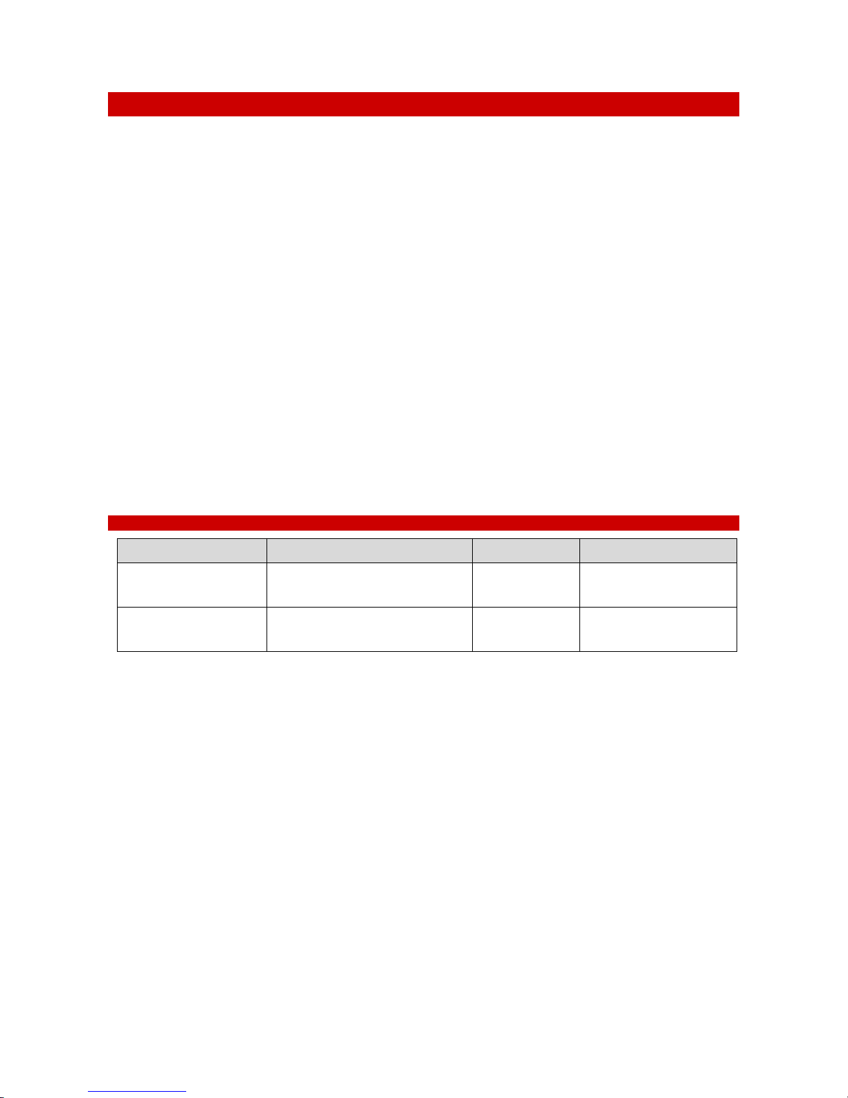
13 REVISION TABLE
Revision Number
Additions or changes
Date
Editor
01
Edited
March 2017
Francesco Marino
02
Revision
March 2017
Francesco Marino
Marino Simeone
IST: 1199
SV: 4.1.9.3019
 Loading...