

OperatingManual
PELLETRONIC
TOUCH
TOUCHV2.00
ENGLISH
Europe’sspecialistinpelletheating
E1389EN2.0

Title:
OperatingmanualPelletronicTouch
Articlenumber:E1389EN2.0
Version:2.0
Versionvalidfrom:05/2013
Approved:
HumbergerStephan
Author:
ÖkoFENForschungs-undEntwicklungsgesmbH
Technicaleditorialdepartment
Gewerbepark1
A-4133Niederkappel
AUSTRIA
Tel.:0043(0)7286/7450
Fax:0043(0)7286/7450/10
oekofen@pelletsheizung.at
www.oekofen.com
©byÖkoFENForschungs-undEntwicklungsgesmbH
Subjecttomodications

Contents
1DearCustomer.................................................................................................................................................5
2Useonlyforthepurposeintended...................................................................................................................6
3Typesofsafetywarningsign............................................................................................................................7
4Pelletronicheatingcontrollerandoperatingdevicewithtouchscreen............................................................8
4.1OperatingDevicewithT ouchscreen.................................................................................................................8
4.2Openingwindow............................................................................................................................................8
4.3Chimneysweep...............................................................................................................................................9
4.4Usercontrolsandtheirfunction..................................................................................................................10
4.5MainMenu....................................................................................................................................................12
5Mode...............................................................................................................................................................13
6MeasuringValues...........................................................................................................................................14
7HeatingCircuit................................................................................................................................................16
7.1MeasuringvaluesHeatingcircuit....................................................................................................................17
7.2TimeprogrammeHeatingcircuit.....................................................................................................................17
7.3Party.............................................................................................................................................................19
7.4Vacation........................................................................................................................................................19
7.5HeatingcurveandHeatinglimits.....................................................................................................................20
7.6Screedprogramme........................................................................................................................................24
8Domestichotwater(DHW).............................................................................................................................25
8.1MeasuringvaluesDomestichotwater.............................................................................................................26
8.2TimeprogrammeDHW..................................................................................................................................26
9DHWReturnpump..........................................................................................................................................27
9.1MeasuringvaluesDHWReturnpump.............................................................................................................27
9.2TimeprogrammeDHWreturnpump...............................................................................................................28
10Solar.............................................................................................................................................................29
10.1MeasuringvaluesSolar................................................................................................................................29
10.2Solarcircuit.................................................................................................................................................30
10.3Yield-SolarEnergy....................................................................................................................................31
11Pellematic.....................................................................................................................................................32
11.1Permanentoperation....................................................................................................................................32
11.2MeasuringvaluesPellematic.........................................................................................................................33
11.3FullPower...................................................................................................................................................34
11.4De-ashingsystem........................................................................................................................................34
11.5FreshWaterModule.....................................................................................................................................35
11.6BoilerCleaning............................................................................................................................................35
11.7SuctionSystem............................................................................................................................................36
11.8Leveldetectionsystem.................................................................................................................................37
12HeatMainPump............................................................................................................................................38
13General.........................................................................................................................................................39
13.1Favorite1and2...........................................................................................................................................39
13.2LocalSettings..............................................................................................................................................40
13.3Malfunction..................................................................................................................................................41
13.4Information..................................................................................................................................................41
14Software.......................................................................................................................................................42
15CodeInput....................................................................................................................................................43
16Startup.........................................................................................................................................................44
17Descriptionoftheheatingcontrollermodule...............................................................................................45
17.1Settingtheaddressattheheatingcontroller..................................................................................................46
17.2Settingtheaddressattheburnercontroller....................................................................................................47
17.3SettingtheaddressattheboilercontrollerCMP.............................................................................................48
17.4Assemblyordisassemblyofthepowersupply...............................................................................................49
17.5Assemblyanddisassemblyoftheheatingcontrollerboard.............................................................................50
18DescriptionoftheOperatingdevicemodule................................................................................................51
18.1ReplacingaTouchoperatingdevice..............................................................................................................51
19Software.......................................................................................................................................................52
E1389EN2.0
OperatingmanualPelletronicT ouch

Contents
19.1Conguration...............................................................................................................................................52
19.2ActivatingthefunctionRoomthermostat........................................................................................................52
19.3UpdateHeatingController,TouchOperatingdeviceandRemoteControl.........................................................53
19.4SoftwareUpdate..........................................................................................................................................53
20PeripheryLearning.......................................................................................................................................54
21Heatingcircuitssettings...............................................................................................................................55
22DHWsettings................................................................................................................................................57
23DHWReturnPumpsettings..........................................................................................................................59
24Solarsettings...............................................................................................................................................60
24.1SolarEnergysettings...................................................................................................................................63
25Accumulatorsettings...................................................................................................................................64
26SystemControlling.......................................................................................................................................66
26.1Cascadesettings.........................................................................................................................................68
26.2ExistingBoiler..............................................................................................................................................71
27Pellematicsettings.......................................................................................................................................73
27.1Measuringvalues.........................................................................................................................................73
27.2Ignitionsettings............................................................................................................................................73
27.3Fullpowersettings.......................................................................................................................................74
27.4RunOnTimesettings...................................................................................................................................75
27.5OutputSettings............................................................................................................................................76
27.6De-ashingsystemsettings............................................................................................................................76
27.7Boilercleaning.............................................................................................................................................77
27.8Washing......................................................................................................................................................78
27.9Settings.......................................................................................................................................................79
27.10BoilerControlledPump...............................................................................................................................80
27.11FRTController...........................................................................................................................................81
27.12NegativeDraft............................................................................................................................................82
28HeatingMainPump.......................................................................................................................................83
29Generalsettings...........................................................................................................................................84
29.1SensorAdjust..............................................................................................................................................84
29.2OutputT est..................................................................................................................................................85
29.3Factorysetting.............................................................................................................................................85
29.4USB............................................................................................................................................................86
30Appendix......................................................................................................................................................87
30.1Calibration...................................................................................................................................................87
30.2Connectionplan...........................................................................................................................................89
30.3Wiringdiagrams...........................................................................................................................................93
30.4CablespecicationPelletronicT ouch............................................................................................................95
30.5Hydraulicconnectingdiagrams.....................................................................................................................96
30.6Defaultvaluesandsettings.........................................................................................................................103
OperatingmanualPelletronicTouch
E1389EN2.0
DearCustomer
5
1DearCustomer
ÖkoFENisEurope’sleadingspecialistinpelletheating.
Prociency,innovationandqualitycombined.ThisisthetraditiononwhichÖkoFENshapesthefuture.
WeareverypleasedthatyoutoohavedecidedtopurchaseaproductfromÖkoFEN.
•Thisinstructionmanualisintendedtohelpyouoperatetheproductsafely,properlyandeconomically.
•Pleasereadthisinstructionmanualrightthroughandtakenoteofthesafetywarnings.
•Keepalldocumentationsuppliedwiththisunitinasafeplaceforfuturereference.
Pleasepassonthedocumentationtothenewuserifyoudecidetopartwiththeunitatalaterdate.
•Pleasecontactyourauthoriseddealerifyouhaveanyquestions.
ÖkoFENattachesgreatimportancetothedevelopmentofnewproducts.OurR&DDepartmentrepeatedlychallenges
theeffectivenessoftried-and-testedsystemsandworkscontinuouslyonimprovements.Inthisway ,wesecureour
technologicaladvantage.Wehavealreadyreceivedmanynationalandinternationalawardsforourproducts.
AllourproductscomplywithEuropeanstandardsinrespectofquality,efciencyandemissions.
E1389EN2.0
OperatingmanualPelletronicT ouch
Useonlyforthepurposeintended
6
2Useonlyforthepurposeintended
ThePellematicpelletheatingsystemisdesignedtoheatwaterforcentralorotherindirectheatingsystemsandhotwater
supplyforbuildings.ItisnotpermissibletousethePellematicpelletheatingsystemforanyotherpurpose.Reasonable
foreseeableinadvertentusesforthePellematicheatingsystemarenotknown.
ThePellematiccomplieswithallrelevantdirectives,guidelines,regulationsandstandardsaspartofthedeclarationof
conformitythatappliestothistypeofequipment.
EUguidelinesDesignation
2006/42/EGGuidelinesformachines
2006/95/EG
Lowvoltageguidelines
2001/95/EGProductsafetyguideline
2004/108/EGGuidelineforelectromagneticcompatibilityofcomponents(EMVG)
Thefollowingharmonisedstandardshavebeenapplied:
Standards
Designation
EN303–5BoilersPart5
EN14961–2
Pelletsfornon-industrialuse
ThefollowingAustrianstandards,guidelinesandspecicationshavebeenapplied:
Standards
Designation
TRVBH118
Technicaldirectiveonreprevention
OperatingmanualPelletronicTouch
E1389EN2.0
Typesofsafetywarningsign
7
3Typesofsafetywarningsign
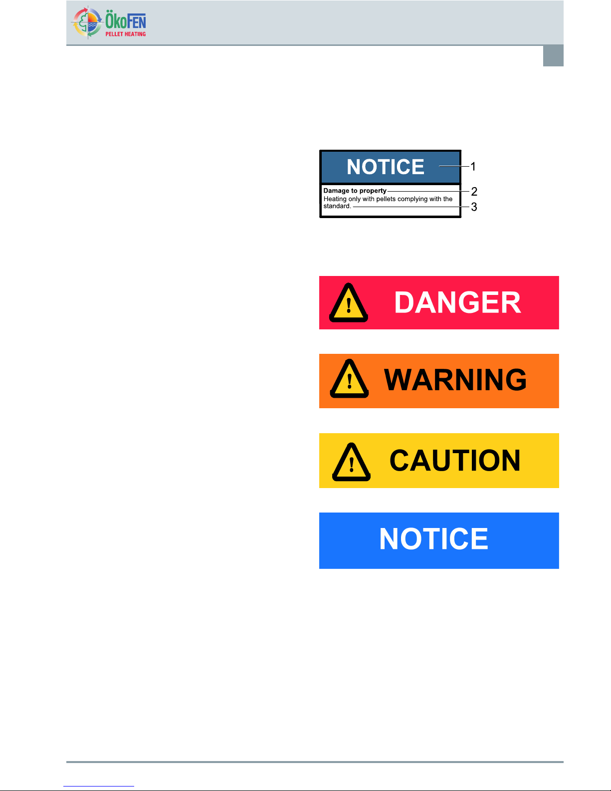
Thewarningsignsusethefollowingsymbolsandtext.
Typesofsafetywarningsign
1.Riskofinjury
2.Consequencesofrisk
3.Avoidingrisk
1.Riskofinjury:
Danger-indicatesasituationthatcouldleadtodeathor
life-threateninginjury.
Warning-indicatesasituationthatcouldlead
life-threateningorseriousinjury.
Caution-indicatesasituationthatcouldleadtoinjury.
Note-indicatesasituationthatcouldleadtoproperty
damage.
2.Consequencesofrisk
Effectsandconsequencesresultingfromincorrect
operation.
3.Avoidingrisk
Observingsafetyinstructionsensuresthattheheating
systemisoperatedsafely
E1389EN2.0
OperatingmanualPelletronicT ouch
Pelletronicheatingcontrollerandoperating
devicewithtouchscreen.
8
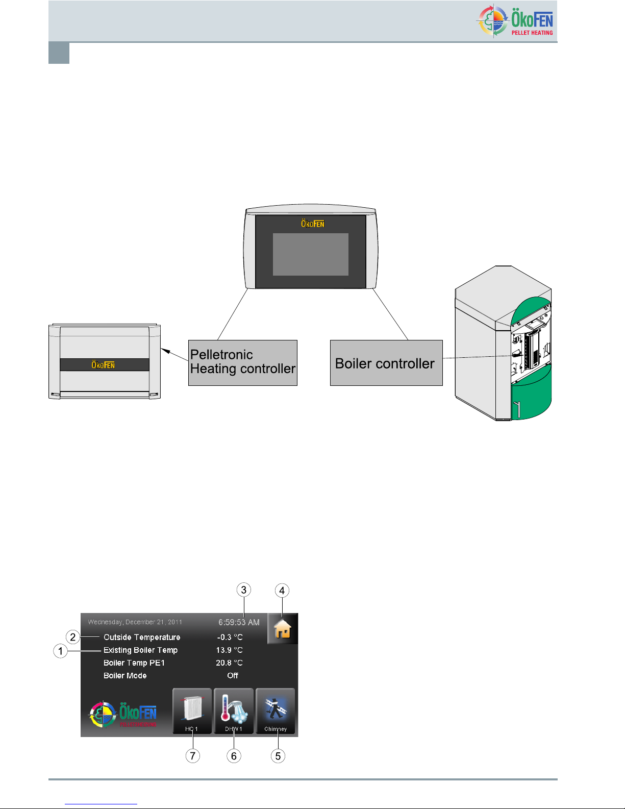
4Pelletronicheatingcontrollerandoperatingdevicewithtouch
screen.
Theheatingcontrollercontrolstheheatingsystemandregulatestheoperatingmodes,heatingcircuits,domestichot
water,accumulator,existingboilerandthesolarthermalsystem.Allinputsandoutputsareconnectedwiththeheating
controller.Visualisationandoperationoftheheatingcontrollerisdonewiththeoperatingdevicewithtouchscreen.It
displaysallmenuoptionsandmeasuringvaluesoftheheatingcontroller.Allspecicsettingsoftheheatingsystemis
donewiththeTouchoperatingdevice.
4.1OperatingDevicewithTouchscreen
TheTouchoperatingdeviceismountedonthecontrolboardofPellematic.The4.7"colordisplayissurroundedby
adesignfoilwithlogo.ApplyngerpressuretooperatetheT ouchscreen.
4.2Openingwindow
Thetouchpanelisdarkwheninstandbymode.Assoonasthesurfaceofthescreenistouched,itlightsupand
displaystheopeningwindow.
1Boilertemperature
2
Outsidetemperature
3Hour
4Theiconhousetakestothemainmenu.
5
Chimneysweep
6Favorite2
7
Favorite1
OperatingmanualPelletronicTouch
E1389EN2.0
Pelletronicheatingcontrollerandoperating
devicewithtouchscreen.
9
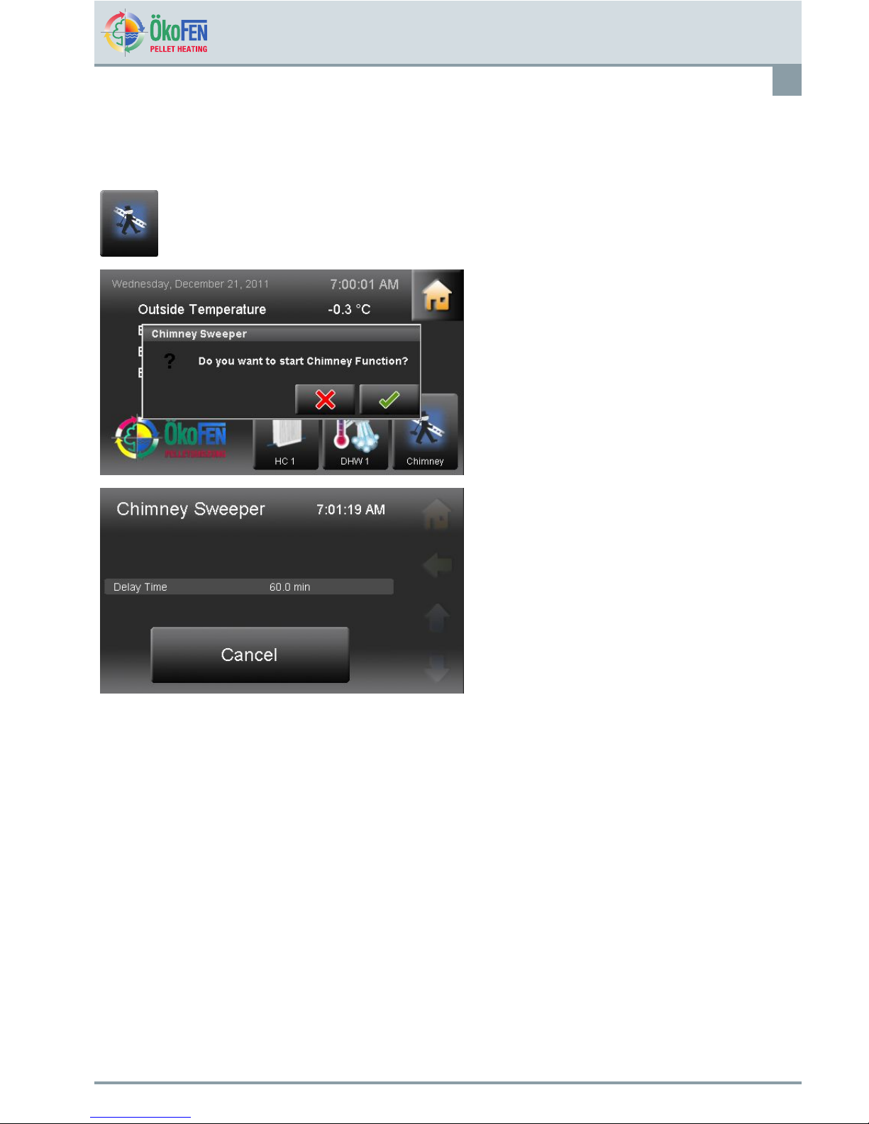
4.3Chimneysweep
ThefunctionChimneysweepisonlyforchimneysweeperorauthorisedservicetecnicians.Itisusedforexhaust
gasmeasurement.
MenuChimneysweepisintheopeningwindow.
Afterselectingthechimneysweepfunctionitwill
querywhethertoexecute.Ifyesthenpressthetick
box.
•Boilertemperaturesetis60°Cforthetotalrunning
timeof30minutes.
•Itdisplaystheactualboilertemperatureanddelay
time.
•ChimneysweepisstoppedwithCancel.
E1389EN2.0
OperatingmanualPelletronicT ouch
Pelletronicheatingcontrollerandoperating
devicewithtouchscreen.
10
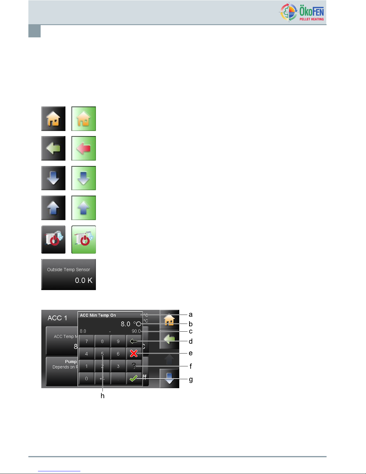
4.4Usercontrolsandtheirfunction
1.Howtonavigatetotherightmenu
Navigation-icons
Iconview
chosen
Iconview
Ifyoutouchanicon,thaticonturnsgreen.Thisindicatesthattheitemisselectedand
enablesthatfunction.
Theyellowhomesymboltakesyoudirectlytothemainmenu.
Thehorizontalarrowtakesyouonestepback.
Withthebluedownarrowyougettoadditionallinesofinformationonthisitem.(Down
-scrolldown).
Withtheblueuparrowyougettoadditionallinesofinformationonthisitem.(Topof
page-scrollup)
Navigatetotherespectivemenuitem.
Oncetherespectiveitemhasbeenselectedthenparametersmaybeset.Itwilldisplay
eitheranumericortextkeypad.
2.Numerickeyboard
a.Nameofparameter
b.Valueofparameterwithunit
c.Min/maxvalue–Valuesoutsidethisrange
arenotaccepted.
d.Deleteinputofnumbers–touchonceto
deleteoneplace.
e.Cancel–Youreturntothemenuitem.Input
ofanewvaluewasnotaccepted.Theoriginal
valueisthenrestored.
f.Helpfunction–inactive
g.Conrm
h.Numerickeyboard–usedtoentervalues
withintheMin-Maxrange.
OperatingmanualPelletronicTouch
E1389EN2.0
Pelletronicheatingcontrollerandoperating
devicewithtouchscreen.
11
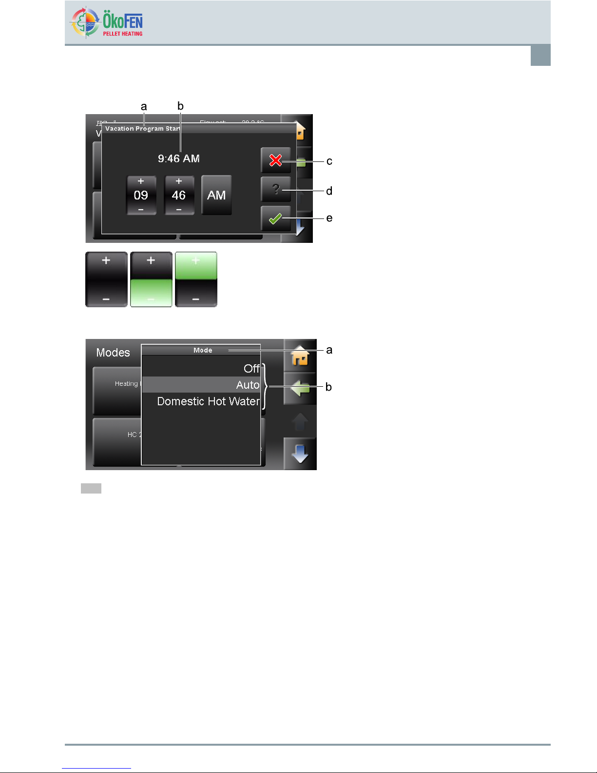
3.Timeanddateblock
a.Nameofparameter
b.Adjustabletimeordate
c.Cancel
d.Helpfunction–inactive
e.Conrm
WiththePlusMinusblockyouchangenumbers.
4.Textselection
a.Nameofparameter
b.Statustexts
Thenumberofstatustextsdependsonthe
parameter.
Chooseastatustext.Thesetupmenucloses
automaticallyandthechosenstatustextis
displayedinthemenu.
Note
Althoughascrolldownmenuisopen,thenavigation/parametericonsbehindarestillactiveandcanbeused.
E1389EN2.0
OperatingmanualPelletronicT ouch
Pelletronicheatingcontrollerandoperating
devicewithtouchscreen.
12
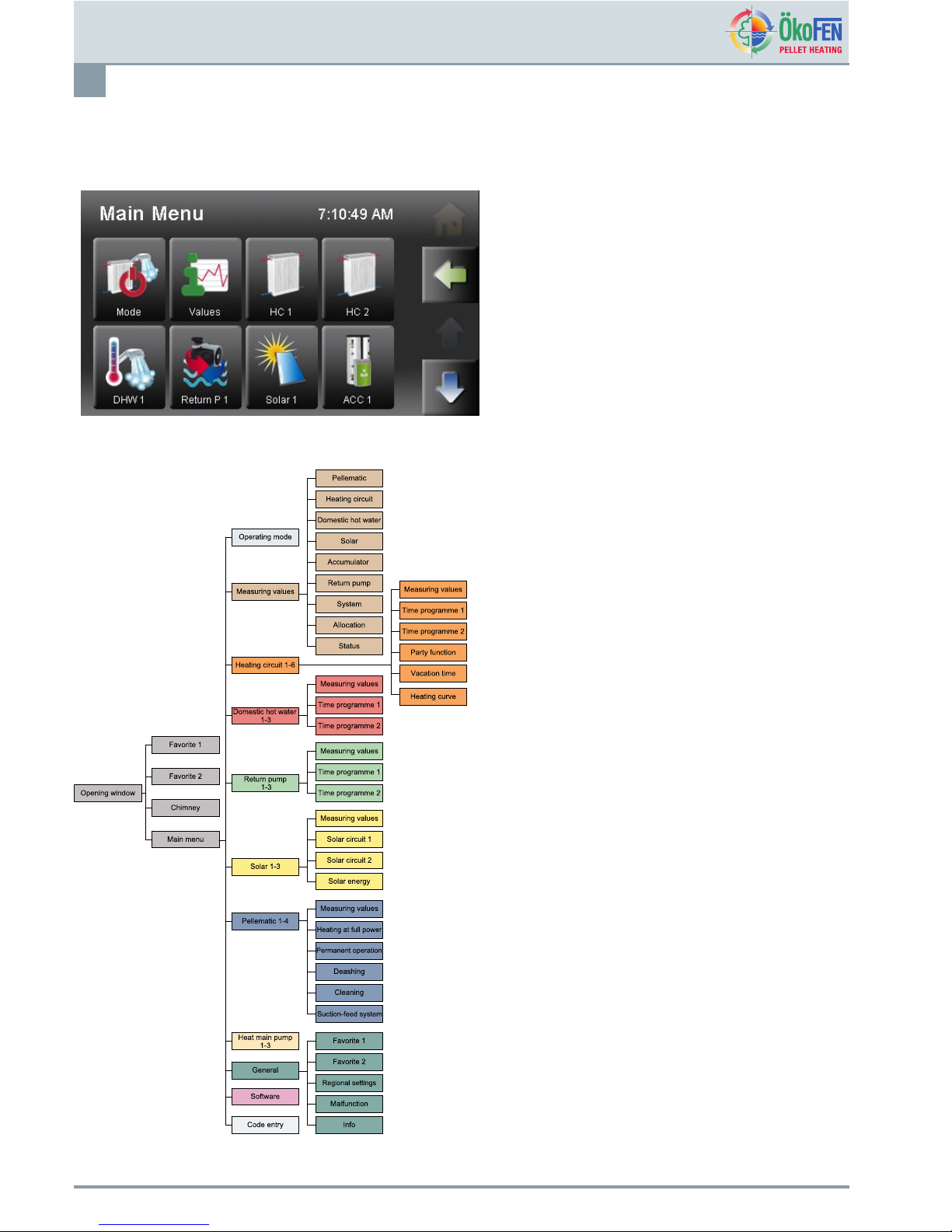
4.5MainMenu
Inthemainmenuallsubmenusaredisplayed.Presstheiconrequiredtoaccessthatprogramme.
MenunavigationofPelletronicTouch
OperatingmanualPelletronicTouch
E1389EN2.0
Mode
13
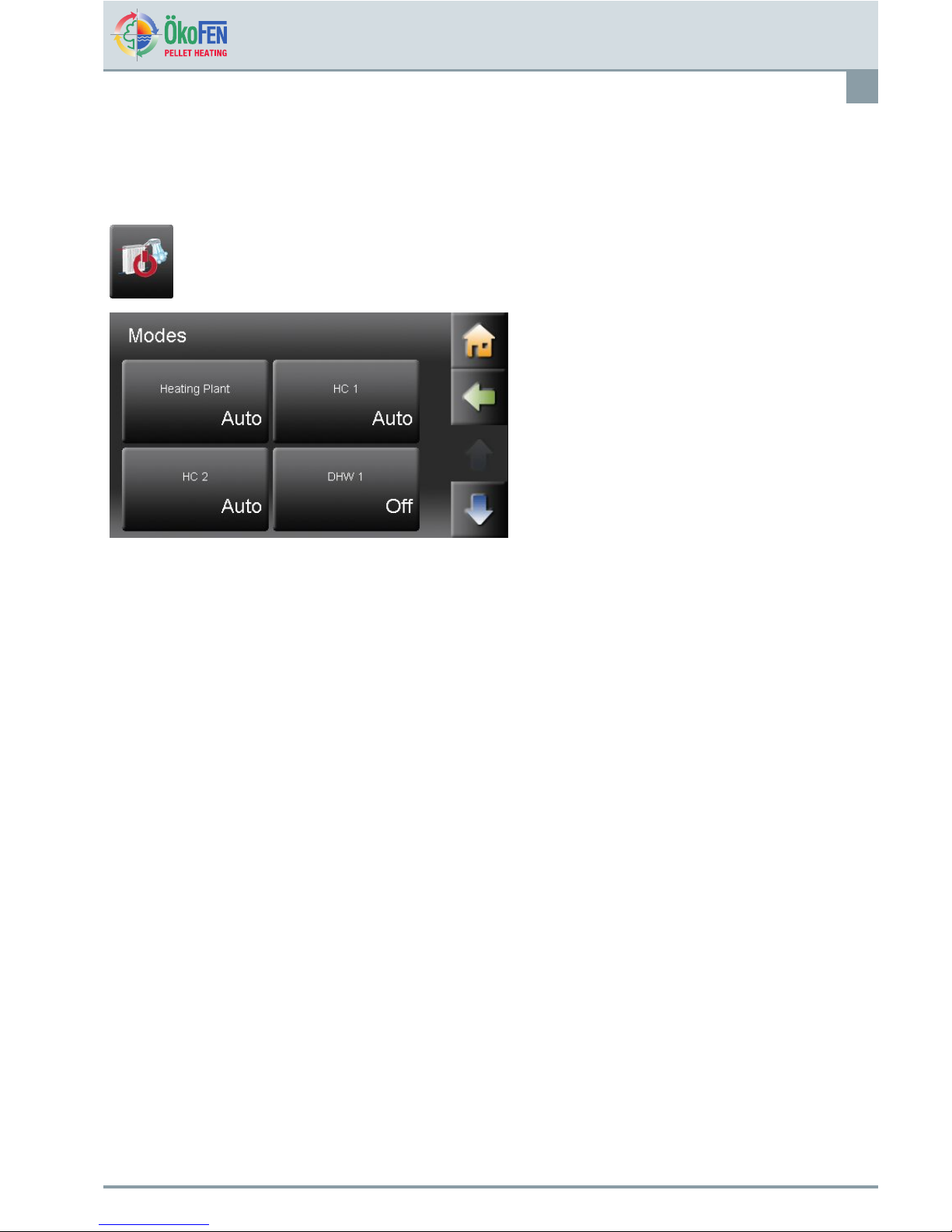
5Mode
InthemenuitemModesyoucanseetheoperatingmodeoftheheatingsystem,heatingcircuits,domestichotwater
andsolar.
ThemenuitemModeisintheMainmenu.
Overviewoftheoperatingmodes
•HeatingPlant
•Heatingsystem1-6.
•Domestichotwater1-3
•Solar1–3
Choosetheoperatingmodeandsetaccordingly.
OPERATINGMODESSYSTEM
OffTheadjustedoperatingmodeoftheheatingcircuitsandDHWisinactive.
Thefrostprotectionfunctionisactive.
Auto
TheadjustedoperatingmodeoftheheatingcircuitsandDHWisactive.
Thefrostprotectionfunctionisactive.
Domestichotwater
TheadjustedoperatingmodeoftheDHWisactive.
Theadjustedoperatingmodeoftheheatingcircuitsisactive.
Thefrostprotectionfunctionisactive.
Theoperatingmodeheatingcircuits,domestichotwaterandsolararedescribedintherespectivechapters.
E1389EN2.0
OperatingmanualPelletronicT ouch
MeasuringValues
14
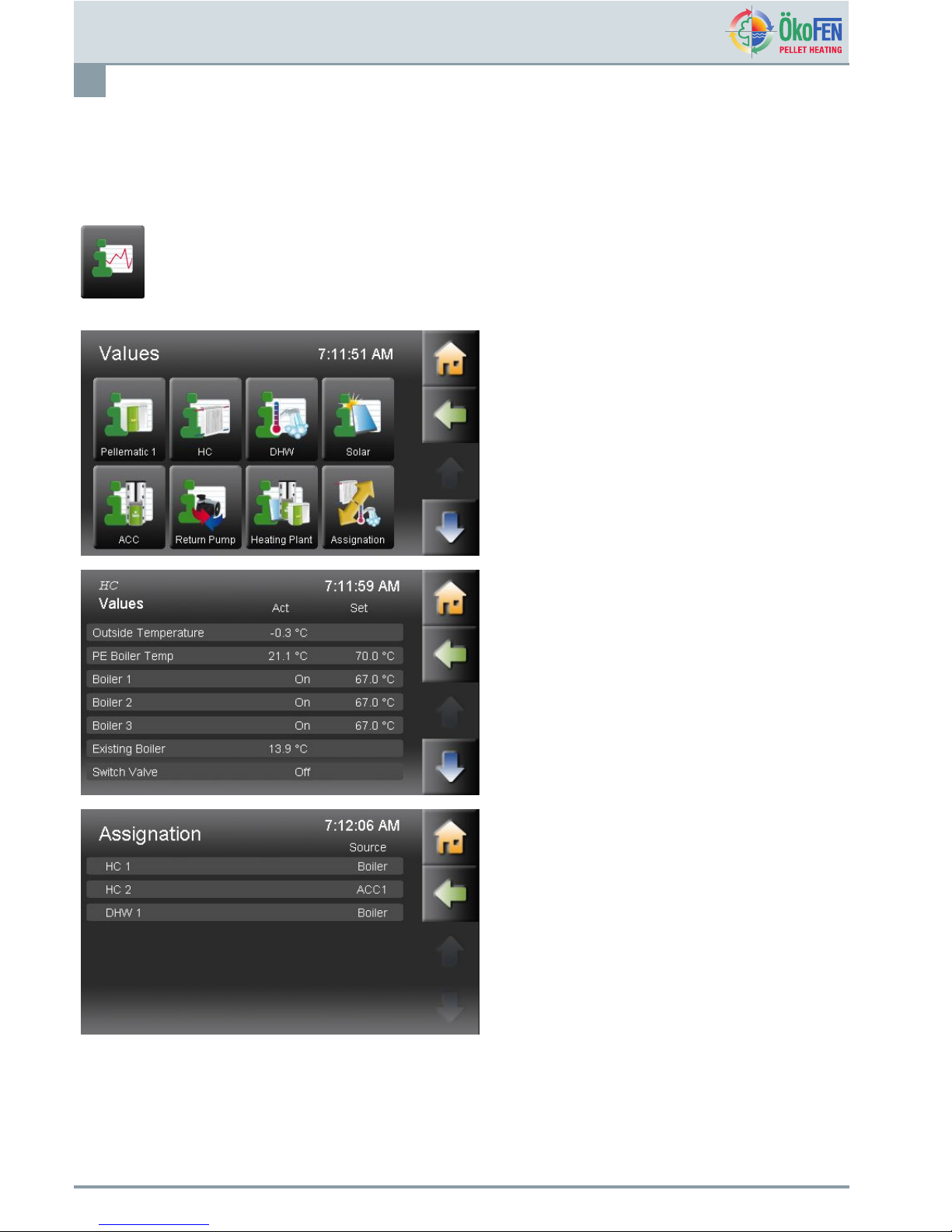
6MeasuringValues
InthemenuitemV aluesyoucanviewcurrentsettingsorsetnewvaluesfortheheatingcircuit,domestichotwater,
accumulatororsolar.
ThemenuitemMeasuringValuesisintheMain
menu.
Selecttheappropriatesubmenu.
InthemenuitemHeatingcircuityouseeallactual
andsetvaluesoftheheatingcircuitsinyourheating
system.
InthemenuitemDomestichotwateryouseeall
actualandsetvaluesoftheDHWproduction.
InthemenuitemSolaryouseeallactualandset
valuesofthesolarthermalsystem.
InthemenuitemAccumulatoryouseeallactualand
setvaluesoftheaccumulator.
InthemenuitemSystemyouseeallactualandset
valuesoftheoverallheatingsystem.
InthemenuitemAllocationyouseewhich
heatingcircuitsareallocatedtotheboilerortothe
accumulatores.
OperatingmanualPelletronicTouch
E1389EN2.0
MeasuringValues
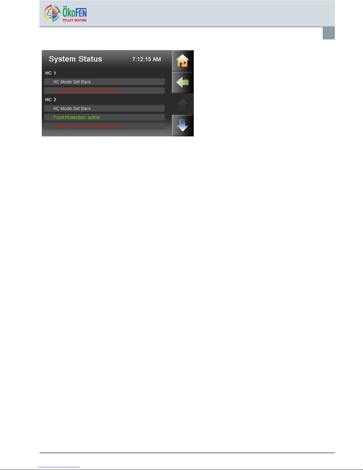
15
SystemStatusisanoverviewofthewholeheating
system.
E1389EN2.0
OperatingmanualPelletronicT ouch

HeatingCircuit
16
7HeatingCircuit
HeatingCircuitcontainsallrelevantparametersandsettings.Itcanoperateupto6heatingcircuits.
HeatingCircuitisintheMainmenu.
HeatingCircuithasfollowingmenuitems:
•Mode
•RoomTempHeating
•RoomTempSetback
•TimeAllocation
•Values
•Time1
•Time2
•Party
•Vacation
•HeatingCurve
Mode
OffOnlythefrostprotectionfunctionisactive.
AutoTheboilerstartsheatingautomaticallyaccordingtothesetroom
temperature.
Heating
TheboilerheatsconstantlyaccordinglytotheSetroomtemperature.
SetbackTheboilerheatsconstantlyaccordinglytotheSetbackroom
temperature.
Theoperatingmodeoftheheatingcircuitscanonlybechangediftheplantoperatingmode
issettoAUTO.
Theadjustedheatinglimitsandmaximumowtemperaturesareusedinalloperating
modes.
RoomTempHeating
Chooseyourroomtemperature(Temperaturewithintheheatingtimes).
RoomTempSetbackChooseRoomT empSetback(=Minimumtemperaturebeyondtheheatingtimes).
TimeAllocation
ActivateTime1(=Timeprogramme1)andTime2.
OperatingmanualPelletronicTouch
E1389EN2.0

HeatingCircuit
17
7.1MeasuringvaluesHeatingcircuit
MeasuringvaluesHCisintheMainmenu.
Thisdisplaysallcorrespondingheatingcircuitvalues:
•Actualvalue
•Setvalue
•Inputs(sensores)
•Outputs(pumps,mixerandmotors)
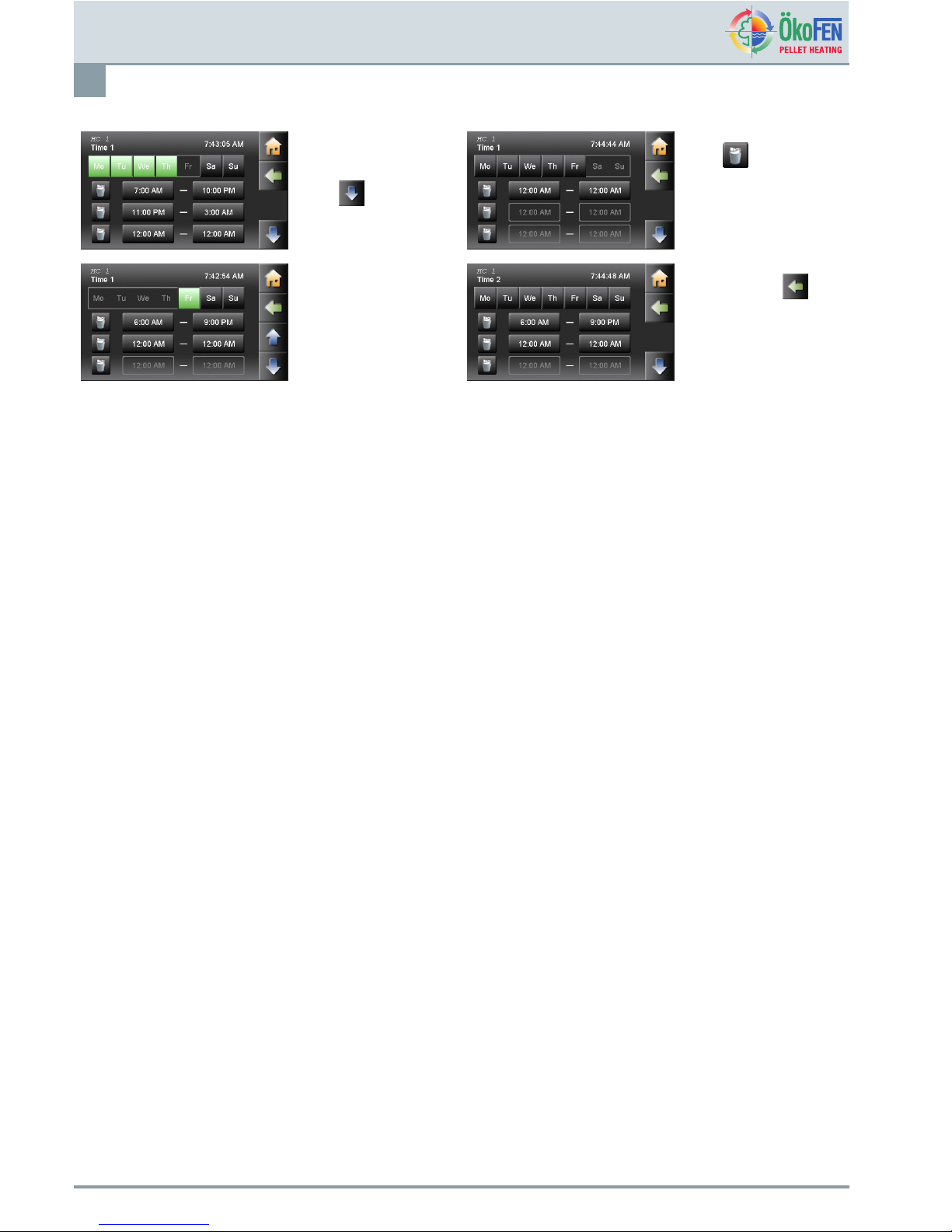
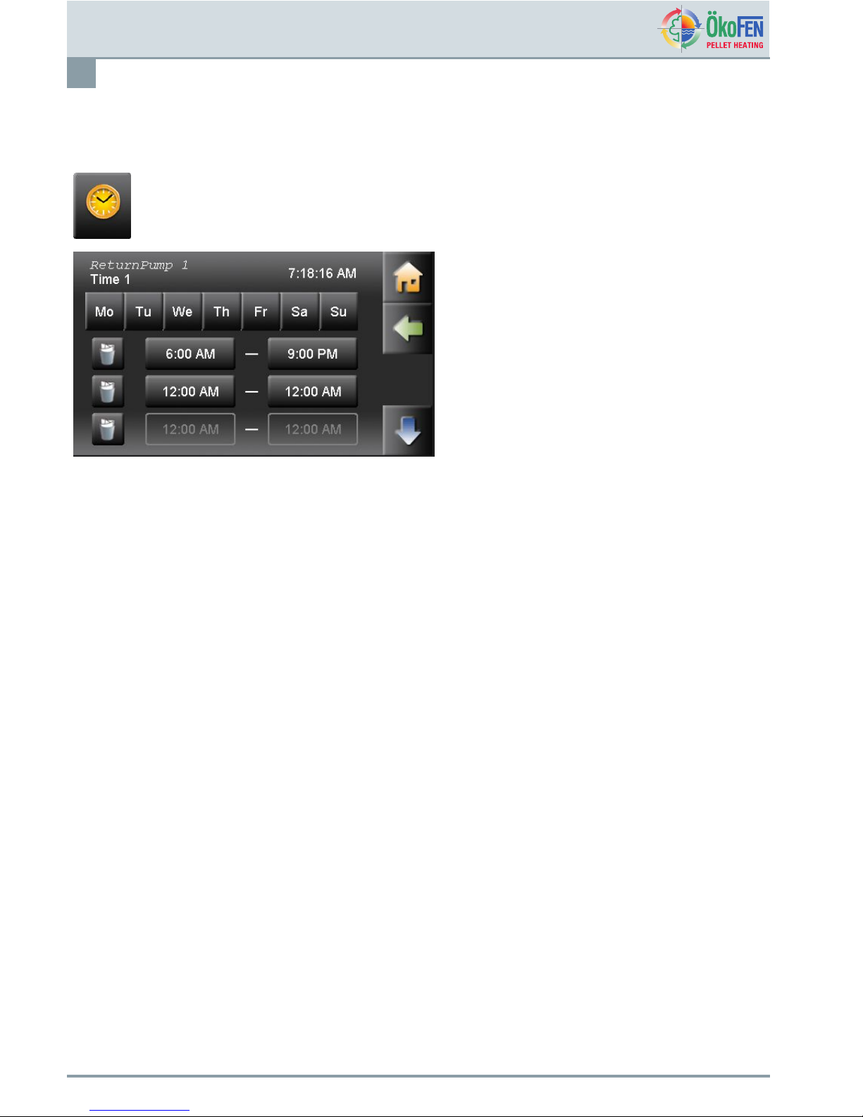
7.2TimeprogrammeHeatingcircuit
Theheatingcircuitprogrammeisusedtosettheheatingtimes.
Time1(=Timeprogramme1)andTime2areinthemenuHeatingcircuit.
1
SelectTime
programme1
6
Mo-Frwereassigned
heatingtimes
Withyougettothe
remainingdaysSa-Su.
2
Selecttheheating
days.
Theactivateddaysare
displayedingreen.
7
Sa-Suwereassigned
toheatingtimes.
3
Entertheheatingtimes
fortheseheatingdays
(Mo-Th).
8
Withand
youswitchbetween
theheatingblocks.
Youcanactivateor
deactivateheating
daysintheheating
block.
E1389EN2.0
OperatingmanualPelletronicT ouch
HeatingCircuit
18
4
Theheatingtimesfor
Mo-Thareassigned.
Withyouassign
thedaysheatingtimes
further.
9
Withyousetallthe
heatingtimesintheline
andbelowto0.
5
Fridayisactivated
andheatingtimes
assigned.
10
Gobackwith.
SelectTime2.
Foreachcircuitaretwo
timeprogrammes.You
canselecttwo-time
programs.Inthemenu
itemTimeAllocation
youcanactivateTime
programme1or2.
OperatingmanualPelletronicTouch
E1389EN2.0
HeatingCircuit
19
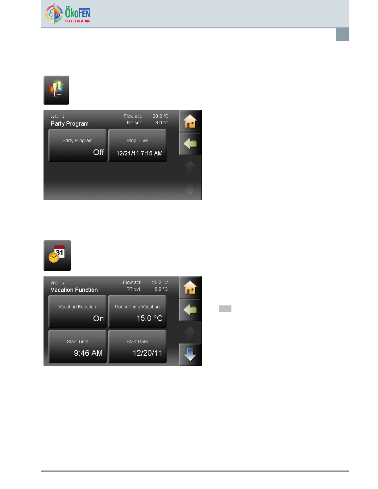
7.3Party
Thepartyfunctionextendstheheatingtimeonce,withoutchangingtheheatingtimes.
PartyisintheMainmenu.
Thepartyfunctionisbasicallyinactive.Enterthe
requiredstoptimethattheroomshouldbeheated
until.ActivatethePartyfunction.
Theheatingtimeisextendeduptotheindicated
time.Thenthepartyfunctiondeactivatesitself
automatically.
7.4Vacation
Theholidayprogrammecancelstheheatingtimesandheatsfortheenteredperiodonthesettemperaturelevel.
VacationisintheMainmenu.
Entertheroomtemperatureonwhichinyourabsence
thebuildingshouldbeheated.Enterthedeparture
(starttime)andreturn(nishdate)andactivatethe
vacationprogramme.
Note
Toreturntoanalreadytemperatebuilding
youshouldenterthedaybeforeyourreturn
asthenishdate.
E1389EN2.0
OperatingmanualPelletronicT ouch
HeatingCircuit
20
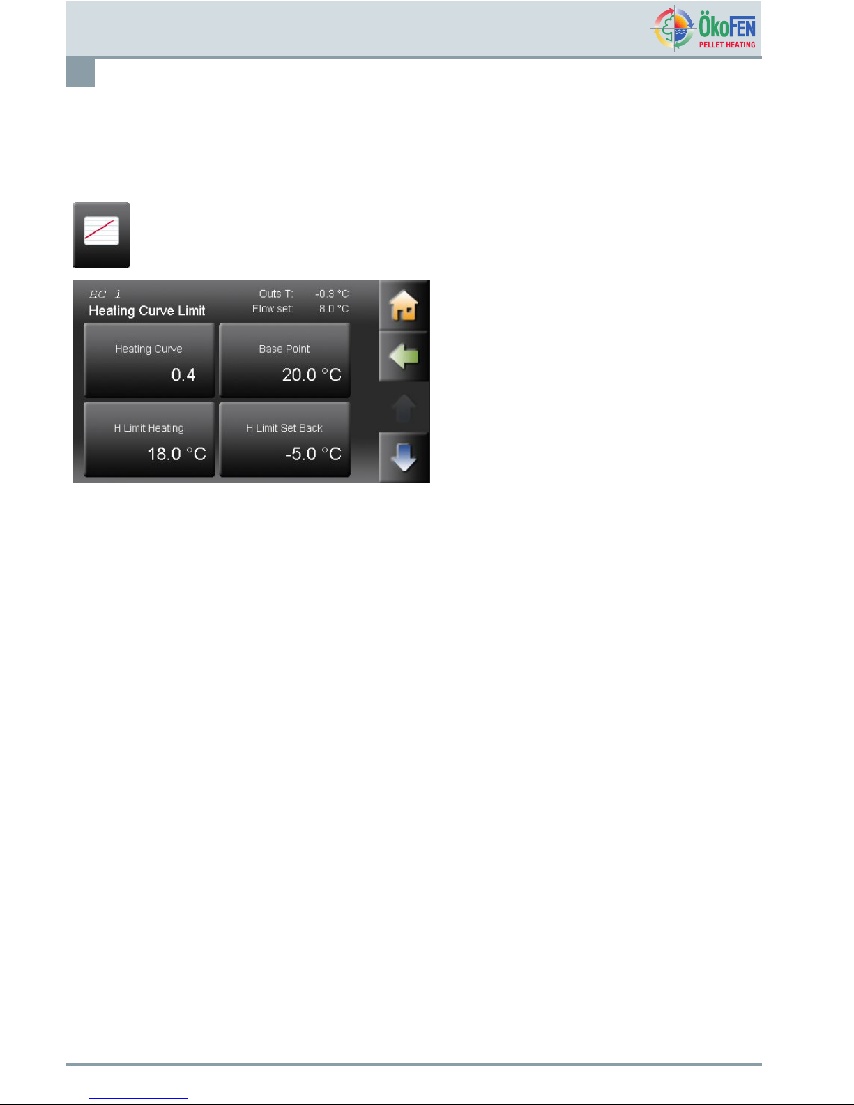
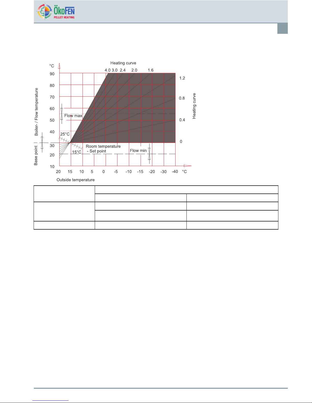
7.5HeatingcurveandHeatinglimits
Startingupforthersttime,theauthorisedtechnicaladviseradjuststheheatingcurve,thebasepointandtheheating
limitsonthebuildingsituationandthehydraulics.IftheSetroomtemperatureisnotreachedorexceeded,adjustthe
heatcurvewiththeowtemperaturesaccordingtooutsidetemperatures.
HeatingcurveisinthemenuHeatingcircuit.
Heatingcurve0.0–4,0
Theheatingcurvedescribesthecombination
betweenoutdoortemperatureandtheassociatedow
temperatureforaheatingcircuit.
Basepointadjustablefrom20-45
Withthechangetheofbasepoint,youprovidea
parallelshiftoftheheatingcurve.
Hlimitheating
Iftheaverageoutsidetemperatureishigherthanthe
settemperature,theheatingcircuitswitchesoffinthe
heatingmode.
Hlimitsettemperature
Iftheaverageoutsidetemperatureishigherthanthe
settemperature,theheatingcircuitswitchesoffinthe
Setbackmode.
OperatingmanualPelletronicTouch
E1389EN2.0
HeatingCircuit
21
Adjustmentofheatingcurveandthebasepointtothebuilding
Becauseofthebuilding´sthermalinertia,itisrecommendedtoperformnomorethanoneadjustmentstepperday.
Roomtemperature Daytime
outsidetemp
toowarm
toocold
Decreaseheatingcurvingvalueby0.2Increaseheatingcurvingvalueby0.2
+5to+15°C
Decreasebasepointvalueby5°Increasebasepointvalueby5°
-20to+5°C
Decreaseheatingcurvevalueby0.2Increaseheatingcurvevalueby0.2
E1389EN2.0
OperatingmanualPelletronicT ouch
HeatingCircuit
22
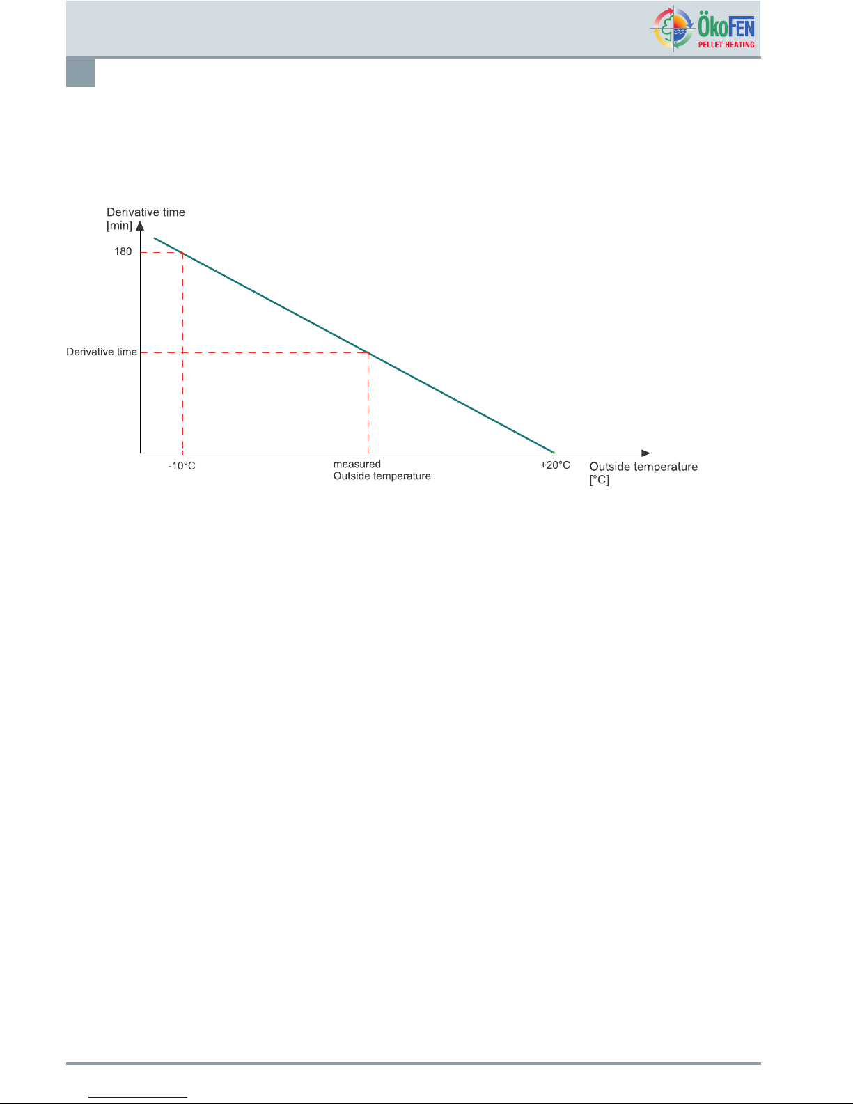
Advancedrunup:
Thisfunctionensuresthatthesetroomtemperatureisreachedbytheprogrammedheatingtimebystartingtheboiler
early.Thegureyousetisamaximumandwillbereducedbythecontrollerdependingontheoutsidetemperature
asshowninthegraphbelow.Wesuggest180minsforunderoorheatinginscreedand60-80minsformostradiator
systems.[useradjustable]
Roomthermostatinuence
Ifthemeasuredroomtemperaturedeviatesfromthesetroomtemperatureitcorrectstheheatingcontrollerandtheow
temperaturewiththeroomthermostatinuence.
TheRoomthermostatinuenceindicateshowmuchtheowtemperatureisraisedorloweredsothattheSetroom
temperatureisreached.
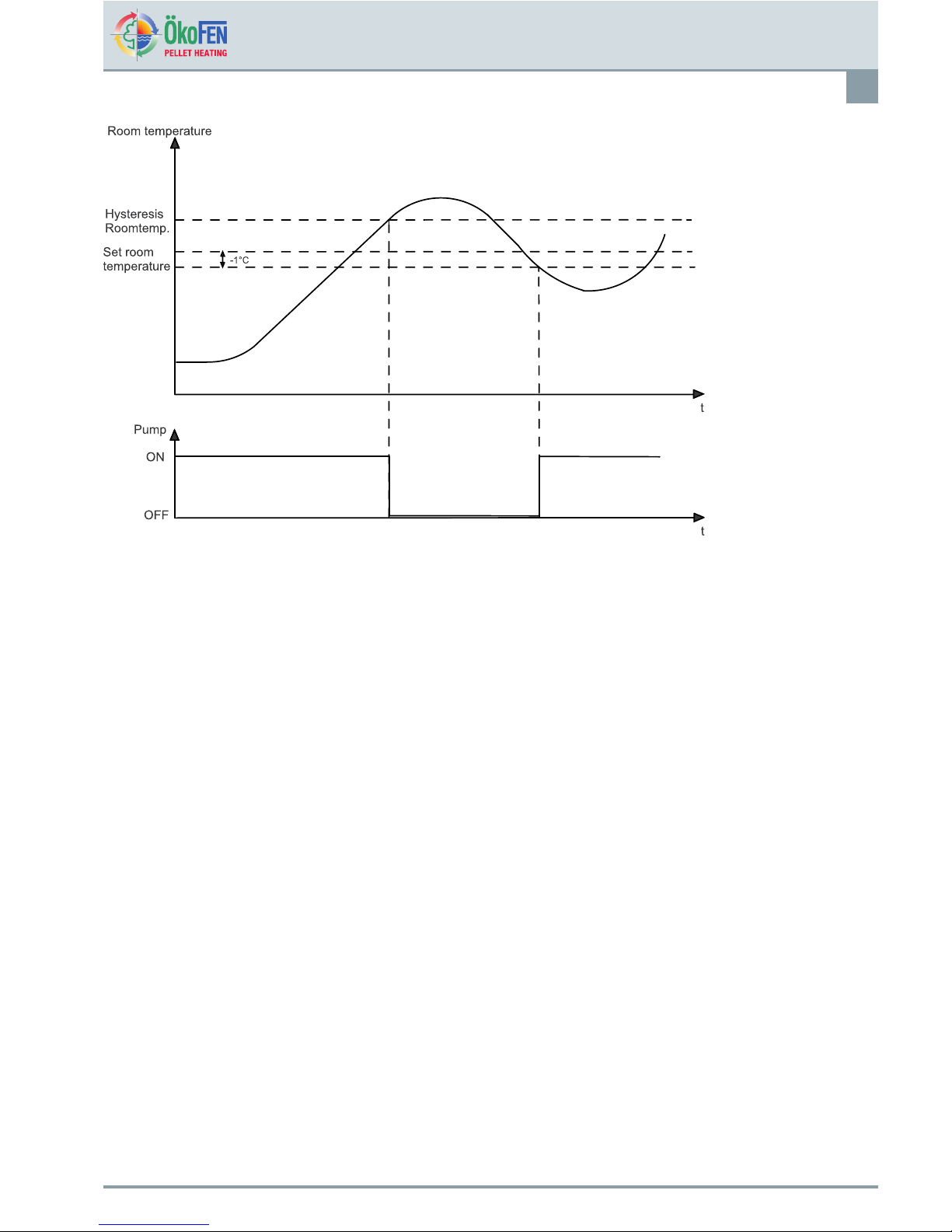
Roomtemperaturehysteresis
Theroomtemperaturehysteresispreventsthecycling(OnOffOnOff...)oftheheatingcircuitpump:IftheSetroom
temperature+roomtemperaturehysteresisisreached,theassociatedpumpstops.IftheSetroomtemperatureis–
1°C,thepumpswitchesonagain.
OperatingmanualPelletronicTouch
E1389EN2.0
HeatingCircuit
23
E1389EN2.0
OperatingmanualPelletronicT ouch

HeatingCircuit
24
7.6Screedprogramme
Thescreedprogrammemaybeoperatedupto31days.
Adesiredowtemperaturemustbeadjustedforeachindividualday.Thesetemperaturesareconstantandnot
dependentonoutsidetemperatureorroomthermostatsettings.Thefunctionisswitchedoffautomaticallyattheendof
theprogrammeandtheheatingcircuitrevertstothepreviousoperatingmode.
Damagestothescreedbytoohightemperatures.
Onlyusethisprogrammeinconjunctionwithapump
interlockswitchpositionedontheowfrompump
tounderoorcentralheating–thismustbesettothemax.
safetemperaturefortheconditionsoftheoor.No
libilityisacceptedbythePelletronicsupplierfordamage
tooorsorsuboors.
Continuouspowersupplyisrequiredtothecontrollerto
maintainthesettingsforthisprogramme.
OnlyuseprogrammetemperaturesapprovedbytheUFCH
andooringsuppliers.
ScreedprogrammeisinthemenuHeatingcircuit.
Attheendofthescreedprogrammeitwillswitchitself
offautomaticallyandreturntothepreviousmode.
Enterthenumberofheatingdays.Thereare0-31
heatingdayspossible.Accordingtothenumberof
heatingdaysaFlowtemperaturesetappearsfor
everyheatingday.
SelecteverysingledayandadjusttheFlow
temperatureset.Thepre-setFlowtemperatureset
perdayis20°C.
With
yougettoallotherdays.
OperatingmanualPelletronicTouch
E1389EN2.0
Domestichotwater(DHW)
25
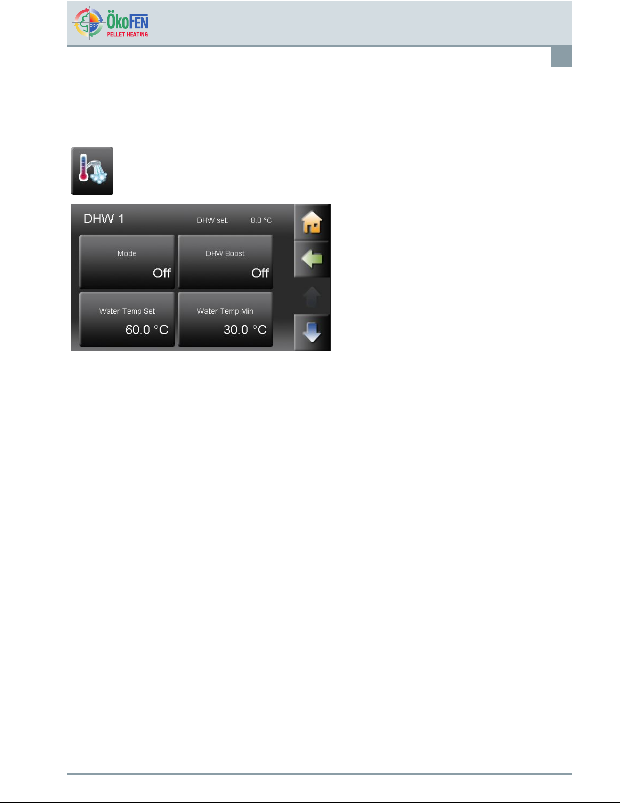
8Domestichotwater(DHW)
ItcanoperateuptothreemenuitemsinDHW.Domestichotwaterincludesallparametersandsettingsforhotwater
production.
DHWisintheMainmenu.
DHWhasfollowingmenuitems:
•Mode
•DHWBoost
•WaterT empSet
•WaterT empMin
•Values
•Timeprogramme
•Time1
•Time2
Mode
OffSetwatertemperatureisreducedto8°forfrostprotection.
AutoDomestichotwaterwillbeheatedtothesettemperatureduringtimeperiods.
OnThesystemheatsupthedomestichotwatercontinuouslyontheWatertempset.
YoucanchangethemodedomestichotwateronlywhentheOperationmodeison
AUTO.
DHWBoostHeatsthehotwateronceontheWatertempset.
WaterTempSetSetthewatertemperature.
WaterTempMin
Settheminimumwatertemperature.Thewatertemperatureneverfallsbelowthisvalue,
unlessthedomestichotwatermodeisOFF.
ValuesYouseealltheDHWcorrespondingmeasuringvalues.
Timeprogramme
ActivateTime1(=Timeprogramme1)andTime2.
Time1andTime2
IntheDHWtimeprogrammeyousetthetimesofthehot-waterprocessing.TheDHW
timeprogrammeworksthesamewayastheheatingcircuitprogramme.Seechapter7.2
TimeprogrammeHeatingcircuit,page17
E1389EN2.0
OperatingmanualPelletronicT ouch
Domestichotwater(DHW)
26
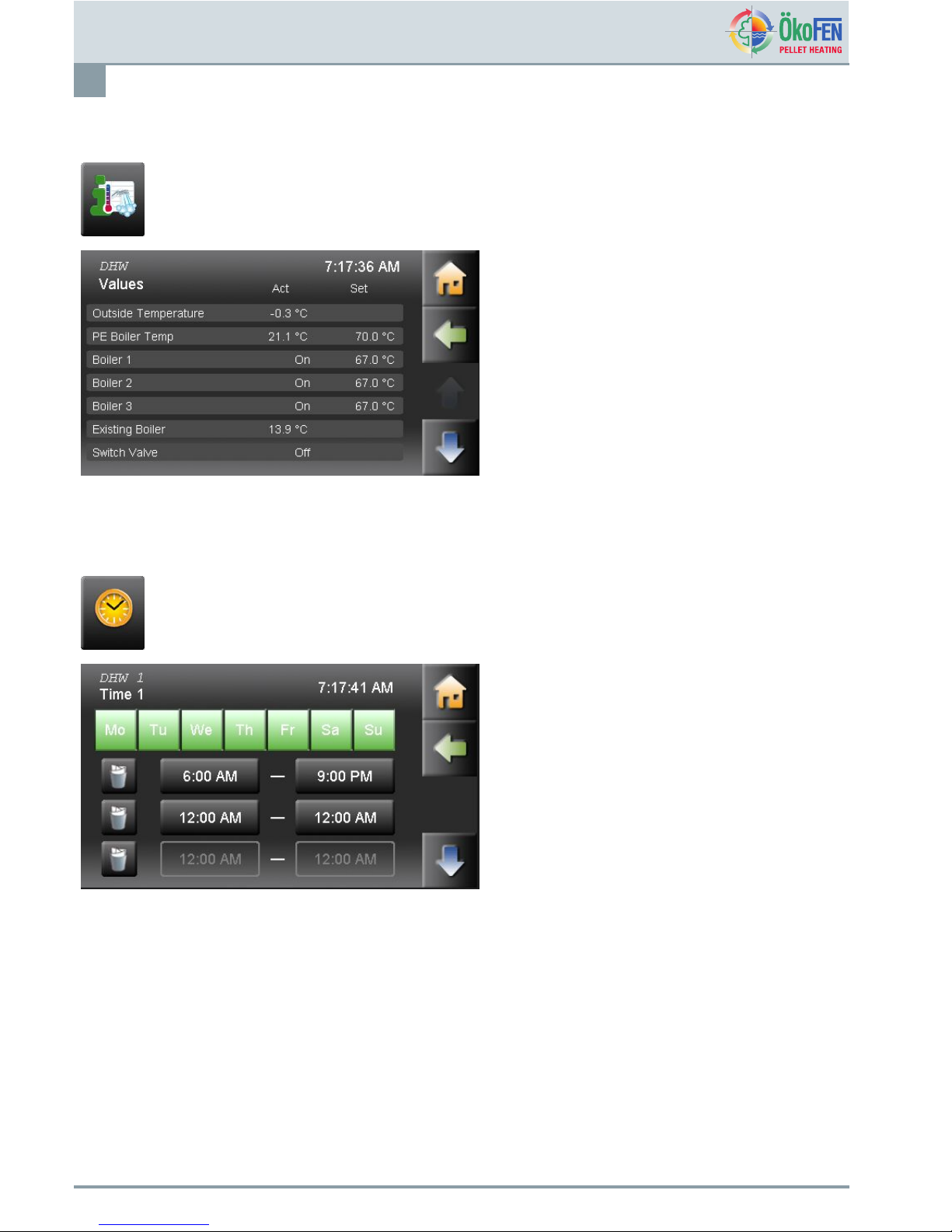
8.1MeasuringvaluesDomestichotwater
MeasuringvaluesDHWisintheMainmenu.
Displayedareallthecorrespondingmeasuring
values:
•Actualvalue
•Setvalue
•Inputs(sensores)
•Outputs(pumps,mixerandmotors)
8.2TimeprogrammeDHW
IntheTimeProgrammeDHWreturnpumpyousettheDHWusagetimes.
Time1(=Timeprogramme1)andTime2areinthemenuDomestichotwater.
Thedomestichotwatertimeprogrammeworksthe
samewayastheheatingcircuittimeprogramme.
Seechapter7.2TimeprogrammeHeatingcircuit,
page17
OperatingmanualPelletronicTouch
E1389EN2.0

DHWReturnpump
27
9DHWReturnpump
DHWReturnpumpisintheMainMenu.
TheReturnpumpenablestheimmediateuseofhot
water.DHWReturnpumphasfollowingmenuitems:
•Mode
•Switchofftemperature
•Switchonhysteresis
•Timeallocation
•Values
•Time1
•Time2
Mode
Off…DHWReturnpumpinactive
Auto…Temperatureregulationwithinthetimeprogramme
SwitchofftemperatureIfthereturntemperaturesensoroftheDHWReturnpumpreachestheSwitchoff
temperature,thepumpswitchesoff.
SwitchonHysteresisIfthereturntemperaturefallsbelowtheswitchofftemperature–theDHWReturn
pumpswitchesonagain!
TimeAllocation
Choosethetimeprogramme1or2.
ValuesYouseealltheDHWpumpcorrespondingmeasuringvalues.
Time1,Time2
IntheReturnpumptimeprogrammeyousettheruntimesoftheReturnpump.The
Returnpump–timeprogrammeworksthesamewayliketheheatingcircuittime
programme.
Seechapter7.2TimeprogrammeHeatingcircuit,page17
9.1MeasuringvaluesDHWReturnpump
MeasuringvaluesDHWReturnpumpisinmenuDHWReturnpump.
YouseealltheHeatingcircuitcorresponding
measuringvalues:
•Actualvalue
•Setvalue
•Inputs(sensores)
•Outputs(pumps,mixerundmotors)
E1389EN2.0
OperatingmanualPelletronicT ouch
DHWReturnpump
28
9.2TimeprogrammeDHWreturnpump
IntheTimeProgrammeDHWreturnpumpyousettheDHWusagetimes.
Time1(=Timeprogramme1)andTime2areinthemenuDHWreturnpump.
TheDHWreturnpumptimeprogrammeworksthe
samewayastheheatingcircuittimeprogramme.
Seechapter7.2TimeprogrammeHeatingcircuit,
page17
OperatingmanualPelletronicTouch
E1389EN2.0
Solar
29
10Solar
Solarincludesallrelevantparametersandsettingsforthesolarthermalsystem.Youcancontrolupto6solarcircuits.
SolarisintheMainmenu.
Solarhasfollowingmenuitems:
•MeasuringvaluesSolar
•Solarcircuit1–2
•Solarenergy-Yield
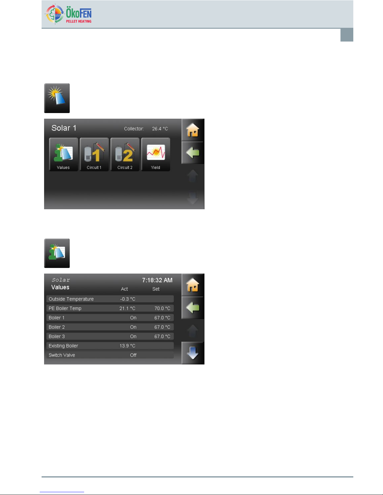
10.1MeasuringvaluesSolar
MeasuringvaluesSolarisinthemenuSolar.
ItdisplaysallmeasuringvaluesofSolar:
•Actualvalues
•Setvalues
•Inputs(sensors)
•Outputs(pumps,mixerandmotors)
E1389EN2.0
OperatingmanualPelletronicT ouch
Solar
30
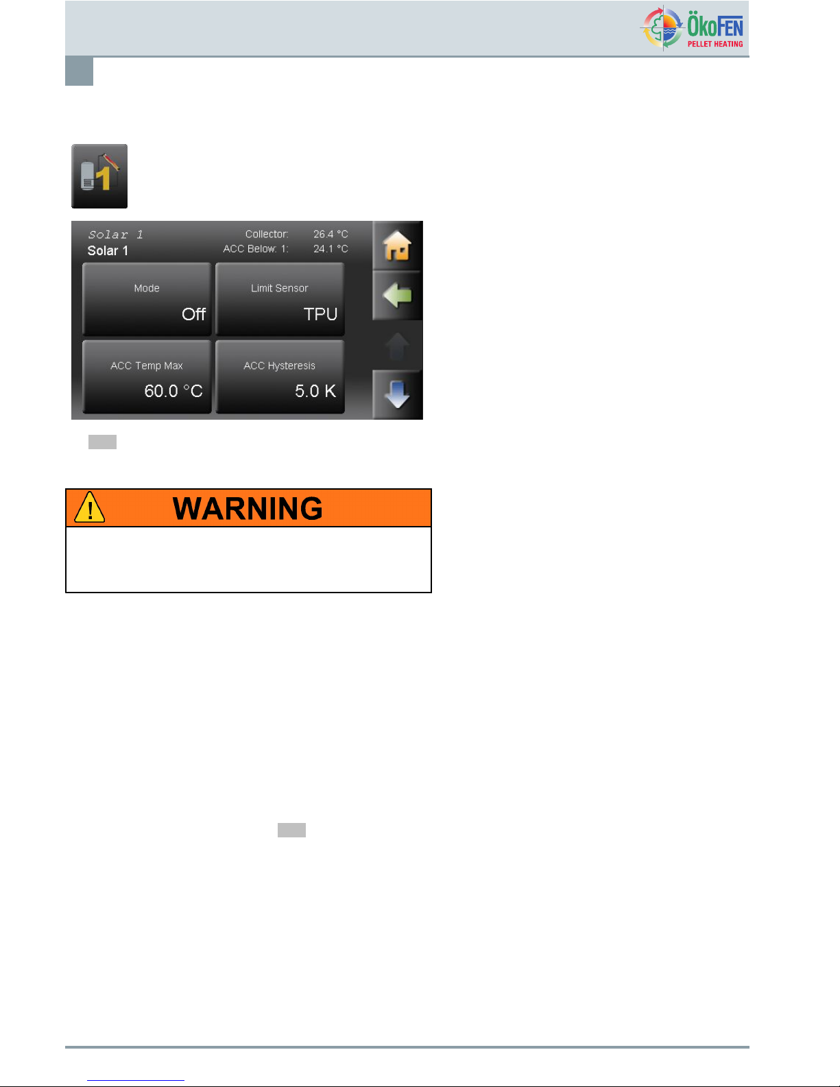
10.2Solarcircuit
Solarciruit1and2areinmenuSolar.
Solarcircuithastwooperatingmodes:
•ONCharge,aslongastheCollectortemperature+
hysteresisishigherthanthetemperatureoftheAC
lowersensororACtemperatureisreached.
•OFFNocharge
AslimitsensorchooseTPU,TPM,TPO,orDHW
sensor.
Note
Thesolarthermalsystemcanbeswitchedon/offirrespectiveoftheplantmode.
TheoperationmodeSOLARcanalsobechanged,iftheOPERATINGMODEPLANTissettoOFF!
VERYHIGHDOMESTICHOTWATERstorage
temperaturesarepossible!
Werecommendconsultingyourspecialistinstallerbefore
changingthesesettings.
ACCtempMaxIfthetemperatureintheACCishigherthantheACCtempMax,thesolarpump
switchesoff.ThelimitsensormeasuresthetemperatureintheACC.
ACCHysteresisThesolarcircuitpumpisswitchedoffduetotheACCtempMaxisreached.The
temperaturemustfallunderACCtempMaxminushysteresis,thenthesolarcircuit
pumpswitchesonagain.Thehysteresispreventsasolarpumpcycling(OnOff
OnOff).
CollectorHystOnIfbetweenthecollectorsensorandTPU,ACClowersensorthetemperature
differenceisgreaterthantheCollHystA,switchesthesolarpumpOn.
CollectorHystOffIfbetweenthecollectorsensorandTPU,ACClowersensorthetemperature
differenceissmallerthantheCollHystA,switchesthesolarpumpOff.
Collectorsmoothing
mode
Itonlyfunctionsonsolarcircuitone,itcanbeswitchedonandoffanditensuresan
efcientdeliveryofenergyfromthecollectors.
Note
Thiscanonlybeset,whenthespeedcontrolfunctionison.Settinginthe
codeprotectedparameter.
Collectorsmoothing
MinTemp
Atthistemperaturethesolarpumpstartstorunatminimumspeed.
Collectorsmoothing
Controlrange
Thepumpspeedincreaseswithinthesetrangeasthecollectortemperature
increases.
OperatingmanualPelletronicTouch
E1389EN2.0

Solar
31
10.3Yield-SolarEnergy
Thisfunctionmeasurestheyieldofthesolarthermalsystemanddisplayscurrentenergyandlogspreviousdays.
Note
Forthefunctionsolarenergyitisnecessarytoinstall:
•Pulsevolumemeter(mustbeconnectedto24VOLTandZ_IN)
•Flowtemperaturesensor
•Returntemperaturesensor
Yield-SolarEnergyisinthemenuSolar.
Yieldmeasuringofsolarenergyhasfollowingmenu
items:
•Actual
Displayofthecurrentsolarenergy,refreshesevery
60sec.
•Yield-Day
Displayoftodayssolarenergysince00:00.
•Yield-Daybefore
Displayoftheofyesterdayssolarenergy .
•Yieldsince
Displayofthesolarenergysincethelastsetdate.
•Flowrate
Displayofthecurrentowrate,refreshesevery
60sec.
•Flowtemperature
Displayofthecurrentowtemperature
•Returntemperature
Displayofthecurrentreturntemperature
E1389EN2.0
OperatingmanualPelletronicT ouch

Pellematic
32
11Pellematic
Pellematicincludesalltherelevantparametersandsettingsforthecontrolofthepelletboiler.
Thereareupto4Pellematicboilerspossible.
PellematicisintheMainmenu.
Pellematichasfollowingitems:
•MeasuringvaluesPellematic
•Permanentoperation
•Fullpower
•Burnerplatecleaning
•Boilercleaning
•Pelletlevel
11.1Permanentoperation
PermanentoperationisinthemenuPellematic.
Ifyouconrmthequery,youacitvatethefunction
Permanentoperation.
Firstofall,thespring-drivenmotoropensthere
protectionsystemattheburner-theprocesstakes
about2minutes.Afterthattheburnermotorrunsin
permanentoperationandtransportspelletstothe
burnerplate.Inheatingsystemswithaugerdelivery
itwillalsooperatetheextractionaugerinpermanent
operation.
OperatingmanualPelletronicTouch
E1389EN2.0

Pellematic
33
11.2MeasuringvaluesPellematic
MeasuringvaluesPellematicisinthemenu
Pellematic.
ItdisplaysallmeasuringvaluesofPellematic:
•Actualvalues
•Setvalues
•Inputs(sensors)
•Outputs(pumps,mixerandmotors)
BoilerTemperatureActualBoilerTemperature
Combustionchamber
sensor
ActualCombustionchambersensor.(Displayedonly,ifaNiCrNicombustion
chambersensorisconnected)
Boilerstatus
Displaystheactualstatusoftheboiler.
BurnerRunTimeS
Burnerruntimeintenthseconds.
BurnerRestTime
Resttimeoftheburnerintenthseconds.
BurnerFanSpeedBurnerFanSpeedinpercent.
FlueGasFanSpeedFlueGasFanspeedinpercent.
UWSpeedPowerofthepumpwithactivatedspeedcontrol.
BurnerContactStatus(On/Off)
KapRA
Capacitivesensoroftheburner
Status(On/Off)
KapZW
Capacitivesensoratthehopper
Status(On/Off)
Note
Defaultdisplayalwayswithsuctionsystem.
Displayalternativewithaugersystem.
FlameReturnGateStatus(On/Off)FlameReturnGate
ExistingBoiler
Status(On/Off)ExistingBoiler
IgnitionTemperature
Mintemperatureandconnectedcombustionchamberascriteriaforignition.
BurnerStartsNumberofBurnerStartsofthesystem
BurnerRunTimeHBurnerRunTimeinhours
AverageRunTime
AverageRunTimeaccordingtothenumberofignitions
NumberIgnition
NumberofIgnitionswithelectricalignition
IgnitionStickStatus(OnOff)IgnitionStick
MotorBCleaningStatus(OnOff)MotorBCleaning
E1389EN2.0
OperatingmanualPelletronicT ouch

Pellematic
34
RelayFaultSignalStatus(OnOff)RelayFaultSignal
MotorRA1
Status(OnOff)MotorRA1
MotorRES1Status(OnOff)MotorRES1
MotorBurnerAuger
Status(OnOff)MotorBurnerAuger
11.3FullPower
FullPowerisinthemenuPellematic
InthemenuitemFullPoweryoucanadjustthefuel
feed.
Fuelcorrection:
Theburneraugerruntimeiscalculatedautomatically
bythePLCdependingontheratedpowerandthe
boilersetpointtemperature.Theburnermotoris
controlledaccordingly.Y oucanreduceorincrease
thevaluecalculatedbythePLC10stepsupordown.
11.4De-ashingsystem
De-ashingsystemisinthemenuPellematic.
ThemenuitemDe-ashingsystemisavailableonly
whenDe-ashingsystemisconnected.Theactivation
isonlypossilbeafterenteringtheCodeforservice
tecnicians.Thede-ashingsystemandtheburner
platecleaningworkparallel.
•Minruntimeoftheboileruntilnextde-ashing
procedure.Valueadjustable
•AshdeliverytimeIstheruntimeoftheashauger.
Valueadjustable.
OperatingmanualPelletronicTouch
E1389EN2.0

Pellematic
35
11.5FreshWaterModule
FreshWaterModuleisinthemenuPellematic.
11.6BoilerCleaning
BoilerCleaningisinthePellematicmenu.
BoilerCleaninghasthefollowingmenuitems.
•Cleaning/Filling
•Cleaning2
•MinRunTime
•CleaningTime
Adjustthesuctionsystemaccordingtothedemandsofyourheatingsystem.
Cleaning/FillingThevaluetobesetisthetime(fullhour)atwhichtheboilercleaningsequenceis
performed.Onvacuumsystemsthehopperisalsolledatthesametime,regardless
ofwhetheritisemptyornot.
Cleaning2YoucansetinCleaning/Fillingasecondcleaningsequence.Thevaluetobeset
isthetime(fullhour)atwhichtheadditonalboilercleaningsequenceisperformed.
Example:20h=additionalboilercleaningsequenceperformedat20:00.Onvacuum
systemsthehopperisalsolledatthesametime,regardlessofwhetheritisempty
ornot.
Defaultvalue-1h:Itisnotperformedasecondcleaningsequence.
MinRunTime
MinRunTimeoftheboileruntilnextcleaningsequence.Valueadjustable.
CleaningTimeDurationoftheboilercleaningsequenceinseconds.Valueadjustable.
E1389EN2.0
OperatingmanualPelletronicT ouch

Pellematic
36
11.7SuctionSystem
SuctionSystemisinthePellematicmenu.
SuctionSystemhasthefollowingmenuitems:
•Cleaning/Filling
•FrequenceRAMotor
•PauseRAMotor
•Suctioninterval
Adjustthesuctionsystemaccordingtothedemandsofyourheatingsystem.
Cleaning/FillingThevaluetobesetisthetime(fullhour)atwhichtheboilercleaningsequenceisto
beperformed.
Thecleaningoftheboilerisperformedatthesametime.
InCleaning2asecondcleaning/llingsequencecanbeset.Thevaluetobeset
isthetime(fullhour)atwhichtheadditonalboilercleaningsequenceisperformed.
Example:20h=additionalboilercleaningsequenceperformedat20:00.Onvacuum
systemsthehopperisalsolledatthesametime,regardlessofwhetheritisempty
ornot.
FrequRAMotor
Frequencyforstorageroomsuctionsystemsinpulsemode,onlyforvacuum
systems.
PauseRAMotor
Pausetimeforstorageroomextractormotor-suctionsysteminpulsemode.If
pausetime=0thennopulsemode.
SuctionIntervalRuntimeofburneraugeruntilnextSuctionInterval.
Thehopperislledatthistimeregardlessofwhetheritisemptyornot.
OperatingmanualPelletronicTouch
E1389EN2.0

Pellematic
37
11.8Leveldetectionsystem
LeveldetectionsystemisinthePellematicmenu.
Leveldetectionsystemhasthefollowingmenuitems:
•Mode
TextileT ank
StorageRoom
CapacitiveSensor
•LimitValue
•CorrectionValue
Adjustthesuctionsystemaccordingtothedemandsofyourheatingsystem.
TextileTank
LeveldetectionsystemusingweighingcellsforFleXILOtextiletanks.
StorageRoom
Leveldetectionsystemusingweighingcellsatthehopperforstoragerooms.(only
forPellematicTypePES36–56)
CapacitiveSensor...Leveldetectionsystemusingacapacitivesensorforstorage
roomsandTextiletanks.
LimitValue
istheminimumweightforawarningmessage.V alueadjustable.Thewarning
messageappearsontheoperatingdeviceanddisappearswhenthellingweightis
abovethesetminimumweight.
ModeChoose:
CorrectionValue
OnlyifmodeFlexiTankorStorageroomischosen.Setthedisplayofthecurrent
weightto0byputtinginthenegativeofthecurrentweightshown
E1389EN2.0
OperatingmanualPelletronicT ouch

HeatMainPump
38
12HeatMainPump
HeatMainPumpisintheMainmenu.
TheHeatMainPumpisanadditionalpump,when
theboileroraccumulatorisseparatedfarfromthe
pumpstation.InthemenuitemComponent,youcan
assignanyorallcircuitstooperatewiththeHeatMain
Pump.TheHeatMainPumprunswithanyassigned
pump.
SwitchtheHeatMainPumpOnorOff.
Note
ForeachheatingcontrolleronlyoneHeat
MainPumporcirculationpumpcanbeused.
TheHeatMainPumpandthecirculation
pumpareclosedfromeachother.
OperatingmanualPelletronicTouch
E1389EN2.0

General
39
13General
Generalincludesthecompleteheatingcontrolrelatedsettingsandindividualoperatingoptionsforthecustomer.
GeneralisintheMainmenu.
ThemenuGeneralincludes::
•Favorite1
•Favorite2
•Localsetting
•Malfunction
•Info
13.1Favorite1and2
FavoriteisintheGeneralmenu.
Withthisfunctionyoucandisplaymostcommonly
usedmenuitemsinthestartmenu.Thisthenenables
directaccess.
Selectthemenuitemyouwishtobedisplayedas
Favorite1intheStartmenu.
Theselecteditemisnowgreen,thisiconisnow
displayedinthestartmenuandactive.
E1389EN2.0
OperatingmanualPelletronicT ouch

General
40
13.2LocalSettings
LocalSettingsisintheGeneralmenu.
LocalSettingshasthefollowingmenuitems:
•Language
•Unit
•Date
•Time
Language
ChoosebetweenthelanguagesGerman,EnglishUK,EnglishU.S.French,Spanish,
Italian,Dutch,DanishandRussian.
UnitYoucanchoosebetweenmetricandimperialmeasuringsystems.
Date
Setthecurrentdate.
Time
Setthecurrenttime.
OperatingmanualPelletronicTouch
E1389EN2.0

General
41
13.3Malfunction
MalfunctionisintheGeneralmenu.
Faultmessagesappearimmediately,theywilloverlay
allscreenmenuitems.Everyfaultmessagewill
displaythedate,timeandthetypeoffault.Itwill
remainuntilacknowledged.
Thefaultremainsintheincidentreportsloguntil
corrected.
13.4Information
InformationisintheGeneralmenu.
InthemenuitemInformationallfaultsarelisted
chronologically.
Thefaulttextshave3status
•C.....CURRENT—whenthefaultoccurs
•Q.....QUIT—whenthefaulthasbeenrectied
•G.....GONE—whenthefaulthasbeenresetby
pressingENTER
E1389EN2.0
OperatingmanualPelletronicT ouch

Software
42
14Software
SoftwareisintheMainmenu.
Softwareshowsthecurrentversionofsoftwarein
use.
OperatingmanualPelletronicTouch
E1389EN2.0

CodeInput
43
15CodeInput
Theheatingcontrolleriscomposedof2levels,oneforcustomerandoneforOkoFENservicetechnicians.Atthe
customerleveltheoperatorcanadjusttheheatingsystemtotheirneeds.AttheOkoFENservicetechnicianlevel
advancedsettingsforstartupandcustomisationoftheheatingsystemsarepossible.Theservicetechnicianlevelis
protectedwithapassword/codetopreventunauthorisedchanges.Thepassword/codeentryappearsinthemainmenu.
CodeInputisintheMainmenu.
TouchtheiconCodeinput.
Enterthecodeinthenumericblock.
YouhavereachedthelevelofÖkoFENservice
technicians.Alladditionalmenuitemsarevisible.
E1389EN2.0
OperatingmanualPelletronicT ouch

Startup
44
16Startup
Startupoftheheatingsystemisbasedonthecompleteinstallationoftheheatingsystemandaftercompletionand
inspectionofthehydraulicinstallation.StartupandSettingsinthecode-protectedparametersmayonlybeadjustedby
ÖkoFENServicetecniciansandqualiedandauthorisedpersonnel.
Beforeperformingstartupontheinstallation,youmustconsiderusingthechecklistfortheentireheatingsystem(see
Pellematicinstallationinstructions).
Toperformtheinstallation-specicsettings,youmustenterviacodeinputintotheservicetechnicianlevel.SeeChapter
15CodeInput,page43
MenuguideshowsthemenulevelsandmenuitemsofthePelletronicheatingcontrollerwiththeadditional
menuitemsforÖkoFENServicetechnicians
OperatingmanualPelletronicTouch
E1389EN2.0

Descriptionoftheheatingcontrollermodule
45
17Descriptionoftheheatingcontrollermodule
Theheatingcontrollerisdesignedtocontroltheheatdistributioninaheatingsystem.Itconsistsofacasingwithan
internalcircuitboardandterminals.Thecoverplateofthecasingisremovable.
Electricshockdanger
Makesurebeforeopening,thatthewholeheatingsystemis
powereddown.
Note
Theheatingcontrollerisprotectedupto8Atotalcurrentconsumption.Eachoutputmaybeoccupiedwith2A.
Makesurethatthesevaluesarenotexceededbytheconnecteddevices.
1
BusconnectingterminalRS485AandB
5
Fuse8A(slow-acting)limitsthecurrent
consumptionoftheheatingcontroller.
2Addressswitch6
Lowvoltage–area(dangerousvoltage)
3
Slotforanoptionalpowersupply
(Thepowersupplyisneededwhentheburner
controlCMP06.2isused.Thepowersupply
takesoverthebussupply.)
7
Extralowvoltage(PELV)
4
Fuse6,3A(fast)forX31andX33
E1389EN2.0
OperatingmanualPelletronicT ouch

Descriptionoftheheatingcontrollermodule
46
17.1Settingtheaddressattheheatingcontroller
Adjustthenumberofheatingcontrollersusingtheaddressswitch.Aheatingsystemcanuseupto3controllers.
Basesetting=0
Withseveralheatingcontrollersyouassigneachheatingcircuitstartingwith0forthecorrespondingnumber.(0–2)
0
=
Heatingcontroller1
1
=
Heatingcontroller2
2
=
Heatingcontroller3
Propertydamage
Adjusttheorderbyusingtheaddressswitch,thisisonly
possibleiftheheatingsystemispowereddown.
Note
ThesettingsintheremotecontrolaredescribedintheOperationinstructionRemotecontroller.
OperatingmanualPelletronicTouch
E1389EN2.0

Descriptionoftheheatingcontrollermodule
47
17.2Settingtheaddressattheburnercontroller
Adjustthetheburnercontrollerusingtheaddressswitch.Ifoperatingasacascadesystemsettheswitchaccordingly.
Basesetting=0
Attheoperatingwithcascadesystemsyouassigntoeveryboilerwith0beginningthesuitablenumber.
Propertydamage
Adjusttheorderusingtheaddressswitchthisisonly
possiblewhenthesystemispowereddown.
E1389EN2.0
OperatingmanualPelletronicT ouch

Descriptionoftheheatingcontrollermodule
48
17.3SettingtheaddressattheboilercontrollerCMP
Insystemswith2,3or4CMP'sthePellematicplugs1to4mustbeinsertedattheinputRGF1011terminalofeach
boilercontrollerbeforeusingLearnPeriphery.ThedifferentPellematicplugs1to4mustbenumberedaccordingto
theboilernumbers.
Propertydamage
Adjusttheorderusingtheaddressswitchthisisonly
possiblewhenthesystemispowereddown.
OperatingmanualPelletronicTouch
E1389EN2.0

Descriptionoftheheatingcontrollermodule
49
17.4Assemblyordisassemblyofthepowersupply
E1389EN2.0
OperatingmanualPelletronicT ouch

Descriptionoftheheatingcontrollermodule
50
17.5Assemblyanddisassemblyoftheheatingcontrollerboard
Itispossibletotakeofftheheatingcontrollerboardfromthecontrollercasingwithoutdisconnectingtheinputsand
outputs.
1.Makesuretheheatingsystemispowereddown.
Electrostaticdischargedamage
Beforestartingwork,touchagroundedobjecttoavoid
damagetotheinsulationboardbyelectrostaticcharging.
2.Openthecoverplateoftheheatingcontroller.
Seepreviouschapter17.4Assemblyordisassemblyofthepowersupply,page49
3.Pullalltheplugsinfromthecircuitboard.Leavetheplugswiththewiringinthecasing.
4.Disassembleofthepowersupply(optional)
Seepreviouschapter17.4Assemblyordisassemblyofthepowersupply,page49
5.Disassemblethecircuitboardfromtheheatingcontroller.
6.Theinstallationofanewcircuitboardshouldbeinreverseorder.
OperatingmanualPelletronicTouch
E1389EN2.0

DescriptionoftheOperatingdevicemodule
51
18DescriptionoftheOperatingdevicemodule
18.1ReplacingaTouchoperatingdevice
Youexchangetheintegratedoperatingdevice(inthecontrolpanel)asfollows.
Electricshock
Switchoffthesystembeforeworkcommencesontheboiler.
BreakdownTouchoperatingdevice
BeforeyoupressouttheTouchoperatingdevice,youmust
unplugallcablesfromtheoperatingdevice.
Whilepressingouttheoperatingdeviceyouhavetocounter
thetopwiththepalm,sothattheoperatingdevicedoesnot
popoutandfalltoground.
E1389EN2.0
OperatingmanualPelletronicT ouch

Software
52
19Software
SoftwareisintheMainmenu.
ContainsthesoftwareupdateoftheT ouchheating
controller,theremotecontrolandtheboilercontroller,
aswellasthecongurationfromtheTouchasMaster
(Operatingdevice),andSlave(Remotecontrol)and
activationoftheroomthermostat.(Master)
19.1Conguration
TheT ouchControlleriseitherMASTER(=Operatingdevice)orSLAVE(=Remotecontrol).
TheT ouchcontrollerisstandardasMastercongured.Itmustthereforebeconguredlocallyinaccordancewiththeuse.
Note
OnlyoneT ouchtobeconguredasMasterandoneasSlaveperheatingsystem
Procedure:
1.ChoosemenuitemSoftware
TouchConguration.
2.ChooseforeachRemotecontroltheCongurationSlaveandassignittoaheatingcircuit.
3.Waituntilallcomponentsarebootedupandoperational.
4.LearnPeriphery
Seecapitel20PeripheryLearning,page54
5.TheOperatingdeviceandtheassociatedRemotecontrollerarefunctionalnow.
19.2ActivatingthefunctionRoomthermostat
ThefunctionRoomthermostatMastercanbeactivatedonlyif:
•TheTouchOperatingdeviceisconguredasMASTER.
•TheTouchOperatingdeviceissituatedinthelivingspace.
ActivatetheintegratedroomthermostatMASTERbyassigningtheappropriatecircuit(HC1–6).
OperatingmanualPelletronicTouch
E1389EN2.0

Software
53
19.3UpdateHeatingController,TouchOperatingdeviceandRemoteControl
Theupdateisfortheheatingcontroller,theT ouchoperatingdeviceandtheTouchremotecontrol
FirmwareUpdate—Approach:
1.Switchoffcompleteheatingsystem.
2.T akethetouchoperatingdeviceoutofthe
controlpanel.
3.PlugintheUSBashdrivewiththenew
softwareinthebackoftheslot:USB0ofthe
heatingcontroller.
4.Placethetouchoperatingdeviceinthecontrol
panel.
5.Switchontheheatingcontroller.
6.GototheCODEbutton,enterthecodeto
reachthelevelsettings.
7.GotothebuttonSoftware
8.ChooseUpdate
Note
IfyouhaveforgottentoinserttheUSBstick
-PresstheRefreshbutton(waitabout
1min)
9.Selecttheappropriatesoftware.
10.PresstheButtonUpdateandreplytothequery
withYES.
19.4SoftwareUpdate
Firstperformasoftwaredownload.IntheÖkoFENdownloadareaisalwaysthecurrentsoftwareavailablefor
downloading.
Link:http://ftp.pelletsheizung.at
Foraccessinformation,pleasecontactyourÖkoFENrepresentative.
E1389EN2.0
OperatingmanualPelletronicT ouch

PeripheryLearning
54
20PeripheryLearning
InthemenuitemPeripheryLearningtheheatingcircuitregulatorrecogniseswhichcomponents(devices,pumps,
mixersandsensors)existintheheatingsystem.AfterPeripheryLearningtheT ouchoperatingdeviceindicates,ifall
componentsarepresent.
Note
Allheatingcontrollers,burnercontroller,touchoperatingdevicesandremotecontrolsmustbeaddressedand
turnedon.
PeripheryLearningisintheMainmenu.
PeripheryLearningappearsonlyinthelevelforthe
ÖkoFENservicetechnician.
Conrmthequery.
Note
Afterthisqueryitisnotpossibletogetback.
•Cascade-numberofboilers
Enterthenumberofexistingboilers.
Note
Ifthenumberofboilersishigherthan1,
additionalsettingsarenecessary.See26.1
Cascadesettings,page68
•DHW-SwitchOn/Off-sensor
ChooseaSwitchOnandaSwitchOffsensor.
Note
Appearsonlyifaaccumulatorexistsinthe
system.
•Allocation
AssignHeatingcircuit1-6andDHW1-3tothe
respectiveboileroraccumulator.
•TouchtheButtonPeripheryLearning.
Theheatingcircuitcontrollerexaminesand
recognisestheexistingcomponents.
OperatingmanualPelletronicTouch
E1389EN2.0

Heatingcircuitssettings
55
21Heatingcircuitssettings
HeatingcircuitssettingsisintheMainmenu.
Heatingcircuitssettingshasfollowingmenuitems:
•Mode
•RoomTempHeating
•RoomTempSetback
•TimeAllocation
•Values
•Time1
•Time2
•Party
•Vacation
•HeatingCurve
•Screedprogramme
Seecustomermenu7HeatingCircuit,page16
TheadditionalmenuitemsHeatingcircuitssettingsarefortheÖkoFENService
technician.TheiconsettingappearsinthemenuHeatingcircuitsonlyafterthecode
input.TouchtheIconSettingtoreachallotheradjustableparameters.
MaxFlowtemperature
Setthemaximumowtemperaturetothechosenheatingcircuit.
MinFlowtemperature
Settheminimumowtemperaturetothechosenheatingcircuit.
Temperatureincrease
(Systemheatloss
adjustment)
Settheboileroraccumulatortemperatureabovethesetowtemperatureofthe
circuitcallingforthehighesttemperature.
E.g.Setat5°Cwithaheating/DHWcircuitwithasettemperatureof60°Cthe
minimumboiler/accumulatortemperaturewillbesetto65°C.
Theboilerdoesnotstartwhenboiler/accumulatorisabovetheminimumtemperature.
MixerYes/NoChoosetypeofvalveusedtocontrolheatingcircuits.
Heatingcircuitwithmixermotorordirectheatingcircuit
Mixeropen–rest–close
Istheopening/rest/closingtimeofthemixer.
BoilerloadrangeThemixeropeningspeedincreaseswithboilertemperatureinthesetrange.
E1389EN2.0
OperatingmanualPelletronicT ouch

Heatingcircuitssettings
56
Flowrange
Thisfunctiondynamicallyreducestherateatwhichthemixeroperatestoreduce
boilercycling,particularlyusefulwhenstartingsystemswithhighload.
Boilertemperature
smoothing
Theboilertemperaturesmoothingcontrolstheboilerloadbysmoothingtheoperation
ofthemixer.
Note
Theboilertemperaturesmoothingoperatesonlyonsystemswithout
accumulatorandexistingboiler.
Temperaturerise
Theminimumvalueofthetemperatureriseattheboilersensor.
BoilerloadcontrolrangeIsthetemperaturerangewithinthePelletronicmeasures.
MinimumTemp/Risetime
Thisistheminimumtemperatureriserequiredovertherisetime.
1Theboilertemperaturerisesorexceedstheminimumtemperaturewithintheset
risetime.
TheMixeropeningtimeisnotinuenced.
2Theboilertemperatureremainssteadywithinthesetrisetime.
Themixerstaysinthesameposition.
3Theboilertemperaturefallswithinthesetrisetime.
Themixerstartstoclose.
4Theboilertemperaturerisesorexceedstheminimumtemperaturewithintheset
risetime.
TheMixeropeningtimeisnotinuenced.
OperatingmanualPelletronicTouch
E1389EN2.0

DHWsettings
57
22DHWsettings
DHWsettingsisintheMainmenu.
DHWsettingshasfollowingmenuitems:
•Mode
•DHWBoost
•WaterT empSet
•WaterT empMin
•Values
•Timeprogramme
•Time1
•Time2
Seecustomermenu8Domestichotwater(DHW),
page25
TheadditionalmenuitemsDHWsettingsarefortheÖkoFENServicetechnician.
TheiconsettingappearsinthemenuDHWonlyafterthecodeinput.T ouchtheIcon
settingreachallotheradjustableparameters.
DHWpriority
Switchthehotwaterpriorityonoroff.DEFAULTsettingON.
Usefulforcombinationtankswithradiatorsystems.
IfONtheheatingcircuitswillnotrununtiltheDHWreachesthesetpoint.
IfOFFtheDHWandheatingwilloperateinparallel.
TemperatureincreaseThisincreasestheDHWsettemperature.
E.g.Usethisfunctiontoovercomeheatlossesinconnectingpipework.
Pumprunon
ThisfunctionissetinminutesanddeterminestherunontimeoftheDHWpump.
ThisallowsresidualenergyintheboileroraccumulatortobetransferredtotheDHW
cylinder.
E.g.10minoriftheboilertempislowerthanDHWcylinder,whateveroccursrst.
Hysteresis
MaintainsthetemperatureoftheDHWwithinthisrangeduringatimedormanual
ONperiod.
OnlyfunctionswhentheoperatingmodeoftheDHWhastobeONorAUTO.
IftheoperatingmodeissetAUTO,therehastobeademandfortheburner.
Legionellaprotection
RaisesDHWcylindertemperaturetoLegionellapasteurisationtemperature65°ona
chosendayeachweek.Youcandeactivatethisfunction.
E1389EN2.0
OperatingmanualPelletronicT ouch

DHWsettings
58
Note
Fullpasteurisationmaynotbepossibleinsometypesofcylinderdueto
positionofboilercoilorotherconsiderations,consultrelevantcylinder
manufacturesfordetails.
RiskofScoldingfromveryhotwater!
OperatingmanualPelletronicTouch
E1389EN2.0

DHWReturnPumpsettings
59
23DHWReturnPumpsettings
DHWReturnPumpsettingsisintheMainmenu.
DHWReturnpumpsettingshasfollowingmenuitems:
•Mode
•SwitchoffTemperature
•SwitchonHysteresis
•TimeAllocation
•Values
•Time1
•Time2
Seecustomermenu9DHWReturnpump,page27
TheadditionalmenuitemsDHWReturnPumpsettingsarefortheÖkoFENservicetechnician.Theyarepresent
afterenteringthecode:
PumpreleasetemperatureTheDHWtemperaturemustbehigherthanthePumpreleasetemperature,
otherwisetheDHWreturnpumpdoesnotswitchon.
Flushinginterval
IftheDHWReturnPumpisnotactivealthoughitisintheONmode,thepumpruns
accordingtotheFlushingintervalforrefreshingthereturn-owsensor.
Purgingtime
EntertheFlushingtimemin,whichtheDHWReturnPumpmustruntilltheendof
theushingintervalforgettingcorrectvaluesfromthereturn-owsensor.
E1389EN2.0
OperatingmanualPelletronicT ouch

Solarsettings
60
24Solarsettings
SolarsettingsisintheMainmenu
Solarsettingshasfollowingmenuitems.
•Mode
•ACCTempMax
•ACCHysteresis
•CollectorHystOn
•CollectorHystOff
•CollectorregulationMode
•CollectorregulationTempMin
•Collectorregulationcontrolrange
Seecustomermenu10Solar,page29
TheadditionalmenuitemsSolarsettingsarefortheÖkoFENServicetechnician.Theyarepresentafterentering
thecode:
LimitSensorTheLimitSensormeasuresthetemperatureintheaccumulator.Youcanchooseas
limitsensor:TPO,TPM,TPUlowersensorandDHWsensor.
SolarSwitchOff
CollOverheating
Ifthecollectorreachesthecollectoroverheatingtemperature,thesolarpumpturns
off.
SolarSwitchOff
CollOverheatingHyst
Thesolarcircuitpumpswitchesonagainwhenthecollectortemperaturefallsbelow
theCollOverheatingminusCollOverheatingHysttemperature.
Pump/DiverterValveYoucanchooseforeverysolarcircuitbetweensolarpumpanddivertervalve.
PumpType
ChoosebetweenAcategorypumpandstandardpump.
Pump
SpeedController
Thespeedregulationofthesolarpumpcanbeswitchedonand/oroff.
Onlyfunctionswithsuitablepumps.
Ifthepumpspeedcontrolison,standardpumpscan
bedamaged.
D2differenttypesofAratedpumps:Analogpumpswith0-10VcontrolandPWM
pumpswith24V .Foreachtypeofpumpyouhavetoadjustthesignalattheheating
controller.
TheplugconnectorX34isfortheJumper-settings.Useajumperwithagrid
dimensionof2.54mm.TheterminalsX11andX21canreceiveorexportadifferent
signalstrengthdependingonthejumperposition.
TerminalDesignationFunctionPlug
connector
Position
X11
Out1PWMOut
AnalogOut0-10V
A-BandC-D
A-BandC-D
0
X
X21
Out2PWMOut
AnalogOut0-10V
E-FandG-H
E-FandG-H
0
X
0....Jumperisnotset,pinsopen.
X....Jumperisset,pinsclosed.
OperatingmanualPelletronicTouch
E1389EN2.0

Solarsettings
61
Collector
Protection
ThecollectorprotectionfunctioncanbeswitchedONorOFF.
Note
EveniftheoperationmodeofthesolarthermalsystemisOFF,thecollector
protectionisactive,providedthatitisturnedon.Thisservestoprotectthe
solarthermalsystem.
CollectorProtection
ProtectionTemp
Ifthecollectorprotectionfunctionisactivatedandthecollectorsensorreaches
theprotectiontemperature,theDHWpumpsandheatingcircuitpumpsswitches
on.Furtherthemixeropentillthemaximumowtemperatureisreached.This
processstopsifthecollectortemperaturerisesuntiltheSolarSwitchoff/Collector
Overheating.
Note
ThecollectorprotectionmustbesetlowerthantheSolarSwitchoff/
CollectorOverheating.
CollectorProtection
ProtectionTempHyst
Thisprocessalsostopswhenthecollectortemperaturefallsbelowthecollector
protectiontemperatureminusprotectiontemperaturehysteresisfalls.
Scavenging
Mode
YoucanswitchScavengingONandOFF .Thescavengingprocesscompensates
differenttemperaturesinthesolarcircuit.
Scavenging
RestTime
Scavenging
WithRestTimeandRunTimeyousetthescavenginginterval.
Scavenging
CollectorTempMin
Ifthecollectortemperatureisbelowthecollectortemperatureminimum,the
scavengingprocessisnotperformed.
Scavenging
StartTime
Scavenging
StopTime
WiththeStartTimeyousetthebeginningofthescavengingprocess.
StartandStoptimeareavoidinganunnecessaryoperationofthesolarcircuitpump.
Prio
Mode
Systemswithmorethanonesolarhotwatercylinder/combinationcylinder.
Selectpriorityofsolarcylinders.Allowscascadefunctionloadingofcylinders.
Cylinderscanbeloadedinseriescascadeorinparallel.
Prio
RunTime
Prio
RestTime
Prio
ScavengingTime
SetthesolarpumppulseprogrammeforsolarcircuitPRIO2.
OnlyforsolarcircuitPRIO2itisnecessarytosetthesolarpumppulseprogramme.
AfterthescavengingperiodofsolarcircuitPRIO2followsthescavengingintervalof
bothsolarcircuits.
Afterthescavengingintervalfollowsthescavengingtime.
Duringthescavengingtimethesolarcircuitchecks,ifthereisanewdemandfor
PRIO1ornot.
Ifthereisademandforsolarcircuit1,thepumpruns,ifnotthescavengingperiodof
solarcircuit2starts.
Ifduringthescavengingperiodofsolarcircuit2thereisademandfromsolarcircuit
1,itwillbeimmediatelyfullled.
E1389EN2.0
OperatingmanualPelletronicT ouch

Solarsettings
62
ParallelOperation
TempDifference
Thissettingonlyappearswithtwosolarcircuitswithtwopumps.
Theprocedureisthesameaswithonepump.Additionallybothpumpscanrun
inparallel.IfthetemperaturedifferencebetweencollectorandTPUlowersensor
fromthesolarcircuitwithPRIOAishigherthanthetemperaturedifference,both
solarcircuitsrunparallel.TheparametervalueisonlyinsolarcircuitswithPRIOA
visibleandadjustable.
Timingchartfor2solarcircuitswith1pumpand1diverterValveand2solarcircuitswith2pumps(solarcircuit1
...Prio1,solarcircuit2...Prio2):
OperatingmanualPelletronicTouch
E1389EN2.0

Solarsettings
63
24.1SolarEnergysettings
•Litre/Pulse
Adjustthissettingtotheowrate.Thebasic
setting1,0l/mincorrespondstotheowrateof
theÖkoFENprotset.
•Delete
DeletethedateandthegainofGainsince.
Note
Removethedateandtheactualgainduring
thestartupbypressingtheDeletebutton.
E1389EN2.0
OperatingmanualPelletronicT ouch

Accumulatorsettings
64
25Accumulatorsettings
AccumulatorisintheMainmenu.Accumulatorisdisplayed
afterenteringthecodeintheMainmenu.
Accumulatorhasfollowingmenuitems.
•ACCTempMinOn
•PumpOnTemp
•PumpDependsonRequire
•PumpSpeedController
•PumpSwitchOffHyst
•PumpRunOnTime
•PumpControlRange
Eachheatingcircuityoucanregulateoneaccumulator.Youcanoperatemaximumthreeheatingcontrollersina
system.
Thereforethenumberofaccumulatorsislimitedto3.Connectthesensoroftheaccumulatortotheheatingcontroller.
ThenperformPeripheryLearning.InPeripheryLearningyouassigntotheparticipants(heatingcircuitorhot
water)anaccumulator.
MakefurtheradjustmentsinthemenuAccumulator.
ACCTempMinOnIfthetemperatureattheTPO(ACuppersensor)fallsbelowthespeciedvalueof
ACCtempmin,aburnerdemandoccurstoloadtheaccumulatoruntiltheTPM
(ACmiddlesensor)reachesthelimit.
Pump
OnTemp
IfthetemperatureattheTPO(ACuppersensor)risesoverthevalueofthePump
OnTemp,allthepumpsoftheassignedparticipantsareactivated.
Pump
DependsonRequire
ON:Theaccumulatorisloaded,theaccumulatorisnotloadedfurther.
OFF:Theaccumulatorisloaded,buttheaccumulatorischargedfurther,aslongas
theaccumulatortemperaturedoesnotexceedtheaccumulatortemperatureorthe
boilertemperaturedoesnotexceedthePumpOnTemperature.
Pump
SpeedController
Announcementofachievementofthebuffercasepumpatcyclingmode.
OFF:TheACCpumprunsnotspeedregulated.
ON:TheACCpumprunsspeedregulated.
Pump
SwitchOffHyst
TheACCPumpControlRangeatcyclingmode.TheACCpumpstartstorunatthe
pumpreleasetemperaturewith30%ofachievement.Thepowerincreaseslinearly
toPumpOnT emp+controlrangeon100%.
Pump
RunOnTime
ThepumpswitchesoffonlyafterfallingshortofthePumpOnTempminusPump
SwitchOffHyst.
ItpreventstheONOFFONOFFoftheACCpump.
Pump
ControlRange
PumpControlRangeafterswitchingofftheburnerdemand–inminutes.
OperatingmanualPelletronicTouch
E1389EN2.0

Accumulatorsettings
65
E1389EN2.0
OperatingmanualPelletronicT ouch

SystemControlling
66
26SystemControlling
Inthesystemmenuyoucanadjustallheatingsystemrelatedparameters.
SystemControllingisintheMainmenu.
ExisitingBoiler
InthemenuitemExisitingBoilerareallparameters
toregulatethePellematicwithanexistingboiler.
Cascade
InthemenuitemCascadeareallparametersforthe
regulationof2,3or4boilers.
BoilerTempAbove
BoilerPumpOnTemp
IftheBoilertemperaturereachestheBoilerPump
OnTemp,thepumpsareswitchedon.
Note
Inheatingsystemswithnoaccumulator,the
BoilerPumpOnTempmaylienotunder
60°C.
BoilerTemperatureMin
TheBoilerTemperatureMinprotectstheboiler.
Inheatingsystemswithnoaccumulator,theBoiler
TemperatureMinmaybenotunder60°C.
BoilerTemperatureMax
IftheboilerortheaccumulatorreachestheBoiler
TemperatureMax,allheatingcircuitpumpsswitch
ontotransporttheheatenergyoutoftheboiler.This
processstopswhentheboilertemperaturefallsbelow
theBoilerTemperatureMax–BoilerTempAbove.
(e.G.:BTMax95°CminusBoilerT empAbove10°C=
85°C)
FrostProtection–ProtectionT emp
IftheoutsidetemperaturefallsbelowtheFrost
Protection–ProtectionTemptheheatingcircuits
arescavengedperiodically.Defaultis4°C,adjustable
from–20to4°C.
Note
TheFrostProtectionisadditionallyalways
active:i.e.IfthetemperatureoftheFlow
sensorortheACuppersensoris8°C,the
burnerdemandactivated.
FrostProtection–ScavengingTime/PauseTime
IftheoutsidetemperaturefallsbelowtheFrost
Protection–ProtectionTemptheperiodically
ScavengingoccursaccordingtoScavengingTime
andPauseTime.Defaultvalues:ScavengingTime
5minandPauseTime60min.
Note
Ifthepumpotherreasonsisactivated
becauseofthePauseTimestartsagain.
OperatingmanualPelletronicTouch
E1389EN2.0

SystemControlling
67
OutsideTemperature–TimeofAverage
Withthisfunctionyoudenehowlongtheoutside
temperatureshouldbedetermined.
0=nomessage
E1389EN2.0
OperatingmanualPelletronicT ouch

SystemControlling
68
26.1Cascadesettings
Thecascaderegulatesthecommonoperationoftwo,threeandfourpelletboilersor3pelletboilersandapeakload
boiler.Thereforearecascadesystemswithandwithoutaccumulator.
CascadesettingsisintheMainmenu.Cascadesettingsis
displayedafterenteringthecodeintheMainmenu.
Cascadesettingshasfollowingmenuitems:
Actualvalues–notadjustable
•CascadeBase
•SwitchOnTempActual
•SwitchOffTempActual
•DelayTime
•Boiler1
•Boiler2
•Boiler3
•Boiler4
Setvalues–adjustable
•Hysteresis
•DelayTime
•DelayTemp
•CascadeBaseMin
•SequenceChanges
•PeakLoadBoiler
Conditionsforacascade:
•AcascadesystemwithanaccumulatorisonlypossiblewithaccumulatorNo.1.
•IfaccumulatorNo.1isinstalledallboilersmustbeassignedtothisaccumulator(No.1)
•Theaccumulatorpumpmustbeconnectedtotheboiler.
PeripheryLearning
Note
PriortothePeripheryLearning,allcomponentsmustbeconnectedproperly.
Thenumberofboilersandselectionoftheswitchoffsensorinacascadesystemwithanaccumulatormustbetakenin
themenuPeripheryLearning.SeeChapter20PeripheryLearning,page54
NumberofBoilers
Insertthenumberofboilers.Peakloadboilerscount
tothenumberofboilers.Example:3Pellematicand
1Peakloadboilerresultsinanumberof4!
SwitchOffSensor
Ifanaccumulatorispresent,youcanchoosetheTPO
(ACuppersensor)ortheTPM(ACmiddlesensor)for
theSwitchOffSensor.Ifthereexistsnoaccumulator
inthesystem,thenyoudonothavethischoice.
OperatingmanualPelletronicTouch
E1389EN2.0

SystemControlling
69
Notadjustable
CascadeBaseTheCascadeBaseisthecalculatedsourcetemperatureforthefunctionofthe
cascade.Itresultsaccordingtotheamountofsetvalues.TheHysteresisisadded
totheCascadeBase.
SwitchOnTempActualTheSwitchonsensorataaccumulatorisalwaystheTPO(ACuppersensor)
TheSwitchonsensoratahydraulicseperatoristheboilersensor(switchoffsensor).
TheSwitchonsensormaesurestheSwitchOnTempActual.
SwitchOffTempActualTheSwitchoffsensorataaccumulatoristheTPO(ACuppersensor)ortheTPM
(ACmiddlesensor)
Theswitchoffsensoratahydraulicseperatoristheboilersensor(=switchon
sensor).
TheswitchonsensormaesurestheSwitchOffTempActual.
DelayTime
Atrststartsonlyoneboiler.EachfurtherboilersstartaftertheDelayTime.Yousee
theremainingDelayTimeofeachboiler.
Boiler1–4
Theboilersarenumberedfrom1–4.Thenumberingsystemisthesameasthe
actualboilernumbers.Ifthetextofthatboilerisgreen,itsymbolisesaburner
demand.Aswellastheboilernumberingthereisalsosequencenumbering.Itcan
bedifferenttotheboilersnumberingbecauseofthesequencechanges.Thesettings
Hysteresis,DelayTimeandDelayT emperaturerefertothestartingnumberingof
theboiler.
Adjustable
Hysteresis
ThesettingoftheHysteresisreferstotheboilersstartingnumbering.Foreach
startingnumbersthereisanindividuallyadjustableHysteresis.
TheHysteresisenablesagradualONandturn-OFFoftheboilers.Seegraphic.
DelayTime
ThesettingoftheDelayTimereferstothestartingnumbersoftheboilers.Apart
fromthestartingnumber1,eachstartingnumberhasaDelayTime.
Atrstitstartsonlytheboilerwiththestartingnumber1.Everyotherboilerstarts
attheendoftheDelayTimeinwhichischeckediftheboilerortheboilerscan
fulltherequirements.Withthebunerdemandoftheboilerwithstartingnumber1,
allDelayTimesstartsatthesametime.
DelayTemp
ThesettingoftheDelayT empreferstothestartingnumbersoftheboiler.Apart
fromthestartingnumber1,eachstartingnumberhasaDelayTemp.Iftheoutside
temperatureishigherthantheDelayTemp,thereisnoburnerdemand.
CascadeBaseMinIftheCascadeBase(calculatedfromthesetvalues)fallsbelowthisvalueitwill
deactivate.Ifthereisnorequirement,thecascadeonlyactivates,ifthefrost
protectionfunctionisactive(8°C).
SequenceChangesToloadtheboilersequally,thestartingnumbersoftheboilerschangeattheendof
thetimeSequenceChanges.ThetimeSequenceChangesreferstotheactual
boilerruntime.
Note
Withsetting0,noSequenceChangeismade!ItalwaysstartsboilerNo.1at
rst.
PeakLoadBoiler
ThePeakLoadBoilerisactuallythelastboiler(thehighestboilernumber).Ithas
thehigheststartingnumber.
ThePeakLoadBoilerisexemptfromtheSequencechange.Itisusedonlyfor
managingenergypeaksandalwaysstartsatlast.
E1389EN2.0
OperatingmanualPelletronicT ouch

SystemControlling
70
OperatingmanualPelletronicTouch
E1389EN2.0

SystemControlling
71
26.2ExistingBoiler
TheExistingBoilermenudescribesallsettingsrequiredtointegrateanexistingboilerandcontrolitwiththeT ouch
controlsystem.Ifanexistingboilerispresent,itisdetectedfromtheheatingcontrollerusingtheboilersensorofthe
existingboiler.(TerminalX13).
Additionalterminalsonheatingcontroller:
•TerminalX13—BoilersensorExistingBoiler
•TerminalX24—Switchvalve
ExistingBoilerisintheSystemControlmenu.
BoilerTemp
Showstheactualboilertemperature.(existingboiler)
Note
Thereturntemperatureincreaseisnot
regulatedbythePelletronicTouch.
PumpOnTemp
Replacewith:IftheBoilertemperaturereachesthe
PumpOnTemp,thepumpsareswitchedon.
SwitchTemp
IftheSwitchTempisreached,thePellematic
switchesoff.
Theswitchvalvestaystousetheresidualheatofthe
Pellematic.
TempMax
IftheexistingboilerreachestheTemperatureMax
outsidetheheatingtimes,allDHWcircuitsand
heatingcircuitsswitchON.(DHWpreferenceis
active).
DelayTime
Ifthetemperatureoftheexistingboilerfallsbelow
theSwitchTempnoburnerdemandisrequiredwithin
thedelaytime.
SwitchValveInversion
TheinversionoftheSwitchV alveturnsthereserve
outputoftherstI/OBox.AninstallationoftheSwitch
Valveinbothdirectionsispossible.
E1389EN2.0
OperatingmanualPelletronicT ouch

SystemControlling
72
Thefollowingdiagramshowsverywelltheprocessofactionandthedependenceoftheparameters
IftheExistingBoilerreachestheSwitchTemp,thePellematicswitchesoff.Thesystemdrawstheenergyfurther
fromthePellematic,untiltheExistingBoilerreachesthePumpOnTemp.OnlythentheenergyfromtheExisting
Boilerisobtained.
Advantages:
•TheavailableenergyofthePellematicisusedasmuchaspossible.
•ThecondensationoftheExistingBoilerisprevented.
OperatingmanualPelletronicTouch
E1389EN2.0

Pellematicsettings
73
27Pellematicsettings
27.1Measuringvalues
MeasuringvaluesisinthePellematicmenu.
ItdisplaysallmeasuringvaluesofPellematic:
•Actualvalues
•Setvalues
•Inputs(sensors)
•Outputs(pumps,mixerandmotors)
27.2Ignitionsettings
IgnitionsettingsisinthemenuPellematic.
Ignitionsettingshasfollowingmenuitems:
•BurnerAugerRunTime
•RestTime
•BurnerFan
•FlueGasFan
•HystFlueGasTemp
•MinFlueGasTemp
•MaxFlueGasTemp
TheadditionalmenuitemsIgnitionsettingsarefortheÖkoFENServicetechnician.Theyarepresentafter
enteringthecode:
BurnerAugerRunTime
Rundurationoftheburneraugerduringtheignitionperiod,
expressedintenthsseconds.
RestTime
RestTimeoftheburneraugerduringtheignitionperiod,
expressedintenthsseconds.
BurnerFan
Speedofthecombustionairfanduringtheignitionperiod.
FlueGasFanSpeedoftheuegasfanduringtheignitionperiod.
E1389EN2.0
OperatingmanualPelletronicT ouch

Pellematicsettings
74
HystFlueGasT empTheuegastemperaturemustbeabovetheboilertemperatureplusHystFlueGas
Tempforasuccessfulignition.
MinFlueGasTempMax
FlueGasTemp
Istheminimumandmaximumlimitoftheuegastemperaturefortheignition.
27.3Fullpowersettings
FullpowersettingsisinthemenuPellematic
Fullpowersettingshasfollowingmenuitems:
•FuelAdjustment
•Delivery++
•AirFlowRate++
•FlueGasFan++
TheadditionalmenuitemsFullpowersettingsarefortheÖkoFENServicetechnician.Theyarepresentafter
enteringthecode:
FuelAdjustment
Therundurationoftheburneraugeriscalculatedfromtheboilercontroller.It
isindependentfromtheratedpowerandtheboilersettemperatureandisset
automatically.Theburnermotoristhencontrolledaccordingly.Y oucanraiseor
reducetheruntime,calculatedbytheboilercontroller,respectivein10steps.
Delivery++
AdjustmentoftheruntimeoftheburnermotorintheFullPowermode.Expressed
intenthsofasecond.
AirFlowRate++
AdjustingthespeedofthecombustionairfanintheFullPowermode.
FlueGasFan++AdjustingtheuegasfanintheFullPowermode.
OperatingmanualPelletronicTouch
E1389EN2.0

Pellematicsettings
75
27.4RunOnTimesettings
RunOnTimeisinthePellematicmenu.
RunOnTimehasfollowingmenuitems:
•BurnerFanPerformance
•FlueGasFanSpeed
•BurnerFanRunOnTime
•FlueGasFanRunOnTime
•BurnerFan/AGTOff
•FlueGasFan/AGTOff
•BurnerFan/FRTOff
•FlueGasFan/FRTOff
TheadditionalmenuitemsRunOnTimesettingsarefortheÖkoFENServicetechnician.Theyarepresent
afterenteringthecode:
BurnerFanPerformanceAdjustingthespeedoftheburnerfaninthefullpowermodeinpercent.Thespeed
reducescontinuouslyintherunontime.
FlueGasFanSpeedAdjustingthespeedoftheuegasfaninthefullpowermodeinpercent.Thespeed
reducescontinuouslyintherunontime.
BurnerFanRunOnTimeMinimumrunontimeoftheburnerairfanatthemomentofswitchoffinseconds.
FlueGasFanRunOnTimeMinimumrunontimeoftheuegasfanatthemomentofswitchoffinseconds
BurnerFan/AGTOffTheburnerfanrunsaftertheminimumdelaytimehaselapsedevenuntiltheuegas
temperatureislowerthantheboilertemperature+thesettemperaturevalue:
e.g:Boilertemperature=76°C+32°C=108°CSwitchofftemperature.
FlueGasFan/AGTOffTheuegasfanrunsaftertheminimumdelaytimeuntiltheuegastemperatureis
lowerthantheboilertemperature+thesettemperaturevalue:
e.g:Boilertemperature=76°C+12°C=88°CSwitchofftemperature.
BurnerFan/FRTOffTheburnerfanrunsaftertheminimumdelaytimeuntilthecombustionchamber
temperatureislowerthantheboilertemperature+thesettemperaturevalue:
e.g:Boilertemperature=76°C+250°C=326°CSwitchofftemperature.
FlueGasFan/FRTOffTheuegasfanrunsaftertheminimumdelaytimeuntilthecombustionchamber
temperatureislowerthantheboilertemperature+thesettemperaturevalue:
e.g:Boilertemperature=76°C+150°C=226°CSwitchofftemperature.
E1389EN2.0
OperatingmanualPelletronicT ouch

Pellematicsettings
76
27.5OutputSettings
OutputSettingsisinthePellematicmenu.
OutputSettingshasfollowingmenuitems:
•IgnitionStick
•AshClean
•MagnetValve
•BoilerClean
•FlueGasFan
•BoilerControlPump
•DeliverySystem
•BurnerAuger
•BurnerFan
•FireProtection
TheadditionalmenuitemsOutputSettingsarefortheÖkoFENServicetechnician.Theyarepresentafter
enteringthecode:
DisplayofallOutputSettingsinthesystemallowsremotevericationofpumpsandvalvesettings.
Exception:Accumulatorpump–controlledbytheboiler
Foreachconnectedmotor,youwillseethefollowingvalues:mA-actual,volt-actual,mA-minimum-set,
mA-maximum-set,operatinghours,Lengthoftimeinwhichthemotorshallbelocatedbeyondtheminandmax
valuesbeforeanerrormessageisdisplayed.
Themin.andmax.valuesandthedurationareadjustable.
27.6De-ashingsystemsettings
De-ashingsystemsettingsareinthePellematic
menu.
De-ashingsystemsettingshasfollowingmenuitems:
•Mode
•MinimumRunTime
•DeliveryDuration
•RunOnTime
OperatingmanualPelletronicTouch
E1389EN2.0

Pellematicsettings
77
ThemenuitemAshCleanispresentaftertheactivationofaexternalde-ashingsystemoraburnerplatecleaning
system.TheactivationisonlypossibleafterenteringtheCodeforservicetechnicians.Theexternalde-ashing
systemandtheburnerplatecleaningsystemrunparallel.
Mode
Youactivatethefunctionofanexternalde-ashingsystemandtheburnerplate
cleaningsystem.
0=inactive,1=active—Ifyouhaveanexternalde-ashingsystemandaburner
platecleaningsystem,theyrunparallel.
Beforeeachignitionthede-ashingsystemand/ortheburnerplatecleaningsystem
areactivefor20seconds.
Note
Ifthereisnoburnerdemandlongerthan5days,thede-ashingsystem
activatesitselfonFridayon12:00for3/5minutes.Thispreventsaash
solidicationaroundtheauger.
MInimumRunTime
IstheMinimumRunTimeoftheboileruntilthenextashremovalsequence.Value
adjustable.
DeliveryDuration
Istheruntimeoftheashauger.Valueadjustable.
RunOnTimeRemainingRunTimeoftheboileraftertheerrormessage"ashboxfull"untilit
switchesoffcompletely.
27.7Boilercleaning
BoilercleaningisinthePellematicmenu.
Settheboilercleaningaccordingtoyourrequirements.
•Cleaning/Filling
•Cleaning2
•MinRunTime
•CleaningTime
Seecustomermenu11.6BoilerCleaning,page35
E1389EN2.0
OperatingmanualPelletronicT ouch

Pellematicsettings
78
27.8Washing
WashingisinthePellematicmenu.
Washinghasfollowingmenuitems:
•Mode
•MinRunTime
•WashingTime
Setthewashingfunctionaccordingtoyourrequirements.
Mode
Activatethewashingfunction(ON/OFF)
Note
AfterLearningPeripheryinsystemswithcondensingtechnology,themode
isONbydefault.
MinRunTime
MinimumRunTimeoftheboileruntilthenextcleaning.
WashingTime
Durationofboilercleaninginseconds.
OperatingmanualPelletronicTouch
E1389EN2.0

Pellematicsettings
79
27.9Settings
SettingsisinthePellematicmenu.
Settingshasfollowingmenuitems.
•ControlTemperature
•SwitchOffTemp
•AGTMinimum
•DeliverySystemDelay
•BurnerDemand
•MalfunctionMode
•HandFillingHopper
•CapacitiveSensorRAActive
•CapacitiveSensorZWActive
TheadditionalmenuitemsSettingsarefortheÖkoFENServicetechnician.Theyarepresentafterenteringthecode:
ControlTemperatureSettingtheboilertemperatureset.
SwitchOffTempReachingtheSwitchOffT emp,theboilerswitchesoff.
AGTMinimumAGTMinimumistoregulateoftheboilerperformance.
IftheFluegasminimumtemperaturefallsbelow,theboilerpowerincreases
independentlyoftheboilertemperature,
Displayedonlywithconnecteduegassensor.
DeliverySystemDelayDelayoftheDeliverySystemrelativetotheburnerauger–onlyonaugersystems.
BurnerDemand
Choosebetween2typesofregulatingtheburner:
Standard:Boilerrunsinaccordancewiththeburnerdemandoftheheatingcontroller.
Impuls:Boilerstartswhentheheatingcontrollersendsaone-timesignaland
switchesoffwhentheSwitchOffT emperatureisreached.
MalfunctionModeIfamalfunctionoccurs,theboilercontrollercontrolstherelayfaultsignal.
Thepotential-freecontact(OutputSM2019)displaysthemalfunctionsbyusingan
externaldisplaydevice.(1–230V).Y oucanchoosethefollowingfunctions:
On/Off:BywarningAshorwarningPelletsthecontactcloses
1x:Ifamalfunctionoccurs,thecontactcloses–Closed
Bywarning"Ashboxfull"appearsaashingpulse.(Contactclosesonce)
blinc:
1Pulse=allothermalfunctions
2Pulses=onesensorisdefect
3Pulses=onemotorisdefect
4Pulses=Safetytemperaturesensororemergencystopswitchisdefect.
HandFillingHopper
Setting,ifPellematicisinstalledasaHandllinghopper.
0=inactive,1=active
E1389EN2.0
OperatingmanualPelletronicT ouch

Pellematicsettings
80
CapacitiveSensorRA
Active
Activatethecapacitivesensorontheburner.
0=inactive
CapacitiveSensorZW
Active
Activatethecapacitivesensoronthehopper.
0=inactive,1=active
Doyouhaveaburnerplatecleaningsystem,itrunsparallelwiththeexternaldeashingsystem.
Note
Replacewith:Iftheboilerhashadnoburnerdemandin5daysthede-ashing
systemwillautomaticallyactivateonFridayat12:00for3/5minutes.This
preventsthesettlingofashintheauger.
Beforeeachignitionthede-ashingsystemand/ortheburnerplatecleaningsystem
areactivefor20seconds.
27.10BoilerControlledPump
BoilerControlledPumpisinthePellematicmenu.
BoilerControlledPumphasfollowingmenuitems
•OnTemp
•DependsOnRequire
•SpeedController
•SwitchOffHyst
•RunOnTime
•ControlRange
Note
TheoutputBoilercontrolledPumpislimited
to2.5A.
TheadditionalmenuitemsBoilerControlledPumparefortheÖkoFENServicetechnician.Theyarepresent
afterenteringthecode:
OnTempWhenreachingtheOnTemptheoutputUWisactivatedorswitchedontheBoiler
ControlledPump.TheOnTempistheboilertemperatureminimum.
DependsOnRequireWhenreachingtheOnTempandanexistenceofDependsOnRequiretheoutput
UWisactivated.(Theburnerrunontimeisconsidered)
SpeedControllerTheSpeedControllerallows(aftertheirrelease-OnTempandDependsOn
Require)theBoilerControlledPumpinthecyclingmode.
SwitchOffHystTheSwitchOffHystisthehysteresisfortheboilertemperatureminimum.It
preventstheclocking(ONOFFONOFF)oftheBoilerControlledPump.
RunOnTimeTheRunontimeishowlongtheUWcontinuestorunaftertheendofburner
demand.–inminutes
ControlRangeIstheControlRangeofoutputUWatcyclingmode.Thespeedcontrollerstartsat
theboilertemperatureminimumwithaspeedof30%andincreasestotheboiler
temperatureminimum+ControlRangeupto100%speed.
OperatingmanualPelletronicTouch
E1389EN2.0

Pellematicsettings
81
27.11FRTController
FRTControllerisinthePellematicmenu.
FRTControllerhasfollowingmenuitems.
•Mode
•MinTemp
•SetValue++
•LimitUp
•LimitDown
•PIDControllerAmplication
•PIDControllerTimeIntegral
•PIDControllerTimeDifferential
TheadditionalmenuitemsFRTControllerarefortheÖkoFENServicetechnician.Theyarepresentafterentering
thecode:
Mode
TheactivationoftheFRTControllerofthecombustionchambertemperatureisonly
possiblewithaconnectedcombustionchambersensor.
On…FRTControlleractive
Off…FRTControllerinactive
MinTemp
Isthecombustionchambertemperatureminimumforasuccessfulignition.
SetValue++SetValue++fortheregulationofthecombustionchambertemperature.
LimitUp
IfthecombustionchambertemperaturefallsbelowtheSetValue++,increasesthe
runtimeoftheburneraugermaximumofthispercentage.
LimitDown
IfthecombustionchambertemperatureraisesabovetheSetValue++,decreases
theruntimeoftheburneraugermaximumofthispercentage.
PIDController
Amplication
P-contingentfortheregulationofthecombustionchambertemperature.
PIDControllerTimeIntegralI-contingentfortheregulationofthecombustionchambertemperature.
PIDControllerTime
Differential
D-contingentfortheregulationofthecombustionchambertemperature.
E1389EN2.0
OperatingmanualPelletronicT ouch

Pellematicsettings
82
27.12NegativeDraft
NegativeDraftisinthePellematicmenu.
NegativeDrafthasfollowingmenuitems.
•Mode
•SetValue
•MalfunctionTime
•Minimum
•Maximum
•Washing
•PIDControllerAmplication
•PIDControllerTimeIntegral
•PIDControllerTimeDifferential
TheadditionalmenuitemsNegativeDraftarefortheÖkoFENServicetechnician.Theyarepresentafterentering
thecode:
Mode
SetValueIftheNegativeDraftfallsinthecombusionchamberundertheSetValue,thespeed
oftheuegasfanincreases.Increasesthenegativedraft,thespeedoftheuegas
fanreducesagain.Value=0,theNegativeDraftcontrolisinactive.(Displayedonly
withconnectedNegativeDraftmeasuring)
MalfunctionTimeIfthenegativepressureinthecombustionchamberisbelowlongerthantheadjusted
errortime,thesystemshowsthemalfunction„Fluegasfan???“
Minimum
IfthenegativedraftMinimuminthecombustionchamberisbelowandforlonger
than1minute,thesystemgoesintoMalfunction.Value=0theNegativeDraftcontrol
isinactive.(DisplayedonlywithconnectedNegativeDraftmeasuring)
Maximum
IfthenegativedraftMaximuminthecombustionchamberisexceededforlonger
than1minute,thesystemgoesintoMalfunction.(Displayedonlywithconnected
NegativeDraftmeasuring)
Washing
ThefunctionWashingisonlyavailableatcondensingboilersystems.Ifthe
inWashingadjustedNegativeDraftfallsbelow,thescrubbercleanstheheat
exchangerofthecondensingboiler.TheWashingoccurstotheopposedwashing
durationandthewashinginterval,thoughmaximum1xperhour.
PIDController
Amplication
P-contingentfortheregulationofthecombustionchamber(Displayedonlywith
activatednegativedraftcontrol)
PIDControllerTimeIntegralI-contingentfortheregulationofthecombustionchamber(Displayedonlywith
activatednegativedraftcontrol)
PIDControllerTime
Differential
D-contingentfortheregulationofthecombustionchamber(Displayedonlywith
activatednegativedraftcontrol)
OperatingmanualPelletronicTouch
E1389EN2.0

HeatingMainPump
83
28HeatingMainPump
HeatingMainPumpisintheMainmenu.
Ifnoreturntemperaturesensorofthereturnpump
isconnectedtothesystem,theHeatingMainPump
appearsautomaticallyintheMainmenu.Each
heatingcontrollerthereisamaximumofoneheat
mainpumppossible.YouswitchtheHeatingMain
PumpONandOFF.TheHeatingMainPumpisa
backuppump.Youassignthepumptoallavailable
pumpsinthesystem.Whenyouclickonanicon,it
lightsupgreen.Agreeniconsymbolisesanassigned
pump.
Note
AHeatingMainPumpandaReturnPump
excludethemselves.
E1389EN2.0
OperatingmanualPelletronicT ouch

Generalsettings
84
29Generalsettings
Generalsettingsincludesthewholeheatingcontrol,allrelevantsettingsandindividualoperationoptionsforthecustomer.
GeneralsettingsisintheMainmenu.
Generalsettingscontains:
•Favorit1
•Favorit2
•LocalSetting
•SensorAdjust
•OutputTest
•FactorySetting
•Malfunction
•Information
•USB
29.1SensorAdjust
SensorAdjustisinthemenuGeneralSettings
Forlongcablelengthsareslightvariationsofthe
sensorvaluespossible.TheSensorAdjustfunction
allowsyoutoadjusteachsensorbyplus/minus10°C.
Note
Youhavetoconnecteachsensortothe
heatingcontrollerandactivateitinthemenu
itemPeripheryLearning.
OperatingmanualPelletronicTouch
E1389EN2.0

Generalsettings
85
29.2OutputTest
OutputTestisinthemenuGerneralsettings.
InthemenuOutputTestyouchoosebetweenthe
outputsofthePelletronicheatingcontrollerandthe
Pellematicboilercontrol.
OutputTestPelletronic:
Youndalltheheatingcontrollerconnecteddevices.
Youcanswitcheachdeviceonandoff.
OutputTestPellematic:
Youndalltheboilercontrolconnecteddevices.Y ou
canswitcheachdeviceonandoff.
29.3Factorysetting
FactorysettingistinthemenuGeneralsettings.
Youcanrestoretheoriginalfactorysettings.
E1389EN2.0
OperatingmanualPelletronicT ouch

Generalsettings
86
29.4USB
USBisinthemenuGeneralsettings.
USBisusedforrecordingdata.Youmusthave
pluggedinUSBstick.
•Save
Usedtoensuretheindividualsettingsonsitebefore
youmakeanysoftwareupdates.Withthelename
whichyouenterhere,youcanaccessthedata
whenloadingsettingsagain.
•Load
Loadthesavedsettingsafterasoftwareupdate.
OperatingmanualPelletronicTouch
E1389EN2.0

Appendix
87
30Appendix
30.1Calibration
Executeacalibrationasfollows.
1.Switchoffthewholeheatingsystem
2.PressbyusingangerontheTouchoperatingdevice.
E1389EN2.0
OperatingmanualPelletronicT ouch

Appendix
88
3.Keepyourngerpressedandswitchtheboileronagain.
4.AfterafewsecondsofwaitingtimethefollowingmaskappearsontheTouchoperatingdevice:
OperatingmanualPelletronicTouch
E1389EN2.0

Appendix
89
5.Nowpressthecrosshairsintherowtheyappearingconcentric.
Useapenorsimilarforamorepreciseadjustment.
Propertydamage
Becarefulwellwhenusingthetouchscreensurface!
Decalibration
DonotplaceitemsontheTouchoperatingdevice!
30.2Connectionplan
TheConnectionplanisadescriptionofalltheelectricalconnectionsfromthePelletronicheatingcontroller:
Onlyanauthorisedtechnicianmayperformthe
electricalinstallationoftheheatingcontroller.Make
surethewholesystemispowereddownandisolated
beforecommencingwork.
E1389EN2.0
OperatingmanualPelletronicT ouch

Appendix
90
Terminalsextra-lowvoltagezoneTerminalslowvoltagezone
X1A
Buswiring–BusRS485Burnerdemand1–BRanf1
X22
X1B
Buswiring–BusRS485
MixerHK1opening–M1
X23–13/N
X2
Outdorsensor–AF
MixerHK1closing–M1
X23–23/N
X3Boilersensor–KF
Burnerdemand2–BRanf2
X24
X4FlowsensorHK1–VL1MixerHK2opening–M2
X25–13/N
X5FlowsensorHK2–VL2MixerHK2closing–M2
X25–23/N
X6DHWsensor–WWHeatingcircuitpump–HK1X26
X7
ACuppersensor–PO
Heatingcircuitpump–HK2X27
X8
ACmiddlesensor–PMSolarpump2–SolP2
X28
X9
AClowersensor1–SPU1
Returnpump–Heatmainpump–ZPX29
X10
AClowersensor2–SPU2
Domestichotwater–WWX30
X11
Analoguevoltageoutput–OUT1Solarpump1–SolP1
X31
X12
Reserve–S3
Accumulatorpump–PLPX32
X13
Reserve–S2
Powersupply115V–240V~X33
X14Returnsensor–ZIRK
X15
Collectorsensor–KOLL
X16
SolarenergyFlow–VWMZ
X17
SolarenergyReturn–RWMZ
X18
Reserve–S1
X19Flowrate24V–Z_IN
X20Reserve–0-10V
X21
Analoguevoltageoutput–OUT2
OperatingmanualPelletronicTouch
E1389EN2.0

Appendix
91
Terminalsextra-lowvoltagezone
X1A
Buswiring–BusRS485
X1B
Buswiring–BusRS485
X2
Outdorsensor–AF
X12
Reserve–S3
X3Boilersensor–KFX13
Reserve–S2
X4FlowsensorHK1–VL1X14Returnsensor–ZIRK
X5FlowsensorHK2–VL2X15
Collectorsensor–KOLL
X6DHWsensor–WWX16
SolarenergyFlow–
VWMZ
X7
ACuppersensor–PO
X17
SolarenergyReturn–
RWMZ
X8
ACmiddlesensor–PM
X18
Reserve–S1
X9
AClowersensor1–SPU1
X19Flowrate24V–Z_IN
X10
AClowersensor2–SPU2
X20Reserve–0-10V
X11Analoguevoltageoutput–
OUT1
X21Analoguevoltageoutput–
OUT2
X34Jumper
Terminalslowvoltagezone
X32Accumulatorpump–PLP
X31
Solarpump1–SolP1
X30Domestichotwater–WW
X25–23/N
MixerHK2closing–M2X33Powersupply1 15V–
240V~
X25–13/N
MixerHK2opening–M2X29Returnpump–Heatmain
pump–ZP
X24
Burnerdemand2–BRanf
2
X28
Solarpump2–SolP2
X23–23/N
MixerHK1closing–M1
X23–13/N
MixerHK1opening–M1
X22
Burnerdemand–BRanf1
X26Heatingcircuitpump–HK1
X27Heatingcircuitpump–HK2
E1389EN2.0
OperatingmanualPelletronicT ouch

Appendix
92
Electricalwiringdiagramsheatingcontroller
Thewiringdiagramsarealsolocatedontheinsideofcoveroftheheatingcontroller.
OperatingmanualPelletronicTouch
E1389EN2.0

Appendix
93
30.3Wiringdiagrams
Wiringdiagramwith:
•1...BoilercontrollerCMP6.2
•1...HeatingControllerPelletronic
•1...T ouchOperatingdevice(Master)
•1...T ouchremotecontrol(Slave)
InputcmpInputTouch
BusterminalWR2BusterminalX1
24V1
GNDGND
A2
B3
E1389EN2.0
OperatingmanualPelletronicT ouch

Appendix
94
Wiringdiagramwith:
•1...BoilercontrollerCMP6.2
•2...HeatingControllerPelletronic
•1...T ouchOperatingdevice(Master)
•4...T ouchremotecontrol(Slave)
InputcmpInputTouch
BusterminalWR2BusterminalX1
24V1
GNDGND
A2
B3
OperatingmanualPelletronicTouch
E1389EN2.0

Appendix
95
30.4CablespecicationPelletronicTouch
PowersupplyK02X33YML-J3x1
x
OUTPUTSseeonwiringdiagramonthefrontside
Function–ShortcutCablePinI/OBOXCabletypeSection
MaxAmpere
Burnercontact1–BRanf1
K03X22YML-J3x0.752A
MixerHK1AUF–M1K12
X23–13/N
YML-J3x0.752A
MixerHK1ZU–M1K12
X23–23/N
YML-J3x0.752A
Burnercontact2–BRanf2
K30X24YML-J3x0.752A
MixerHK2AUF–M2K13
X25–13/N
YML-J3x0.752A
MixerHK2ZU–M2K13
X25–23/N
YML-J3x0.752A
Heatingcircuitpump–HK1K14X26YML-J3x0.752A
Heatingcircuitpump–HK2K15X27YML-J3x0.752A
Solarpump1–SolP1
K16X31YML-J3x0.752A
Returnpump–Heatmainpump–ZPK29X29YML-J3x0.752A
Domestichotwater–WWpumpK21X30YML-J3x0.752A
Solarpump2–SolP2
K23X28YML-J3x0.752A
Accumulatorpump–PLPK05X32YML-J3x0.752A
Buswiring–BusRS485
K01X1A
LS-YYCVY-0Z
4x0.75
x
Buswiring–BusRS485
X1B
LS-YYCVY-0Z
4x0.75
x
Analoguevoltageoutput–OUT1
K28X11YML2x0.75
x
Analoguevoltageoutput–OUT2
K71X21YML2x0.75
x
INPUTSseeonwiringdiagramonthefrontside
Function–ShortcutCablePinI/OBOXCabletypeSection
MaxAmpere
Outdorsensor–AF
K09X2YML2x0.75KTY2k
Boilersensor–KFK04X3YML2x0.75KTY2k
FlowsensorHK1–VL1K10X4YML2x0.75KTY2k
FlowsensorHK2–VL2K11X5YML2x0.75KTY2k
DHWsensor–WWK19X6YML2x0.75KTY2k
ACuppersensor(TPO)–PO
K18X7YML2x0.75KTY2k
ACmiddlesensor(TPM)–PM
K17X8YML2x0.75KTY2k
AClowersensor1–SPU1
K20X9YML2x0.75KTY2k
AClowersensor2–SPU2
K22X10YML2x0.75KTY2k
Reservesensor–S3
X12YML2x0.75KTY2k
Sensorexistingboiler–S2
X13YML2x0.75KTY2k
Sensorreturnpump–ZIRK
K29X14YML2x0.75KTY2k
Collectorsensor–KOLL
K08X15YML2x0.75PT1000
SolarenergyFlow–VWMZ
K25X16YML2x0.75KTY2k
SolarenergyReturn–RWMZ
K26X17YML2x0.75KTY2k
SensorReserve–S1
X18YML2x0.75
KTY2k/DigI
Flowrate24V–Z_INX19YML2x0.75
x
Reserve–0-10VX20YML-J3x1
x
E1389EN2.0
OperatingmanualPelletronicT ouch

Appendix
96
30.5Hydraulicconnectingdiagrams
30.5.1Diagram1
1BoilerPellematic–1AccumulatorPellaqua–2Heatingcircuits–1Solarcircuit
30.5.2Diagram2
1BoilerPellematic–1DHWAccumulator–2Heatingcircuits–1Solarcircuit
OperatingmanualPelletronicTouch
E1389EN2.0

Appendix
97
30.5.3Diagram3
1BoilerPellematic–1Accumulator–2Heatingcircuits–1Freshwatermodule–1Solarcircuit
30.5.4Diagram4
1BoilerPellematic–1Accumulator–1Freshwatermodule–4Heatingcircuits–1Solarcircuit–1DHWAccumulator
E1389EN2.0
OperatingmanualPelletronicT ouch

Appendix
98
30.5.5Diagram5
1BoilerPellematic–2Accumulators–1Freshwatermodule–4Heatingcircuits–1Solarcircuit
30.5.6Diagram6
1BoilerPellematic–1Accumulator–1DHWAccumulator–2Heatingcircuits–2Solarcircuits
OperatingmanualPelletronicTouch
E1389EN2.0

Appendix
99
30.5.7Diagram7
1BoilerPellematic–1Accumulator–2Heatingcircuits–1Layerchargemodule
30.5.8Diagram8
2BoilersPellematic–1Hydraulicseparator–4Heatingcircuits
E1389EN2.0
OperatingmanualPelletronicT ouch

Appendix
100
30.5.9Diagram9
2BoilersPellematic–1Accumulator–1Freshwatermodule–2Heatingcircuits
30.5.10Diagram10
4BoilersPellematic–1Accumulator–2Heatingcircuits
OperatingmanualPelletronicTouch
E1389EN2.0
 Loading...