

Operating
Manual
+ Initial start up Pellet
heating system with auger
delivery system or vacuum
suction system for
professionals
PELLEMATIC®
PE(S)(K)(B) 10 — 56
FA_V2.03
Pelletronic TOUCH
ENGLISH
PE 567 EN 1.1 · www.oekofen.com

Title:
Operating Manual PELLEMATIC® PE(S)(K)(B) 10 — 56
Article number:
PE 567 EN 1.1
Version valid
from:
06/2015
Approved: Wohlinger Christian
Author
ÖkoFEN Forschungs- &.
EntwicklungsgesmbH
A-4133 Niederkappel, Gewerbepark 1
Tel.: +43 (0) 72 86 / 74 50
Fax.: +43 (0) 72 86 / 74 50 – 10
E-Mail: oekofen@pelletsheizung.at
© by ÖkoFEN Forschungs- und EntwicklungsgesmbH
www.oekofen.com Subject to modifcations

Operating Manual PELLEMATIC® PE(S)(K)(B) 10 — 56
11DDeeaarrCCuussttoommeerr .................................................................... .............. .............................................. .. .. .. .. .. .. .. .. .. .. .. .. .. .. .. .. .. .. .. .. .. .. .. .. .. .. .. .. .. .. .. .. .. .. .. .. .. .. .. .. .. .. .. .. .. .. .. .. .. .. .. .. .. .. .. .. .. .. .. .. .. .. .................................. 55
22UUsseeoonnllyyffoorrtthheeppuurrppoosseeiinntteennddeedd .............. .............. ........................................................................ .............. .............. .. .. .. .. .. .. .. .. .. .. .. .. .. .. .. .. .. .. .. .. .. .. .. .. .. .. .. .. .. .. .. .. .. .. .. .. .. .. .. .. .. .. .. .. .. 66
33TTyyppeessooffssaaffeettyywwaarrnniinnggssiiggnn...................................................................... ............................ .............................. .. .. .. .. .. .. .. .. .. .. .. .. .. .. .. .. .. .. .. .. .. .. .. .. .. .. .. .. .. .. .. .. .. .. .. .. .. .. .. .. .. .. .. .. .. .. .. .. .. .. .. .. .. .. .. .. 77
44SSyysstteemmoovveerrvviieeww .......................................................... .............. ........................................................ .. .. .. .. .. .. .. .. .. .. .. .. .. .. .. .. .. .. .. .. .. .. .. .. .. .. .. .. .. .. .. .. .. .. .. .. .. .. .. .. .. .. .. .. .. .. .. .. .. .. .. .. .. .. .. .. .. .. .. .. .. .. ...... .................. 88
55CCoonnttrrooll ssyys
stteemm ........................ ............................ .............. ............................ .................................. .. .. .. .. .. .. .. .. .. .. .. .. .. .. .. .. .. .. .. .. .. .. .. .. .. .. .. .. .. .. .. .. .. .. .. .. .. .. .. .. .. .. .. .. .. .. .. .. .. .. .. .. .. .. .. .. .. .. .. .. .. .. ..............................1100
66PPaarraammeetteerrAAddjjuussttmmeennttss ............................................ ............................ .............. ............................ .............. .. .. .. .. .. .. .. .. .. .. .. .. .. .. .. .. .. .. .. .. .. .. .. .. .. .. .. .. .. .. .. .. .. .. .. .. .. .. .. .. .. .. .. .. .. .. .. .. .. .. .. .. .. .. .. .. .. .. .. .. .. .. ..1111
77TThheebbooiilleerrccoonnttrroolllleerr .......................... ...................................................................................................... .. .. .. .. .. .. .. .. .. .. .. .. .. .. .. .. .. .. .. .. .. .. .. .. .. .. .. .. .. .. .. .. .. .. .. .. .. .. .. .. .. .. .. .. .. .. .. .. .. .. .. .. .. .. .. .. .. .. .. .. .. .. ............ 1122
7.1 Plugs on the boiler control unit ......................... . . . . . ....................... . . . . . ........................ . . ................................ 13
7.2 Wiring diagrams .... . . .................................................................................................................................... 15
7.3 LED status boiler controller....... . . . . . . ........................ . . .......................... . . ......................... . . . .......................... 19
7.4 Cable Routing.................. . . ........................... . .............................................................................................. 19
88TThheehheeaattiinnggccoonnttrroolllleerr .............................................................................. .............. ............................ ........ .. .. .. .. .. .. .. .. .. .. .. .. .. .. .. .. .. .. .. .. .. .. .. .. .. .. .. .. .. .. .. .. .. .. .. .. .. .. .. .. .. .. .. .. .. .. .. .. .. .. .. .. .. .. .. .. .. .. .. .. .. .. ....2200
8.1 LED status heating controller . . . ................................................................................................................... 21
8.2 Connection plan .................. . . . . . ....................... . . . .......................... . . ......................... . . . .................................22
8.2.1 Jumper X34 for analog voltage outputs X11 (OUT1) and X21 (OUT2) . ....................... . . . . .............25
8.3 Rules of wiring for micronetwork with 1,2 or more heating controllers ... . . . . ...............................................25
8.4 Wiring diagrams. . ....................... . . . . . ........................ . . . ......................... . . ..................................................... 26
8.5 Assembly and disassembly of the heating controller circuit board .......................................................... 28
8.6 Cable specification Pelletronic Touch...... . . ....................... . . . . . ........................ . . . . ........................................ 30
8.7 Sensor values..... . . .......................... . . ....................... . . . . . . ....................... . . . ..................................................... 31
8.8 Hydraulic connecting diagrams ..................................................................................................................32
8.8.1 Hydraulic connecting diagrams Pelletronic Touch ............... . . . ...................................................32
99TThheeTToouucchhooppeerraattiinnggddeevviiccee........ ............................ .............. .............................................................................. .. .. .. .. .. .. .. .. .. .. .. .. .. .. .. .. .. .. .. .. .. .. .. .. .. .. .. .. .. .. .. .. .. .. .. .. .. .. .. .. .. .. .. .. .. .. .. .. .. .. .. .. .. .. .. 4411
9.1 User controls and their function ........ . . ........................ . . . . ........................ . . . . ........................ . . . .................... 43
9.2 Main Menu .................................................................................................................................................. 45
9.3 Replacing a Touch operating device . . ......................... . . . ....................... . . . . . ............................................... 46
9.4 Backside of the Touch operating device .. . . . . ........................ . . ................................................................... 47
9.5 Calibration .................................................................................................................................................. 48
1100DDeeffaauullttvvaalluueessaannddsseettttiinnggss........................................................................ ............................ ............................ .. .. .. .. .. .. .. .. .. .. .. .. .. .. .. .. .. .. .. .. .. .. .. .. .. .. .. .. .. .. .. .. .. .. .. .. .. .. .. .. .. .. .. .. .. .. .. .. .. .. .. .. .. .. 4499
1111DDeeffaauullttvvaalluueessaannddsseettttiinnggss .......... ............................ .............. ........................................................................ .... .. .. .. .. .. .. .. .. .. .. .. .. .. .. .. .. .. .. .. .. .. .. .. .. .. .. .. .. .. .. .. .. .. .. .. .. .. .. .. .. .. .. .. .. .. .. .. .. .. .. .. .. .. .. .. 5533
1122OOnnlliin
neeTToouucchh .......................................... .............. ............................ .............. .............................. .. .. .. .. .. .. .. .. .. .. .. .. .. .. .. .. .. .. .. .. .. .. .. .. .. .. .. .. .. .. .. .. .. .. .. .. .. .. .. .. .. .. .. .. .. .. .. .. .. .. .. .. .. .. .. .. .. .. .. .. .. .. ................................ 5577
12.1 Product Description . . . .................................................................................................................................57
12.1.1 Installation Requirements ... . . . . ........................ . . . . ........................ . . . .......................... . ...................57
12.1.2 System Description .................................................................................................................... 58
12.2 Settings on the Touch Operating Device. ........................ . . . .......................... . ........................................... 59
12.3 Opening the Password-Protected Remote Maintenance Website ................... . . . . ...................... . . . . . . ........ 61
12.4 Description of the Pelletronic Online Website.......................................................................................... 62
12.4.1 Making Settings ........... . . . ....................... . . . . . . ....................... . . . .................................................... 63
12.4.2 Adjustment of the power rating . . ............................................................................................. 64
12.4.3 Error Messages by E-mail . . . . . ........................ . . . . ........................ . . .............................................. 65
12.4.4 Quit malfunction ........................ . . . . . . ......................................................................................... 67
12.4.5 Code input................................................................................................................................. 68
1133SSttaarrttiinngguuppffoorrtthheeffiirrssttttiimmee.......................................... .............. ............................ ............................................ .. .. .. .. .. .. .. .. .. .. .. .. .. .. .. .. .. .. .. .. .. .. .. .. .. .. .. .. .. .. .. .. .. .. .. .. .. .. .. .. .. .. .. .. .. .. .. .. .. .. .. .. .. 6699
13.1 Performance adjustment ...................... . . . . ........................ . . ....................................................................... 70
13.2 Setting the adresses of the Bus-participants............................................................................................ 70
13.2.1 Setting the address at the burner controller . . ...........................................................................70
13.2.2 Setting the address at the heating controller ......................... . . . . ............................................... 71
13.2.3 Setting the adress for the remote control . . . . ......................... . ........................... . . ......................72
13.2.4 Settings before starting up........................................................................................................72
13.2.5 Setting the adress for remote control Touch ...... . . . ...................................................................73
13.2.6 Setting the adress for remote control ...... . . ......................... . . . .................................................. 74
13.2.7 Code Input. ....................... . . . . . .....................................................................................................75
13.2.8 Periphery Learning.................. . . . .......................... . .....................................................................77
13.2.9 Flowtronic ........................ . . ........................... . ......................... . . . . ....................... . . . . . .................. 84
13.3 Mode.......................................................................................................................................................... 84
13.3.1 Operation mode.. . ........................... . . ....................... . . . . . . ...................... ...................................... 85
13.3.2 Operation mode HC 1 .... . . . . . ....................... . . . . ......................... . ........................... . . ..................... 85
Contents

Contents
13.3.3 Operation mode HC 2–6 ........................................................................................................... 85
13.3.4 Operation Mode DHW .............................................................................................................. 86
13.3.5 Operation mode solar ............................................................................................................... 86
13.3.6 Operation mode Pellematic . . ........................ . . .......................... . . .............................................. 87
13.4 Measuring values....................................................................................................................................... 87
13.5 Weather..................................................................................................................................................... 88
13.6 Eco Mode .................................................................................................................................................. 89
13.7 Heating Circuit.. . . . . . ........................ . . . ......................... . . ........................... . ................................................... 91
13.7.1 Screed programme . . ......................... . . . . ...................... . . . . . . ........................ . . ............................... 94
13.8 Solar Heating.... . . . .......................... . ......................... . . . . ...................... . . . . . . .................................................. 94
13.8.1 Menu Solar Heating...... . . . ....................... . . . . . . ....................... . . . . ......................... . ......................... 95
13.9 DHW settings ........................ . . . . . . ....................... . . . . ......................... . ........................... . . ............................ 96
13.10 DHW Return Pump settings . . ....................... . . . .......................... . . ......................... . . . ................................ 97
13.11 Solar settings .............. . ........................ . . . . . ....................... . . . . . ........................ . . .......................................... 98
13.12 Accumulator settings...................... . . . . ......................... . . .......................... . . .............................................104
13.13 System Regulation ................. . . . . ...................... . . . . . ......................... . . .......................... . . ...........................106
13.13.1 Cascade settings.................. . . . . ........................ . . . .......................... . ......................... . . . . ............. 107
13.13.2 Existing Boiler ...........................................................................................................................111
13.14 Pellematic settings ................................................................................................................................... 113
13.14.1 Outertemperature control... . . ................................................................................................... 114
13.14.2 External Power Ventilator........................................................................................................ 115
13.14.3 Permanent operation. . .......................... . ......................... . . . . ..................................................... 115
13.14.4 Ignition settings .......................................................................................................................116
13.14.5 Full power settings .................................................................................................................. 117
13.14.6 Run Down Time settings.. . . . . ........................ . . . . ........................ . . . .......................... . .................. 118
13.14.7 De-ashing system settings ................. . . . ....................... . . . . . . ....................... . . . . .......................... 119
13.14.8 Boiler cleaning ....................... . . . . . ........................ . . . ......................... . . ....................................... 121
13.14.9 Negative Draft . .......................... . ........................... . . ....................... . . . . . . .................................. 122
13.14.10 FRT Controller . . ........................ . . . . ........................ . . . .......................... . . .................................. 123
13.14.11 Level detection system ....... . . . . ...................... . . . . . . ........................ . . .......................... . . ............. 125
13.14.12 Boiler Controlled Pump . ......................... . . ........................... . ........................ . . . . . .................... 126
13.14.13 Suction turbine ....................... . . . ............................................................................................ 128
13.14.14 Output Settings ................. . . . . . ............................................................................................... 129
13.14.15 Output Test......... . . .................................................................................................................130
13.14.16 Maintenance .. . . . ....................... . . . ........................................................................................... 132
13.14.17 Calibrate........... . ..................................................................................................................... 133
13.14.18 Magnet Valve..................... . ................................................................................................... 134
13.14.19 Settings....................... . .......................................................................................................... 135
13.15 Heating Main Pump...................... . . . ........................................................................................................ 137
13.16 General settings .... . . . . . ......................... . . .................................................................................................. 138
13.16.1 Chimney................... . . . . . . ........................ . . . ................................................................................ 141
13.16.2 Datalog........... . . . . ........................ . . . . ........................ . . ........................... . . .................................. 142
13.16.3 Delete Log............. . . . . . ....................... . . . . .................................................................................. 143
13.16.4 ModBUS . . . ....................... . . . . . ........................ . . .........................................................................144
13.16.5 E-Mail ........ . . . . . ........................ . . . .......................... . ......................... . . . . ...................................... 146
13.16.6 IP Config .................... . . . ........................ . . . . . ....................... . . . . ......................... . ........................ 147
13.16.7 USB ............... . . . .......................... . ......................... . . . . ...................... . . . . . ....................................150
13.17 Software settings ............................ . . ........................ . . . . ........................ . . . . ............................................... 151
13.17.1 Configuration .......................... . . ....................... . . . . . ........................ . . . . .......................
................. 151
13.17.2 Function room sensor ................ . . . . . ....................... . . . . ......................... . . ......................... . . ....... 152
13.17.3 Update Heating Controller, Touch Operating device and Remote Control . . . . . . ..................... 152
13.17.4 Software Update................. . ........................ . . . . . ....................... . . . . . ........................ . . ................ 153
1144AAppppeennddiixx.... .............. ............................ .............. .................................................................... .. .. .. .. .. .. .. .. .. .. .. .. .. .. .. .. .. .. .. .. .. .. .. .. .. .. .. .. .. .. .. .. .. .. .. .. .. .. .. .. .. .. .. .. .. .. .. .. .. .. .. .. .. .. .. .. .. .. .. .. .. .. ................ ..........................115544
14.1 Malfunctions.............................................................................................................................................. 154
14.1.1 Malfunctions - what to do............. . . . ......................... . . ......................... . . . . ...................... . . . . . . ...... 154
14.1.2 Fault texts ........... . . . ................................................................................................................... 154
14.1.3 Malfunction report .................................................................................................................... 155
Operating Manual PELLEMATIC® PE(S)(K)(B) 10 — 56
Dear Customer 5
11 Dear Customer
ÖkoFEN is Europe’s leading specialist in pellet heating.
Proficiency, innovation and quality combined. This is the tradition on which ÖkoFEN shapes the future.
We are very pleased that you too have decided to purchase a product from ÖkoFEN.
• This manual is intended to help you operate the product safely, properly and economically.
• Please read this manual right through and take note of the safety warnings.
• Keep all documentation supplied with this unit in a safe place for future reference.
Please pass on the documentation to the new user if you decide to part with the unit at a later date.
• Please contact your authorised dealer if you have any questions.
ÖkoFEN attaches great importance to the development of new products. Our R&D Department repeatedly
challenges the effectiveness of tried-and-tested systems and works continuously on improvements. In this
way, we secure our technological advantage. We have already received many national and international
awards for our products.
All our products comply with European standards in respect of quality, efficiency and emissions.
Operating Manual PELLEMATIC® PE(S)(K)(B) 10 — 56

6
Use only for the purpose intended
22 Use only for the purpose intended
The pellet heating system is designed to heat water for central or other indirect heating systems and hot
water supply for buildings. It is not permissible to use the pellet heating system for any other purpose.
Reasonable foreseeable inadvertent uses for the heating system are not known.
PE 567 EN 1.1
Types of safety warning sign
7
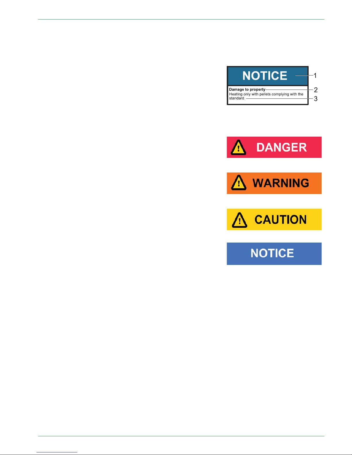
33 Types of safety warning sign
The warning signs use the following symbols and texts.
Types of safety warning sign
1. Risk of injury
2. Consequences of risk
3. Avoiding risk
1. Risk of injury:
Danger - indicates a situation that could lead to death or lifethreatening injury.
Warning - indicates a situation that could lead life-threatening or
serious injury.
Caution - indicates a situation that could lead to injury.
Note - indicates a situation that could lead to property damage.
2. Consequences of risk
Effects and consequences resulting from incorrect operation.
3. Avoiding risk
Observing safety instructions ensures that the heating system is
operated safely
Operating Manual PELLEMATIC® PE(S)(K)(B) 10 — 56
8
System overview
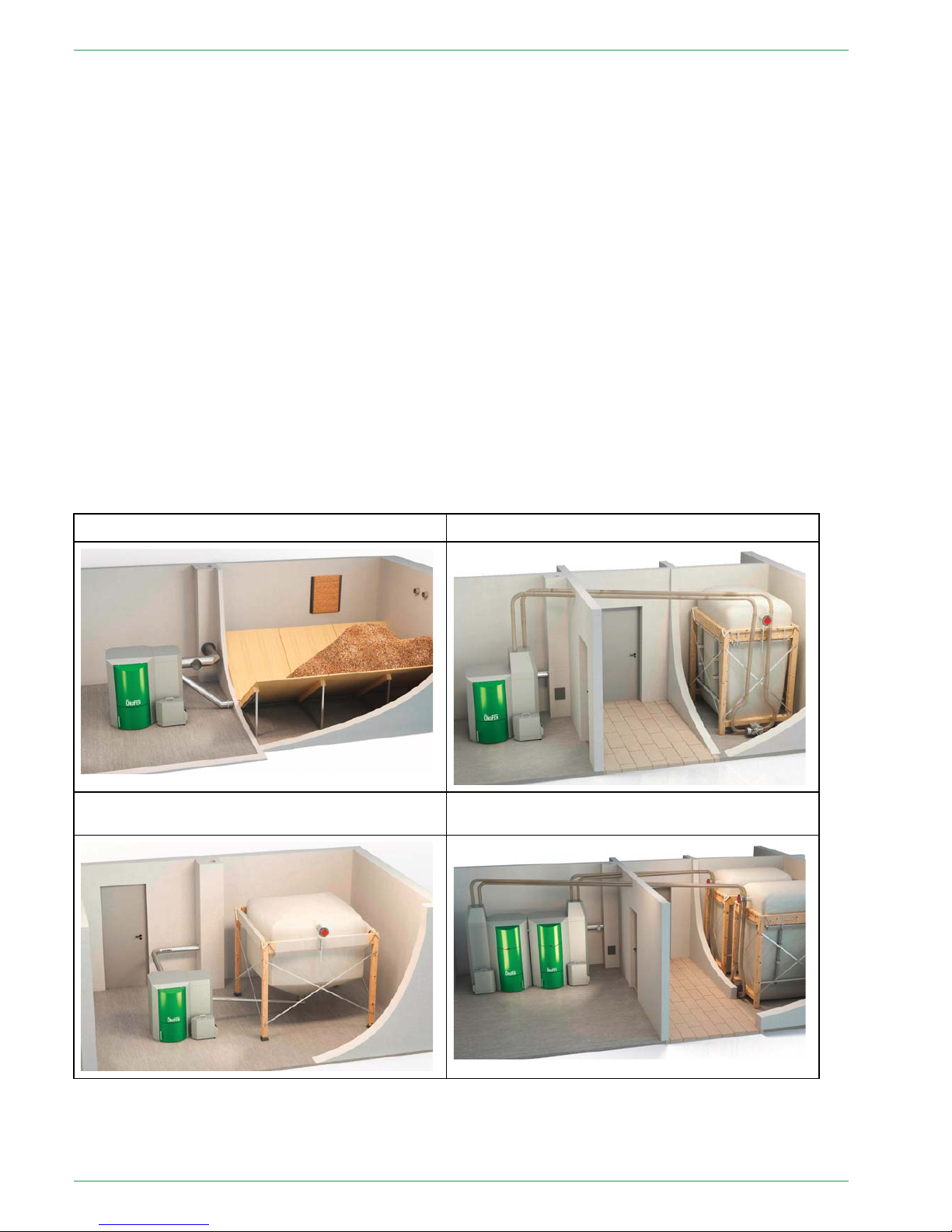
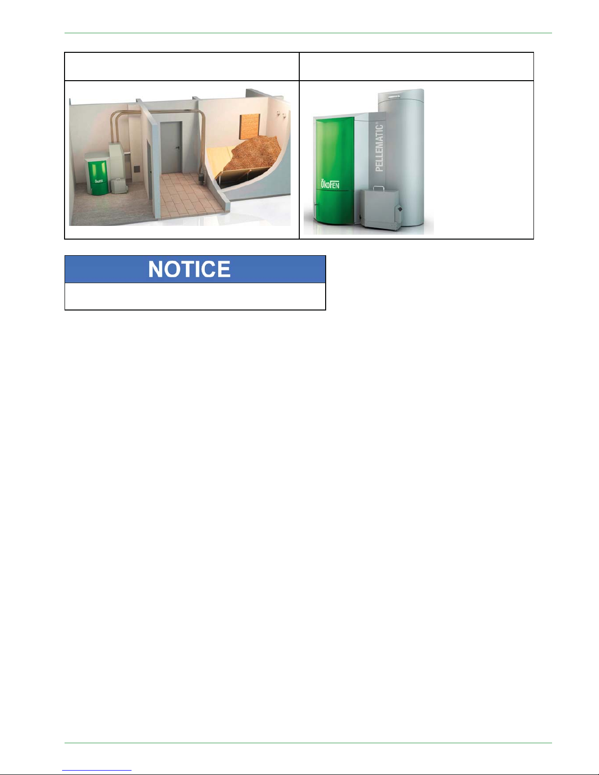
44 System overview
The whole system consists of following components:
ଉ Pellematic boiler:
• PE - Boiler with pellets transport auger as delivery system
• PES - Boiler with vacuum suction system as delivery system
• PEB - Boiler with hopper for hand filling
• PESKA - cascade with up to 4 possible boilers
ଉ Pellet storage room with pellet-delivery system:
• Storage room
• Textile tank
ଉ Possible additional components:
• Domestic hot water
• Accumulator
• Solar thermal panel
• Existing external boiler
Pellematic with storage room and auger delivery Pellematic with textile tank and auger delivery
Pellematic with storage room and vacuum
suction
Pellematic with textile tank and vacuum suction
PE 567 EN 1.1
System overview
9
Pellematic cascade with textile tank and auger
delivery system
Pellematic with hopper for hand filling
There are seperate manuals for all components, which
describe functions and installation in detail.
Operating Manual PELLEMATIC® PE(S)(K)(B) 10 — 56
10
Control system
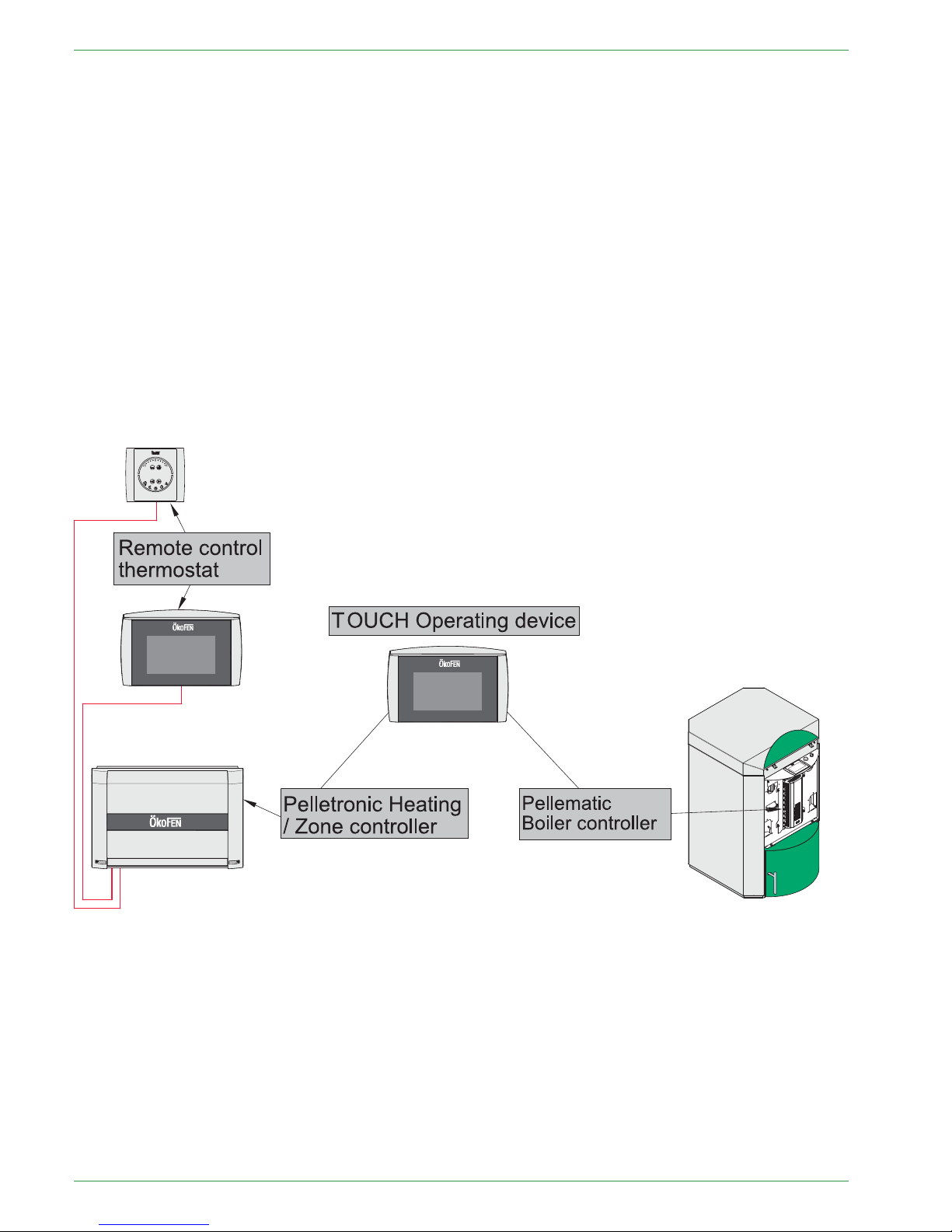
55 Control system
Basically the Controlsystem consists of following components:
• Pellematic boiler controller:
The boiler controller controls all boiler functions (pellet feed system, combustion, deashing, etc.)
• Pelletronic heating controller (max. 3 wall boxes = 6 zones, 3 domestic hot water, 3 accumulators)
The heating controller regulates the whole heat distribution system. (Room temperature, domestic hot
water, time programmes, solar, accumulator management, etc.)
Additionally remote controls can be installed in the system. These can be connected to the heat controller
by a bus-connection.
• Touch Operating Device
The Touch Operating Device is in the boiler. It is connected by a bus-connection with both, heating- and
boiler controller. It serves for:
– visualizing the measuring values
– adjusting the desired values and the time programme on the heating controller.
– adjusting the parameters of the boiler controller
PE 567 EN 1.1

Parameter Adjustments
11
66 Parameter Adjustments
There are two areas in which adjustments can be set:
• User-specific adjustments: e.g. Room temperature, Time program, Domestic hot water temperature,
Domestic hot water time program, Party-function etc.
• System-specific adjustments: e.g. combustion temperature regulation, deashing, ignition parameters,
suction interval, etc.
Ex works, adjustments are basically set, so no further adaption is neccessary.
A detailed description of all important setting options for the end user is to be found in the operating manual
of the End User.
Operating Manual PELLEMATIC® PE(S)(K)(B) 10 — 56

12
The boiler controller
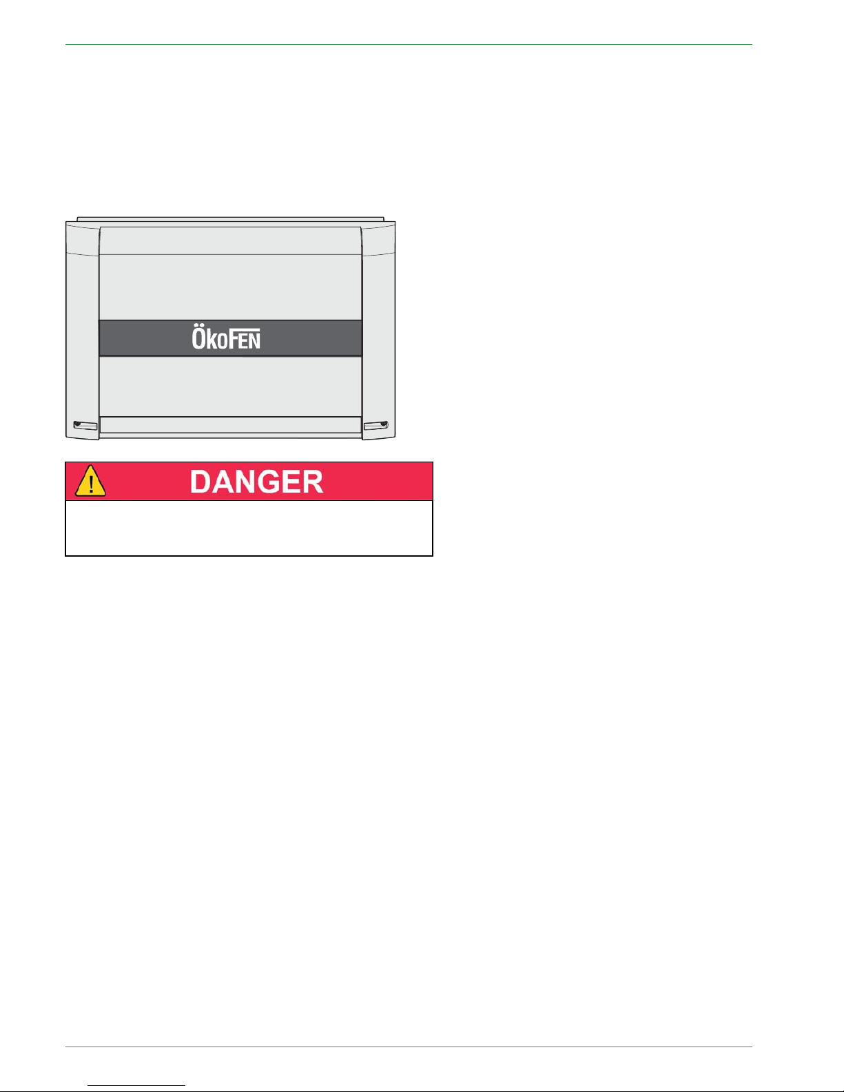
77 The boiler controller
The boiler controller is directly on the Pellematic boiler behind the half-round front cover of the boiler.
It is used to control the combustion process and the fuel-feeding system.
The boiler controller is connected to the touch operating device by a bus-connection.
The Touch allows the owner / operator to see important measured values and Change to "Provides for
adjustment of desired values and parameters of boiler operation. Only authorized installers should adjust
boiler operating parameters."
1 F1: Fuse T10A
2 F2: Fuse T8A
DDaammaaggeeooffpprrooppeerrttyy
Fuses must be replaced only with fuses having the same
current and voltage ratings.
PE 567 EN 1.1

Plugs on the boiler control unit
13
7.1 Plugs on the boiler control unit
The designation of the plugs must correspond with the labeling of plug-in positions.
Designation of plug-in position Voltage Name of sensors, motors and pumps
X1A
3 2 GND 1
24 Volt Operating display
X1B 3 2 GND 1
24 Volt Heating controller (BUS)
X2 5 4
24 Volt Power supply display
R1 46 45
24 Volt Not used
R2 44 43
24 Volt Not used
AF 42 41
24 Volt Not used
KF
89
24 Volt Boiler sensor
UP
234
24 Volt Negative draft measuring
AE2 5 6 7
24 Volt Level detection system
AE1
10 9 8
24 Volt Not used
FRT 12 13
24 Volt Combustion chamber temperature sensor
RGF 14 15
24 Volt Flue gas temperature sensor (optional)
PWM 16 17
24 Volt PWM for speed controlled high-efficiency pump
Analog IN
18 19
24 Volt Not used
BR1 7 8
24 Volt
Burner contact
AK 11 12
24 Volt Existing boiler (optional)
ESAV 32 33 34
24 Volt End switch ash box
DE 1 37 36 35
24 Volt Not used
DE 2 40 39 38
24 Volt Not used
KAPZW 26 25 24
24 Volt Capacitive sensor – hopper
KAPRA 5 4 3
24 Volt Capacitive sensor – burner
BSK 654321
24 Volt Flame return gate
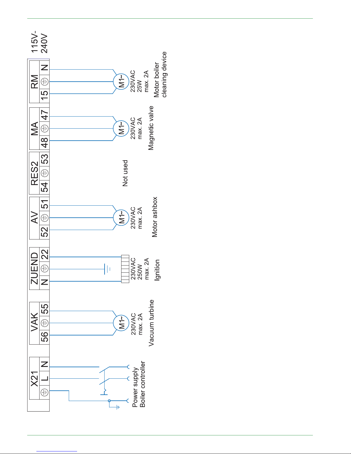
X21 PE L N
230 Volt Power supply
VAK 56 PE 55
230 Volt Vacuum turbine
ZUEND
NPE22
230 Volt
Ignition
AV 52 PE 51
230 Volt Motor ashbox
RES 2 54 PE 53
230 Volt Not used
MA 48 PE 47
230 Volt Magnetic valve (Cleaning nozzle, heat exchanger)
RM 15 PE N
230 Volt Motor boiler cleaning device
SM 19 20
230 Volt Relay fault signal (optional)
SZ 17 PE N
230 Volt Flue gas fan
UW 13 PE N
230 Volt Boiler controlled pump
STB 17 PE 19
230 Volt Safety temperature sensor
NOT 41 43
230 Volt Emergency stop heating
RA1 N PE 14 15 16
230 Volt Fuel transport system
RES1 50 PE 49
230 Volt Motor hopper – PES 36–56 only
ZW
NPE262524
230 Volt Vibration motor
Operating Manual PELLEMATIC® PE(S)(K)(B) 10 — 56

14
Plugs on the boiler control unit
ES 1 2 3 N PE 6
230 Volt
Burner motor
LUFT N PE 11
230 Volt Burner fan
PE 567 EN 1.1

Wiring diagrams
15
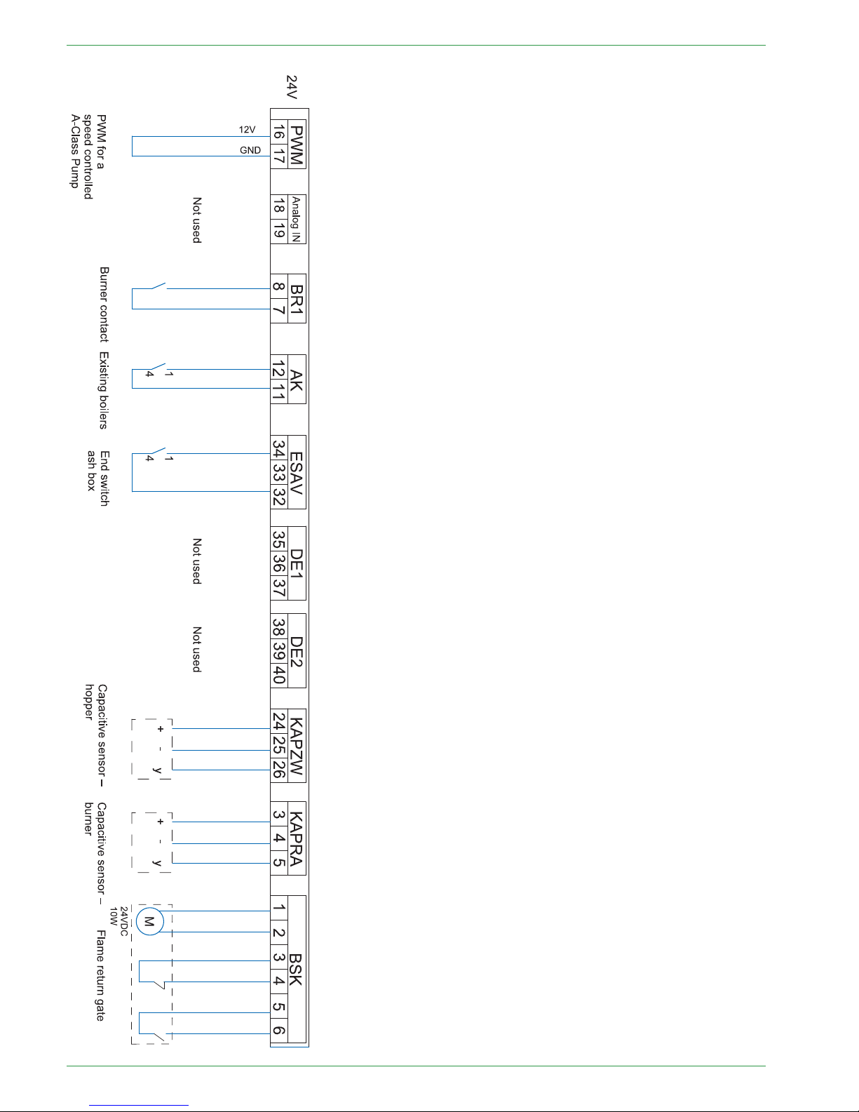
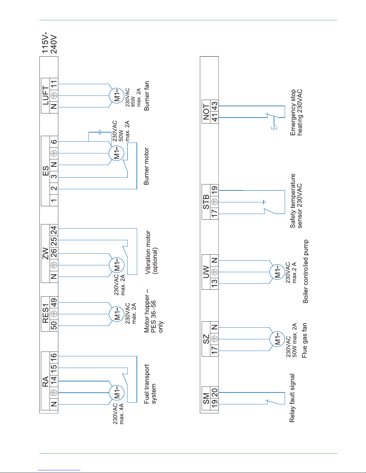
7.2 Wiring diagrams
The wiring diagrams for the boiler control unit provide detailed technical information for certified installers.
Only certified installers or electricians under the direction of a certified installer may connect to the
controller.
RRiisskkooffeelleeccttrriiccsshhoocckk
Only an authorised installer may connect the pellet boiler to the power supply.
Always disconnect / de-energize the power supply before working on the boiler.
Operating Manual PELLEMATIC® PE(S)(K)(B) 10 — 56
16
Wiring diagrams
PE 567 EN 1.1
Wiring diagrams
17
Operating Manual PELLEMATIC® PE(S)(K)(B) 10 — 56
18
Wiring diagrams
PE 567 EN 1.1

LED status boiler controller 19
7.3 LED status boiler controller
Display Description Cause and remedy
red Power supply present
—
red flashing Error condition
no communication possible
Check the software version
Check the bus wiring
Check the address
red / orange flashing
In the bus systems are devices using
the same address
Change the address
orange
Power supply present
Processor runs
No bus communication
Check the software version
Check the bus wiring
Check the address
orange flashing Firmware- update is in progress
—
green flashing Initialization (Firmware boots) If state is unchanged, software must
be checked.
green
Operation
Cyclic communication possible
—
7.4 Cable Routing
Th cable routing and the connection of the motors and sensors is precisely described in the Installation manual .
Operating Manual PELLEMATIC® PE(S)(K)(B) 10 — 56
20
The heating controller
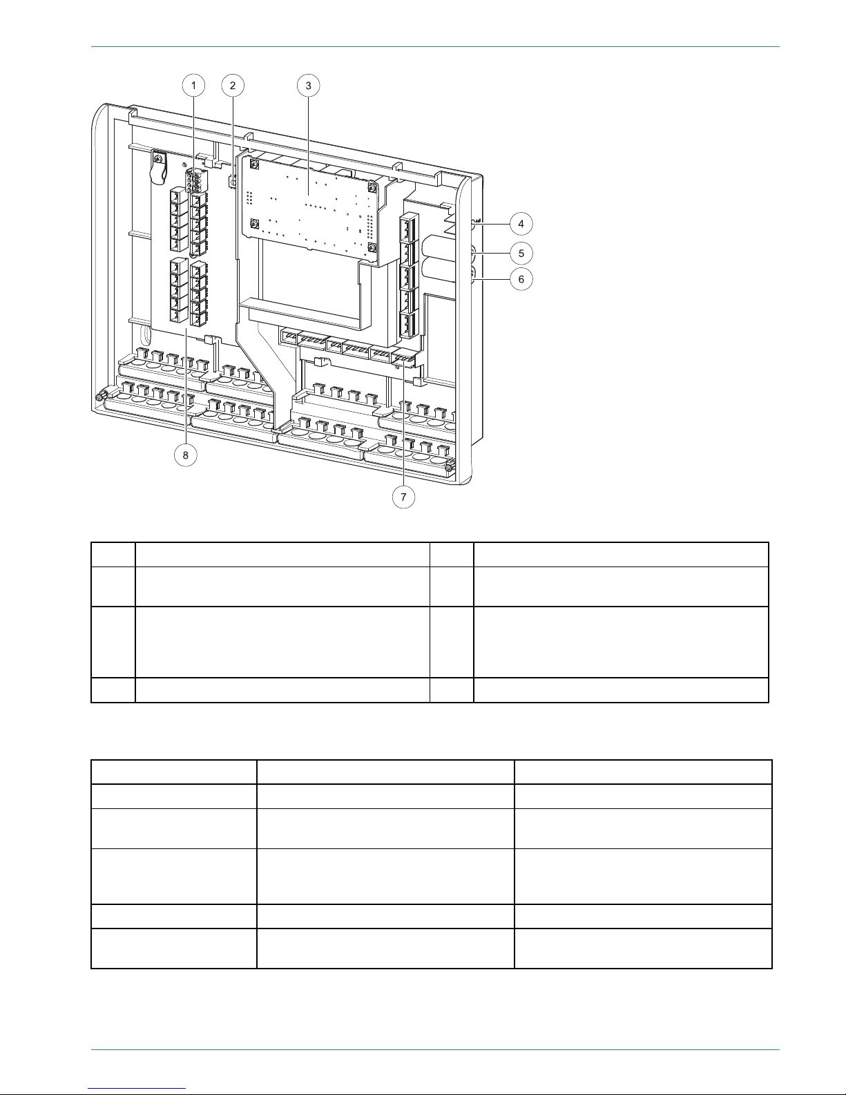
88 The heating controller
The heating controller is in a wall box, which is in most cases installed nearby the heating circuit distributor.
It is used to control the whole heat distribution system for example: domestic hot water, room temperature,
solar system, accumulator, etc
It consists of a casing with an internal circuit board and terminals.
The cover plate of the casing is removable.
EElleeccttrriiccsshhoocckkddaannggeerr
Before opening, make sure that the whole heating
system is powerless.
Note:
The heating controller is limited to 8 amps total current draw. Also, each output is rated at 2 amps max.
Make sure that these values are not exceeded to avoid fuse failure.
PE 567 EN 1.1
LED status heating controller
21
1
Bus connecting terminal RS485 A and B
5
Fuse 6,3 A (fast) for X31 and X33
2
Address switch
6
Fuse 8 A (slow-acting) limits the current
consumption of the heating controller.
3
Slot for an optional power supply
(The power supply is needed when the
burner control CMP 06.2 is used. The power
supply takes over the bus supply.)
7
Low voltage – area (dangerous voltage)
4 Status-LED 8
Extra low voltage (PELV)
8.1 LED status heating controller
Display Description Cause and remedy
red Power supply present
—
red flashing Error condition
no communication possible
Check software version
Check bus wiring
orange
Power supply present
Processor runs
no communication possible
Check bus wiring
green flashing Initialization (Firmware boots)
—
green
Operation
Cyclic communication possible
—
Operating Manual PELLEMATIC® PE(S)(K)(B) 10 — 56

22
Connection plan
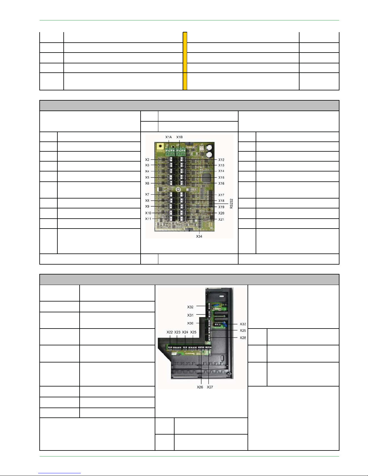
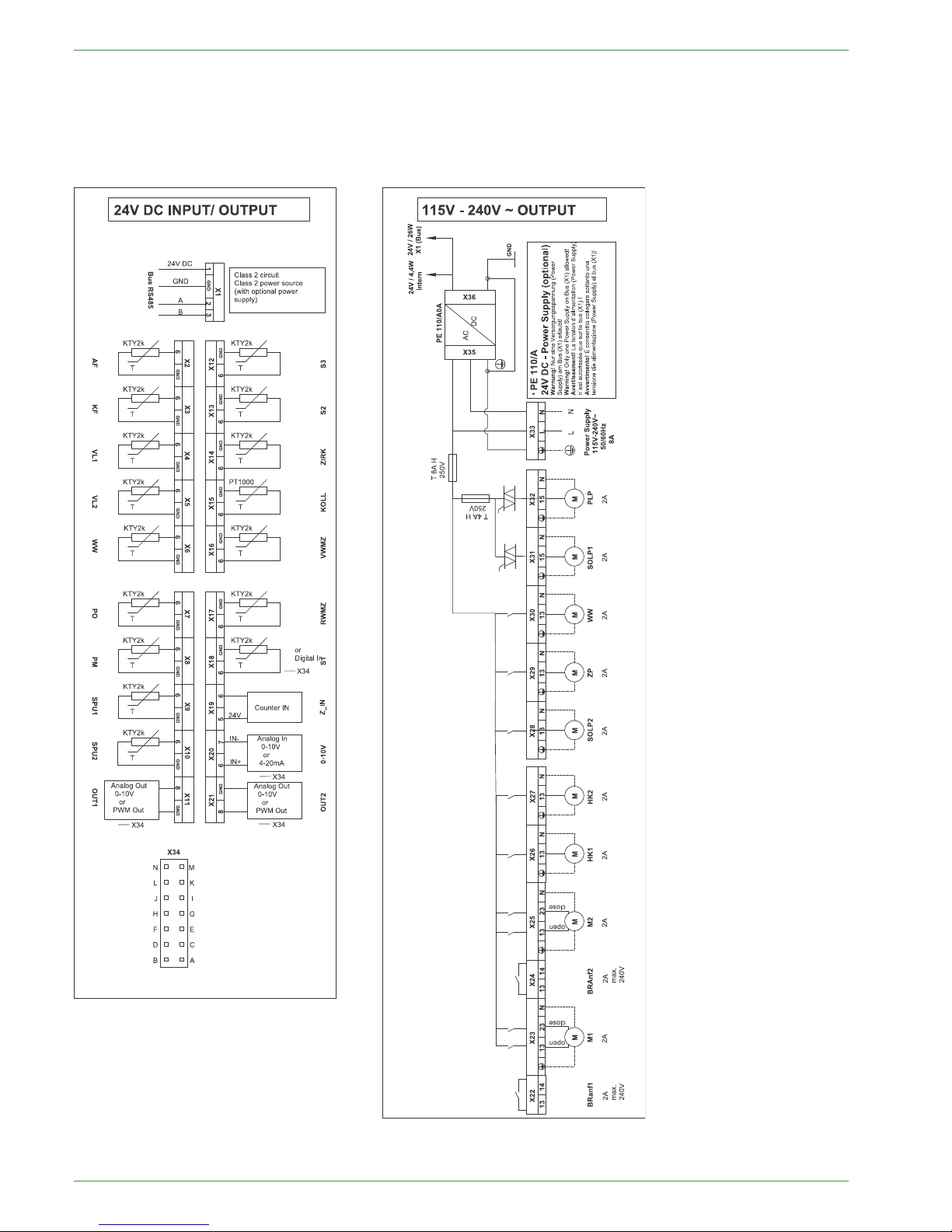
8.2 Connection plan
The Connection plan is a description of all the electrical connections from the Pelletronic heating controller:
Only an authorised installer may install and connect the
heating controller to the power supply.
Isolate the entire heating system from the power supply
before starting work on the heating controller.
Boiler sensor + outside sensor must be connected on
the first heating controller!
Terminals extra-low voltage zone Terminals low voltage zone - 120VAC
X1A Bus wiring – Bus RS485
Burner demand 1 – BRanf 1
X22
X1B Bus wiring – Bus RS485 Mixer HK1 opening – M1
X23 – 13/N
X2
Outdor sensor – AF Mixer HK1 closing – M1
X23 – 23/N
X3
Boiler sensor – KF Burner demand 2 – BRanf 2
(Potencial free contact)
X24
X4
Flow sensor HK1 – VL1
Mixer HK2 opening – M2
X25 – 13/N
X5
Flow sensor HK2 – VL2 Mixer HK2 closing – M2
X25 – 23/N
X6
DHW sensor – WW Heating circuit pump – HK1 X26
X7
AC upper sensor – PO Heating circuit pump – HK2 X27
X8
AC middle sensor – PM Solar pump 2 – Sol P2
X28
X9
AC lower sensor 1 – SPU1
Return pump – Heat main pump – ZP X29
X10
AC lower sensor 2 – SPU2 Domestic hot water – WW
X30
X11
Solar pump 1 A-class Solar pump 1– Sol P1
X31
X12 Reserve – S3
Accumulator pump – PLP
X32
X13 Reserve – S2
Power supply 115V – 240V~
X33
X14 Return sensor – ZIRK
X15
Collector sensor – KOLL
X16
Solar energy Flow – VWMZ
PE 567 EN 1.1
Connection plan
23
X17
Solar energy Return – RWMZ
X18 Reserve – S1
X19
Flow rate 24V – Z_IN
X20 Reserve – 0-10V
X21
Solar pump 2 A-class or Accumulator
pump A-class
Terminals extra-low voltage zone
X1A Bus wiring – Bus RS485
X1B Bus wiring – Bus RS485
X2
Outdor sensor – AF
X12 Reserve – S3
X3
Boiler sensor – KF
X13 Reserve – S2
X4
Flow sensor HK1 – VL1
X14 Return sensor – ZIRK
X5
Flow sensor HK2 – VL2
X15
Collector sensor – KOLL
X6
DHW sensor – WW
X16
Solar energy Flow – VWMZ
X7
AC upper sensor – PO
X17
Solar energy Return–
RWMZ
X8
AC middle sensor – PM
X18 Reserve – S1
X9
AC lower sensor 1 – SPU1
X19
Flow rate 24V – Z_IN
X10
AC lower sensor 2 – SPU2
X20 Reserve – 0-10V
X11
Solar pump 1 A-class
X21
Solar pump 2 A-class or Accumulator pump A-class
X34 Jumper
Terminals low voltage zone - 120VAC
X32
Accumulator pump –
PLP
X31
Solar pump 1– Sol P1
X30
Domestic hot water –
WW
X25 – 23/N
Mixer HK2 closing – M2
X33
Power supply 115V –
240V~
X25 – 13/N
Mixer HK2 opening – M2 X29
Return pump – Heat
main pump – ZP
X24
Burner demand 2 –
BRanf 2
(Potencial free contact)
X28
Solar pump 2 – Sol P2
X23 – 23/N
Mixer HK1 closing – M1
X23 – 13/N
Mixer HK1 opening – M1
X22
Burner demand – BRanf 1
X26 Heating circuit pump –
HK1
X27 Heating circuit pump –
HK2
Operating Manual PELLEMATIC® PE(S)(K)(B) 10 — 56
24
Connection plan
Electrical wiring diagrams heating controller
The wiring diagrams are also located on the inside of the cover of the heating controller.
Be aware of the instructions and diagrams illustrated there.
PE 567 EN 1.1

Jumper X34 for analog voltage outputs X11 (OUT1) and X21 (OUT2)
25
88..22..11JJuummppeerrXX3344ffoorraannaallooggvvoollttaaggeeoouuttppuuttssXX1111((OOUUTT11))aannddXX2211((OOUUTT22))
The different types of high-efficiency pumps: Analog pumps with 0-10 V control and PWM pumps with 24V.
For each type of pump you have to adjust the signal at the heating controller.
The plug connector X34 is for the Jumper-settings. Use a jumper with a grid dimension of 1 inch. The terminals X11 and X21 can receive or export a different signal depending on the jumper position.
Note:
When using PWM-pumps for a voltage up to 15V, adapter-cables must be connected at the slots X11 and
X12.
These cables limit the output voltage from 24V to 15V.
Jumpersettings X34:
The male connector X34 serves for jumper-adjustments. Please use jumper with a contact spacing of 1 inch
(included in delivery of heating controller)
High-efficiency
pump with external
control function
Terminal Designation Function Plug
connector
Position
Solar pump 1
X11 Out 1 PWM Out
Analog Out
0-10V
A-B and C-D
A-B and C-D
0
X
Solar pump 2
(or accumulator
pump)
X21 Out 2 PWM Out
Analog Out
0-10V
E-F and G-H
E-F and G-H
0
X
0.... Jumper is not set, pins open.
X.... Jumper is set, pins closed.
8.3 Rules of wiring for micronetwork with 1,2 or more heating
controllers
The boiler controller suplies the touch operating device and up to two remote controls.
• The order of devices in the bus-wiring is free. The station-numbers for the heating controller and the digital
remote controls have to be assigned uninterrupted.
• The number of heating controllers is independent from the numbers of the digital remote controls and independent from the numbers of boiler controllers.
•Adouble allocation is not acceptable.
• The maximum limit of bus-participiants is 16.
• The maximum length of a bus-cable is 200 metres.
• The maximum cable-length depends on:
– A solid point-to-point topology allows the fullmax. length.
–Astar-topology does not allow the max. length.
– We recommend a twisted-pair cable, especially for long cables (e.g. in buildings) and if the cable runs paralell to other cables.
– Correct bus-connection resistance, which is always existing on boiler operating device.
For long cables or communication problems occur, a additional resistor with 120 Ohm has to be clamped
between wire A and B at the last bus-participant.
When controlling a cascade-system, a bridge must be
installed at boiler controller port X2.
Operating Manual PELLEMATIC® PE(S)(K)(B) 10 — 56
26
Wiring diagrams
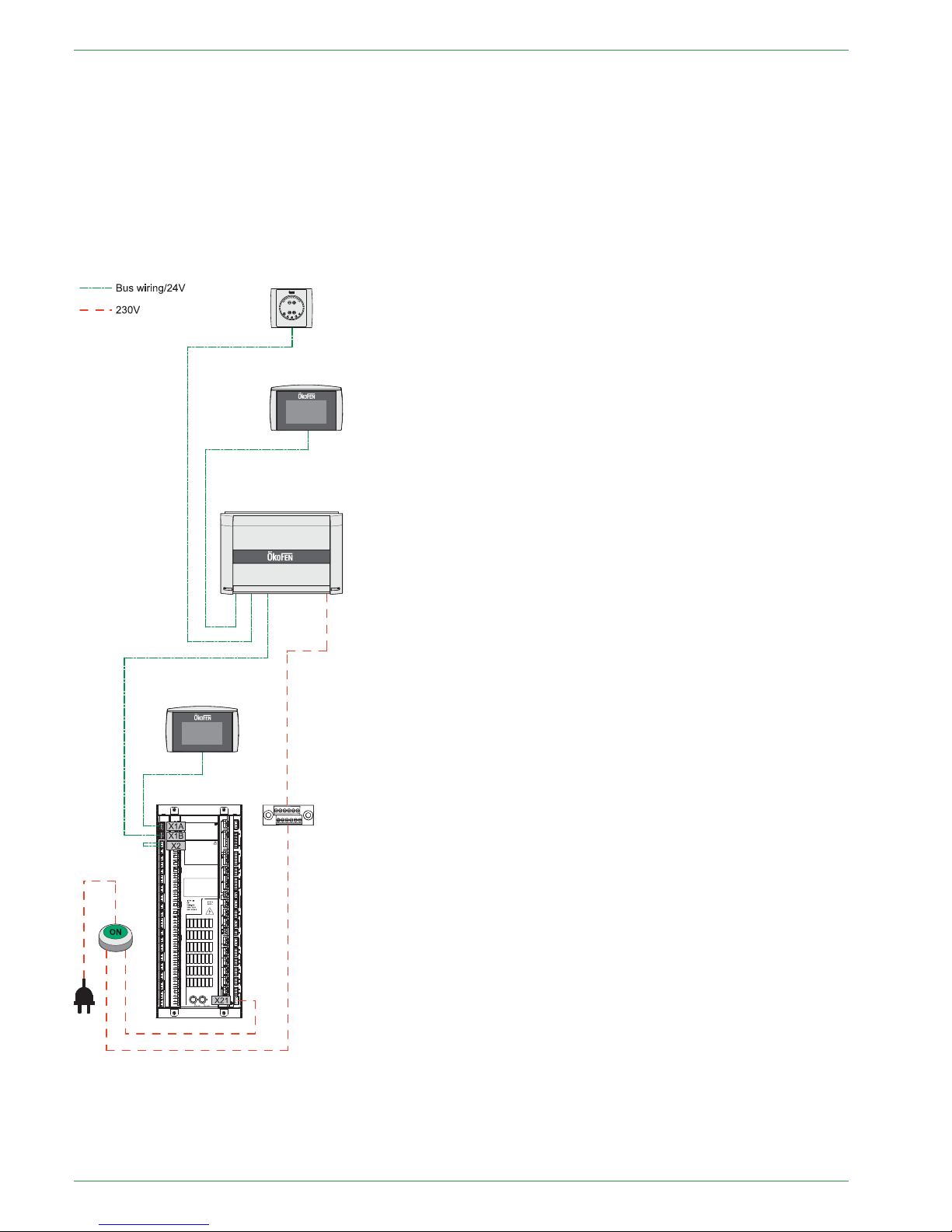
8.4 Wiring diagrams
Wiring diagram with:
• 1x Boiler controller FA
• 1x Heating controller Pelletronic
• 1x Touch operating device (Master)
• 1x Touch remote control (Slave)
• 1x Remote controll with LED
Note:
You find more detailed information about wiring in chapter 8.3 Rules of wiring for micronetwork with 1,2
or more heating controllers, page 25
PE 567 EN 1.1
Wiring diagrams
27
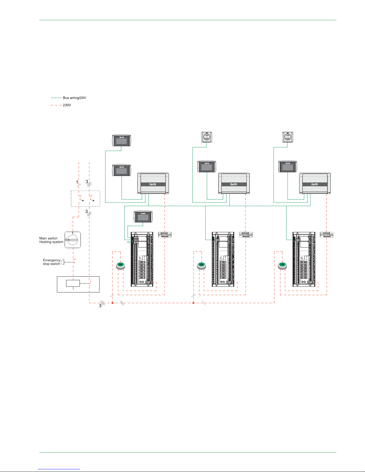
Wiring diagram with:
• 3x Boiler controller FA
• 3x Heating controller Pelletronic
• 1x Touch operating device (Master)
• 4x Touch remote control (Slave)
• 2x remote controll with LED
Note:
You find more detailed information about wiring in chapter 8.3 Rules of wiring for micronetwork with 1,2
or more heating controllers, page 25
Operating Manual PELLEMATIC® PE(S)(K)(B) 10 — 56
28
Assembly and disassembly of the heating controller circuit board
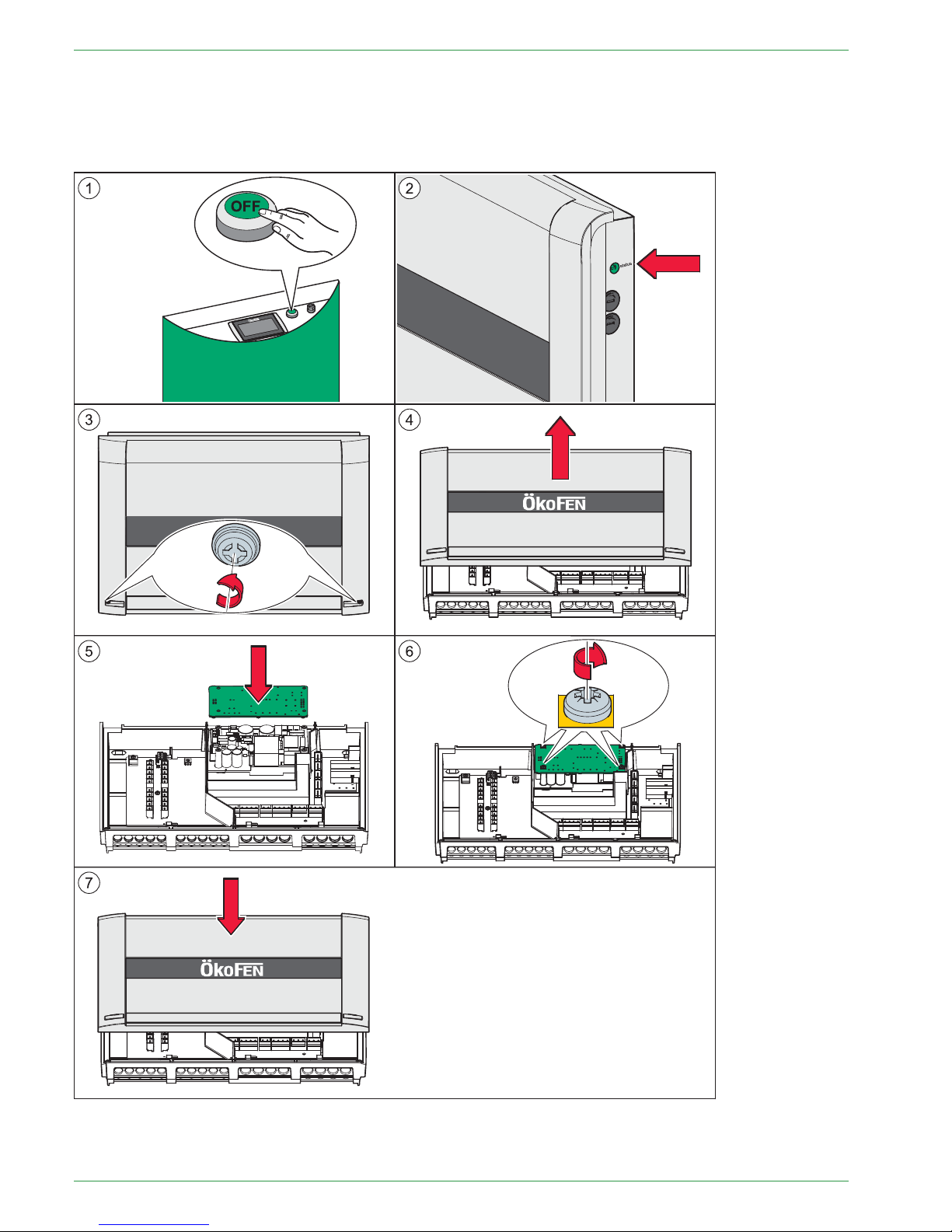
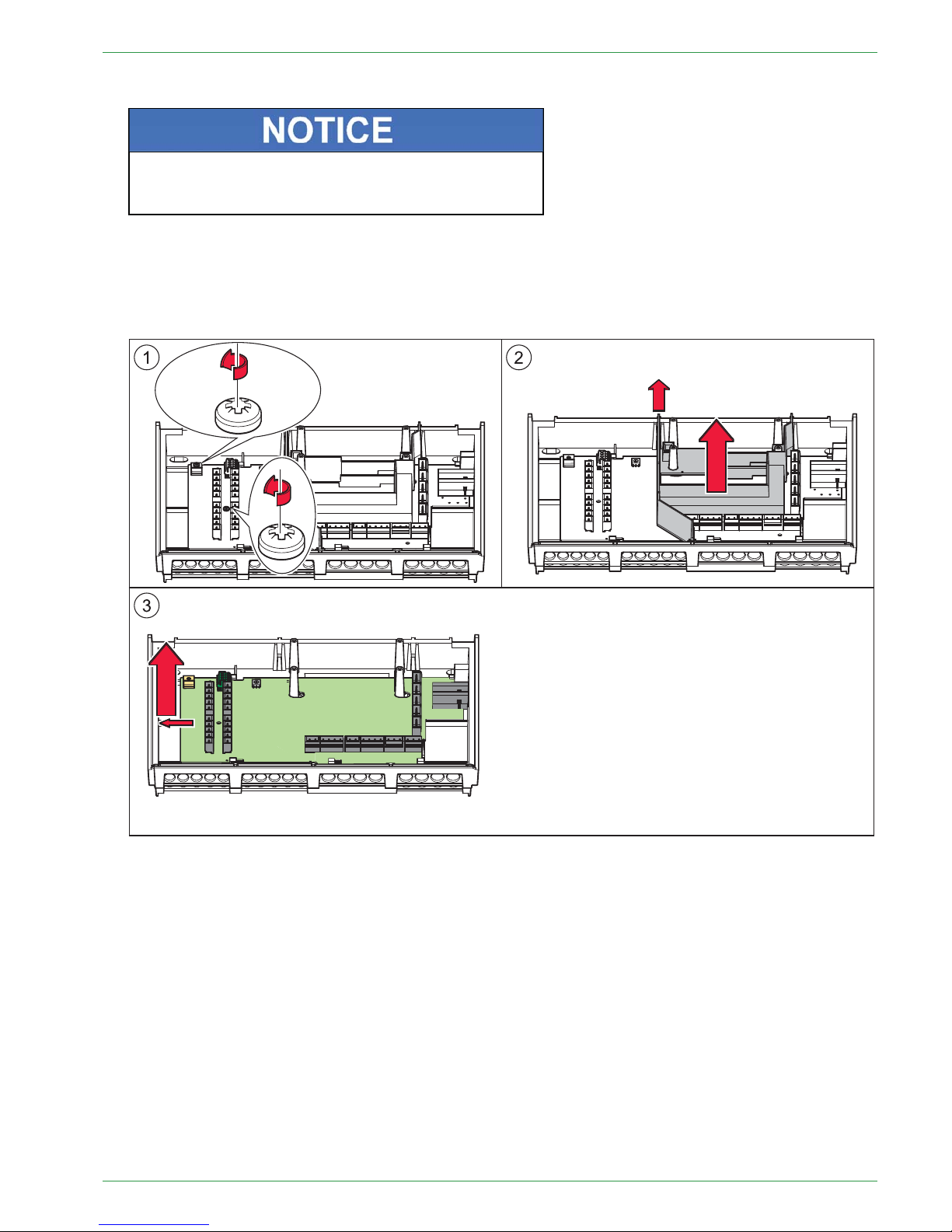
8.5 Assembly and disassembly of the heating controller circuit
board
You can take off the circuit board of the heating controller, without filtering out the inputs and outputs.
Note:
Image 2: Control with the status of the LED that the heating controller is electroless.
PE 567 EN 1.1
Assembly and disassembly of the heating controller circuit board
29
1. Make the complete heating system powerless.
EElleeccttrroossttaattiiccddiisscchhaarrggeeddaammaaggee
Before starting work, touch a grounded object to avoid
damage of circuit board by electrostatic charging.
2. Open the cover plate of the heating controller.
3. Disconnect all plugs from the circuit board. Leave the plugs with the wiring in the casing.
4. Disassembly from the power supply (optional)
5. Disassembly the circuit board from the heating controller.
6. The installation of a new circuit board occurs in reverse order.
Operating Manual PELLEMATIC® PE(S)(K)(B) 10 — 56

30
Cable specification Pelletronic Touch
8.6 Cable specification Pelletronic Touch
Power supply
K02
X33 YML-J 3x1
x
OUTPUTS see on wiring diagram on the front side
Function – Shortcut
Cable
Pin I/O BOX
Cable type Section
Max
Ampere
Burner contact 1 – BRanf 1
K 03 X22
YML-J
3x0.75 2A
Mixer HK1 OPEN – M1 K 12
X23 – 13/N
YML-J
3x0.75 2A
Mixer HK1 CLOSED – M1 K 12
X23 – 23/N
YML-J
3x0.75 2A
Burner contact 2 – BRanf 2
(Potencial free contact)
K 30 X24
YML-J
3x0.75 2A
Mixer HK2 OPEN – M2 K 13
X25 – 13/N
YML-J
3x0.75 2A
Mixer HK2 CLOSED – M2
K13
X25 – 23/N
YML-J
3x0.75 2A
Heating circuit pump – HK1 K 14 X26
YML-J
3x0.75 2A
Heating circuit pump – HK2 K 15 X27
YML-J
3x0.75 2A
Solar pump 1 – Sol P1
K 16 X31 YML-J 3x0.75 2A
Return pump – Heat main pump –ZPK 29 X29
YML-J
3x0.75 2A
Domestic hot water pump – WW
K 21 X30
YML-J
3x0.75 2A
Solar pump 2 – Sol P2
K 23 X28 YML-J
3x0.75 2A
Accumulator pump – PLP
K 05 X32 YML-J 3x0.75 2A
Bus wiring – Bus RS485 K 01 X1A YSLCY–0Z 4x0.75
x
Bus wiring – Bus RS485 X1B YSLCY–0Z 4x0.75
x
Solar high-efficiency pump 1
K 28 X11 YML
2x0.75
x
Solar high-efficiency pump 2 or
Accumulator high-efficiency
pump
K 71 X21
YML
2x0.75
x
INPUTS see on wiring diagram on the front side
Function – Shortcut
Cable
Pin I/O BOX
Cable type Section
Max
Ampere
Outdor sensor – AF
K 09 X2 YML 2x0.75
KTY 2k
Boiler sensor – KF
K04
X3 YML
2x0.75
KTY 2k
Flow sensor HK1 – VL1
K 10 X4 YML 2x0.75
KTY 2k
Flow sensor HK2 – VL2
K 11 X5 YML
2x0.75
KTY 2k
DHW sensor – WW
K19 X6
YML
2x0.75
KTY 2k
AC upper sensor (TPO) – PO K 18
X7 YML
2x0.75
KTY 2k
AC middle sensor (TPM) – PM
K 17 X8 YML
2x0.75
KTY 2k
AC lower sensor 1 – SPU1
K20 X9
YML
2x0.75
KTY 2k
AC lower sensor 2 – SPU2
K 22 X10
YML
2x0.75
KTY 2k
Reserve sensor – S3 X12 YML
2x0.75
KTY 2k
Sensor existing boiler – S2
X13 YML
2x0.75
KTY 2k
Sensor return pump – ZIRK K 29 X14 YML 2x0.75
KTY 2k
PE 567 EN 1.1

Sensor values 31
Collector sensor – KOLL
K 08 X15 YML 2x0.75 PT 1000
Solar energy Flow – VWMZ
K 25 X16
YML
2x0.75
KTY 2k
Solar energy Return – RWMZ
K 26 X17 YML 2x0.75
KTY 2k
Sensor Reserve – S1 X18
YML
2x0.75
KTY 2k/Dig
I
Flow rate 24V – Z_IN
X19
YML
2x0.75
x
Reserve – 0-10V X20
YML-J 3x1
x
8.7 Sensor values
Values of resistance and thermic voltage of the different sensores can be found in the following table:
Temperature [°C]
Resistance temperature sensor [] thermical voltage [9]
PT 1000
(collector sensor)
KTY
(heating sensor)
NiCr Ni
(combustion
chamber sensor)
-20 922 1396
-777
-15 941 1431 -588
-10 961 1499 -392
-5
980 1562 -196
0 1000 1630 0
5
1020 1700 -199
10 1039 1772 397
15 1058 1846 596
20 1078 1922 798
25 1097 2000 997
30 1117 2080 1203
40 1155 2245 1611
50 1194 2418 2022
60 1232 2599 2436
70 1271 2788 2850
80 1309 2984 3266
90 1347 3188 3681
100 1385 3400 4095
Operating Manual PELLEMATIC® PE(S)(K)(B) 10 — 56

32
Hydraulic connecting diagrams
8.8 Hydraulic connecting diagrams
88..88..11HHyyddrraauulliiccccoonnnneeccttiinnggddiiaaggrraammssPPeelllleettrroonniiccTToouucchh
88..88..11..11DDiiaaggrraamm11
1 Boiler Pellematic – 1 Accumulator Pellaqua – 2 Heating circuits – 1 Solar circuit
88..88..11..22DDiiaaggrraamm22
1 Boiler Pellematic – 1 DHW Accumulator – 2 Heating circuits – 1 Solar circuit
PE 567 EN 1.1

Diagram 3
33
88..88..11..33DDiiaaggrraamm33
1 Boiler Pellematic – 1 Accumulator Pellaqua – 2 Heating circuits – 1 Fresh water module – 1 Solar circuit
Pellematic
88..88..11..44DDiiaaggrraamm44
1 Boiler Pellematic – 2 Accumulators Pellaqua – 2 Fresh water module – 4 Heating circuits – 1 Solar circuit
Pellematic
Operating Manual PELLEMATIC® PE(S)(K)(B) 10 — 56

34
Diagram 5
88..88..11..55DDiiaaggrraamm55
1 Boiler Pellematic – 1 Accumulator Pellaqua – 1 Fresh water module – 4 Heating circuits – 1 Solar circuit – 1
DHW Accumulator
Solar plant
Pellematic
X4
X26
X23
X5
X27
X25
X30
X6
Outdoor sensor
TI
TI
TI
TI
X4
X26
X23
X5
X27
X25
X31
X15
X6
X7
X8
X9
Freshwater
module
BUS
Feeding controller
BUS
Power 230V
X2
UW
TI
X29
Power 230V
PWM
88..88..11..66DDiiaaggrraamm66
1 Boiler Pellematic – 1 Accumulator Pellaqua – 1 DHW Accumulator – 2 Heating circuits – 2 Solar circuits
1
2
Solar plant
Pellematic
X2
TI
TI
TI
TI
TI
TI
X4
X26
X23
X5
X27
X25
X15
X6
X16
X17
X19
X28
X31
X9
X10
Outdoor sensor
X7
X8
Power 230V
BUS
Feeding controller
TI
UW
PWM
PE 567 EN 1.1

Diagram 7
35
88..88..11..77DDiiaaggrraamm77
1 Boiler Pellematic – 1 Accumulator Pellaqua – 2 Heating circuits – 1 Layer charge modul
1
2
Solar plant
Pellematic
Outdoor sensor
X2
Power 230V
X6
X7
X8
X10
X4
X5
X9
X29
X28
X15
X31
Power 230V
BUS
Feeding controller
88..88..11..88DDiiaaggrraamm88
1 Boiler Pellematic – 1 Accumulator Pellaqua – 2 Heating circuits – Solar layer device
1
2
Solar plant
Pellematic
Outdoor sensor
X2
Power 230V
X6
X7
X8
X10
X4
X5
X9
X15
X29
X28
X31
X16
X17
X19
Power 230V
BUS
Feeding
controller
Operating Manual PELLEMATIC® PE(S)(K)(B) 10 — 56

36
Diagram 9
88..88..11..99DDiiaaggrraamm99
1 Boiler Pellematic – 1 Accumulator Pellaqua – 2 Heating circuits – 1 Heat main pump
1
2
3
4
Pellematic
X2
Power 230V
X6
X7
X8
X4
X5
TI
TI
TI
TI
X4
X26
X23
X5
X27
X25
X29
BUS
Stromvers.
230V
Outdoor
sensor
Feeding - controller
88..88..11..1100DDiiaaggrraamm1100
2 Boilers Pellematic – 1 Hydraulic separator – 4 Heating circuits
1
2
3
4
X2
Hydraulic separator
Pellematic
BUS
Pellematic
Power 230V
BUS
TI
TI
TI
TI
X4
X26
X23
X5
X27
X25
TI
TI
TI
TI
X4
X26
X23
X5
X27
X25
BUS
BUS
Power 230V
X3
Outdoor sensor
TI
TI
UW
PWM
TI
TI
UW
PWM
Power 230V
Power 230V
PE 567 EN 1.1

Diagram 11
37
88..88..11..1111DDiiaaggrraamm1111
2 Boilers Pellematic – 1 Accumulator Pellaqua – 1 Fresh water module – 2 Heating circuits
1
2
X2
TI
Pellematic
Power 230V
Pellematic
Power 230V
BUS
Power 230V
Fresh water
module
TI
TI
TI
TI
X4
X26
X23
X5
X27
X25
Outdoor sensor
X6
X7
X8
TI
TI
TI
UW
PWM
UW
PWM
88..88..11..1122DDiiaaggrraamm1122
4 Boilers Pellematic – 1 Accumulator Pellaqua – 2 Heating circuits
1
2
X2
Pellematic
Pellematic
BUS
Power 230V
X7
X8
TI
TI
TI
TI
X4
X26
X23
X5
X27
X25
Pellematic
Pellematic
BUS
BUS
Outdoor sensor
TI
TI
UW
PWM
TI
TI
UW
PWM
TI
TI
UW
PWM
TI
TI
UW
PWM
Power 230V
Power 230V
Power 230V
Power 230V
Operating Manual PELLEMATIC® PE(S)(K)(B) 10 — 56

38
Diagram 13
88..88..11..1133DDiiaaggrraamm1133
1 Boiler Pellematic – 1 Wood boiler – 1 Accumulator Pellaqua – 1 DHW Accumulator – 2 Heating circuits – 1 Solar
circuit
1
2
Solar plant
Termix
valve
TI
TI
TI
TI
Pellematic
X13
TI
TI
TI
TI
X4
X26
X23
X5
X27
X25
X9
X6
X30
X15
X31
X28
X24*
* Manual
Note:
X24 is a potential free contact to trigger an external heating boiler.
X7
X2
outdoor sensor
X8
X10
Power
230V
BUS
Feeding- controller
TI
TI
UW
PWM
PE 567 EN 1.1

Diagram 14
39
88..88..11..1144DDiiaaggrraamm1144
1 Boiler Pellematic – 1 Wood boiler – 1 DHW Accumulator – 2 Heating circuits – 1 Solar circuit
KW
1
2
Solar plant
Pellematic
Power
230V
BUS
TI
TI
TI
TI
TI
TI
X13
TI
TI
TI
TI
X4
X26
X23
X5
X27
X25
X30
X6
X9
X31
X15
X2
X24*
* Manual
Outdoor sensor
TE
X24*
Feeding - controller
Note:
If the value of the boiler sensor from the existing boiler (X13 S2) rises above the switch temperature, the
Pellematic is switched off.
After reaching the adjusted pump enabling temperature, the diverter valve (X24) switches. Energy can
be taken from the existing boiler.
X24 is a potential–free contact for regulating an external boiler.
Operating Manual PELLEMATIC® PE(S)(K)(B) 10 — 56

40
Diagram 15
88..88..11..1155DDiiaaggrraamm1155
1 Boiler Pellematic – 1 Accumulator Pellaqua – Circulation on Accumulator Pellaqua – Yield Measuring Solar
1
2
Pellematic
X2
X6
X7
X8
X9
X4
X5
X15
Outdoor sensor
X29
X14
X17
X16
X19
BUS
Power
230V
Feeding - controller
* Manual
Note:
If the value on the boiler sensor from the existing boiler (X13 S2) rise above the switch temperature the pellematic will be switched off.
After reaching the adjusted pump on temperature, the diverter valve (X24), so that the energy can be taken from the existing boiler.
PE 567 EN 1.1

The Touch operating device
41
99 The Touch operating device
The Touch operating device is mounted on the control board of Pellematic.
The 4.7" color display is surrounded by a foil design with logo.
With finger pressure you make settings on the Touch operating device.
1
User control unit Operates the boiler controller and the heating controller.
2
Main switch Switches off the heating system (both poles) including the power supply
to the control panel.
3
Safety
temperature sensor
Switches the heating system off if the boiler temperature reaches 95°C.
The heating controller remains active.
The touch panel is dark during in standby mode.
As soon as you touch the surface of the touch, light turns on and displays the opening window.
1
Measuring values (adjustable)
2
Date
3 Hour
4
The icon house takes to the main menu
5
Weather
Note:
If there is a malfunction, the
corresponding fault message is displayed
at this point instead of the weather icon
6
Favorite 1 (adjustable)
7
Favorite 2 (adjustable)
8
Favorite 3 (adjustable)
Operating Manual PELLEMATIC® PE(S)(K)(B) 10 — 56

42
The Touch operating device
Favorit is in the menu General.
With this function you can display most
commonly used menus in the start menu. This
enables you a direct access.
Select 1–3 menu items that should be displayed
as a favorite in the Start menu.
PE 567 EN 1.1

User controls and their function
43
9.1 User controls and their function
1. Navigation-icons
Iconview
If you touch an icon, the icon turns green. The green shows that you are currently on this
icon. You get to the enabled menu item .
The yellow house enters you directly to the main menu.
The horizontal arrow leads you one step back.
With the blue down arrow you get to additional lines of information on this item. (Down scroll down).
With the blue up arrow you get to additional lines of information on this item. (Top of page scroll up)
You get to the respective menu item.
You get to the settings of the parameter. You come either to a numeric keypad, a
time / date block or the text selection.
Operating Manual PELLEMATIC® PE(S)(K)(B) 10 — 56

44
User controls and their function
2. Numeric keyboard
a. Name of parameter
b. Value of parameter with unit
c. Min/max value – Values outside this ran-
ge are not accepted.
d. Delete input of numbers – per contact
you delete one place.
e. Cancel – You return to the menu item. In-
put of a new value was not accepted.
The original value is.
f. Help function – inactive
g. Confirm
h. Numeric keyboard – used to enter values
within the min - max range.
3. Time and date block
a. Adjustable time or date
b. Cancel
c. Help function – inactive
d. Confirm
With the Plus Minus block you change
numbers.
4. Text selection
a. Name of parameter
b. Status texts
The number of status texts depends of
the parameter.
Choose a status text. The setup menu closes
automatically and the chosen status text is
displayed in the menu.
Note:
Although a scroll down menu is open, the navigation icons, menu items and parameters behind are active
and by touching them it takes you directly there .
PE 567 EN 1.1

Main Menu 45
9.2 Main Menu
In the Main menu you see all submenus. By finger pressure on an icon you reach the respective submenu.
A detailed description of the single meus is to be
found in the Manual for End Users in the chapter
Startup procedure.
Operating Manual PELLEMATIC® PE(S)(K)(B) 10 — 56

46
Replacing a Touch operating device
9.3 Replacing a Touch operating device
Exchange the integrated operating device (in the control panel) as follows:
EElleeccttrriiccsshhoocckk
Switch off the system when working on the boiler.
BBrreeaakkddoowwnnTToouucchhooppeerraattiinnggddeevviiccee
Before you press out the Touch operating device, you
must unplug all cables from the operating device.
While pressing out the operating device you have to
counter the top with the palm, so that the operating device does not pop out and falls to ground.
If the new operating device has a different software
state, an update has to be done. All Bus-connected
components have to have the same software-state.
PE 567 EN 1.1

Backside of the Touch operating device
47
9.4 Backside of the Touch operating device
1 Bus connection
•1ڃ +24V
• GND ڃ GND
•2ڃ A
•3ڃ B
2
Ethernet port
3 USB-port USB1
4 USB-port USB0
Operating Manual PELLEMATIC® PE(S)(K)(B) 10 — 56

48
Calibration
9.5 Calibration
Execute a decalibration as follows:
1. Switch off the whole heating system 4. After a few seconds of waiting time the following
mask appears on the Touch operating device:
2. Press by using a finger on the Touch operating
device.
5. Now press the crosshairs in the row they appearing concentric.
Use a pen or similar for a more precise adjustment.
3. Keep your finger pressed and switch the boiler on
again.
PPrrooppeerrttyyddaammaaggee
Watch for a careful way of dealing with the touch
surface!
DDeeccaalliibbrraattiioonn
Avoid the placing of items on the touch operating
device!
PE 567 EN 1.1

Default values and settings
49
1100 Default values and settings
Customer
Default
System
Boiler 1 Boiler 2 Boiler 3 Boiler 4
Operating mode
Operating mode
Auto
Ignition
Burner Auger Run Time 70 zs
Rest time 20 zs
Fan
100 %
Flue Gas Fan
100 %
Temp Hysteresis Softstart
40 K
Heating Full Power
Brennstoffkorrektur
0
Min Abgastemp.
50 °C
Run on
Speed Flue Gas Fan
100 %
Flue Gas Fan Run On Time
1800 sec
FRT + KT Flue gas fan Off
30 K
Cleaning
Mode Ashbox
Run time min 80 min
Delivery Duration
3 min
Boiler run on time 6 h
Boiler cleaning
Cleaning/Filling
20:00
Cleaning 2
8:00
Run time min
12 h
Cleaning time
120 sec
Negative Draft
Mode
ON
Malfunction time
60 sec
Set Value ++
0EH
Minimum ++ 0 EH
Wash ++
0EH
PID Controller - Amplify
30 %
PID Conttroller - Time Integral
Action
130 sec
PID Controller - Time Differential
Action
20 zs
FRT Control
Operating Manual PELLEMATIC® PE(S)(K)(B) 10 — 56

50
Default values and settings
Mode
ON
Temperature min 120 °C
Set Value ++
0K
Limit above
30 %
Limit below
80 %
PID Controller - Amplify
4%
PID Conttroller - Time Integral
Action
200 sec
PID Controller - Time Differential
Action
2zs
Pellet level
Mode Off
Threshold level 400 kg
Correction value 0 kg
Boiler Controlled Pump
On Temp 60 °C
Depends on Require
On
Pump type
Standard
Switch Off Hyst
3K
Run On Time 15 min
Control range
5K
Vacuum turbine
Filling
19:00
Tact RA Motor 55 sec
Pause RA Motor 5 sec
Suction intervall
180 min
Magnetventil
Mode
On
Min runtime
5h
Washing time
60 sec
Settings
Control Temperature
70 °C
Switch Off Temp
76 °C
Malfunction mode
On / Off
Hand filling hopper Off
Capacitive sensor RA -active
Off
Capacitive sensor ZW -active
Off
Switch on hyst
10 K
Output SM
Standard
Input AK
Standard
Outputs
PE 567 EN 1.1

Default values and settings
51
Vacuum turbine - Threshold
current Min
0mA
Vacuum turbine - Threshold
current Max
15000 mA
Vacuum turbine - Malfunction time
min
20 sec
Vacuum turbine - Malfunction time
max
720 sec
Ignition stick - Threshold current
Min
0mA
Ignition stick - Threshold current
Max
2500 mA
Ignition stick - Malfunction time
min
20 sec
Ignition stick - Malfunction time
max
20 sec
Reserve 1 - Threshold current Min
0mA
Reserve 1 - Threshold current Max
2500 mA
Reserve 1 - Malfunction time Min
20 sec
Reserve 1 - Malfunction time Max
20 sec
Magnet valve - Threshold current
Min
0mA
Magnet valve - Threshold current
Max
2500 mA
Magnet valve - Malfunction time
min
20 sec
Magnet valve - Malfunction time
max
20 sec
Flue gas fan - Threshold current
Min
0mA
Flue gas fan - Threshold current
Max
2500 mA
Flue gas fan - Malfunction time min
20 sec
Flue gas fan - Malfunction time
max
20 sec
Boiler controlled pump - Threshold
current Min
0mA
Boiler controlled pump - Threshold
current Max
2500 mA
Boiler controlled pump Malfunction time min
20 sec
Boiler controlled pump Malfunction time max
20 sec
Delivery system - Threshold
current Min
0mA
Delivery system - Threshold
current Max
2500 mA
Delivery system - Malfunction time
min
20 sec
Operating Manual PELLEMATIC® PE(S)(K)(B) 10 — 56

52
Default values and settings
Delivery system - Malfunction time
max
20 sec
Delivery - Threshold current Min
0mA
Delivery - Threshold current Max
2500 mA
Delivery - Malfunction time min
20 sec
Delivery - Malfunction time max
20 sec
Optimised stratification Threshold current Min
0mA
Optimised stratification Threshold current Max
2500 mA
Optimised stratification Malfunction time min
20 sec
Optimised stratification Malfunction time max
20 sec
PE 567 EN 1.1

Default values and settings
53
1111 Default values and settings
Customer System
Master operating mode
Master operating
mode
Auto
Heating circuit
HC 1 HC 2 HC 3 HC 4 HC 5 HC 6
Operating mode
Auto
Set room
temperature
22.0°C
Set back
temperature
18.0°C
Time programme 1 active
Time programme 2 inactive
MO - SO 06:00 – 21:00
00:00 – 00:00
00:00 – 00:00
Party function
inactive
Party function till
act. Time
Vacation time OFF
Temperature
15°C
from
act. Date/Time
till
act. Date/Time
Heating curve/
Heating limits
Heating curve 0.4
Base point 20.0°C
H limit heating
18.0°C
H limit set
temperature
minus 5°C
Derivative time 180 min
Room thermostat
influence
1
Room thermostat
hysteresis
0.0°C
Settings
Maximum flow
temperature
55.0°C
Minimum flow
temperature
20.0°C
Temperature of
boiler above heating
circuits
5.0°C
Type of heating
circuit
mixed
Operating Manual PELLEMATIC® PE(S)(K)(B) 10 — 56

54
Default values and settings
Mixer opening
5 sec
Mixer off
15 sec
Mixer closing
5 sec
Boiler load range
10.0°C
Flow range
10.0°C
BT smoothing
Temperature
increase
2,5°C
Control range
6.0°C
Screed programme
No. of heating days
21
Flow set every day 20°
C
Screed programme
inactive
Domestic hot water
DHW 1 DHW 2 DHW 3
Operating mode
Auto
DHW boost
OFF
Actual water
temperature
60.0°C
Water temperature
minimum
30.0°C
Time programme 1 active
Time programme 2 inactive
MO - SU 06:00 – 21:00
00:00 – 00:00
00:00 – 00:00
Settings
DHW preference
ON
Temperature of
boiler above heating
circuits
10.0°C
Run on time 10 min
DHC hysteresis
5.0°C
Legionella
protection
Monday
Accumulator
AC 1 AC 2 AC 3
Settings
Accumulator Temp
min ON
10.0°C
Pump release
temperature
20.0°C
Pump Depends on
Require
ON
PE 567 EN 1.1

Default values and settings
55
Pump Speed
Controller
OFF
Pump Switch Off
Hyst
3K
Pump Run On Time 15min
Pump Control Range
5K
Solar
SO 1 SO 2 SO 3 SO 4 SO 5 SO 6
Operating mode
Auto
Sol pump switch on
10.0°C
Sol pump switch off
5.0°C
TPU max
60.0 °C
TPU hyst
5.0°C
Collector smoothing
OFF
Collector Temp Min
60.0°C
Control range
10.0°C
Settings
Limit Sensor
AC lower
sensor
Collector Temp Max
130.0°C
Hysteresis for
maximum collector
temperature
30.0°C
Type of pump Standard
Speed controller
OFF
Collector protection
OFF
Protection
temperature
120.0°C
Protection hysteresis
10.0°C
Scavenging OFF
Rest time SV 10 min
Run time SV 1 min
Coll min SV
20.0°C
Period Scavenging
09:00 - 18:00
Priority
x
Run time
x
Rest time
x
Scavenging time
x
Solar energy
Volume per pulse 1.0 l
Heat main pump
Operating mode
Auto
Member
NO
Operating Manual PELLEMATIC® PE(S)(K)(B) 10 — 56

56
Default values and settings
System Controlling
Settings
Boiler Temp Above
10.0°C
Boiler temperature
minimum
60.0°C
System Max 95.0°C
Boiler Pump On
Temp
60°C
Outside
Temperature – Time
of Average
4.0°C
Frost protection
Scavenging time
5 min
Frost protection
Pause Time
60 min
General
Language
Deutsch
(German)
USB
Recording
OFF
Recording interval
1 min
Sensor calibration
Sensor
all sensors 0.0°
C
Existing boiler
Valve switch on
temperature
60.0°C
Valve hysteresis
2.0°C
Inversion UV NO
Delay time
30 min
Pump switch on
temperature
60.0°C
PE 567 EN 1.1

Online Touch 57
1122 Online Touch
12.1 Product Description
Pelletronic Online Touch facilitates remote maintenance at any time and from anywhere via the Internet. You
monitor and operate the pellet heating system by PC via the remote maintenance website. You can check
and set the parameters for the heating controller and the pellet boiler via this password-protected remote
maintenance website. Furthermore, you can receive messages by e-mail, display system data and archive this
data.
1122..11..11IInnssttaallllaattiioonnRReeqquuiirreemmeennttss
The following requirements must be met before you can operate your pellet heating system with Pelletronic
Online:
1. Permanent connection to the Internet via Router (DSL, UMTS, LWL, cable)
2. Fixed Internet IP address or dynamic Internet IP address.
3. Administration access to the router to configure port forwarding.
4. Network connection with network cable (or wireless bridge with a network cable), WLAN–stick or DLAN
between the master control panel and router.
5. On the Internet router, the port 587 for sending E-Mails must be enabled.
6. Fixed Internet IP address (Local Area Network)
7. DNS (Domain Name Service)
8. A field D1 (DNS Server 1) optional D2 (DNS Server 2) has to be set at the IP-Adresses (see adjustments
touch operating device).
Changes to the network and routers may be performed
only by trained personnel.
Operating Manual PELLEMATIC® PE(S)(K)(B) 10 — 56

58
System Description
1122..11..22SSyysstteemmDDeessccrriippttiioonn
The remote control web site is powered by the Internet-connected touch panel! You can connect the operating device via network cable or wireless stick (Recommendation ÖkoFEN: Allnet ALL0234NANOv2) to the
internet! Assign the server an IP, NM (netmask) and GW (gateway), see Settings on the Operating Device.In
the router settings (router via which you access the Internet - not included in the scope of supply) the port
must be forwarded to the IP address of the web server (any port, it has to be the same port from the operating device)!
PE 567 EN 1.1

Settings on the Touch Operating Device
59
12.2 Settings on the Touch Operating Device
Please choose the submenu item IP Config
in the menu General.
Insert the IP (Adress), NM (Netmask) and
GW (Gateway) , D1 (in most cases similar to
GW) and D2 (optional).
Web: Status or external address.
You need Web User and Web Password to
log into the remote maintenance site.
Set depending of your network DHCP to On
or Off.
Enter the Port. (standard 80)
Activate the Ping function optional.
To prevent modem from switching to
standby mode, every 10 minutes a ping
command is executed.
Operating Manual PELLEMATIC® PE(S)(K)(B) 10 — 56

60
Settings on the Touch Operating Device
Automatic: This will attempt to automatically set up the router using the UPNP
protocol port forwarding.
If this service is disabled on the router or doesn’t work properly, it is
canceled accompanied by an appropriate error message.
As this function is time-consuming (may take a few minutes), it is
running in the background. Whatever the UPNP
If available, the Touch operating device registers on the ÖkoFEN remote control server with it’s current external IP Address.
In case of change of address by the external provider, this is detected
and sent to the server Ökofen.
Manual: In this mode, the port forwarding must be set manually. (for lack of
UPNP)
The port of the touch panel must correspond to the external shared
port.
The touch then registers with the external IP address and port on ÖkoFEN remote maintenance server.
In case of change of address by the external provider, this is detected
and sent to the ÖkoFEN server.
Static:
In this mode, no connection data is transferred to the ÖkoFEN server
and the online service of ÖkoFEN can not be used.
But the remote controll of the Touch operating device remains active
and can be uses as before via port forwarding, DynDns, fixed external
IP, LAN and so on.
This function determines the network settings automatically.
For this the DHCP mode is activated and the required settings are set automatically.
Afterwards DHCP is deactivated.
Because of this, the IP address of the contol unit can change.
Settings are set as follows:
• DHCP off
• Ping on
• Port 8080
• Remote maintenance: Automatic
All functions who need the network/internet can be disabled here.
These data you get from your network technician.
PE 567 EN 1.1

Opening the Password-Protected Remote Maintenance Website
61
12.3 Opening the Password-Protected Remote Maintenance
Website
The remote maintenance website is accessed by entering the network address as follows:
1. Open the web browser, e.g. Internet Explorer.
2. Enter the address of the Internet connection: http://___________ and press Enter. Your network technician will tell you the address of the Internet connection.
Procedure to follow in the event of error messages:
• Check the Internet connection.
• Check whether the web server is switched on.
3.
The login window appears on the screen.
Enter your User name and Password, see
12.2 Settings on the Touch Operating Device, page 59
• Select the desired Language.
• Click on Login.
You are now logged in to the remote maintenance website.
Procedure to follow in the event of error messages:
You cannot log in to the remote maintenance website.
• Re-enter your User name and Password in the login window. Click on Login.
• Check your user name and password – see 12.2 Settings on the Touch Operating Device, page 59
Enter them in the login window again.
• Call your network technician.
Operating Manual PELLEMATIC® PE(S)(K)(B) 10 — 56

62
Description of the Pelletronic Online Website
12.4 Description of the Pelletronic Online Website
Start page of your code-protected ÖkoFEN website
1 Logout
Exit your ÖkoFEN website
2
05/28/2015
09:42
Display of date and time
3
Notifications Indication of a malfunction of the heating system.
4
Values Display of all current measuring values and current desired values.
5
Main Menu
Display of all Pelletronic menu items available in your system.
System configuration is used to set up the website.
6
Weather Display current weather (only when weather function is active).
PE 567 EN 1.1

Making Settings
63
1122..44..11MMaakkiinnggSSeettttiinnggss
Description of how you make settings on the remote maintenance website.
Click and select the right submenu to make
the required changes.
Now enter the desired value in the input field
and click OK.
For each variable value, there is a bounded
range of values. If your entered value lies
outside the value range, Pelletronic Online
Touch will not accept the value. The limited
value range prevents the input of implausible settings.
Have you changed and confirmed a value, a
message appears top right of the window:
successful saved value
NNoorreeaall--ttiimmeeccoonnnneeccttiioonn
The PL line guarantees because of the delay through
the Internet no real-time connection.
Operating Manual PELLEMATIC® PE(S)(K)(B) 10 — 56

64
Adjustment of the power rating
1122..44..22AAddjjuussttmmeennttoofftthheeppoowweerrrraattiinngg
Settings is in the menu Pellematic.
Choose Settings per click.
Note:
The adjustment of the boiler performance is only possible within the learned
boiler size.
Note:
The adjustments of the Power level is only possible after inserting the code.
PE 567 EN 1.1

Error Messages by E-mail
65
1122..44..33EErrrroorrMMeessssaaggeessbbyyEE--mmaaiill
If you select menu item Internet in menu General, you will get error messages by email.
General is in the main menu.
Choose Internet per click.
Operating Manual PELLEMATIC® PE(S)(K)(B) 10 — 56

66
Error Messages by E-mail
1
Mail Info Enter the name of the system (optional). Max 200 characters.
The Mail Info is then in the email subject heading and the text.
The subject is visible while forwarding a mail as text messages on the mobile
phone.
2
Mail Recipient 1 Enter mail address of the recipient 1.
3
Mail Recipient 2 Enter mail address of the recipient 2.
4
Mail Recipient 3 Enter mail address of the recipient 3.
5
Mail Recipient 4 Enter mail address of the recipient 4.
6
Mail Recipient 5 Enter mail address of the recipient 5.
7
Mail Mode
Automatic: The dispatch of error emails occurs via a ÖkoFEN server.
You just have to enter the recipient's address.
Manual: To provide maximum flexibility, you can carry out the email settings by
yourselve.
8
Test E-Mail Send a test e-mail to the mail recipient to verify the connection.
PE 567 EN 1.1

Quit malfunction 67
1122..44..44QQuuiittmmaallffuunnccttiioonn
Quit malfunction is in the menu Pellematic
Click to select Quit malfunction
Click On and confirm with OK.
Operating Manual PELLEMATIC® PE(S)(K)(B) 10 — 56

68
Code input
1122..44..55CCooddeeiinnppuutt
The code input extends the menu items and settings for the service technician.
Choose Code by clicking on the button.
Then choose Code input.
Type in the code in the appropiate field.
PE 567 EN 1.1

Starting up for the first time
69
1133 Starting up for the first time
After bringing in the boiler, connecting up the hydraulics and power supply, the unit can be started up for the
first time.
The unit must be started up for the first time by an authorised ÖkoFEN service technician.
• Before the initial start up, the correct electrical wiring of the boiler controller, the heating controller and all
other components must be checked.
• Check the system pressure and make sure, that the system is completely deaerationed.
DDeennssiittyyoofftthheeccoommbbuussttiioonncchhaammbbeerr
To ensure a trouble-free operation, the density of the
combustion chamber must be given.
MMaatteerriiaall DDaammaaggee
The valid operating temperature of the boiler controller
is between 5°C and 50°C
Operating Manual PELLEMATIC® PE(S)(K)(B) 10 — 56

70
Performance adjustment
13.1 Performance adjustment
The heat exchanger of an ÖkoFEN pellet boiler is changeable in every assembly.
That can be made by opening or closing of the heat exchanger pipes. So the power rating is adjustable.
If the delivery condition varies from the enclosed data plate, the service technician has to adjust the power rating before the initial start up.
13.2 Setting the adresses of the Bus-participants
Before the boiler controller gets connected to the power supply, they have to be adressed.
MMaatteerriiaall DDaammaaggee
Adjustments with the adress switch are only possible if
the whole system is powerless.
1133..22..11SSeettttiinnggtthheeaaddddrreessssaatttthheebbuurrnneerrccoonnttrroolllleerr
The burner controller has an address switch.
If operating a cascade system this address switch must be set accordantly.
Note:
The screwdriver for adjustment of the adress adder is enclosed to delivery of the boiler controller..
PE 567 EN 1.1

Setting the address at the heating controller
71
Base setting= 0 Switch position = 0
System with 1 boiler Switch position at boiler control = 0 (adjustment ex works)
System with 2 boiler
Switch position at boiler control boiler 1 = 0
Switch position at boiler control boiler 2 = 1
System with 3 boiler
Switch position at boiler control boiler 1 = 0
Switch position at boiler control boiler 2 = 1
Switch position at boiler control boiler 3 = 2
System with 4 boiler
Switch position at boiler control boiler 1 = 0
Switch position at boiler control boiler 2 = 1
Switch position at boiler control boiler 3 = 2
Switch position at boiler control boiler 4 = 3
1133..22..22SSeettttiinnggtthheeaaddddrreessssaatttthheehheeaattiinnggccoonnttrroolllleerr
The adress switch is inside the wall box of the heating controller.
Note:
The screwdriver for adjustment of the adress adder is enclosed to delivery of the heating controller.
At every wall box (heating controller) max. 2 heating circuits, 1 solar system (2 solar circuits), 1 DHC und 1
buffer can be connected. Alltogether max. 3 wall boxes (= 6 heating circuits, 6 solar circuits, 3 DHC and 3
buffers) are possible.
The adress adder allocates the heating circuits and DHC systems or buffers to a wall box.
Base setting Switch position= 0
Wall box A Switch position 0 = heating circuit1 + 2, Solar circuit1 + 2, DHW 1, Accumulator 1
Wall box B Switch position 1 = heating circuit 3 + 4, Solar circuit 3 +4, DHW 2, Accumulator 2
Wall box C Switch position 2 = heating circuit 5 + 6, Solar circuit 4 + 6, DHW 3, Accumulator 3
Operating Manual PELLEMATIC® PE(S)(K)(B) 10 — 56

72
Setting the adress for the remote control
1133..22..33SSeettttiinnggtthheeaaddrreessssffoorrtthheerreemmootteeccoonnttrrooll
The adressing of the bus participiants remote controll touch (E1331) and remote controll (E1396) starts after
the Controll gets connected to power supply and the automatic system check is finished.
Note:
This will be described in the following chapters.
1133..22..44SSeettttiinnggssbbeeffoorreessttaarrttiinngguupp
After connecting to the power supply and starting by pressing the main switch, the controller runs an automatical system check.
This process may take some minutes.
• Meanwhile the system is checked, the display shows the ÖkoFEN logo and a clock symbol.
• After the system check the display shows the start - main menu.
PE 567 EN 1.1

Setting the adress for remote control Touch
73
• For now the following buttons are displayed:
Only after finishing periphery lerning the additional main menu buttons for every existing installed component e.g. HC 1, DHW 1, etc. will be shown.
1133..22..55SSeettttiinnggtthheeaaddrreessssffoorrrreemmootteeccoonnttrrooll TToouucchh
In case a remote control Touch (E1331) was installed, it has to be adressed.
The description of the configuration is in the chapter Touch configuration.
Operating Manual PELLEMATIC® PE(S)(K)(B) 10 — 56

74
Setting the adress for remote control
1133..22..66SSeettttiinnggtthheeaaddrreessssffoorrrreemmootteeccoonnttrrooll
In case a remote control(E1396) was installed, it has to be adressed.
How to configurate the remote controll
allocation of heating circuits:
• Hold both arrows
ٻڅat the same time for ca. 4 seconds until LED blinks yellow.
• Now adjust the heat circuit number with the – and+ buttons.
• The amount of green LEDs on the left top corner is equal to the adjusted heating circuit number.
e.g.: If 3 LEDs are lightning, heating ciruit number 3 is allocated.
• Hold both arrows
ٻڅ again for about 4 minutes after the desired adjustment was made.
• In case of yellow light of the LED, the heating circuit number is taken over.
Afterwards the LED light changes to green.
Wait until the green blinking ends, then adjust all remote controls to the equevalent heating circuits.
Periphery learning
After adjusting all remote controls to their heating circuits, you have to run periphery learning on the operating device. After Periphery learning the heating circuit recognizes all to the system connected devices and
sensores. If a heating circuit is connected to a remote control is to be seen in the menu item measuring values
at room temp. If no remote control is conected to the sensor, an empty field is displayed.
PE 567 EN 1.1

Code Input
75
1133..22..77CCooddeeIInnppuutt
The heating controller is composed of a customer level and a level for the service technician. At the customer
level, the operator can adjust the heating system to his needs. At the level of service technicians, advanced
settings for startup and customization of the heating system are possible. The level for the service technician
is protected with a password/code against unauthorized changes. After entering the password/code, more
menu items appear in the menu structure.
Code Input is in the Main menu.
Touch the icon Code input.
Enter the code in the numeric block.
You have reached the level of service technicians. All additional menu items are visible.
Operating Manual PELLEMATIC® PE(S)(K)(B) 10 — 56

76
Code Input
Menu of Pelletronic Touch after entering the code:
PE 567 EN 1.1

Periphery Learning
77
1133..22..88PPeerriipphheerryyLLeeaarrnniinngg
In the menu item Periphery Learning some basic data of the system components must be entered.
All relevant basic settings of the system components (e.g. Boiler type) are thereby loaded.
Make Customer-specific settings and system-specific
parameter settings of the boiler controller only AFTER
finishing the process Periphery Learning.
First a warning dialog box opens.
Note:
After confirmation by pressing the button a
return is no longer possible.
A finger pressure on the button
takes you
to the input field Periphery Learning.
Operating Manual PELLEMATIC® PE(S)(K)(B) 10 — 56

78
Periphery Learning
Number of Boilers:
A finger pressure on the appropriate button
confirms the set value and takes you back to the
input field Periphery Learning.
Auger- or Suctionsystem:
• PE = Auger system
• PES = Suctio system
• PEK = Auger system with condensing heat
exchanger
• PESK = Suction system with condensing heat
exchanger
• SMART V1 = Stratified storage tank with integ-
rated pellet burner, version to May 2013
• SMART V2 = Stratified storage tank with in-
tegrated pellet burner, 14 kW version since June 2013
• PEK2 = Suction system with condensing heat
exchanger
On the rear side of the boiler is the data plate located. On this data plate the boiler type is
specified.
A finger pressure on the appropriate button
confirms the set value and takes you back to the
input field Periphery Learning.
PE 567 EN 1.1

Periphery Learning
79
Boiler performance:
Enter the Boiler power rating.
On the rear side of the boiler is the data plate located. On this data plate is the rated heating
power specified.
A finger pressure on the appropriate button
confirms the set value and takes you back
to the input field Periphery Learning.
Cleaning:
• Off= no automatic de-ashing system and an
automatic burner plate cleaning system exists.
• Ashbox= an automatic de-ashing system
exists.
• Burner= an automatic burner plate cleaning
system, but WITHOUT automatic de-ashing
system
A finger pressure on the appropriate button
confirms the set value and takes you back to the
input field Periphery Learning.
Note:
Only available if a switchbox exists in the
system.
One boiler is supplied by several fuel transport
augers, flexi tanks or suctionprobes.
Suction probe mode:
• Off: No switchbox available
• Suctionprobe: Switchbox with suctionprobes
• Auger: Switchbox with fuel transport augers
or flexi tanks
A finger pressure on the appropriate button
confirms the set value and takes you back to the
input field Periphery Learning.
Operating Manual PELLEMATIC® PE(S)(K)(B) 10 — 56

80
Periphery Learning
Cap Sensor RA Activation:
• Off= no Cap Sensor RA exists = suction
system
• On= Cap Sensor RA exists = auger system
or suction system PES 121000 – 191000 BTU
A finger pressure on the appropriate button
confirms the set value and takes you back to the
input field Periphery Learning.
Note:
Displayed only if a accumulator exists.
• DHW= DHW sensor
• TPO= AC upper sensor
• TPM= AC middle sensor
• TPU= AC lower sensor
A finger pressure on the appropriate button
confirms the set value and takes you back to the
input field Periphery Learning.
Note:
Displayed only if a accumulator exists.
• DHW= DHW sensor
• TPO= AC upper sensor
• TPM= AC middle sensor
• TPU= AC lower sensor
A finger pressure on the appropriate button
confirms the set value and takes you back to the
input field Periphery Learning.
PE 567 EN 1.1

Periphery Learning
81
Note:
Displayed only if a accumulator exists.
• Boiler= The feeding of the heating circuit oc-
curs directly from the boiler
• ACC1= The feeding of the heating circuit oc-
curs from the accumulator
A finger pressure on the appropriate button
confirms the set value and takes you back to the
input field Periphery Learning.
Note:
Displayed only if a accumulator and a second
heating circuit exists.
• Boiler= The feeding of the heating circuit oc-
curs directly from the boiler
• ACC1= The feeding of the heating circuit oc-
curs from the accumulator
A finger pressure on the appropriate button
confirms the set value and takes you back to the
input field Periphery Learning.
Assignation heating circuits 3-6
If additional heating circuits exists in the system
and have been addressed, then additional buttons for Assignation heating circuit 3,4 etc. are
displayed.
The assignation occurs in the same way as described above.
Operating Manual PELLEMATIC® PE(S)(K)(B) 10 — 56

82
Periphery Learning
Note:
Displayed only if a accumulator exists.
• Boiler= The feeding of the heating circuit oc-
curs directly from the boiler
• ACC1= The feeding of the heating circuit oc-
curs from the accumulator
A finger pressure on the appropriate button
confirms the set value and takes you back to the
input field Periphery Learning.
Note:
Only activate this function, if a external heat
request (e.g. from external heating controller) should be transmited to heating controller Pelletronic Touch.
Mode:
• Off= no external request available
• On= external request available
A finger pressure on the appropriate button
confirms the set value and takes you back to the
input field Periphery Learning.
Note:
This function is only possible if several boilers exist in the system.
Mode:
• Off= no Pelletswitch exists
• On= Pelletswitch exists - only possible with a
cascade system
A finger pressure on the appropriate button
confirms the set value and takes you back to the
input field Periphery Learning.
PE 567 EN 1.1

Periphery Learning
83
Note:
This function is only possible if you use a burner control unit without heating controller to
regulate domestic hot water and heating
circuits.
USA Mode:
• Off: USA Mode not used
• On: USA Mode active
A finger pressure on the appropriate button
confirms the set value and takes you back to the
input field Periphery Learning.
This function must be enabled if a heating circuit
and a domestic hot water circuit are operated
without a heating controller.
The room temperature is regulated using a bus,
touch screen or analogue remote control.
The DHW temperature is regulated with a sensor
at boiler controller plug-in position R2.
A finger pressure on the appropriate button confirms the selected data and takes you back to the main
menu.
Note:
After a new periphery learning if the system has been operating, e.g.:
–after Software updates or
– changings in the system (installation of an additional boiler,...) ,
the parametersettings on the boiler controller (FRT-regulation, ignition-parameters, suction-interval,
etc.) will be set to factory set and have to be adjusted again.
Operating Manual PELLEMATIC® PE(S)(K)(B) 10 — 56

84
Flowtronic
1133..22..99FFlloowwttrroonniicc
Flowtronic can be activated in Periphery Learning.
Choose the appropriate function.
• Off
• Mixer
• Sliding
• Sliding w. valve
A finger pressure on the appropriate button
confirms the selected data and takes you back
to the main menu.
In the main menu 1 additional heating circuit
menu and 1 additional DHM menu are
displayed.
Regulatioin results from set temperature plus/
minus hysteresis.
Note:
If an external sensor is connected, the set heating limits are active.
13.3 Mode
In the menu item Mode you can see the mode of your heating system and the mode of of the heating circuits,
domestic hot water and solar.
Overview of the operating modes
• Heating Plant
• Heating system 1-6 .
• Domestic hot water 1-3
• Solar 1–3
Choose the operating modes and make settings.
PE 567 EN 1.1

Operation mode
85
1133..33..11OOppeerraattiioonnmmooddee
The operation mode of the whole system is set in this menu
• Off
The operating mode of all system components
like heating circuits and DHC are INACTIVE.
Frost protection is ACTIVE.
• Auto
The op. mode of all system components are
ACTIVE.
Frost protection is ACTIVE.
• DHC
The op. mode DHC is ACTIVE.
The op. mode of the heating circuits are
INACTIVE.
Frost protection is ACTIVE.
1133..33..22OOppeerraattiioonnmmooddeeHHCC11
• Off
Only frost protection is active.
• Auto
The boiler heats within the heating times according to the desired room temperature.
• Heat
The boiler heats permanently according to the
desired room temperature.
• Set back
The boiler heats permanent according to the
respective set back temperature.
1133..33..33OOppeerraattiioonnmmooddeeHHCC22––66
If more heating circuits are available and adressed, more buttons for allocation HC 2,3 etc. are displayed.
Note:
The allocation works like described above.
Operating Manual PELLEMATIC® PE(S)(K)(B) 10 — 56

86
Operation Mode DHW
1133..33..44OOppeerraattiioonnMMooddeeDDHHWW
• Off
The system fulfills frost protection and keeps
the DHW above 8°C.
• Auto
The system heats the water within the DHWtime programme up to the DHW desired temperature. Outside the DHW-time-programme
the system heats the water to watertemp. min.
• On
The system heats the DHW permanently to
the desired DHW-temperature.
1133..33..55OOppeerraattiioonnmmooddeessoollaarr
Note:
This menu item is only displayed if a solar system (collector) exists.
• Off
No charge.
• On
Charge happens when the collector-temp minus collector hysteresis is higher than the temperature of the ACC Sensor below and as long
as the ACC-Temperature Max is not reached.
Charge from the collector to the ACC is
enabled.
PE 567 EN 1.1

Operation mode Pellematic
87
1133..33..66OOppeerraattiioonnmmooddeePPeelllleemmaattiicc
• Off
Any burner demand is ignored.
• Auto
Burner demand happens across the heating
controller.
• On
Permanent Burner demands to the boiler (like
bridge on BR 1)
Shut down across the regulation of the switch
off temp.
Back to Main menu.
13.4 Measuring values
In this menu no adjustments can be set.
In the various sub menu items measuring values and adjusted settings are displayed.
• current values
• desired values
• input (sensores)
• output (pumps, mixers and motors)
Note:
Only values of components that exist in the system are displayed.
Operating Manual PELLEMATIC® PE(S)(K)(B) 10 — 56

88
Weather
13.5 Weather
Choose Settings ( ), to enter your location.
Enter location and country. If the specified location is not found, enter a larger, nearby place.
Search with the following details:
• Postal code location, country
• Postal code, country
• Location, country
Afterwoods, weather data for the next 3 days
are downloaded. An icon for the current weather is displayed on the opening window.
Note:
This feature requires an internet
connection.
PE 567 EN 1.1

Eco Mode 89
13.6 Eco Mode
With the Eco Mode, the influence of weather forecasts can be defined.
Off: Eco mode inactive.
Comfort:
Set temperature minus ½°C
Minimum:
Set temperature minus 1°C
Ecologically:
Set temperature minus 1 ½°C
Enter location and country. If the specified location is not found, enter a larger, nearby place.
Search with the following details:
• Postal code location, country
• Postal code, country
• Location, country
Afterwoods, weather data for the next 3 days are downloaded. An icon for the current weather is displayed on the opening window.
Note:
This feature requires an internet connection.
If the cloud is below the threshold, the control assumes that the weather is nice. The
threshold can be adjusted in the code level.
If an outdoor sensor is mounted, a Canceltemperature can be set.
If the actual temperature falls below of the forcast temperature by the specified
hysteresis, the eco function is disabled until the next valid forecast. (Update every
hour).
To consider the heating reaction time a hold-back time can be set (default = 120
min).
The forecast is always active until the endtime. When the endtime is ecxeeded, the
next day is used for the forecast.
Before the endtime, the forecast influences the present day. After the endtime the
forecast for the next day is creasted.
Operating Manual PELLEMATIC® PE(S)(K)(B) 10 — 56

90
Eco Mode
To increase the solar yield, the function „Solar cooling“ can be activated. This function activates the solar pumpe between 4 and 6 A.M., until accumulator low temperature falls below accumulator max temperature minus hysteresis minus 1°C. This
should ensure that the acumulator is recepitve again.
Note:
This function is only available in fair weather.
Cur. temperature
Current temperature according to forecast.
Cur. clouds Current clouds in % according to forecast.
Average temperature today / tomorrow
Calculated temperature for the forecast period
Average clouds today / tomorrow
Calculated clouds for the forecast period
Sunrise / sunset
Time at sunrise or sunset
Starttime/ Endtime
In this time frame, the Eco Mode affects the heating settings.
Last update Time of last update of the forecast.
Back to Main menu
PE 567 EN 1.1

Heating Circuit
91
13.7 Heating Circuit
Appropriate to the amount of existing heating circuits, for every HC a menu item (Icon) is displayed.
Heating circuits settings has following menu
items:
• Operating Mode
• External request
• Room Temp Heating
• Room Temp Set Down
• Time Selection
• Display name
• Values
• Time 1
• Time 2
• Party
• Vacation
• Heating curve
In this submenu, you can set customer-specific adjustments.
Detailed information are in the Manual for the End User.
More adjustments for the ÖkoFEN Service technician:
Is the upper limit of the flow temperature, even if due to the outside temperature a
higher flow temperature would be needed.
Is the lower limit of the flow temperature, even if due to the outside temperature a
lower flow temperature would be needed.
This is the temperature value, which is added to the flow temperature set.
If the calculated flow temperature set is 60°C and the reinforcement is 5°C, the accumulator temperatur set is 65°C.
If the measured boiler temperatur or the temperature of accumulator sensor high
(TPO) is lower, the heating controller initiates a burner request.
Choose the type of heating circuit
• HC with a mixermotor
• direct HC
Operating Manual PELLEMATIC® PE(S)(K)(B) 10 — 56

92
Heating Circuit
Is the opening duration of the mixer.
Note:
The relation of mixer Open-Off—Close allowes you to adjust the mixer to the
inertia of the hydraulic system.
is the break time of the mixer.
Note:
The relation of mixer Open-Off—Close allowes you to adjust the mixer to the
inertia of the hydraulic system.
Is the close time of the mixer.
Note:
The relation of mixer Open-Off—Close allowes you to adjust the mixer to the
inertia of the hydraulic system.
This control range starts with the boiler temp min and ends with the boiler temp
min + controll range BT. In the control range the switch on time of the mixer shortens dynamicly. That means, the closer the boilertemp gets to the boilertemp min,
the shorter is the opening duration of the mixer.
This control range is operating from the calculated flow-setpoint-temperature upwards and downwards. In the control range the opening and closing duration of the
mixer are changing dynamicly to avoid a oscillation of the hydraulic system. That
means, the closer the measured flow temp is to the calculated flow temp, the shorter is the opening- or closing duration of the mixer.
The minimum value of the temperature rise at the boiler sensor.
PE 567 EN 1.1

Heating Circuit
93
Is the temperatur area (from BT min + 1°C to BT min +control range) in which the
curve regulation is active.
The BT developing causes a continous rise of the BT, in which the controller regulates the heat taking over the mixer.
Note:
The BT developing is only active, if he gets adjusted to a HC.
Back to Main menu.
Operating Manual PELLEMATIC® PE(S)(K)(B) 10 — 56

94
Screed programme
1133..77..11SSccrreeeeddpprrooggrraammmmee
The screed programme may be operated up to 31 days.
A desired flow temperature must be adjusted for each individual day. These temperatures are constant and
not dependent on outside temperature or room thermostat settings. The function is switched off automatically at the end of the programme and the heating circuit reverts to the previous operating mode.
DDaammaaggeessttootthheessccrreeeeddbbyyttoooohhiigghhtteemmppeerraattuurreess..
Only use this programme in conjunction with a pump interlock switch positioned on the flow from pump
to under floor central heating – this must be set to the
max. safe temperature for the conditions of the floor.
No libility is accepted by the Pelletronic supplier for damage to floors or sub floors.
Continuous power supply is required to the controller to
maintain the settings for this programme.
Only use programme temperatures approved by the
UFCH and flooring suppliers.
Screed programme is in the menu Heating circuit.
Switch on the Screed programme. At the end of
the screed programme the screed programme
switches off itself automatically and returns to
the previous mode.
Enter the number of heating days. There are 031 heating days possible. According to the number of heating days a Flow temperature set appears for every heating day.
Select every single day and adjust the Flow temperature set. The pre-set Flow temperature set
per day is 20 °C.
With
you get to all other days.
13.8 Solar Heating
This function should allow a more efficient use of
solar energy (AC energy). Each heating circuit
receives a new button.
Note:
The menu Solar Heating is only available if a
accumulator is allocated.
PE 567 EN 1.1

Menu Solar Heating
95
1133..88..11MMeennuuSSoollaarrHHeeaattiinngg
Off: Solar Heating is disabled.
Time
Program:
If the accumulator temperature is above the switch on temperature
during the set heating times, the heating circuit is heated until the
switch off temperature is reached.
Note:
Effects when Eco-mode is activated:
If the weather forecast predicts bad weather (little solar gain),
the function solar heating is canceled.
Solarpump: Heating program only active when solar pump is active.
Note:
If the mode solar pump is activated, the associated solar circuit
can be selected. While the solar pump is active and the accumulator reaches the switch on temperature, the heating function is
carried out until the switch off temperature is reached.
The values are calculated from hot water temperature plus hysteresis.
The values are calculated from hot water temperature plus hysteresis.
The values are calculated from hot water temperature plus hysteresis.
If temperature on accumulator sensor high rises above the switch on temperature,
flow temperature is given to the heating circuit until it falls below the switch off
temperature.
It is heated only durring the set time.
Operating Manual PELLEMATIC® PE(S)(K)(B) 10 — 56

96
DHW settings
Note:
If Eco-mode is active durring solar heating, it is only used when fair weather is predicted.
13.9 DHW settings
DHW settings has following menu items:
• Operating Mode
• External request
• Water Temp Set
• Water Temp Min
• Time Selection
• Display name
• Values
• Time programme
• Time 1
• Time 2
In this submenu, customer specific adjustments
can be set. Further information therefore is to be
found in the Manual for the End User.
Further adjustments for the Service technician.
Hot water preference can be turned on or off.
If hot water preference is turned on, accumulator is heated up to the hot water
set temperature. Afterwards the boiler supplies the heating circuits.
If hot water preference is turned off, the boiler supplies accumulator and heating circuits paralell.
The reinforcement is the temperature which is added to the DHW-setpoint
temp. With a desired DHW temperature of 60° C and a reinforcement of 5°C
the temperature in the buffer is 65°C. Is the measured Boiler Temp on e.g. the
accumulator sensor above lower, a burner demand will be sent by the heating
controller.
This function is set in minutes and determines the run on time of the DHW
pump. This allows residual energy in the boiler or accumulator to be transferred
to the DHW cylinder.
E.g. 10 min or if the boiler temp is lower than DHW cylinder, whatever occurs
first.
PE 567 EN 1.1

DHW Return Pump settings
97
Maintains the temperature of the DHW within this range during a timed or manual ON period.
Only functions when the operating mode of the DHW has to be ON or AUTO.
If the operating mode is set AUTO, there has to be a demand for the burner.
Raises DHW cylinder temperature to Legionella pasteurisation temperature 65°
on a chosen day each week. You can deactivate this function.
Back to Main menu.
13.10 DHW Return Pump settings
DHW Return pump settings has following menu
items:
• Mode
• Switch Off Temperature
• Switch On Hysteresis
• Pump Release Temp
• Display name
• Values
• Time 1
• Time 2
In this sub menu item, customer-specific adjustments can be set. Therefore detailed information
is to be found in the manual for the End-user.
Operating Manual PELLEMATIC® PE(S)(K)(B) 10 — 56

98
Solar settings
Further adjustments for the servictechnician
The DHW temperature must be higher than the Pump release temperature, otherwise the DHW return pump does not switch on.
If the DHW Return Pump is not active although it is in the AUTO mode, the pump
runs according to the Flushing interval for refreshing the return-flow sensor.
Enter the Scavenging Time Active, which the DHW Return Pump must run untill the
end of the scavenging interval for getting correct values from the return-flow
sensor.
Back to Main menu.
13.11 Solar settings
Note:
The button circuit 2 is only displayed if a second solar system exists.
PE 567 EN 1.1

Solar settings
99
In the menu item measuring values no settings can be adjusted.
Measuring values and adjsuted settings are displayed.
The menu item Circuit 1 has following sub menu items:
• Op Mode
• ACC Temp Max
• ACC Hysteresis
• Collector Hyst On
• Collector Hyst Off
• Scavening
• Prio
• Display name
In this sub menu customer-specific adjustments can be set.
Therefore detailed information is to be fund in the user Manual for the End User
Settings for the Service technician:
If the temperature of the limit sensor is higher than the set temperature max, the solar circuit pump switches off.
If the collector reaches the collector overheating temperature, the solar pump turns
off.
The solar circuit pump switches on again when the collector temperature falls below the Coll Overheating minus Coll Overheating Hyst temperature.
You can choose for every solar circuit between solar pump and diverter valve.
Note:
If the diverter valve is chosen, the speed controller, pump type and parallel operation are hidden.
The menu Pumptype contains the following entries:
Asynchronus: Asynchronus pump – direct output 230VAC on/off
Async.Regulated: Asynchronus pump – pulsed output 230VAC
Heating Efficient: PWM1 - PWM signal inverted
Solar Efficient: PWM2 - PWM direct signal
Note:
If using a high-efficiency pump as accumulator pump, the pump of solar circuit
2 cann’t be speed-regulated.
Wrong selection of the pump type can cause material
damage.
Operating Manual PELLEMATIC® PE(S)(K)(B) 10 — 56

100
Solar settings
The collector protection mode can be switched ON or OFF.
Note:
Even if the operation mode of the solar thermal system is OFF, the collector protection is active, provided that it is turned on. This serves to protect the solar
thermal system.
If the collector protection mode is activated and the collector sensor reaches the
protection temperature, the DHW pumps and heating circuit pumps switches on.
Further the mixer open till the maximum flow temperature is reached. This process
stops if the collector temperature rises until the Solar Switch off / Collector
Overheating.
Note:
The collector protection must be set lower than the Solar Switch off / Collector
Overheating.
This process also stops when the collector temperature falls below the collector
protection temperature minus protection temperature hysteresis.
You can switch scavenging ON and OFF. The scavenging process compensates different temperatures in the solar circuit.
With Rest Time and Run Time you set the scavenging interval.
With pause time and run time the scavenging interval is set.
If the collector temperature is below the collector temperature minimum, the scavenging process is not performed.
With the Start Time you set the beginning of the scavenging process.
Start and Stop time are avoiding an unnecessary operation of the solar circuit
pump.
With Start- and Stop-Time the end of the scavening is set.
Start- and Stop-Time avoids unneccessary running of the solar circuit pump.
The priority switching serves the efficient energy utilization in case of 2 solar
circuits
It sets the priority (order) of the solar circuits.
PRIO ON can only be allocated to 1 solar circuit. Requirements from the solar circuit
PRIO ON are completely fulfilled first.
PE 567 EN 1.1
 Loading...